

Page 1
1-Piece Surround Panel (DVS/31 DVI)
Compatibility
DVS Insert
31 DVI Insert
Part Numbers
DVS – 25” by 38” 96100318
DVS – 28-1/2” by 40” 96100324
DVS Custom One-Piece Panel (contact Travis Industries for Details)
Packing List
Surround Panel
Right and Left Mounting Bracket
(4) 10-24 Type F Thread-Cutting Screws
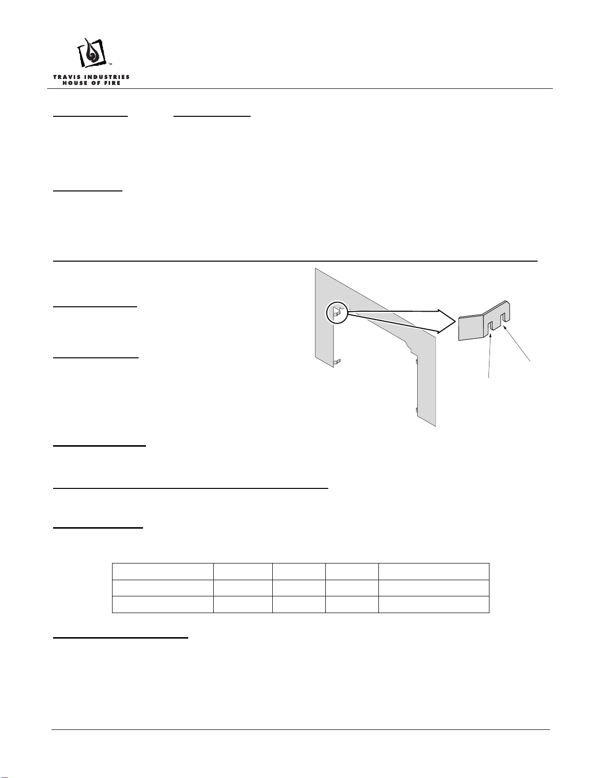
Arched Faces with Screens (2014 or later) Require Use of the Extended Position Notch
This surround panel has 2 notches. Notch position is
determined by the face being used (see below)
Standard Position – used for all faces except for the
new 2014 arched faces with screens. All other faces use
the standard position notch. If you are uncertain, use the
standard position.
Extended Position – used only for new arched faces
with screens (2014 or later). The extended position
allows room for the screen and eliminates the ½” gap to
the panel. The extended position notch positions the
insert ½” farther into the fireplace cavity.
Standard
Position
Extended
Position
Inside Fit Panels
The panels may be cut down in size and placed within the fireplace opening.
Rheostat and On/Off Switch Placement on 31 DVI
Install the rheostat and On/Off switch in the control panel under the firebox (see the Owner’s Manu al for details).
Fireplace Sizing
When using the 1-piece panel, make sure to accommodate the additional space required inside the fireplac e. See the
table below for details.
Fireplace Sizing Height Width Depth Protrusion onto Hearth
3-Piece Panels 19-1/2” 26-1/2” 15-1/8” 1-1/4”
1-Piece Panel 20-5/8” 29” 16-3/8” 0”
Routing the Power Cord
Because this panel fits flush against the fireplace facing, the panel does not have a notch allowing the power cord to
exit the fireplace. We recommend using the insert wiring kit (sku 97200315) to route power to the insert. Otherwi se,
route the power cord behind the panel to the right side (the panel or fireplace may be notched, if required).
Page 1 of 2 2/25/2014 17601666 © Travis Industries, Inc.
Page 2
1-Piece Surround Panel (DVS/31 DVI)
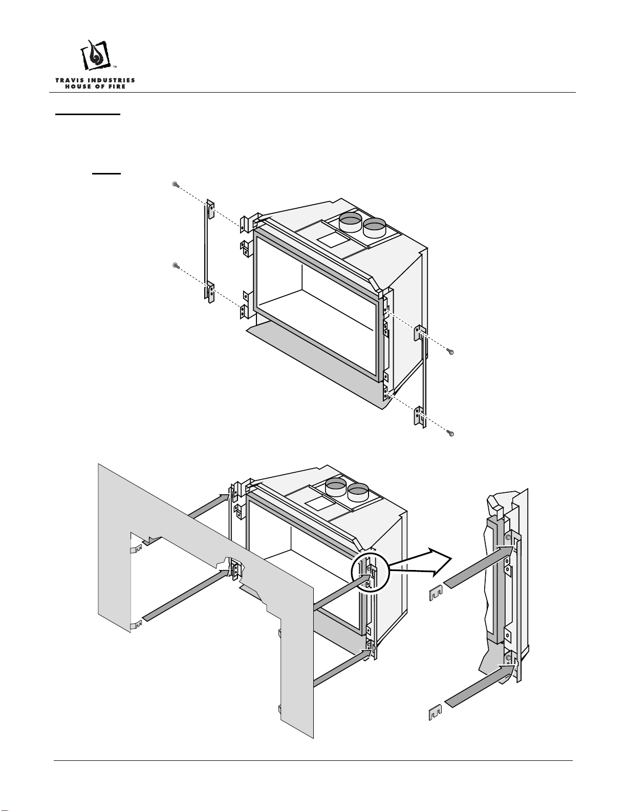
Installation
Before installation the insert should be in place with the gas line and vent attached. Pull the insert out slightly to
assist in the installation.
1. Attach the mounting brackets as shown below.
NOTE: The brackets attach to the face mounting brackets when using “No-Panel” or “Double-Door” faces.
2. Attach the surround panel as shown below.
Page 2 of 2 2/25/2014 17601666 © Travis Industries, Inc.
 Loading...