

Page 1

Page 2
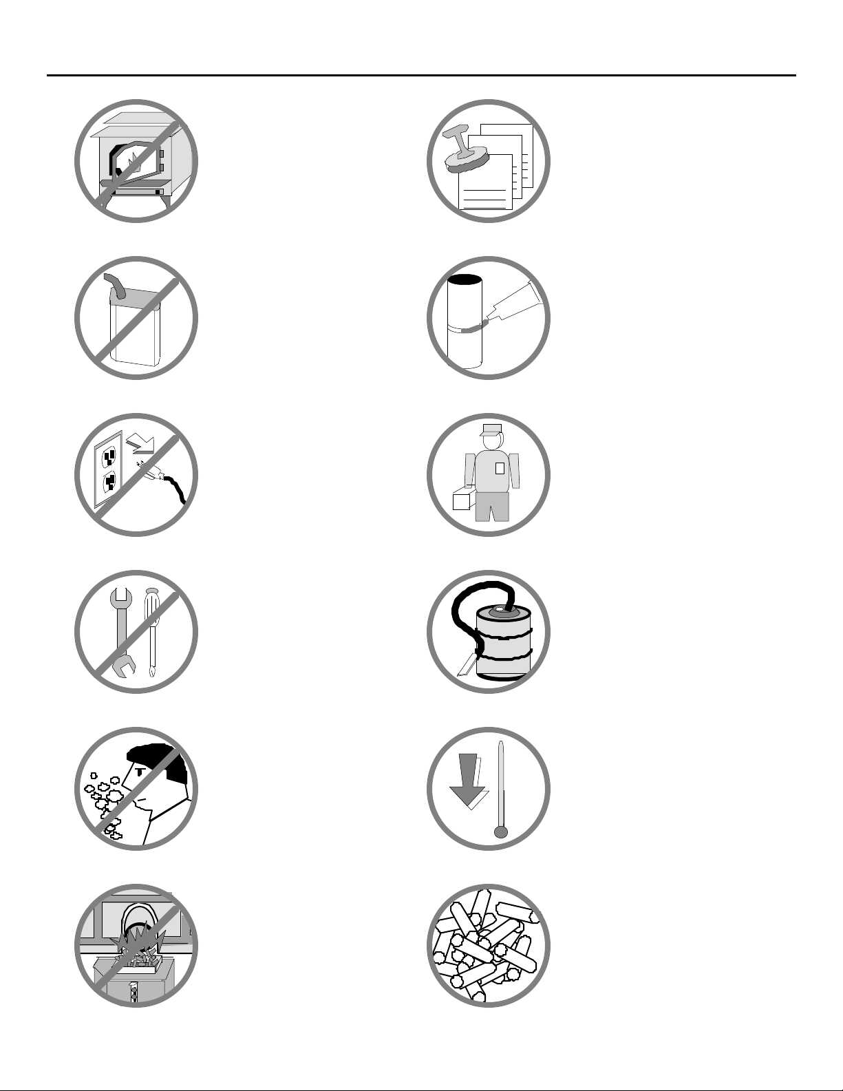
PAGE 2 SAFETY PRECAUTIONS
Gas
• The viewing door and
ashpan must be closed
and latched during
operation.
• Never block free airflow
through the open vents of
the unit.
• Gasoline or other
flammable liquids must
never be used to start the
fire or "Freshen Up" the
fire. Do not store or use
gasoline or other
flammable liquids in the
vicinity of this heater.
• Do not unplug the heater
if you suspect a
malfunction. Turn the
POWER switch to "OFF"
and periodically inspect
the heater.
Vent
Ok
Sealant
• Contact your local
building officials to
obtain a permit and
information on any
installation restrictions or
inspection requirements in
your area. Notify your
insurance company of this
heater as well.
• The exhaust system must
be completely airtight and
properly installed. The
pellet vent joints must be
sealed with RTV 500o F.
(260o C.) silicone sealant.
• This unit must be properly
installed to prevent the
possibility of a house fire.
The instructions must be
strictly adhered to. Do
not use makeshift
methods or compromise
in the installation.
• Never try to repair or
replace any part of the
heater unless instructions
are given in this manual.
All other work should be
done by a trained
technician.
• Do not operate the heater
if you smell smoke
coming from the heater.
Turn the POWER switch to
"OFF", monitor your
heater, and call your
dealer.
• Do not set the controls so
the firepot overfills with
pellets during operation.
Turn the BURN RATE to
"OFF" and periodically
inspect the heater (see
"Running Your Heater").
• Your heater requires
periodic maintenance and
cleaning (see
"Maintaining Your
Heater"). Failure to
maintain your heater may
lead to smoke spillage in
your home.
• Allow the heater to cool
before carrying out any
maintenance or cleaning.
Ashes must be disposed in
a metal container with a
tight lid and placed on a
non-combustible surface
well away from the home
or structure.
• This heater is designed
and approved for
pelletized wood fuel only.
Any other type of fuel
burned in this heater will
void the warranty and
safety listing.
Page 3

SAFETY PRECAUTIONS (CONTINUED) PAGE 3
• The heater will not
operate during a power
outage. If a power outage
does occur, check the
heater for smoke spillage
and open a window if any
smoke spills into the
room.
• Keep foreign objects out
?
of the hopper.
Mobile
Home
• Remove the power cord
and make sure the heater
has completely cooled
before performing any
maintenance. NOTE:
Turning the POWER
switch to "OFF" does not
disconnect all power to
the heater.
• This heater must be
connected to a standard
115 V., 60 Hz grounded
electrical outlet. Do not
use an adapter plug or
sever the grounding plug.
Do not route the electrical
cord underneath, in front
of, or over the heater.
• When installed in a
mobile home, the heater
must be bolted to the
floor, have outside air,
and not be installed in the
bedroom (Per H.U.D.
requirements). Check
with local building
officials.
• The exhaust system
should be checked twice a
year minimum for any
build-up of soot or
creosote.
This
Manual
• Use the AIR CONTROL
knob to keep the flame
from becoming sooty
(smoky). See the section
"Running Your Heater "
for instructions on
properly using the AIR
CONTROL.
• Do not throw this manual
away. This manual has
important operating and
maintenance instructions
that you will need at a
later time. Always follow
the instructions in this
manual.
• Use the AIR CONTROL
knob to keep the flame
brisk and yellow. See the
section "Running Your
Heater" for instructions
on properly using the AIR
CONTROL.
• Travis Industries, Inc.
grants no warranty,
implied or stated, for the
installation or
maintenance of your
heater, and assumes no
responsibility of any
consequential
damage(s).
Page 4

PAGE 4 TABLE OF CONTENTS
General Information
Introduction & Important Information.......................... 1
Safety Precautions..................................................... 2
Features & Specifications ........................................... 5
Stove Installation
Planning The Installation............................................ 6
Stove Placement Requirements ................................ 7
Floor Protection Requirements ................................... 8
Alcove Installation Requirements ............................... 8
Pellet Vent Requirements ........................................... 8
Outside Air Requirements........................................... 10
Pellet Stove Installation.............................................. 11
Preparation for Installation .................................... 11
Horizontal Corner Installation................................ 12
Horizontal Installation............................................ 13
Interior Vertical Installation.................................... 14
Exterior Vertical Installation................................... 15
Installation into Existing Factory Built (Class "A")
Chimney ................................................................ 16
Hearth Stove Installation (Uses existing masonry or
Z.C. fireplace)........................................................ 17
Insert Installation
Planning The Installation............................................ 18
Insert Placement Requirements ................................. 18
Insert Size Requirements ........................................... 19
For ZC and Masonry Fireplaces........................... 19
For Built-In Installations......................................... 19
Hearth Requirements................................................. 19
Pellet Vent Requirements ........................................... 19
Outside Air Requirements........................................... 20
Insert Installation......................................................... 20
Preparation for Installation .................................... 20
Installing the Panels,Trim, and Switch Box ........... 20
Exhaust Tube Specifications ................................ 21
Installation into a Masonry Fireplace..................... 23
Installation into an existing Zero Clearance (Metal)
Fireplace............................................................... 24
Installation as a Built-In Heater ............................ 25
Operating Your Heater
Priming the Auger ...................................................... 28
A Word about Pellets ................................................. 28
Location of Controls ................................................... 29
Starting Your Heater .................................................. 30
Running Your Heater ................................................. 31
Turning off the Heater ................................................ 32
Normal Operating Sounds ......................................... 32
Maintaining Your Heater
Maintenance Schedule............................................... 33
Check the Firepot ................................................. 33
Check the Ashpan ................................................ 34
Clean the Heat Exchanger Tubes ........................ 34
Clean the Firebox and Glass................................ 34
Clean the Ash Traps............................................. 35
Clean the Hopper and Auger Tube....................... 35
Clean the Exhaust Ducts...................................... 36
Accessing Internal Components ................................ 36
Convection Blower ............................................... 37
Exhaust Blower..................................................... 38
Pellet Vent ............................................................ 39
Troubleshooting
Troubleshooting Table.......................................... 40
Air Leaks............................................................... 41
Jammed Auger ..................................................... 41
Fuse Blown........................................................... 42
Poor Quality Pellets.............................................. 42
Safety Features .................................................... 42
How this Pellet Heater Works............................... 43
Replacement Parts ............................................... 44
Warranty ............................................................... 45
Product Listing Information................................... 46
Optional Equipment
Ceramic Log Set................................................... 47
Stove Legs ........................................................... 48
Stove Pedestal ..................................................... 48
Center flue adapter............................................... 49
Insert Front Support ............................................. 50
A WORD ABOUT THIS MANUAL
This manual uses symbols on the left side of the page to highlight information outside of the
direct subject matter. This information can be very helpful when learning about your new heater.
The three symbols used in this manual are listed below.
HINT: Information that makes a procedure or task easier, but is not
WARNING: This is a smoke warning Ð failure to heed this warning may lead to
NOTE: This is a pellet note. Because pellets vary from bag to bag, and
necessary.
smoke entering your home.
because they have a large impact on your heater's operation, this
additional information was included in this manual.
Page 5
FEATURES AND SPECIFICATIONS PAGE 5
Installation Options:
¥ Freestanding
¥ Freestanding in an Alcove
¥ Freestanding in a Mobile Home
¥ Masonry Fireplace Insert
¥ Factory-Built (Z.C.) Fireplace Insert
¥ Built-In Insert (requires a floor shield)
Heating Specifications:
Approximate Maximum Heating Capacity (in square feet)* 800 to 2000 800 to 2000
Burn Rate (Pounds per Hour)** 1.2 to 4.7 1.2 to 4.7
Maximum Burn Time on Low Burn** 30 Hours 40 Hours
Hopper Capacity 40 Pounds 50 Pounds
* Heating capacity will vary depending on the home's floor plan, degree of insulation, and the outside temperature. It is also
affected by the fuel size, quality, and moisture level.
** Small pellets will increase or decrease the stated burn rates and burn times. Differences of plus or minus 20% depending on
fuel quality may occur.
Features:
¥ Convenient Operating Controls
¥ Wide Range of Heat Output
¥ Huge Hopper for Long Burning
¥ Quiet Operation
¥ Easy to Clean and Maintain
¥ Durable Stainless Steel Firepot
¥ Tough Auger System
¥ Optional Self-Ignition System
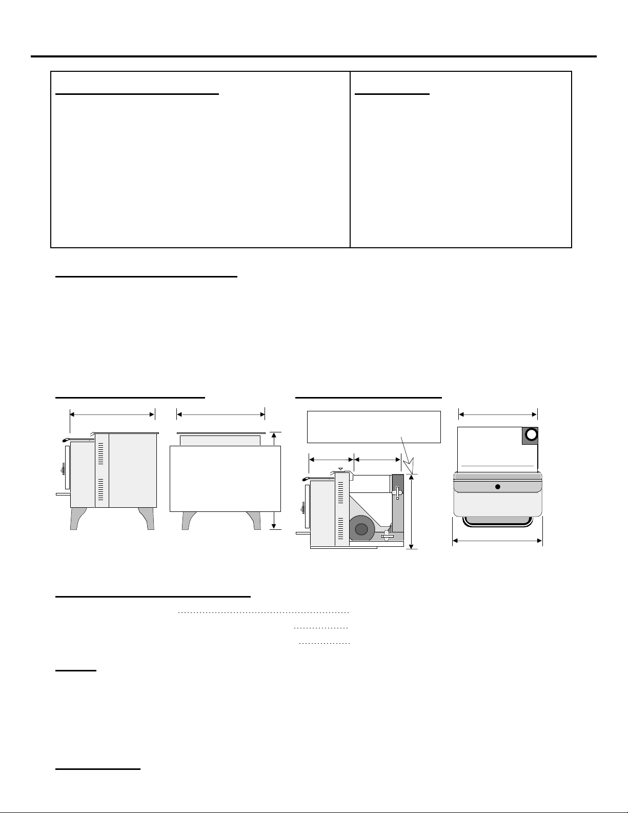
900 PS 900 PI
900 PS Dimensions 900 PI Dimensions
24 5/16"21 1/2"
Allow an extra inch in height
for installation (see page 19)
HEIGHT:
With Pedestal 31 1/8"
With Brass Legs 27 3/4"
With Cast Legs 27 3/4"
With Black Legs 26 3/8"
12 7/8"
12 1/4"
19"
Flue Opening Diameter = 3" (Both)
Weight = 240 Pounds Weight = 230 Pounds
Electrical Specifications:
Electrical Rating: 115 Volts, 3.6 Amps, 60 Hz
Watts While Using Self-Ignition System: 400
Watts During Operation (Approximately): 180
Fuel:
The unit is designed to operate using 1/4 inch diameter wood pellets that comply with the
standards set by the Association of Pellet Fuel Industry (density of at least 40 lbs. per cubic foot,
1/4" to 5/16" diameter, length no greater than 1 1/2", 8200 BTU's/lb., moisture under 8% by
weight, ash under 1% by weight, and salt under 300 parts per million). If the fuel does not
comply to this standard, the unit may not operate as designed. If the pellets are larger that 1/4
inch diameter the heater may need adjustments; consult with your dealer.
21"
24 1/4"
Emissions: 0.8 Grams Per Hour (EPA Exempt) Ð Tests conducted by E.E.M.C. Laboratory
Page 6

PAGE 6 STOVE INSTALLATION
BEFORE YOU BEGIN
READ THIS ENTIRE MANUAL BEFORE YOU INSTALL AND USE YOUR
NEW HEATER. FAILURE TO FOLLOW THE INSTRUCTIONS MAY RESULT
IN PROPERTY DAMAGE, BODILY INJURY, OR EVEN DEATH.
Check with local building officials for any permits required for installation of this pellet heater
and notify your insurance company before proceeding with installation.
PLANNING THE INSTALLATION
HINT: We suggest that you have an authorized Travis Industries dealer
install your heater. If you install the heater yourself, your authorized
dealer should review your plans for installation.
Before installing the stove, make a detailed sketch of the installation with all the dimensions
listed. Double-check all of the dimensions with the requirement sections of this manual to assure
yourself of a proper installation. The list below outlines the requirements that will most likely
affect your planning decisions.
Stove Placement ¥ Stove must be placed so that no combustibles are within, or can swing within (e.g.
drapes, doors), 36" of the front of the heater
¥ If the stove is placed in a location where the ceiling height is less than 7', it must
follow the requirements in the section "Alcove Installation Requirements"
¥ Rear and side clearances are determined by heater orientation (straight vs. corner)
and the pellet vent route (see "Stove Placement Requirements")
Pellet Vent Route ¥ Pellet vent must maintain a minimum 3" clearance to any combustible
¥ No more than 180o of elbows (two 90o elbows, or two 45o & one 90o elbow, etc.)
NOTE: The center flue adapter is considered a 90o elbow
¥ Maximum 33' length if vertical only
¥ Maximum 10' horizontal length if vertical rise is 25' or less'
¥ Maximum 4' horizontal length if vertical rise is 30' to 25'
Pellet Vent
Diameter
Pellet Vent Type ¥ Must be Type "L" pellet vent (except hearth stove installations Ð see that section) -
Floor Protection ¥ Minimum size of 24 5/16" wide by 27 1/2" deep (6" in front, 0" on sides and back)
Mobile Home
Requirements
Outside Air ¥ Required for mobile homes
¥ If the pellet vent is over 15' in total vertical length use 4" diameter
¥ If the pellet vent is over 4' in total horizontal length use 4" diameter
¥ If the heater is installed at an altitude over 4000' use 4" diameter
¥ Otherwise, use 3" or 4" diameter
or - connect the vent to a factory built type "A" chimney (adapter required)
¥ Must be non-combustible and at least .018" thick (26 gauge)
¥ Outside air is required
¥ The heater must be bolted to the floor (Some states do not require this; check with
your local building department)
¥ The heater must be grounded to the steel chassis of the mobile home (Some states
do not require this; check with your local building department)
¥ Must not be drawn from an enclosed space (garage, unventilated crawl space)
¥ Travis Industries strongly suggests outside air for all residential installations,
especially for those that are energy efficient, air tight homes.
WARNING: During a power outage there is a possibility of some smoke entering
the room if an outside air connection is not used.
Page 7
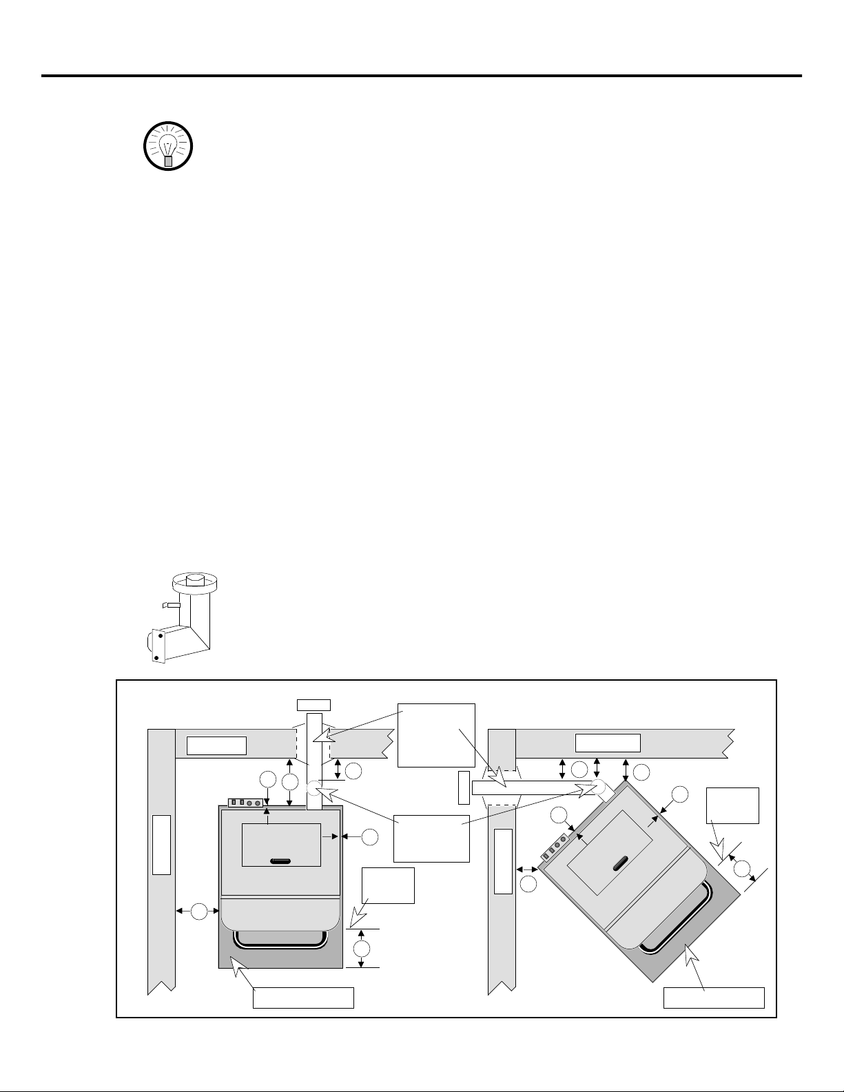
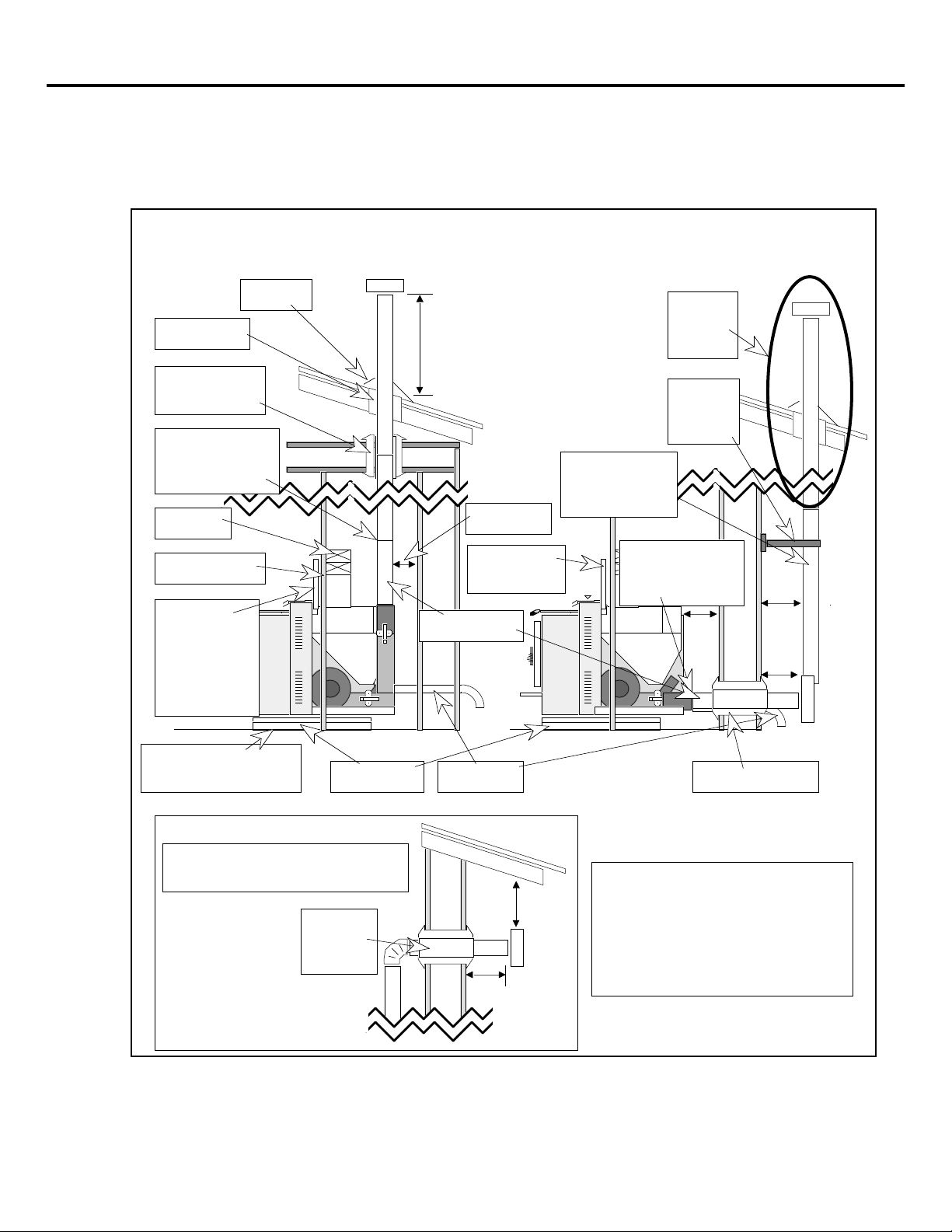
STOVE PLACEMENT REQUIREMENTS
ellet Vent
HINT: REDUCING CLEARANCES - Clearances may be reduced by
methods specified in NFPA 211, listed wall shields, pipe shields, or
other means approved by local building or fire officials.
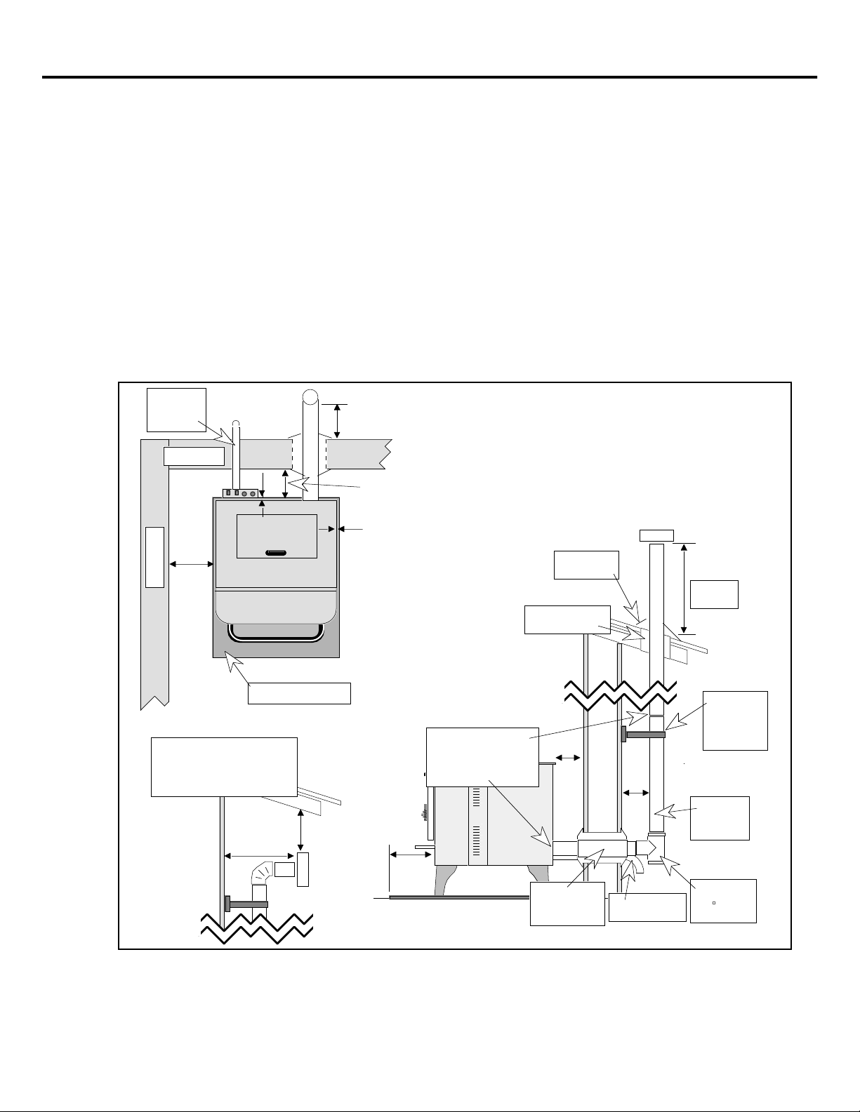
The stove must be placed so all of the requirements below are met:
¥ Heater must be placed so that no combustibles are within, or can swing within,
36" of the front of the heater (e.g. drapes, doors)
¥ Heater and floor protection must be installed on a level, secure floor
STRAIGHT INSTALLATION (see the illustration below)
A 9" clearance from the heater to the sidewall
B* 3" clearance from the heater to the backwall and the pellet vent must maintain the
clearance outlined in clearance C below
C* The pellet vent must maintain a 3" clearance to any wall except when passing
through an approved thimble.
CORNER INSTALLATION (see the illustration below)
C* The pellet vent must maintain a 3" clearance to any wall except when passing
through an approved thimble.
G* 2" from the rear corner of heater to the cornerwall
STOVE INSTALLATION (CONT.) PAGE 7
* If an interior vertical pellet vent is being used, the clearance to the backwall is determined by
the upward-turning elbow or "Tee". It will vary in depth depending on the brand of pellet
vent used. Before establishing the heater placement, connect the elbow or "Tee" and measure
off the 3" clearance to the backwall to establish the heater position.
The center flue adapter allows the stove to be located closer to the backwall
(measurement "B") when using an interior vertical pellet vent. For corner
installations, the adapter must maintain a 3" clearance to the cornerwall . For
straight installations the following dimensions can be used to determine the
heater location:
DIAMETER OF VENT: 3" 6"
BACKWALL TO STOVE MAY BE A MIN. OF: 7" 9"
STRAIGHT
INS T A L L A T I O N
Backwall
Sidewall
A
Direct or
Exterior
Vertical
Pellet Vent
F
B
C
E
Door
Opening
Interior
Vertical
P
CORNER
INS T A L L A T I O N
Cornerwall
C
F
G
Cornerwall
G
E
Door
Opening
D
Floor protection
D
Floor protection
Page 8
PAGE 8 STOVE INSTALLATION (CONT.)
FLOOR PROTECTION REQUIREMENTS (See the illustration on the previous page)
The heater must be installed with floor protection that meets the following requirements:
¥ Made of a non-combustible material at least .018" thick (26 gauge)
¥ Extend under and 2" to each side of a chimney "Tee" if one is used
D Must extend 6" in front of the heater (measured from door opening)
E Must cover the area underneath the heater and 0" to each side ( Min. 24 5/16" wide)
F Must cover the area underneath the heater and 0" to the rear (Min. 27 1/2" deep)
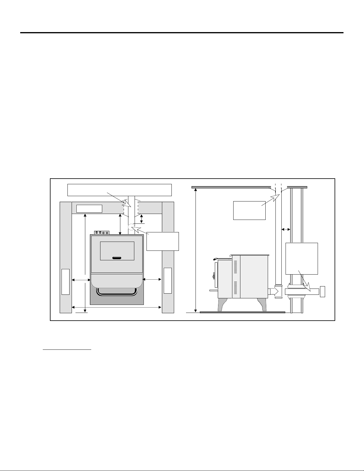
ALCOVE INSTALLATION REQUIREMENTS
Whenever the pellet stove is placed in a location where the ceiling height is less than 7' tall, it is
considered an alcove installation. Because of the reduced height, the special installation
requirements listed below must be met.
¥ Minimum height is 60" ¥ Minimum width is 42 5/16"
¥ Maximum depth is 48" ¥ Minimum clearance of 9" on each side and 3" on back
Horizontal or Vertical Exterior Pellet Vent
Backwall
3" Min.
48"
Max.
9"
Min.
Sidewall
42 5/16" Min.
PELLET VENT REQUIREMENTS
Pellet Vent Type
¥ Must be Type "L"(except for masonry fireplace installations) - or - connect the
vent to a factory built type "A" chimney (adapter required)
¥ If the pellet vent is over 15' in total vertical length use 4" diameter (use adapter)
¥ If the pellet vent is over 4' in total horizontal length use 4" diameter (use adapter)
¥ If the heater is installed at an altitude over 4000' use 4" diameter (use adapter)
¥ Otherwise, use 3" or 4" diameter
¥ Follow the manufacturer's installation instructions for precautions required for
passing vent through a combustible wall or ceiling (i.e. use an approved thimble).
¥ Must have a support bracket every 5' of pellet vent when exterior
3" Min.
Vertical
Pellet Vent
9"
Min.
Vertical
Pellet Vent
3"
Min.
60" Min.
Horizontal
or Vertical
Exterior
Pellet Vent
Sidewall
Page 9

Pellet Vent Installation Options
¥ Minimum 3" clearance to any combustible
¥ No more than 180o of elbows (two 90o elbows, or two 45o & one 90o elbow, etc.)
NOTE: The Center Flue Adapter is the same as a 90o elbow.
¥ Maximum 33' rise if vertical only
¥ Maximum 10' length if horizontal only
¥ Maximum 10' horizontal length if vertical rise is 25' or less
¥ Maximum 4' horizontal length if vertical rise is 30' to 25'
¥ Do not connect the pellet vent to a vent serving any other appliance or stove
STOVE INSTALLATION (CONT.) PAGE 9
See maximum
horizontal length
Support
bracket
every 5'
Installing the Pellet Vent
¥ Pellet vent connections must be screwed together with sheet metal screws and
sealed airtight with 500o F. RTV silicone
Approved
thimble
See "Pellet Vent
Termination"
Joints must be
sealed and
screwed together
Type "L" Vent
3" Minimum
See maximum
vertical rise
Maximum
180 of
elbows
Floor
protection
under "Tee"
¥ The pellet vent connects to the exhaust
vent 5 3/4" from the center of the stove and
the distance listed below for the type of
legs or pedestal used (see the illustration to
the right):
Pedestal 13 1/8"
Brass Legs 9 3/4"
Cast Legs 9 3/4"
Black Legs 8 3/8"
Exhaust Vent
(3" Inside
Diameter)
Center Line
5 3/4"
See the Table
Page 10

PAGE 10 STOVE INSTALLATION (CONT.)
Pellet Vent Termination (See the illustration below)
¥ Must have an approved cap (to prevent water from entering) or a 45o downturn
¥ If the termination is located on a windy side of the house, an approved house
shield is recommended to prevent soot from building up on the side of the house
¥ Must not be located where it will become plugged by snow or other material
A Minimum 4' clearance below or beside any door or window that opens
B Minimum 1' clearance above any door or window that opens
C Minimum 2' clearance from any adjacent building
D Minimum 7' clearance above any grade when adjacent to public walkways
E Minimum 2' clearance above any grass, plants, or other combustible materials
F Minimum 3' clearance from any forced air intake of any other appliance
G Minimum 2' clearance below eaves or overhangs
H Minimum 1' clearance horizontally from combustible wall
X Must be a minimum of 2' above the roof
C
OUTSIDE AIR REQUIREMENTS
¥ Required for mobile homes
¥ Must not be drawn from an enclosed space (garage, unventilated crawl space)
¥ Must not be over 15' long
¥ Must be made with 1 3/4" diameter or larger
metal or aluminum duct with a metal screen
attached to the end to keep out rodents
(P.V.C. or other combustible materials may
not be used)
¥ The outside air connects to the outside air
inlet 3 3/16" from the center of the stove and
the distance listed below for the type of legs
used (see the illustration to the right):
Pedestal 13 1/4"
Brass Legs 9 7/8"
Cast Legs 9 7/8"
Black Legs 8 1/2"
X
B
A
G
E
A
H
F
Outside Air Inlet
(1 3/4" Outside Dia.)
D
Center Line
3 3/16"
See the Table
Page 11
Outside Air Requirements (Continued)
¥ Must not terminate above or within 1' of the chimney termination
¥ Must have a rain cap or down-turned elbow to prevent water from entering
¥ Must be located so that it will not become plugged by snow or other material
¥ Travis Industries strongly suggests outside air for all residential installations,
especially for those that are energy efficient, airtight homes
WARNING: During a power outage there is a possibility of some smoke entering
PELLET STOVE INSTALLATION
The following pages detail the six different installations available for the Avalon 900 PS pellet
stove. The drawings used for each type of installation detail most, but not all, of the
requirements necessary for a safe installation. The section "Stove Requirements" details the rest
of the installation requirements. The six types of installations available are listed below along
with considerations important to the installation:
Installation Type Installation Considerations
STOVE INSTALLATION (CONT.) PAGE 11
the room if an outside air connection is not used.
Horizontal Corner 3" Clearance to Pellet Vent
Horizontal 3" Clearance to Pellet Vent
Interior Vertical "Tee" or Elbow Determines Rear Clearance
Exterior Vertical Penetrates Wall Directly Behind Stove
Vertical Using Existing Factory Built Chimney Uses Existing Type "A" Chimney
Hearth Stove Uses Existing Masonry or Z.C. Chimney
Prior to installing your stove make a detailed plan with dimensions to double-check them against
the requirements. When ready to install, first follow the instructions in the section "Preparation
for Installation" below. Then follow the order of installation detailed in the type of installation
being used.
Preparation for Installation
¥ Check for damage to the exterior of the stove (dents should be reported, scratches
can be fixed by applying touch up paint).
¥ Check the interior of the firebox. Make sure the firebrick refractory is not cracked
and that the firepot holder and ash trap doors are in place.
¥ Any optional equipment being used for this pellet stove should be installed (see
the section "Optional Equipment"). The stove must use legs or a pedestal. If
using a center flue adapter, we suggest installing it at this point (these components
affect the location where the pellet vent connects to the heater).
HINT: We suggest starting the heater outside and burning it for two hours to
cure the paint before it is placed in the home.
Page 12

PAGE 12 STOVE INSTALLATION (CONT.)
otectio
otectio
Horizontal Corner Installation
The horizontal corner installation is often used because it takes up very little space. Make sure to
follow all of the requirements listed in the section "Stove Requirements" as well as those listed
below in the illustration. The steps below detail the order of installation.
HINT: Make sure to carefully plan the pellet vent route so that it always
maintains a 3" clearance to combustibles.
A Install the floor protection.
B Install the pellet vent. Make sure to follow the pellet vent manufacturer's instructions for
passing the vent through combustible walls. Screw together all pellet vent joints and seal.
Install the outside air connection (if applicable).
WARNING: Because this type of installation does not have any vertical rise to
create draft, we recommend using outside air with this type of
installation.
C Place the pellet stove in position and attach the pellet vent and outside air connection (if
applicable). Screw together and seal the pellet vent connection to the stove.
D Read the section "Operating the Heater" prior to plugging in the stove and operating.
Approved thimble
1'
Min.
Outside
Air
3" Min.
0"
2"
Min.
Cornerwall
Optional Direction
Cornerwall
2" Min.
0"
Floor
Pr
Door
Opening
6"
n
Outside Air Termination
with 90 elbow or hood
Joints must be
screwed together
and sealed
Type
"L" Vent
Cornerwall
1'
Min.
Floor
Pr
n
Page 13

STOVE INSTALLATION (CONT.) PAGE 13
Horizontal Installation
The horizontal installation minimizes the amount of pellet vent needed by passing the pellet vent
through the wall with a thimble. Make sure to follow all of the requirements listed in the section
"Stove Requirements" as well as those listed below in the illustration. The steps below detail the
order of installation.
HINT: Make sure to carefully plan the pellet vent route so that it always
maintains a 3" clearance to combustibles.
A Install the floor protection.
B Install the pellet vent. Make sure to follow the pellet vent manufacturer's instructions for
passing the vent through combustible walls. Screw together all pellet vent joints and seal.
Install the outside air connection (if applicable).
WARNING: Because this type of installation does not have any vertical rise to
create draft, we recommend using outside air with this type of
installation.
C Place the pellet stove in position and attach the pellet vent and outside air connection (if
applicable). Screw together and seal the pellet vent connection to the stove.
D Read the section "Operating the Heater" prior to plugging in the stove and operating.
Outside
Air
Backwall
Sidewall
9"
Min.
0"
Floor protection
Floor protection
1'
Min.
Min.
Door
Opening
3"
0"
6"
Min.
Outside Air Termination
with 90 elbow or hood
Joints must be
screwed together
and sealed
Approved
thimble
3"
Min.
pointed down or
pellet vent cap
Outside Air
45 elbow
Type
"L" Vent
Page 14

PAGE 14 STOVE INSTALLATION (CONT.)
Interior Vertical Installation
The interior vertical installation requires an elbow, "Tee", or center flue adapter. It is important
to take into consideration the depth of the elbow, "Tee", or center flue adapter when determining
the placement of the stove. Elbows and "Tee's" vary in depth among manufacturers and affect
the minimum 3" pellet vent clearance to the backwall. For improved rear clearance, use the
Travis Industries center flue adapter (available at your dealer). Make sure to follow all of the
requirements listed in the section "Stove Requirements" as well as those listed below in the
illustration. The steps below detail the order of installation.
HINT: Install the elbow, "Tee", or center flue adapter before you start the
installation so that an accurate measurement can be made for the
distance between the stove and the backwall.
A Install the floor protection.
B Install the pellet vent (it must maintain a 3" clearance). The pellet vent may pass through
the ceiling and roof before termination or turn sideways and terminate along an outside
wall (see the illustration below). Make sure to follow the pellet vent manufacturer's
instructions for passing the vent through combustible walls, ceilings, or roofs. Screw
together all pellet vent joints and seal. Install the outside air connection (if applicable).
C Place the pellet stove in position and attach the pellet vent and outside air connection (if
applicable). Screw together and seal the pellet vent connection to the stove.
D Read the section "Operating the Heater" prior to plugging in the stove and operating.
Outside
Air
Backwall
Sidewall
9"
Min.
Approved
Thimble
If the termination
is below the eave,
it must maintain a
2' clearance
Wall
0"
2'
Min.
1'
Min.
3"
Min.
0"
Floor
protection
3" Clearance
Approved
Support
Joints must
be screwed
together and
sealed
Type "L" Vent
Floor protection
6"
Min.
Flashing
Min.2'
Ceiling
3" Minimum
Outside Air
under "Tee"
Page 15
STOVE INSTALLATION (CONT.) PAGE 15
Exterior Vertical Installation
This type of installation utilizes natural draft while concealing the vent outside. Make sure to
follow all of the requirements listed in the section "Stove Requirements" as well as those listed
below in the illustration. The steps below detail the order of installation.
A Install the floor protection.
B Install the pellet vent. The pellet vent may pass through the roof before termination or
turn sideways and terminate along an outside wall (see the illustration below). Make sure
to follow the pellet vent manufacturer's instructions for passing the vent through
combustible walls or roofs. Screw together all pellet vent joints and seal. Install the
outside air connection (if applicable).
C Place the pellet stove in position and attach the pellet vent and outside air connection (if
applicable). Screw together and seal the pellet vent connection to the stove.
D Read the section "Operating the Heater" prior to plugging in the stove and operating.
Outside
Air
Backwall
0"
9"
Min.
Sidewall
Floor protection
If the termination is
below the eave, it must
maintain a 2' clearance
3"
Min.
3"
Min.
0"
Joints must be
screwed together
and sealed
Flashing
3" Clearance
3"
Min.
Min.2'
Support
bracket
every 5'
3"
Min.
1'
Min.
2'
Min.
6"
Min.
Approved
thimble
Outside Air
Type
"L" Vent
Tee or
90 elbow
Page 16

PAGE 16 STOVE INSTALLATION (CONT.)
Vertical Installation into Existing Factory Built (Class "A") Chimney
This type of installation utilizes an existing class "A" chimney to vent the flue gases. An adapter
must be used to connect the pellet vent to the chimney. All of the pellet vent sections, the
adapter, and the chimney must all be sealed to prevent flue gases from entering the room. Make
sure to follow all of the requirements listed in the section "Stove Requirements" as well as those
listed below in the illustration. The steps below detail the order of installation.
A Inspect the existing class "A" chimney for any damage or deterioration. Use RTV 500o F.
silicone to seal all of the chimney joints.
B Install the floor protection.
C Install the chimney to pellet vent adapter to the chimney. Install the pellet vent. Screw
together all pellet vent joints and seal. Install the outside air connection (if applicable).
D Place the pellet stove in position and attach the pellet vent and outside air connection (if
applicable). Screw together and seal the pellet vent connection to the stove.
E Read the section "Operating the Heater" prior to plugging in the stove and operating.
Outside
Air
Backwall
Sidewall
9"
Min.
The pellet
vent can be
connected to
an exterior
Class "A"
chimney with
an adapter
0"
3"
Min.
0"
Floor
protection
Flashing
Class "A"
Chimney
Approved
Class "A"
Floor Thimble
Joints must be
screwed together
and sealed
Type "L" Vent
Min. 3' tall
and 2'
above any
part of the
roof within
10'
Pellet Vent
to Class "A"
Chimney
Adapter
Required
3" Minimum
Outside Air
6"
Min.
Floor protection
under "Tee"
Page 17

STOVE INSTALLATION (CONT.) PAGE 17
Hearth Stove Installation (Uses existing masonry or Z.C. fireplace)
When installing the stove into an existing masonry or Z.C. fireplace (called a "Hearth Stove"
installation), there are two options for routing the pellet vent. Both options allow the use of
either type "L" pellet vent, stainless steel single wall liner, or flexible stainless steel liner.
NOTE: Z.C. (Metal) fireplaces require a positive connection installation.
¥ The first option is a direct connection. It relies upon a non-combustible block-off plate at the
damper location to form an air tight seal between the flue gases and the masonry chimney. It
must be sealed with Kaowool or high-temperature insulation. The pellet vent must extend a
minimum of 1' above the block-off plate or to the first flue tile if the chimney has a tile lining.
¥ The second option is a positive connection (also called a complete reline). An air tight cover
plate is required at the top of the masonry chimney (use 500o F. RTV silicone to seal). A
positive connection is recommended because it is easier to clean.
Make sure to follow all of the requirements listed in the section "Stove Requirements" as well as
those listed below in the illustration. The steps below detail the order of installation.
A Inspect the existing fireplace for any damage or deterioration. Repair any damage before
proceeding. If installing in a Z.C. fireplace, remove the damper to allow the pellet vent to
pass through the chimney.
B Install the floor protection.
C Install the pellet vent. Screw together all pellet vent joints and seal. Install the outside air
connection (if applicable).
NOTE: No modification to the Z.C. firebox is allowed.
D Place the pellet stove in position and attach the pellet vent and outside air connection (if
applicable). Screw together and seal the pellet vent connection to the stove.
E Read the section "Operating the Heater" prior to plugging in the stove and operating.
DIRECT CONNECTION POSITIVE CONNECTION (full reline)
A non-combustible block-off plate
must be installed to form an airtight
seal between the pellet vent and
masonry chimney (use Kaowool or
high-temperature insulation to seal)
Hearth and/or
hearth pad
6"
Min.
Min.
Outside air
Cover plate must
be sealed air
tight with silicone
Type "L", stainless steel
single wall, or stainless
steel flexible vent
Optional outside air route
Joints must be
1'
screwed together
and sealed
Hearth and/or
hearth pad
6"
Min.
1'
Min.
Preferred
outside air route
6"
Min.
Page 18
PAGE 18 INSERT INSTALLATION
BEFORE YOU BEGIN
READ THIS ENTIRE MANUAL BEFORE YOU INSTALL AND USE YOUR
NEW HEATER. FAILURE TO FOLLOW THE INSTRUCTIONS MAY RESULT
IN PROPERTY DAMAGE, BODILY INJURY, OR EVEN DEATH.
Check with local building officials for any permits required for installation of this pellet heater
and notify your insurance company before proceeding with installation.
PLANNING THE INSTALLATION
HINT: We suggest that you have an authorized Travis Industries dealer
The Avalon 900 PI insert was designed to be installed into an existing masonry or zero-clearance
(metal) fireplace, or built directly into the wall (see the section "Built-In Installation"). The
requirements listed below are required for every type of installation and must be followed. In
addition, each type of installation has unique requirements that must be met besides the
requirements listed below. Hence, it is very important to follow the requirements listed in the
section "Insert Requirements" and the installation instructions specific to the type of
installation being used. Make a sketch of your installation including dimensions before
installing to double-check against the requirements listed.
install your heater. If you install the heater yourself, your authorized
dealer should review your plans for installation.
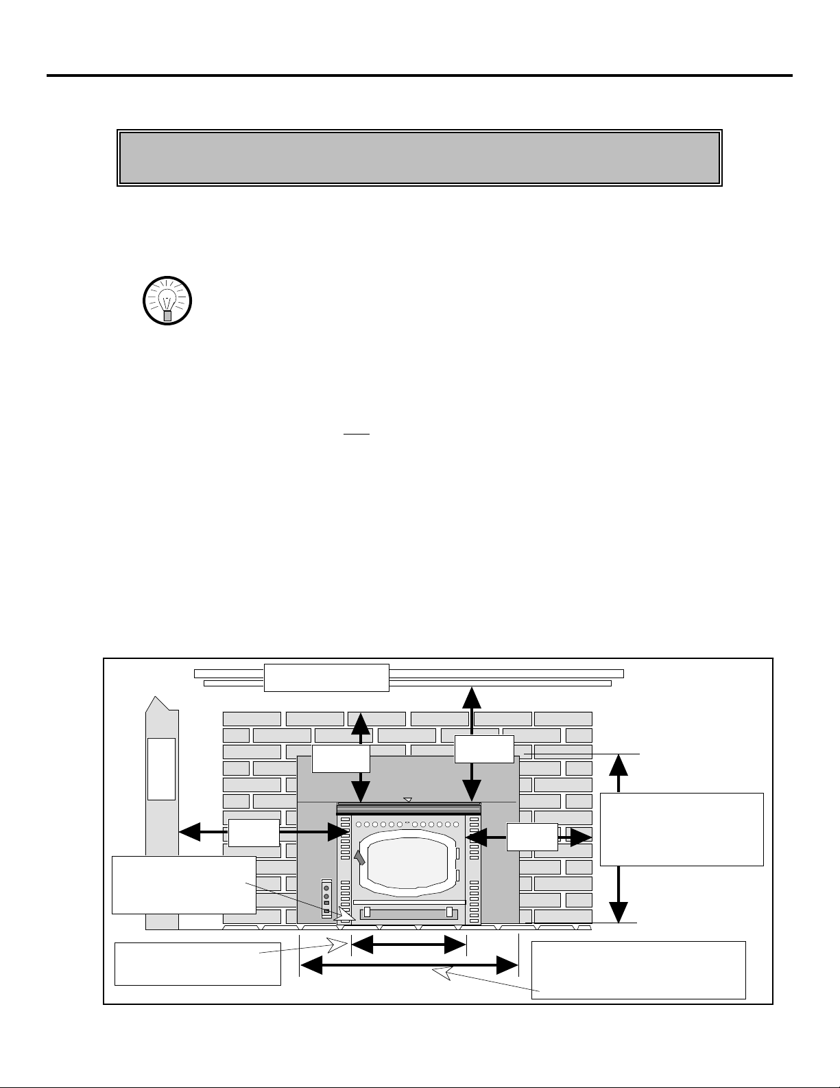
INSERT PLACEMENT REQUIREMENTS (See the illustration below)
¥ The insert must be placed so that no combustibles are within, or can swing within
(e.g. drapes, doors), 36" of the front of the heater
¥ Insert and floor protection must be installed on a level, secure floor
¥ The insert must maintain a 9" clearance to sidewalls
¥ The non-combustible side facing must extend 8" from the side of the insert
¥ The non-combustible top facing must extend 12" above the top of the insert
¥ The combustible mantle must be at least 13" above the top of the insert
Combustible Mantle
12" Min.
Sidewall
9" Min.
Floor protection must
extend underneath
insert to the faceplate
13" Min.
8" Min.
HEIGHT INCLUDING
TOP PANEL:
28 7/8" with 8"x10" Panels
31 7/8" with 10"x13" Panels
21 1/4" Min.
(Width of Floor Protection)
WIDTH INCLUDING SIDE PANELS:
40 3/8" with 8"x10" Panels
44 3/8" with 10"x13" Panels
Page 19

INSERT SIZE REQUIREMENTS
For ZC and Masonry Fireplaces
21" Minimum
INSERT INSTALLATION (CONT.) PAGE 19
* The minimum fireplace
size is larger in front
than in back because
the switch box slides
into the left side panel
and goes into the
fireplace cavity.
20" Minimum
12 1/4" Minimum
29 3/4" Minimum*
For Built-In Installations
See the section "Built-In Installation" for details on size requirements for this type of installation.
HEARTH REQUIREMENTS (See the illustration above)
¥ Built-in Installations require a floor shield, which meets the hearth requirement
¥ Must extend below the insert on all sides (Min. 21 1/4" wide)
¥ Must be non-combustible and at least .018" thick (26 guage)
PELLET VENT REQUIREMENTS
NOTE: Built-In installations have special pellet vent requirements that exceed the
requirements listed below (see the section "Built-In Installation").
¥ Stainless steel single wall, type "L", or stainless steel flexible vent must be used
for masonry fireplaces or zero-clearance (metal) installations, built-in installations
require type "L" pellet vent
¥ Must not connect to a vent serving any other appliance or stove
¥ All pellet vent connections must be screwed together with sheet metal screws and
sealed airtight with 500o F. RTV silicone
¥ Must have an approved cap (to prevent water from entering)
¥ No more than 180o of elbows (two 90o elbows, or two 45o & one 90o elbow, etc.)
¥ Maximum 33' length if vertical only
¥ Maximum 10' horizontal length if vertical rise is 25' or less
¥ Maximum 4' horizontal length if vertical rise is 30' to 25'
Pellet Vent Diameter
¥ If the pellet vent is over 15' in total vertical length use 4" diameter
¥ If the pellet vent is over 4' in total horizontal length use 4" diameter
¥ If the heater is installed at an altitude over 4000' use 4" diameter
¥ Otherwise, use 3" or 4" diameter
20" Minimum
12 7/8" Minimum
Page 20

PAGE 20 INSERT INSTALLATION (CONT.)
OUTSIDE AIR REQUIREMENTS
¥ Must not be drawn from an enclosed space (garage, unventilated crawl space)
¥ Must be made with 1 3/4" diameter or larger metal or aluminum duct with a metal
screen attached to the end to keep out rodents (P.V.C. or other combustible
materials may not be used)
¥ Must not terminate above or within 1' of the chimney termination
¥ Must have a rain cap or down-turned elbow to prevent water from entering
¥ Must be located so that it will not become plugged by snow or other material
¥ Travis Industries strongly suggests outside air for all residential installations,
especially for those that are energy efficient, air tight homes
WARNING: During a power outage there is a possibility of some smoke entering
the room if an outside air connection is not used.
INSERT INSTALLATION
This section details the three types of installations that may be utilized with the Avalon 900 PI
and the pre-installation procedures that will aid in installation. The drawings used for each type
of installation detail most, but not all, of the requirements necessary for a safe installation. Read
the section "Insert Requirements" for additional requirements.
Preparation for Installation
¥ Check for damage to the exterior of the stove (dents should be reported, scratches
can be fixed by applying touch up paint).
¥ Check the interior of the firebox. Make sure the firebrick refractory is not cracked
and that the firepot holder and ash trap doors are in place.
¥ All optional equipment being used for this pellet insert should be installed after
installation with the exception of the optional pellet ignition system which should
be installed before installation (see the section "Optional Equipment").
NOTE: PANELS ARE REQUIRED WHEN INSTALLING THE 900 PI PELLET
INSERT.
HINT: We suggest starting the heater outside and burning it for two hours to
cure the paint before it is placed in the home.
Installing the Panels, Trim, and Switch Box
The panels for the 900 PI are purchased seperately from the pellet insert and are available in
three sizes. The table below details the finished size of the panels once they are installed. Make
sure to purchase the panels that will cover the fireplace opening in both height and width.
Size of Panels Height Width
8" x 10" 28 7/8" 40 3/8"
10" x 13" 31 7/8" 44 3/8"
The panels should be installed after the insert is in place and connected to the pellet vent. First
route the power cord out of the fireplace so it exits through the lower outside front corner of the
fireplace opening (do not route the power cord under the unit). Place the side panel with the
square hole in it along the left side of the insert and slide it into place. Repeat for the right side.
The panels are notched and simply clip onto the sides of the unit (see the illustration on the
following page). Unwrap the switch box (shipped inside the firebox of the heater) and clip it into
the left side panel. Make sure the power switch is at the top when installed. Then attach the
electrical connector on the end of the cord from the switch box to the electrical connector on the
left side of the insert towards the rear (see the illustration on the following page).
Page 21

INSERT INSTALLATION (CONT.) PAGE 21
Installing the Panels, Trim, and Switch Box (Continued)
The switch box clips into place into the square
hole on the left side panel. Then attach the
electrical connector on the end of the cord to the
electrical connector on the left side of the insert.
The left side
panel has a
square hole
in it for the
switch box.
The top panel slides over the flanges on the
side panels and over the top of the insert.
The side
panels clip
into place on
the side of
the insert.
The top panel then slides over the flanges on the side panels and over the top of the insert.
NOTE: The panels have a 3/8" standoff to keep the panels spaced off the fireplace facing.
This space is needed to allow air to flow into the fireplace. Do not remove this
standoff or seal the space between the panel and the facing.
CROSS SECTION OF BRASS TRIM
Set-screw that
holds the larger "L"
bracket in place
Groove where the larger
"L" bracket fits into
Groove Where Top
Panel Fits Into
Groove where the smaller
"L" bracket fits into
Front Side
Insert
Left Trim Right Trim
Smaller "L"
Brackets
Larger "L"
Brackets
Top Trim
Lay the trim on
the floor in front of
the insert with the
rounded portion
facing down.
After the panels are in place, the trim can then be installed. Place the rounded edge of the trim
that will be facing outwards when installed face down (see the illustration above). Insert one
small and one large "L" bracket leg into the grooves in the 45
the other leg of each "L" bracket into the groove in each end of the top piece. With a
screwdriver, tighten the set-screw into the larger "L" brackets, insuring that the 45
o
cut end of each side piece. Slide
o
cuts are
butted together to form a neat joint. Pick up the brass trim and slide it over the panels until the
bottom of the trim is flush with the bottom edge of the side panels.
Page 22

PAGE 22 INSERT INSTALLATION (CONT.)
Exhaust Tube Specifications
The Avalon 900 PI is shipped with a vertical exhaust tube, but it can be adjusted to vent
horizontally (i.e., for built-in installations using a horizontal vent). To vent horizontally, unlatch
the upper and lower clips on the right side of the insert (remove the locking pins first), and
remove the exhaust tube and vertical exhaust extender. Discard the vertical exhaust extender.
Attach the exhaust tube with the lower clip, making sure the lower gasket is properly aligned,
and re-insert the locking pin.
Upper Clip Exhaust Tube
Lower Clip Vertical Exhaust Extender
Unlatch both clips
Discard the vertical exhaust extender
Attach the exhaust
tube to the lower clip
Locking
Pin
The illustration below details the exhaust tube location for the vertical and horizontal exhaut tube
configuration.
Exhaust Tube Location:
Center
19"
of Stove
2 5/8"
2 1/2"
8"
1 3/4"
Page 23

INSERT INSTALLATION (CONT.) PAGE 23
Installation into a Masonry Fireplace
The pellet insert can be installed into a masonry fireplace with either a direct or positive
connection (full reline). Make sure to follow all of the requirements listed in the section "Insert
Requirements" as well as those listed below. The steps below detail the order of installation.
A Clean the fireplace with a wire brush or scraper and inspect the fireplace cavity and
chimney. Repair any crack or other damage before proceeding. Paint the fireplace cavity
with a latex paint to eliminate the possibility of odors from the fireplace being circulated
into the house by the pellet insert.
B Install the pellet vent, making sure to seal all joints. The direct connection requires a
block-off plate made of non-combustibles that is sealed with kaowool or high
temperature insulation. The positive connection requires a cover plate at the top of the
chimney sealed with silicone. Take into consideration the optional exhaust vent
configurations (horizontal or vertical). Install the outside air connection (if applicable).
C Install the optional igniter if it is being used. If the fireplace is stepped down, insert two
leveling bolts (included with the owner's pack) into the threaded nuts at the bottom rear of
the baseplate. Then adjust the bolts to the same height the fireplace is stepped down to.
D Place the insert into the fireplace. The outside air connection may need to be attached
before the insert is fully in place.
NOTE: Do not pick the insert up by the hopper or any other internal component.
E Attach the pellet vent to the insert by reaching over the top or to the right of the insert.
Screw the pellet vent to the exhaust tube and seal the joint.
F Install the panels and brass trim to complete the installation. Read the section "Operating
the Heater" prior to plugging in the insert and operating.
DIRECT CONNECTION POSITIVE CONNECTION (full reline)
A non-combustible block-off
plate must be installed to form
an airtight seal around the pellet
vent and masonry chimney (use
Kaowool or high-temperature
insulation to seal)
3/8" Space
(Do not seal)
Hearth and/or hearth
pad must extend at
least to the faceplate
1'
Min.
Cover plate must
be sealed air
tight with silicone
Type "L", stainless steel
single wall, or stainless
steel flexible vent
Joints must be
screwed together
and sealed
3/8" Space (Do not seal)
Hearth and/or hearth
pad must extend at
least to the faceplate
Outside air
6"
Min.
Outside air
Use the leveling bolts to level the stove
Page 24

PAGE 24 INSERT INSTALLATION (CONT.)
Installation into a Zero Clearance (Metal) Fireplace
The pellet insert can be installed into a zero clearance (metal) fireplace with a positive
connection (full reline). Make sure to follow all of the requirements listed in the section "Insert
Requirements" as well as those listed below. The steps below detail the order of installation.
A Clean the zero clearance fireplace and repair any
damage before proceeding. The illustration to
the right labels the various parts of a typical zero
clearance fireplace. The damper (A) and grate
(B) must be removed. The smoke shelf (C),
internal baffles (D), metal screen (E), glass
screen or doors (F) may be removed (if
applicable). The masonry lining (G), insulation
(H), and any structured rigid frame members
(metal sides, floor , door frame, face of the
fireplace, etc. Ð (I)) may not be removed.
B Install the pellet vent through the existing chimney, making sure to seal all joints. A
cover plate is required at the top of the chimney and must be sealed with silicone. Take
into consideration the optional exhaust vent configurations (horizontal or vertical) when
installing the vent. Install the outside air connection (if applicable).
C Install the optional igniter if it is being used. If the fireplace is stepped down, insert two
leveling bolts (included with the owner's pack) into the threaded nuts at the bottom rear of
the baseplate. Then adjust the bolts to the same height the fireplace is stepped down to.
If the fireplace is elevated, follow the directions for using the optional front support in the
section "Optional Equipment" or use a pair of front legs if the height is correct.
D Place the insert into the fireplace. The outside air connection may need to be attached
before the insert is fully in place.
NOTE: Do not pick the insert up by the hopper or any other internal component.
E Attach the pellet vent to the insert by reaching over the top or to the right of the insert.
Screw the pellet vent to the exhaust tube and seal the joint.
F Install the panels and brass trim to complete the installation. Read the section "Operating
the Heater" prior to plugging in the insert and operating.
H
F
E
C
I
B
A
D
G
Cover plate must be sealed
air tight with silicone
3/8" Space (Do not seal)
Joints must be
screwed together
and sealed
Hearth and/or hearth
pad must extend at
least to the faceplate
6"
Min.
12"
2' Min.
Min.
Flashing
Type "L", stainless steel
single wall, or stainless
steel flexible vent
If using outside air, it must be
obtained by running an outside air
duct from the top of the chimney to
the unit. NO MODIFICATION TO
THE FIREBOX OF THE Z.C.
(METAL) FIREPLACE IS ALLOWED.
Z.C. (Metal) firebox
Optional Front Support
Page 25

INSERT INSTALLATION (CONT.) PAGE 25
Installation as a Built-In Heater
The pellet insert can be installed as a built-in heater with the use of type "L" vent and requires
the Travis Industries floor shield. You may frame around the insert or use existing framing as
long as there is enough room. Because this type of installation is complicated, we strongly
recommend that a Travis Industries dealer installs it. The steps below detail the order of
installation.
A Prepare the area for placement of the built-in heater. If existing framing is used, clear out
a cavity to meet the minimum size shown in the illustration below. If framing is being
installed, make sure it meets the requirements listed below. Remove any carpeting or
other floor covering from the floor where the floor shield and insert will rest. To make
installation of the flue and insert easier, we recommend doing any framing and wall
covering last (make sure the plans are correct!).
NOTE:
This illustration shows framing only, the
wall covering has been removed to better
illustrate the installation requirements.
The framing must meet local building codes
and may not resemble this illustration.
Facing
The faceplate of
the insert
portrudes 12 7/8"
into the room
The floor covering must
be removed from
beneath the insert all the
way to the back wall
(centered in cavity).
16" Min.
27" Min.
32 1/2" Min.
21 1/4" (width of insert not
including the side bays)
B Install the pellet vent following all the requirements listed in the section "Pellet Vent
Requirements" in the stove section of this manual (pages 8 through 10). The built-in
installation follows the same pellet vent requirements as a freestanding stove because it
does not use an existing chimney. The most important elements of these requirements are
listed below:
¥ Minimum 3" clearance to any combustible
¥ Follow the manufacturer's installation instructions for precautions required for
passing vent through a combustible wall or ceiling (i.e. use an approved thimble).
¥ Must have a support bracket every 5' of pellet vent when exterior
¥ Maximum 10' length if horizontal only
¥ If the pellet vent is routed upwards, the vent configuration must be vertical
¥ If the pellet vent is routed horizontally, the vent configuration must be horizontal.
Page 26
PAGE 26 INSERT INSTALLATION (CONT.)
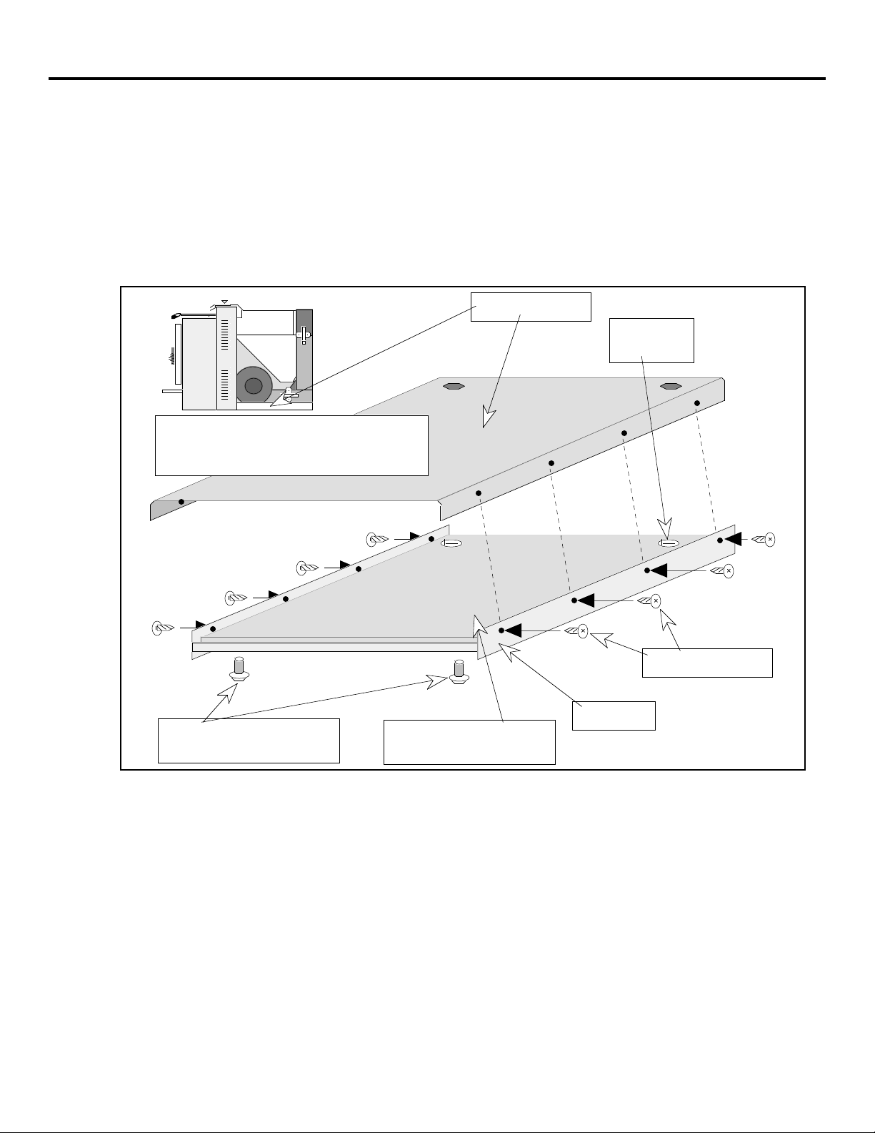
C The next step is to install the floor shield kit (see the illustration below). Prop up the
front of the insert approximately one foot. Remove the front and rear leveling bolts if
they were installed. Place the floor shield underneath the insert and line up the holes on
the floor shield with the holes in the insert baseplate, making sure the insulation included
with the floor shield stays in place. Insert four screws (included with the floor shield)
through the floor shield and then screw them into the insert baseplate. These screws are
self-tapping. Repeat for the opposite side. If the front leveling bolts are needed, insert
the two leveling bolts included with the floor shield kit into the nuts on the floor shild. If
the rear leveling bolts are needed, insert the two leveling bolts included with the insert
through the floor shield and into the insert.
NOTE: The insert is attached to the top of the
insert baseplate, but for illustrative purposes
does not appear in the blown-up illustration.
Insert Baseplate
Hole for rear
leveling bolt
Attachment Screws
Floor Shield
Front Leveling Bolts
(included with floor shield kit)
Make sure the insulation is
lined up before installing.
D Install the outside air connection (if applicable).
E If the optional igniter is being used, make sure to install it now.
F The next step is to complete the wall that the insert is placed into. The non-combustible
facing must be installed to meet the requirements (non-combustible facing must extend a
minimum of 12" above the heater). Many installers prefer the 'look' of masonry around
the pellet insert and will build the insert around either tile or brick. If the installation uses
masonry, make sure to include the depth of the masonry into the installation plans.
NOTE: The 10" panel set is the smallest panel set large enough to cover the built-in cavity.
G Place the insert in its final location, making sure it is centered and that it maintains a 3"
minimum clearance to the back wall. Make sure that all the floor covering (i.e. carpeting,
vinyl floor) has been removed from underneath the insert. Attach the pellet vent and
outside air tube. NOTE: Do not pick the insert up by the hopper or any other internal
component. All joints of the pellet vent must be screwed together and sealed.
Page 27
INSERT INSTALLATION (CONT.) PAGE 27
H Install the panels and brass trim to complete the installation. Included with the floor
shield kit are two pairs of side panels. The set that are flat are used, the bent pair can be
discarded. Attach the side panels to the side bays by placing them with the magnetic strip
side up against the side bay. Read the section "Operating the Heater" prior to plugging in
the insert and operating.
VERTICAL INSTALLATION* HORIZONTAL INSTALLATION*
Flashing
3" Clearance
Approved
Ceiling Support
Joints must be
screwed together
and sealed
Framing
Wall Covering
Top Panel
(3/8" space
between top
panel and wall
covering - do
not seal)
2' Min.
3" Minimum
3/8" Space
(Do not seal)
Type "L" Vent
Optional
vertical exterior
pellet vent route
Joints must be
screwed together
and sealed
See the
notes to
the left
Support
bracket
every 5'
3"
Min.
3"
Min.
12"
Min.
Floor covering must be
removed under insert
If the termination is below the eave,
it must maintain a 2' clearance
Approved
Wall
Thimble
Floor Shield
Outside Air
2'
Min.
1'
Min.
Approved thimble
* FOR A FULL LIST OF PELLET
VENT REQUIREMENTS, SEE
THE SECTION "PELLET VENT
REQUIREMENTS" IN THE
PELLET STOVE INSTALLATION
PORTION OF THIS MANUAL
(PAGES 8 THROUGH 10).
Page 28

PAGE 28 OPERATING YOUR HEATER
BEFORE YOU BEGIN
READ THIS ENTIRE MANUAL BEFORE YOU INSTALL AND USE YOUR
NEW HEATER. FAILURE TO FOLLOW THE INSTRUCTIONS MAY RESULT
IN PROPERTY DAMAGE, BODILY INJURY, OR EVEN DEATH.
Before starting your first fire make sure you have read the section titled Safety Precautions.
Any questions should be referred to your dealer. There are two things you will need to know
before you start your first fire:
PRIMING THE AUGER
The first time you start your heater, or if you completely run out of pellets, the auger will need to
be primed by turning the heater on and turning the BURN RATE to "HIGH" for fifteen minutes.
This will allow the pellets to feed up the auger and start to fall into the firepot before you start the
heater. After this "priming" the stove can be started normally.
PAINT CURING
The first time your heater gets up to temperature you will smell the paint on the outside of the
heater curing. This is normal. We recommend that you first fire your heater outside or leave all
of the windows open for a few hours during the first fire.
A WORD ABOUT PELLETS
Your heater was designed to burn wood pellets
only. There are some facts you should know
before you buy pellets. The paragraphs below
detail the information you should know.
With the surge in popularity of pellet heaters
came the tremendous increase in pellet demand.
Because pellets are made from wood byproducts, pellet manufacturing is dependent
upon the supply of these by-products and the
quality found therein. Unfortunately, this surge
in pellet manufacturing has led to a decline in
the quality of the raw materials used to produce
the pellets.
Ideally, pellets should have a very low moisture, ash, dirt, and salt content. Some pellets do not.
Pellets should have a consistent diameter of 1/4", 5/16", or 7 mm. Pellets should also be no
longer than 1 1/2" long. Some pellets are longer. There is no real pellet monitoring agency, so
you must monitor pellet quality yourself.
We Suggest:
Buy only 3 bags of pellets before you purchase a large amount. Burn the pellets in your pellet
heater and check for these signs of poor quality pellets: clinkers develop in the air holes on the
bottom of the firepot (see the section "Maintenance Instructions"); the auger jams for no apparent
reason, and when the hopper is cleaned out, the auger runs again; there is more than one-half cup
of sawdust in the bottom of the bag of pellets; or, the pellets don't burn well on a low BURN
RATE, and it seems the AIR CONTROL has to be pulled out all the way for the pellets to burn (a
sign of wet or dirty pellets). It is best to check one brand of pellets versus another to see the
difference first-hand. The Association of Pellet Fuel Manufacturers has set the following
standards for pellets: density of at least 40 lbs. per cubic foot; 1/4" to 5/16" diameter; length no
greater than 1 1/2"; 8200 BTU's/lb.; moisture under 8% by weight; ash under 1% by weight; and,
salt under 300 parts per million.
P
P
e
e
l
l
l
l
e
e
t
t
s
s
Page 29
OPERATING YOUR HEATER (CONTINUED) PAGE 29
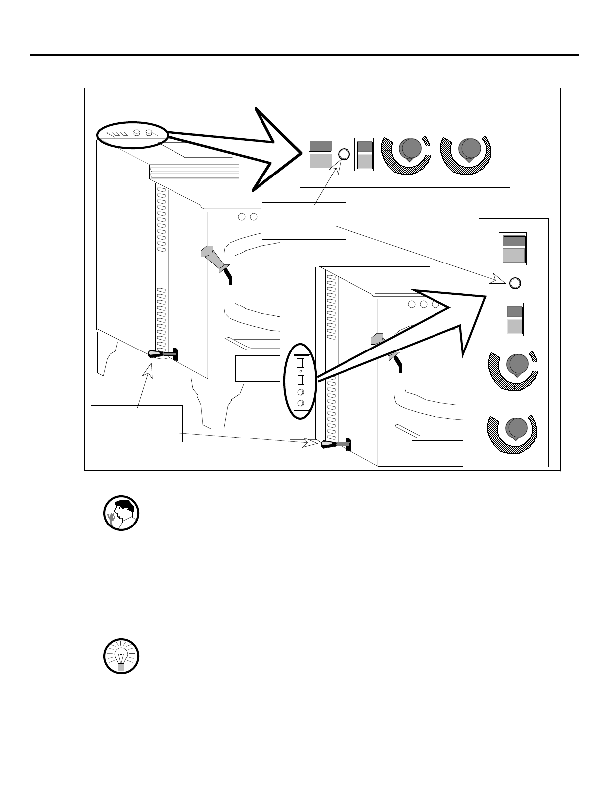
LOCATION OF CONTROLS - SEE EXPLANATION BELOW
900 PS Pellet Stove
AIR CONTROL
Knob
POWER
ON
OFF
OPERATING
Light
HIGH
OFF
BURN RATE
LOW
HIGH
LOW
FAN
START
900 PI Pellet Insert
HIGH
HIGH
POWER
ON
OFF
START
OFF
BURN RATE
LOW
LOW
FAN
POWER Switch This control is used to turn the stove on and off.
WARNING: Do not unplug the heater to turn it off. This heater relies upon
electricity to push the flue gases out the pellet vent Ð unplugging it
may lead to smoke in your room.
OPERATING Light This light indicates that the stove is in operation. It will not turn on until the
POWER switch is on and the START switch is pressed. It will not turn off
until the POWER switch is turned off and the heater has cooled off.
START Switch This control starts the heater. It will need to be pressed each time the heater
is re-started.
BURN RATE Dial This dial controls the amount of pellets that are fed into the firepot and
hence the amount of heat. This dial must be used in conjunction with the
AIR CONTROL to operate the heater correctly.
HINT: Adjust the BURN RATE and AIR CONTROL together. The higher the
BURN RATE the farther out the AIR CONTROL should be.
FAN Dial This dial controls the amount of heated air that is blown out of the heat
exchange tubes above the door. Generally, the higher the BURN RATE the
higher the FAN dial should be set.
AIR CONTROL Knob This controls the amount of air entering the firepot (see the Hint above).
Out is more air, in is less air.
Page 30

PAGE 30 OPERATING YOUR HEATER (CONTINUED)
STARTING YOUR HEATER
(MAKE SURE THE AUGER IS
PRIMED - PAGE 28)
A Pull the AIR CONTROL all the way
out to the fully open position.
B Turn the BURN RATE to a
"Medium" setting.
FF
OOOOFFFFFF
HH
HH
II
II
GG
GG
HH
HH
WW
WW
OO
OO
LL
LL
C Press the POWER button to "ON".
D Press the START switch. You will
see the light next to the POWER
button turn on and pellets start
dropping into the firepot. The
heater will self-start in 5 to 7
minutes.
E Wait fifteen minutes for the heater
to get up to temperature before
adjusting the controls.
SSSSTTTTAAAARRRRTT
PPPPOOOOWWWWEEEERR
NN
OOOONN
FF
OOOOFFFFFF
TT
BBBBUUUURRRRNNNN RRRRAAAATTTTEE
RR
55
111155
mmmmiiiinnnnuuuutttteeeess
EE
ss
Page 31
RUNNING YOUR HEATER
Your pellet heater is a high efficiency heater designed to burn over a wide range of heat output.
This wide range of heat output, along with the different variety of pellets, requires the operator to
know how to adjust the heater to achieve the most efficient burn.
Step 1: Adjust the BURN RATE
After the heater has run for 15 minutes, the BURN RATE dial can be adjusted to suit the amount
of heat needed. The higher the BURN RATE is set, the faster the pellets will feed into the
firepot and the more heat you will receive. The exact amount of heat will vary according to the
type of pellets you are using.
NOTE: Pellets vary in the amount of heat they give off and the speed in
After the BURN RATE is set, the AIR CONTROL will need to be checked.
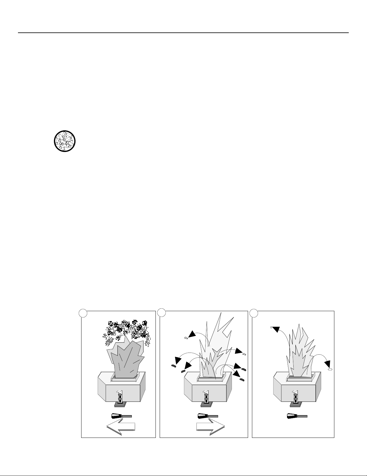
Step 2: Adjust the AIR CONTROL
The AIR CONTROL adjusts the amount of air entering the firepot. It is extremely important to
adjust it correctly. It must be adjusted every time the BURN RATE is changed or when using
different pellets. With the BURN RATE set to a particular setting, look into the firepot and check
the flame. Ideally, the pellets should be agitating slightly, with an occasional ember flying up
and a bright, jagged, yellow flame.
OPERATING YOUR HEATER (CONTINUED) PAGE 31
which they feed. Drier, cleaner pellets give off more heat. Smaller
length pellets feed faster than long pellets.
È If the pellets aren't moving and no embers are jumping out of the firepot, and the
flame is dark orange with black tips (see drawing "A" below), pull the AIR
CONTROL out 1/2". Check again.
È If the pellets are moving vigorously with many burning pellets are jumping out of
the firepot (see drawing "B" below) push the AIR CONTROL in 1/2". Check again.
È If the pellets are moving slightly with some embers jumping out of the firepot, and
the flame is bright, jagged, and yellow, (see drawing "C" below) the AIR CONTROL
is set correctly. Generally, the higher the BURN RATE, the farther out the AIR
CONTROL must be set.
A
t
t
u
u
O
O
l
l
o
o
r
r
t
t
n
n
o
o
C
C
r
r
i
i
A
A
e
e
h
h
t
t
l
l
l
l
u
u
P
P
B
n
n
I
I
l
l
o
o
r
r
t
t
n
n
o
o
C
C
r
r
i
i
A
A
e
e
h
h
t
t
h
h
s
s
u
u
P
P
C
g
g
n
n
i
i
t
t
t
t
e
e
S
S
l
l
o
o
r
r
t
t
n
n
o
o
C
C
r
r
i
i
A
A
d
d
o
o
o
o
G
G
k
OOk
Page 32

PAGE 32 OPERATING YOUR HEATER (CONTINUED)
NOTE: Every bag of pellets you use may be different. Certain pellets will be
heavier and won't want to move around in the firepot. Some pellets
will be wet, and take longer to burn. While other pellets will be
"dirtier" and produce a darker smoke. Pellets will even vary from
bag to bag. If uncertain on where to set the AIR CONTROL, it is best
to pull the AIR CONTROL out too far then to push it in too far.
HINT: Generally, the label on the AIR CONTROL should be showing RED
on HIGH, ORANGE on MEDIUM, and YELLOW on LOW.
Step 3: Adjust the FAN Dial
The Fan dial controls the amount of heated air that is blown out of the heat exchange tubes above
the door. Generally, the higher the BURN RATE the higher the FAN dial should be set.
TURNING OFF THE HEATER
To turn the heater off, switch the POWER button to "OFF".
WARNING: Do not unplug the heater to turn it off. This heater relies upon
electricity to push the flue gases out the pellet vent Ð unplugging it
may lead to smoke in your room.
POWER
ON
OFF
NORMAL OPERATING SOUNDS
Heat Exchanger Tubes
You will hear air being forced
through these tubes by the
convection fan.
Convection Fan
The modern high
efficiency fan may have
a hum or pulsating
sound, particularly on
the "HIGH" setting. This
sound may change as
the FAN dial is varied.
Firepot
As pellets are fed to the
firepot, a light clicking
sound may be heard.
Control Box
This part can produce a
clicking sound as it turns
the auger motor on and off.
Auger Motor
When feeding pellets
you may hear the
intermittent buzz of
this motor running.
Exhaust Fan
The flow of exhaust gases
through this air-cooled
induction motor creates a
steady low-pitched hum.
Page 33

MAINTENANCE SCHEDULE
Your heater requires periodic maintenance to run. The steps involved with maintenance are
usually quick and easy. Look through this maintenance schedule and plan accordingly.
WARNING: Failure to maintain your heater will lead to a restricted combustion
Daily Maintenance (when the heater is in use):
¥ Check the Firepot (Clean if Necessary)
¥ Check the Ashpan for Flyash (Clean if Necessary)
Weekly Maintenance:
¥ Clean the Heat Exchanger Tubes
¥ Clean the Firebox and Glass
¥ Clean the Ash Traps
1,000 Pound Maintenance (every 25 Bags):
¥ Clean the Hopper and Auger Tube
6,000 Pound or Yearly Maintenance (depends upon pellet quality)
¥ Clean the Exhaust Ducts
¥ Exhaust Blower
¥ Convection Blower
¥ Pellet Vent
MAINTENANCE INSTRUCTIONS
Check the Firepot (Clean if Necessary)
Look for a
dark area in
the firepot
MAINTAINING YOUR HEATER PAGE 33
air system, which may lead to smoke spillage into the room.
At least once a day while the heater is in use, look down
into the firepot and check for any dark areas where the
pellets refuse to light or glow. If this occurs, you will
need to turn the heater off and remove any buildup on the
firepot holes. You may find a piece of hardened ash that
covers the holes in the firepot (a clinker) that will need to
be removed. When replacing the firepot, make sure you
insert it correctly, otherwise air will go around the firepot
instead of through it.
To clean the firepot, first slide
the clip on the firepot holder
up and pull the firepot and
holder out of the heater. The
firepot can be slid out of the
firepot holder (make sure to
re-install it in the same
position) for cleaning. Make
sure all of the holes in the
Firepot
Holder
Firepot
The grate in the
bottom of the firepot
must be kept clean
for proper burning.
Slide this clip up
to remove the
firepot holder.
grate on the bottom of the
When re-installing,
make sure the clip
slides into this slot.
firepot are clean. Clean out
any flyash in the firepot
holder before re-installing.
HINT: If clinkers build up every day in your heater, you will want to check
for air leaks (See the section "Air Leaks") and your pellets (See the
section "A Word About Pellets"). Also, clinkers build up more often
at a low BURN RATE than at a high BURN RATE.
Page 34

PAGE 34 MAINTAINING YOUR HEATER (CONTINUED)
Check the Ashpan for Flyash
At least once a day while the heater is in use, look down through the window and check for
flyash buildup in the ashpan. If you see more than 1" of flyash, turn the heater off, wait for it to
cool and empty the ash. To empty the ashpan, turn both of the handles located under the ash lip
1/4 turn so the lines on the knobs are pointing up. Then pull the ashpan out, tilting it forward to
prevent ash from spilling off the back. Store the ash in an air tight metal container placed on a
non-combustible surface until thoroughly cooled before disposing.
NOTE: Certain pellets produce more ash than others. After a couple of days
you should know when you will need to clean the ashpan.
Ashlip (below door)
Rotate both of the handles 1/4 of a
turn upwards to remove the ashpan.
WARNING: When re-attaching the ashpan, make sure it is fully inserted before
turning the knobs 1/4 of a turn outwards. If there is not an air tight
seal, there may be smoke spillage into the room.
Clean the Heat Exchanger Tubes
Be careful when removing the ashpan
not to spill ashes off of the back.
At least once a week the heat exchanger tubes should
be cleaned. With the door closed, push the built in
cleaner located above the door back and forth a
couple of times. Wear a glove or use the tool
included with this heater if the handle is hot. You
should see flyash falling from the roof of the firebox.
After cleaning, you may wish to brush any loose
flyash into the ashpan. Cleaning the heat exchangers
allows for better heat transfer.
Clean the Firebox and Glass
At least once a week the firebox will need cleaning to remove flyash that may build up around
the firepot and hamper efficient burning. If there is an optional log set, remove the log set and
brush it clean of flyash. Then brush all flyash off of the firebrick refractory and off the walls of
the firebox. When done brushing off the flyash, clean out the flyash built up in the ashpan. The
glass should be cleaned with a non-abrasive glass cleaner. This will increase the amount of light
and heat given off by the heater, as well as add to its attractiveness.
HINT: We STRONGLY SUGGEST you buy a vacuum built specifically
for cleaning pellet heaters. These vacuums are fire-resistant and
make cleaning much easier. Because your heater is more efficient
when kept clean, this vacuum will pay for itself in fuel costs.
Page 35

Clean the Ash Traps
MAINTAINING YOUR HEATER (CONTINUED) PAGE 35
At least once a week the ash traps should be
cleaned. They are used to catch the flyash
Remove the
firepot & holder
Ash trap doors
(4 total)
before the exhaust gases exit the firebox. The
ash trap doors provide access to the ash traps
for flyash removal. First remove the firepot
and holder and empty the ashpan. Locate the
four ash trap doors located along the bottom of
the firebox. Remove them by swinging them
out and sliding them up and out. All the flyash
behind the doors can then be cleaned out. Use
a vacuum cleaner to remove the flyash or
brush the flyash onto the floor of the firebox
and remove from there. Make sure the ash
trap doors lay flat against the surrounding
metal when re-installed.
Remove the
ash trap doors
HINT: The more often you clean out the flyash, the more efficient your
heater will burn.
Clean the Hopper and Auger Tube
Front
Auger Tube
Hopper
Pay close attention
to removing all
sawdust and debris
from the bottom of
the auger tube.
First swing
it out
Then slide it
up and out
Clean out all of
the area behind
the ash trap doors
The hopper and auger tube
should be cleaned every 1,000
pounds of pellets burned. If
you notice more than 1/2 cup of
sawdust in the bottom of a bag
of pellets, the hopper and auger
should be cleaned every 500
pounds of pellets burned.
Vacuum around the hopper and
in the exposed portion of the
auger tube. Pay close attention
to getting any sawdust or debris
out of the bottom of the auger
tube. For inserts, accessing the
hopper is more difficult. Use
an extension on the vacuum to
remove all debris.
Page 36

PAGE 36 MAINTAINING YOUR HEATER (CONTINUED)
HINT: This following sections detail difficult maintenance procedures that
we strongly suggest be carried out by a TRAINED SERVICE
TECHNICIAN, possibly by a service agreement set up by the dealer.
Clean the Exhaust Ducts
The exhaust ducts are located inside the firebox and are used to transfer heat. Every 6,000
pounds of fuel the flyash and soot from behind the exhaust ducts will need to be removed
(perhaps more often depending on pellet quality). Remove the ash trap doors by following the
directions in the section "Clean the Ash Traps". Remove the firebrick refractory by lifting it up
and away from its holder on the back of the firebox. This will expose the two clean-outs on the
back wall of the firebox. Remove these clean-outs, as well as the clean-outs on each side, by
prying loose with a screwdriver. Tap against the exhaust ducts to remove the loose flyash first.
Then brush away any soot or flyash that has built up behind the exhaust ducts. Use a piece of
wire to reach the areas inside the exhaust ducts that are hard to reach. The soot and flyash will
fall down to the ashtrap area. Vacuum out all of the flyash and soot. Replace the clean-outs,
firebrick refractory, and firepot holder when finished cleaning.
Remove the firebrick
refractory by lifting it
up and pulling it
towards the door
Pry the
clean-outs
out with a
screwdriver
Clean behind
the exhaust
ducts with a
piece of wire
ACCESSING INTERNAL COMPONENTS
FOR STOVES:
The internal components on a pellet stove are accessed by opening either of the hinged side
panels. Before opening the panels, turn the stove off and let it cool for one hour. Remove the
power cord from the electrical socket. For the left side panel the air control knob must be
unscrewed. Open either of the side panels by taking a standard screwdriver and turning the two
fasteners one-quarter turn. These fasteners hold the panel in place, and only need to be turned
slightly to release. Then swing the panel back on the hinge. To re-attach, turn the fasteners onequarter turn while pressing them against their sockets.
Left Panel
Fasteners (Turn
1/4 revolution
with standard
screwdriver)
To Remove, Twist and Pull
Left
Panel
Hinge
If opening the left
panel, unscrew
the air control
knob first.
To Fasten, Push and Twist
Page 37

MAINTAINING YOUR HEATER (CONTINUED) PAGE 37
FOR INSERTS:
The internal components on either side of the insert are accessed by pulling the insert out of the
fireplace. Turn the insert off and let it cool for one hour. Remove the power cord from the
electrical socket. Lift off the brass trim around the surround panels and then slide off the top
surround panel. Reach in above the insert and disconnect the pellet vent where it attaches to the
insert (make sure to re-seal with RTV 500o F. silicone). Put down a piece of cardboard on the
hearth to prevent scratching. Then remove the door and draw the insert out by pulling from the
door opening (pulling from the hopper area may damage the insert). With the insert drawn out
onto the hearth the internal components can be accessed. Follow these directions in reverse order
to re-install the insert.
Convection Blower
The convection blower pushes air through the heat exchanger tubes, transferring heat from within
the firebox to the room. Over time it will collect dirt and need cleaning.
The first step is to
Hopper
Electrical Leads
From Control Box
to Switch Box
Combustion Air Duct
Convection
Blower
Control Box
Convection Blower
Electrical Leads
open the left side
panel (follow the
directions in the
section
"ACCESSING
INTERNAL
COMPONENTS").
Disconnect the two
power leads going to
the convection
blower. The
orientation of these
two wires does not
matter when reattaching them.
Clamp
Use a 7/16" wrench
or socket driver to
remove this nut
Use a 7/16" socket wrench to
remove the single nut located at
the top of the convection
blower. The convection blower
can now be pulled out of the
unit for cleaning. Clean off any
dirt that has attached to the
intake screen on the blower.
Tap against the blower to
dislocate any dirt from inside
the blower and shake the dirt
out. Check the impeller blade
and brush off any dust or soot.
If it is damaged, replace the
blower. Follow the directions
in reverse order to re-attach the
convection blower.
Page 38

PAGE 38 MAINTAINING YOUR HEATER (CONTINUED)
Exhaust Blower
The exhaust blower pulls the combustion air through the heater and pushes the flue gases out the
pellet vent. It collects soot and must be cleaned every 3 tons of fuel burned. Follow the
directions in "ACCESSING INTERNAL COMPONENTS" for accessing the right side. For
stoves, remove the pellet vent connection at the back of the stove (make sure to re-seal with RTV
500o F. silicone).
Make sure the heater is unplugged, then disconnect the two power leads going to the exhaust
blower. The orientation of these two wires does not matter when re-attaching them. Use a 3/8"
nut driver to remove the four mounting nuts that hold the exhaust blower in place. Three of the
nuts are located on top of the exhaust blower while one is on the lower left and can only be
accessed through a hole in the base. Remove the insulation surrounding the exhaust blower. Tilt
the exhaust blower outwards and slide towards the side to remove. With the exhaust blower
removed, check the gasketing that insulates the connection between the exhaust blower and the
exhaust housing. Replace the gasket if it has deteriorated. Follow the directions in reverse order
to re-attach the exhaust blower. Make sure to re-seal the pellet vent connections with RTV 500
F. silicone.
Exhaust
Housing
o
Exhaust Blower
(Lined with
Insulation)
Power Leads to
Exhaust Blower
Mounting Nuts
Exhaust Blower
Once the exhaust blower is removed, place it so the side that holds the gasket is up. Check the
impeller blades for any damage and replace if necessary. Clean the inside of the blower, making
sure to get the soot up inside the blower. Check the silicone seal where the blower connects to
the exhaust tube. Use RTV 500o F. silicone to reseal the joint. Use a new exhaust gasket if the
existing one is torn or significantly worn.
Make sure the flow switch
nipple is not clogged
(check both ends)
Clean the
inside of the
exhaust
housing
Check
Silicone
Seal
Exhaust Tube
Insulation
Clean up
inside the
blower
Page 39

Pellet Vent
Wind/Rain Cap
Tee with Clean Out Cover
Attachment to
Pellet Heater
MAINTAINING YOUR HEATER (CONTINUED) PAGE 39
Pellet Vent Sections
Check the pellet vent for soot and creosote
build-up, and have it cleaned by a certified
chimney sweep if necessary.
The wind/rain cap should be cleared of any
dirt or debris. The pellet vent sections
should be inspected for soot and creosote
build-up. Any build-up over 1/4" must be
removed.
On stoves the dirtiest portion is often the
point where the vent turns upwards. The
elbow, center flue adapter, or "Tee" section
on vertical pellet vent systems has the most
build-up. Fortunately, the "Tee" and
center flue adapter have a built in clean out
cover. Simply remove the cover and
vacuum out. While open, use a flashlight
to look up the pellet vent to check for
build-up.
On inserts the dirtiest portion is often the
portion where the pellet vent turns upward.
Fortunately, this portion can often be
accessed by unclipping the vertical exhaust
extender (see "Insert Installation").
HINT: The more often you clean out the pellet vent, the more efficient your
heater will burn. Furthermore, you will reduce the chance for any
smoke spillage due to a clogged pellet vent system.
WARNING: Failure to clean the pellet vent system will lead to smoke spillage
into the room. Furthermore, whenever any portion of the pellet vent
is disconnected, the joints must be sealed with RTV 500o F. silicone
sealant.
Page 40

PAGE 40 TROUBLESHOOTING
Problem: Possible Cause: Don't Call for Service
Heater won't start
(Operating light won't
turn on)
Heater not plugged in
Power button not turned "ON or start button pressed
Power supply cut
Fuse blown
Until You:
Plug the heater in
See "Starting Your Heater"
Check household fuse/breaker
See "Fuse Blown" below
Firepot overfills on startup
Fire starter extinguishes
soon after lighting
Lazy and dark orange
flame with black smoke
Exhaust is smoky, but the
flame is okay
Firepot overfills with
pellets
Pellets not feeding
Fire starter was lit with the BURN RATE on "HIGH"
Fire starter did not fully ignite
AIR CONTROL was not pulled out after the BURN RATE
was set to "HIGH"
Heater was not turned on and the start button pressed
AIR CONTROL was pulled all the way out while the fire
starter was just starting to burn
AIR CONTROL is set too low
Firepot is plugged
Pellets are bad
Exhaust ducts are clogged
Air leak
Exhaust system is clogged
Heater was just started
Pellets are bad
AIR CONTROL is too far in
Firepot is plugged
Air leak
Exhaust ducts are clogged
Exhaust system is clogged
Auger not primed
Pellets have run out
Power button not turned "ON or start button pressed
Power supply cut
Fuse blown
Auger flight jammed
Power outage
Pellet Vent Blocked
See "Starting Your Heater"
See "Starting Your Heater"
See "Starting Your Heater"
See "Starting Your Heater"
See "Starting Your Heater"
See "Operating Your Heater"
See "Check the Firepot"*
See "Poor Quality Pellets" below
See "Clean the Exhaust Ducts"*
See "Air Leaks" below
See "Exhaust Blower "*
This may occur and is not unusual
See "Poor Quality Pellets" below
See "Operating Your Heater"
See "Check the Firepot"*
See "Air Leaks" below
See "Clean the Exhaust Ducts"*
See "Exhaust Blower"*
See "Starting Your Heater"
Refill hopper with pellets
See "Starting Your Heater
Check the household fuse/breaker
See "Blown Fuse" below
See "Jammed Auger" below
Wait until power is restored
See "Safety Features" below
Smoke smell in room
(Do not unplug, flip the
POWER switch to "OFF")
Heater turned off when
hopper is full
Fire goes out on low burn.
Auto-Ignition System does
not start the heater.
* In the section "Maintenance Instructions" starting on page 33.
Momentary power outage
Flue not sealed
Automatic safety feature has shut off stove
Flue system on insert version not fully sealed
Power outage
Automatic safety feature has shut stove off
Auger jammed
AIR CONTROL too far out
Air leak
Burn Rate set too low
AIR CONTROL in too far
This is normal - see "Safety Features"
See "Installation Instructions"
See "Safety Features" below
See "Installation Instructions"
See "Safety Features"
See "Safety Features"
See "Jammed Auger" below
See "Operating Instructions"
See "Air Leaks" below
See "Starting Your Heater"
See "Operating Your Heater"
Page 41

TROUBLESHOOTING (CONTINUED) PAGE 41
Air Leaks
If air leaks into the firebox from the door or ashpan not properly closing, the amount of air
flowing through the pellets will decrease. A good way to simulate an air leak is to open the door
just a crack while the heater is burning. You will notice that the flame gets very lazy and the
brightness decreases. Your efficiency with an air leak is very poor, flyash will increase, and the
glass generally becomes dirty. If your heater has a lazy, smoky flame or the pellets are stacking
up in the firepot and the AIR CONTROL is all the way open, you should first check for a plugged
firepot and then for an air leak.
Check the following two areas for an air leak.
Ashpan Check the ashpan seal by pushing against it on either side to see if it rocks. If
your ashpan can rock, you may need a new ashpan gasket. Another way to test
the seal is to run a lit match around the perimeter of the ashpan while the heater
is running. If there is an air leak, the flame will bend towards the leak.
Door To check the door seal, inspect the gasket around the door to see if it seals
against the face of the heater. If it does not, the door may need to be aligned or
the door gasket may need to be replaced. Another way to test the seal is to run a
lit match around the perimeter of the door while the heater is running. If there is
an air leak, the flame will bend towards the leak.
Jammed Auger
Augers can jam when an especially long and hard pellet gets caught, if the pellets are allowed to
back-up the feed tube, or if a piece of debris is allowed into the hopper (a nail or screw
especially). To check if the auger is jammed, clean and vacuum out the hopper. Turn the heater
on and turn the BURN RATE to "HIGH". Look into the hopper and check to see if the auger is
turning. If it is not, it could be jammed. Check for debris (e.g.: a screw or nail) caught at the
mouth of the auger tube opening. On inserts the hopper cover may need to be removed to check
for debris. If there is nothing there, insert a piece of large wire up the feed tube and poke it
around to dislodge any pellets stuck at the top of the auger tube. If pellets are lodged at the top
of the auger tube, the wire will dislodge them and they will fall out the feed tube.
Auger Tube
Hopper
Pay close attention
to removing all
sawdust and debris
from the bottom of
the auger tube.
For inserts, the
hopper cover
may need to be
removed to
check for caught
debris.
Front
Check for debris
caught here
Hopper Lid
Two Phillips-Head
Screws (Accessed
with hopper lid open)
Three
Phillips-Head
Screws
Insert a piece of
large wire up the
feed tube and
poke it around
to dislodge any
stuck pellets
VIEW FROM TOP
FRONT
HOPPER
COVER
Page 42

PAGE 42 TROUBLESHOOTING (CONTINUED)
Fuse Blown
Make sure the heater is fully cooled and unplugged. Check the fuse by opening the left side
panel (see the section "ACCESSING INTERNAL COMPONENTS" in the maintenance portion
of this manual) and pulling out the fuse located on the control box. If the fuse has blown, it
means a short has occurred, and your dealer should be called. Do not operate your heater until
the reason for the blown fuse has been determined and fixed. It may have been a simple power
surge or it may be a dangerous short inside your heater.
5 Amp Fuse
Control Box
Electrical Leads
From Control Box
to Switch Box
Poor Quality Pellets (also see the section "A Word about Pellets")
Check for poor quality pellets by burning different brands (usually 3 bags will give you a good
indication). High quality pellets will not only burn better, but produce more heat. The extra cost
for high quality pellets is worth it.
Bags of pellets should never be left uncovered outside. The plastic bag around the pellets should
not be considered air or water tight. Pellets are usually thoroughly dried before bagging. So if
the bag is exposed to damp conditions, the pellets will actually absorb water from the air.
Safety Features
Your heater has built in safety systems which may shut the heater off even though the heater has
pellets and the POWER button is "ON".
Power Outages. During a power outage the heater will shut down unless the power
outage is just momentary, in which case it will remain on if there is sufficient heat
to keep burning.
Overheating. If your heater overheats the auger will shut off and no longer feed pellets.
This will allow the heater to cool down safely. The heater will not restart until it
has cooled sufficiently. If this happens frequently, turn the unit off and consult
with your dealer to determine the problem.
Blocked Flue or Down Draft. This heater is equipped with a draft sensor. If a
restriction or back draft occurs, the heater will automatically shut itself off. If the
restriction or back draft is momentary, it will automatically resume operation. If
the restriction is permanent, the heater will not start until the restriction is fixed.
Page 43
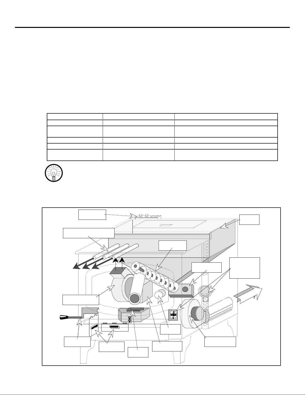
TROUBLESHOOTING (CONTINUED) PAGE 43
How this Pellet Heater Works
This pellet heater is a combination of four systems working together to burn pellets and transfer
the heat to your room. Your heater will only burn when there is an acceptable amount of air,
pellets, and heat present in the firepot. Air is supplied through the Combustion Air/Exhaust
System. Pellets are supplied through the Pellet Feed System. Heat comes from combustion and
is transferred to the room through the Convection Heat System. The last system is the Safety
System. If any one of these systems does not work right, your heater will not operate correctly.
When troubleshooting any problem with your stove, it is easiest to determine which system is
working incorrectly and then go through each component of that system until the problem is
found. The tables below lists the major components of each system and tips for troubleshooting
your heater (see the illustration below for each component's location and appearance).
Combustion Air/Exhaust System
Consists of: Purpose: Troubleshooting Tips
Air Inlet Provides air for combustion Aluminum duct not crushed or blocked
AIR CONTROL Adjusts the amount of air going
to the firepot
Firepot Hold pellets during combustion Holder on correctly, no clinkers, no air leaks
Ash Traps Trap flyash Cleaned out and on correctly
Exhaust Blower Pull air through firepot and push
flue gases out flue
Slides in and out
Cleaned out
HINT: This system is the hardest to troubleshoot and crucial to the heater's
operation. It must be air-tight through the entire chain of
components. The most common problem is an air leak into the
firebox. This will rob air from the firepot, making combustion
incomplete (leading to more soot, more smoke, less heat, and overfeeding).
Switch Box
Hopper
Heat Exchanger Tubes
Auger Tube
Electronic
Auger Motor
Convection Fan
Safety
Components
Exhaust
Air Control
Ash Traps
Air Inlet
Exhaust Fan
Control Box
Firepot
Page 44

PAGE 44 TROUBLESHOOTING (CONTINUED)
Pellet Feed System
Consists of: Purpose: Troubleshooting Tips
Hopper Stores pellets Debris caught in mouth of auger tube
Auger Motor Turns the spiraled auger flight Not user serviceable*
Auger Tube Pushes pellets to feed tube See the section "Jammed Auger"
Switch Box Determines the feed rate Not user serviceable*
Control Box Turns the auger on and off Not user serviceable*
Convection Heat System
Consists of: Purpose: Troubleshooting Tips
Convection Blower Pushes air into heat exchanger
tubes
Heat Exchanger Tubes Draws the heat off of the fire Not user serviceable*
Switch Box Determines the convection
blower speed
Electronic Safety System
Consists of: Purpose: Troubleshooting Tips
Electronic Safety
Components
Turns the heater off for a blocked
flue or overheating
HINT: This system is of utmost importance. Components should only be
serviced by trained technicians. Call your dealer if there are any
questions.
Cleaned out
Not user serviceable*
Not user serviceable* (see the section
"Automatic Safety Features")
* These components can only be tested by replacing with a new component.
Replacement Parts
Ashpan Ashpan Gasket
Ashpan Handle Auger Motor
Auto-Ignition System Assembly Ceramic Log with Bracket
Control Box Convection Blower
Door Gasket Door Handle
Exhaust Blower Exhaust Blower Gasket
Exhaust Tube Gasket (Inserts Only) Firebrick Refractory
Firepot Flow Switch
Flow Switch Tube Glass
Glass Gasket Fuse (5 Amp Quick-Blow)
Switch Box -- Freestanding
120o F. Snap Disk SPDT - N.C. (System)
Switch Box -- Insert
120o F. Snap Disk SPST - N.O. (Convection Blower)
200o F. Snap Disk SPST - N.C. (Hopper)
Page 45

WARRANTY PAGE 45
To register your TRAVIS INDUSTRIES, INC. Limited Lifetime Warranty, complete the enclosed warranty card and mail it within ten
(10) days of the appliance purchase date to: TRAVIS INDUSTRIES, INC., 10850 117th Place N.E., Kirkland, Washington 98033.
TRAVIS INDUSTRIES, INC. warrants to the original purchaser that the AVALON pellet appliance be defect-free in material and
workmanship from the date of purchase as follows:
YEAR 1-COVERAGE: PARTS & LABOR -
1. Stove body, igniter, auger flight, auger tube, auger bearings, all other component parts & all accessories are covered for one year (ceramic glass,
refractory brick and logs are covered for thermal breakage only). Cost of any warranted component parts and labor to replace or repair warranted
component parts are covered. The cost of the dealer service call or travel time is not covered. Paint & gasketing material are excluded from coverage.
2. One-way freight allowance on pre-authorized repair done at factory is covered.
3. In cases where stove must be removed from home for repairs, a partial cost of re-installation of stove is covered (pre-authorization required).
YEAR 2-COVERAGE: PARTS & LABOR -
1. Stove body, igniter, auger flight, auger tube, auger bearings and all other component parts are covered (ceramic glass, refractory brick and logs are
covered for thermal breakage only). Cost of any warranted component parts and labor to replace or repair warranted component parts are covered. The
cost of the dealer service call or travel time is not covered. All accessories, electrical components, paint & gasketing material are excluded from coverage.
2. One-way freight allowance on pre-authorized repair done at factory is covered.
3. In cases where stove must be removed from home for repairs, a partial cost of re-installation of stove is covered (pre-authorization required).
4. Any of the above excluded component parts may be purchased at 30% discount off suggested list price.
5. New or replacement accessories are not available at discount prices.
YEARS 3-5-COVERAGE: PARTS & LABOR -
1. Stove body, auger flight, auger tube and all other component parts are covered. Cost of any warranted component parts and labor to replace or repair
warranted component parts are covered. The cost of the dealer service call or travel time is not covered. All accessories, igniter, electrical
components, ceramic glass, firebrick & logs, paint, and gasketing material are excluded from coverage.
2. Any of the above excluded component parts may be purchased at 30% discount off manufacturerÕs suggested list price (plus any shipping and
handling charges from your local dealer).
3. New or replacement accessories are not available at discounted prices.
4. One-way freight allowance on pre-authorized repair done at factory is covered.
5. No re-installation coverage.
YEARS 6 & ON-COVERAGE -
1. The original purchaser can buy stove component parts at 30% discount off suggested retail (plus any shipping & handling charges from your local
dealer) as long as you own the appliance (but a maximum of 5 years after Travis Industries discontinues the designated model).
2. The solid brass door is warranted to not warp, crack or peel for as long as you own the appliance. This warranty does not cover tarnishing of the brass
finish . Overfiring or neglect can cause permanent discoloration not covered under warranty (See OwnerÕs Manual for proper care).
3. The stainless steel ÒForgeÓ burn pot is warranted against Òburn throughÓ for as long as you own the unit (shipping and handling are not covered).
4. Auger tube and auger flight are warranted against defects in material or workmanship for as long as you own the unit.
5. New or replacement accessories not available at discounted prices.
6. No coverage on stove body, component parts or labor.
7. No freight allowances or re-installation coverage.
CONDITIONS & EXCLUSIONS
1. This new AVALON pellet appliance must be installed by a competent authorized service contractor. It must be installed and operated at all times in
accordance with the installation and operation instructions spelled out in the OwnerÕs Manual. Any alteration, willful abuse, accident, or misuse of
the product shall nullify this warranty.
2. This warranty is nontransferable, and is made to the ORIGINAL purchaser, provided that the purchase was made through an authorized AVALON dealer.
3. Discoloration and some minor movement of certain parts is normal and not a defect and, therefore, not covered under warranty. Overfiring of this
appliance can cause serious damage not covered under warranty and it is the responsibility of the installer to ensure that the appliance is burning as
per rating tag at time of installation.
4. The warranty as outlined within this document does not apply to the chimney components or other non-Travis accessories used in conjunction with the
installation of this product. If in doubt, contact your Authorized AVALON retailer before installation. Travis Industries will not be responsible for...
a. Down draft or smoke spillage caused by environmental conditions such as nearby trees, buildings, roof tops, hills or mountains.
b. Inadequate ventilation or negative air pressure caused by mechanical systems such as furnaces, fans, clothes dryers, etc.
5. Exclusions to this Limited Lifetime Warranty include: injury, loss of use, damage, failure to function due to accident, negligence, misuse, improper
installation, alteration or adjustment of the manufacturer's settings of components, lack of proper and regular maintenance, damage incurred while the
unit is in transit, alteration, or act of God.
6. This limited warranty excludes damage caused by normal wear and tear, such as paint discoloration or chipping, worn or torn gasketing, firebrick &
logs breaking, etc. Also excluded is damage to the unit caused by abuse, improper installation, modification of the unit or the use of fuel other than
wood pellets. Damage to the solid brass finish caused by fingerprints, scratches, items melted to the face, or other external material left on the solid
brass or from the use of abrasive cleaners is not covered in this warranty.
7. TRAVIS INDUSTRIES, INC. is free of liability for any damages caused by the appliance, as well as inconvenience expenses and material. Incidental
or consequential damages are not covered by this warranty. In some states, the exclusion of incidental or consequential damage may not apply.
8. This warranty does not cover any loss or damage incurred by the use or removal of any component or apparatus to or from the AVALON pellet
appliance without the express written permission of TRAVIS INDUSTRIES, INC. and bearing a TRAVIS INDUSTRIES, INC. label of approval.
9. Any statement or representation of AVALON products and their performance contained in AVALON advertising, packaging literature, or printed
material is not part of this limited warranty.
10. This warranty is automatically voided if the applianceÕs serial number has been removed or altered in any way. Only the original purchaser of An
Avalon appliance is covered by this warranty. If the appliance is used for commercial purposes, it is excluded from this warranty.
11. No dealer, distributor, or similar person has the authority to represent or warrant AVALON products beyond the terms contained within this warranty.
TRAVIS INDUSTRIES, INC. assumes no liability for such warranties or representations.
12. THIS LIMITED LIFETIME WARRANTY IS THE ONLY WARRANTY SUPPLIED BY TRAVIS INDUSTRIES, INC., THE MANUFACTURER
OF THE APPLIANCES. ALL OTHER WARRANTIES, WHETHER EXPRESS OR IMPLIED, ARE HEREBY EXPRESSLY DISCLAIMED AND
PURCHASERÕS RECOURSE IS EXPRESSLY LIMITED TO THE WARRANTIES SET FORTH HEREIN.
IF WARRANTY SERVICE IS NEEDED...
1. If you discover a problem that you believe is covered by this warranty, you MUST REPORT it to your AVALON dealer WITHIN 30 DAYS, giving
them proof of purchase, the purchase date, and the model name and serial number.
2. Travis Industries has the option of either repairing or replacing the defective component.
3. If your dealer is unable to repair your applianceÕs defect, he may process a warranty claim through TRAVIS INDUSTRIES, INC., including the name
of the dealership where you purchased the appliance, a copy of your receipt showing the date of the applianceÕs purchase, and the serial number on
your appliance. At that time, you will be asked to ship your appliance, freight charges prepaid, to TRAVIS INDUSTRIES, INC. TRAVIS
INDUSTRIES, INC., at its option, will repair or replace, free of charge, your Avalon appliance if it is found to be defective in material or
workmanship within the time frame stated within this limited warranty. TRAVIS INDUSTRIES, INC. will ship your appliance, freight charges (first
five years) prepaid by TRAVIS INDUSTRIES, INC., to your regional distributor, or dealership.
4. Check with your dealer in advance for any costs to you, when arranging a warranty call. Dealers may require you to pay a service or trip charges for
any warranty work. This charge can vary from store to store.
Page 46
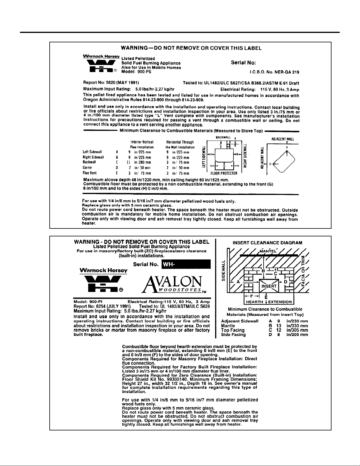
PAGE 46 PRODUCT LISTING INFORMATION
Page 47

CERAMIC LOG SET
The log set is included as standard equipment to make the pellet heater appear more like a wood
stove (it is designed for aesthetic purposes only and is not required). The instructions below
detail its installation.
1. The log is placed on a log holder at the front of the firebox. This holder slides
OPTIONAL EQUIPMENT PAGE 47
into place. Before installing the log, make sure the holder is properly located.
Back View
These
flanges
hold the log
in place.
Make sure the log holder is
pressed all the way down before
installing the log. To remove the
log holder, pull it upwards.
Spacer
Side View
Log
Holder
Burnpot
2. The log is shipped with the heater. Remove the log from its wrapping and place it
on the log holder (see the illustration below).
Log
Set
Log Holder
Make sure the log fits over the flanges
and is pushed all the way back.
HINT: Inspect the flames after installing the log set. If the flames are sooty,
try re-adjusting the log so the flames can flow around and through
the log set with less resistance. This will cut down the amount of
flyash and soot inside the pellet stove.
NOTE: Remove the log set when cleaning the heater or inspecting the burn
pot (remove the log holder if necessary).
Page 48

PAGE 48 OPTIONAL EQUIPMENT (CONTINUED)
STOVE LEGS
There are three different stove legs available for your pellet stove: cast brass; cast black; and,
black steel. The instructions for installing the legs are the same for each type of leg.
Raise the stove by inserting some pieces of lumber in the middle of the stove to a height of about
8". Line up the hole in the top of the leg with the threaded bolt hole in each corner of the stove
bottom. Using a 9/16" open end or socket wrench, fasten the leg to the stove with the supplied
attachment bolts and washers, making sure the legs are flush with the corners of the stove.
Unscrew the leveling bolts enough so the stove will rest on the upper tips, not the metal portion
of the legs. Lower the stove down.
To level the stove, lift the stove up and unscrew each leveling bolt the appropriate amount. The
rubber tips of the leveling bolts will tear if they are adjusted while weight is applied to them.
PEDESTAL
Unpack the box containing the pedestal and check for any damage. Report any damage to your
dealer.
Slide the wood trim included with the pedestal on to the front and back edge of the pedestal so it
lines up from side to side. Place the pedestal in place and lift the stove on top of it. Line up the
threaded bolt holes in the bottom of the stove with the two holes on the tabs on the inside edge of
the pedestal (see the illustration below). Using a 9/16" socket wrench, fasten the pedestal to the
stove with the supplied bolts and washers. If installing in a mobile home, the pedestal will need
to be attached to the floor. Insert the two included lag bolts through the pedestal base and screw
them into the floor with a 1/2" socket wrench.
Attach Bolt (with
washer) to Stove
From Below
Holes for attachment bolts
Attachment Bolts and
Washers - use a 9/16"
socket wrench to
attach the pedestal to
the stove.
Attach Bolt (with
washer) to Stove
From Below
If installing in a mobile home, insert
the lag bolts through the holes in the
baseplate and screw them into the
floor with a 1/2" socket wrench.
Lag Bolts
17"
23"
The faceplate of the
stove is 11/4" in
front of the pedestal
Screen, insulation, and
staples (used for wood
stoves - discard these items)
NOTE: Replace the two front bolts that hold the "hold-down brackets" into the
baseplate after the metal brackets have been removed -- This prevents air from
entering through these holes.
Page 49

CENTER FLUE ADAPTER
The center flue adapter is an optional item used to center the pellet vent on the pellet stove. It
allows for a more compact installation than using offsets on the pellet vent. To install the center
flue adapter, follow the directions below.
1. When determining the final position of the stove, take into consideration the
location of the center flue adapter once it is installed. It is best to install the center
flue adapter before determining the location of the stove, making the final
alignment with the pellet vent more accurate. The center flue adapter allows for
the use of 3" pellet vent or 6" singlewall or doublewall stovepipe. Use the
appropriate collar for the vent type used.
2. Insert the center flue adapter onto the pellet stove and align it so the length of the
adapter is vertical. On the center flue adapter where it connects to the exhaust
pipe there are three holes on the outward, top, and bottom side. Make a mark on
the exhaust tube where these holes line up. Make sure the pipe adapter is all the
way against the exhaust pipe and properly aligned when making these marks.
Take the center flue adapter off and drill a 9/64" hole where each of the three
marks where placed on the exhaust pipe.
3. Apply a high-temperature silicone sealant (type 500 degree RTV) around the
outside perimeter of the exhaust pipe near the end and slide the center flue adapter
into place. Attach the center flue adapter to the exhaust pipe by sliding it into
place and screwing in the three sheet-metal screws through the center flue adapter
and into the holes that were drilled in step 4. Inspect the connection between the
exhaust pipe and center flue adapter for an airtight seal. Apply more hightemperature silicone sealant if necessary.
4. The center flue adapter has a sheet metal bracket used to secure the center flue
adapter to the stove. It attaches to the back of the stove in two locations. Drill the
9/64" holes in the back of the stove. Drill only enough to penetrate the first layer
of metal. Screw in the remaining two sheet-metal screws with a phillips-head
screwdriver.
5. The center flue adapter can now be attached to the vent. Make sure to seal the
connection between the center flue adapter and vent with a high-temperature
silicone sealant (type 500 degree RTV).
OPTIONAL EQUIPMENT (CONTINUED) PAGE 49
Drill Three Holes for the
Screws that hold the
Center Flue Adapter to
the Exhaust Pipe
Collar for 3" Stovepipe
Collar for 6" Stovepipe
Sheet Metal Bracket Used
to Secure the Center Flue
Adapter to the Stove
Remove this Plate to Clean the Center Flue Adapter
Use the three holes on the center flue adapter to mark the
three holes that will be drilled into the exhaust pipe (make sure
the center flue adapter is vertical and fully inserted)
Page 50

PAGE 50 OPTIONAL EQUIPMENT (CONTINUED)
INSERT FRONT SUPPORT
The insert front support is used to support the insert when installed in a raised masonry or zero
clearance fireplace. The instructions below detail its installation.
Packing List:
¥ Support ¥ Support Extension
¥ 2 Screws (for Support Extension) ¥ 2 Leveling Bolts and Nuts
1. Remove the ashpan and
prop the insert up.
Remove the two bolts
located underneath the
front corners of the
insert with a 9/16" open
end wrench (these bolts
are connected to the
brackets used during
shipping). Slide the
tabs on the support into
the space underneath the
insert (see the
illustration to the right).
Attach the support to
the insert with the bolts.
2. Screw the two nuts into
the two leveling bolts
(included with the insert
front support kit). Insert
the leveling bolts into
the lower brackets on
the support and adjust
them to the approximate
height required. Place
the insert in position
and adjust the leveling
bolts to the required
height and lock the bolts
in position by tightening
the nuts against the
support.
3. Place the support
extension around the
support so that it covers
the gap between the
support and the floor.
Use a 5/16" nut driver
to attach the screw
through the elongated
hole on the extension
and into the hole on the
support.
Slide the
tabs on the
support into
this space
here.
Support
Locknut
Support
Insert a locknut onto each
leveling bolt, adjust it to the
approximate height, and
attach it to this bracket on
the inside of the support (use
a 9/16" open end wrench).
Place the support extension around the
support and use a 5/16" nutdriver to attach
the screw through the elongated hole on the
extension and into the hole on the support.
Insert
Use the bolts
removed from
the shipping
brackets to
attach the
support to the
insert.
Insert
Lock
Nut
Leveling
bolt
Support
Support
Extension
 Loading...