

Page 1
Page 2

SAFETY PRECAUTIONS
VIEWING DOOR AND ASHPAN MUST BE CLOSED
•
AND LATCHED DURING OPERATION.
THIS UNIT MUST BE PROPERLY INSTALLED IN
•
ORDER TO PREVENT THE POSSIBILITY OF A HOUSE
FIRE. FOR YOUR SAFETY THE INSTALLATION
INSTRUCTIONS MUST BE STRICTLY ADHERED TO.
DO NOT USE MAKESHIFT METHODS OR COMPROMISE INSTALLATION.
CONTACT YOUR LOCAL BUILDING OFFICIALS TO
•
OBTAIN A PERMIT AND INFORMATION ON ANY INSTALLATION RESTRICTIONS OR INSPECTION REQUIREMENTS IN YOUR AREA. ALSO, NOTIFY
YOUR INSURANCE COMPANY THAT YOU ARE INSTALLING A PELLET BURNING APPLIANCE.
THIS UNIT'S EXHAUST SYSTEM WORKS WITH A
•
NEGATIVE COMBUSTION CHAMBER PRESSURE
AND A LOW POSITIVE CHIMNEY PRESSURE. IT IS
VERY IMPORTANT THAT THE EXHAUST SYSTEM
BE COMPLETELY AIRTIGHT AND PROPERLY INSTALLED. THE CHIMNEY JOINTS SHOULD BE
SEALED WITH RTV 500 DEGREES FAHRENHEIT
(500° F) (260° C) SILICONE SEALANT. IMPROPERLY
INSTALLED STOVES ARE THE MAJOR CAUSE OF
HOME FIRES.
THE AVALON 900 APPLIANCE IS DESIGNED AND
•
APPROVED FOR THE BURNING OF PELLETIZED
WOOD FUEL ONLY. THE BURNING OF ANY TYPE
OF FUEL OTHER THAN THAT LISTED WILL VOID
ALL WARRANTIES AND THE SAFETY LISTING OF
THE UNIT. DO NOT ATTEMPT TO BURN ANY
OTHER FUEL THAN SPECIFIED IN THIS MANUAL.
THE EXHAUST SYSTEM SHOULD BE CHECKED
•
TWICE A YEAR MINIMUM FOR ANY BUILD-UP OF
SOOT OR CREOSOTE.
GASOLINE OR OTHER FLAMMABLE LIQUIDS MUST
•
NEVER BE USED TO START THE FIRE OR
"FRESHEN UP" THE FIRE. DO NOT STORE OR
USE GASOLINE OR OTHER FLAMMABLE LIQUIDS
IN THE VICINITY OF THIS APPLIANCE.
ASHES MUST BE DISPOSED OF IN A METAL
•
CONTAINER WITH A TIGHT FITTING LID, AND
PLACED ON A NON-COMBUSTIBLE SURFACE
BEFORE FINAL DISPOSAL.
THIS UNIT MUST BE CONNECTED TO A GROUND-
•
ED, STANDARD 110 VOLT, 60 HZ ELECTRICAL
OUTLET. NEVER ROUTE THE POWER CORD
UNDER OR IN FRONT OF THE UNIT.
• NEVER BLOCK FREE AIRFLOW THROUGH THE
OPEN VENTS OF THE UNIT.
NEVER TRY TO REPAIR OR REPLACE ANY PART
•
OF THE APPLIANCE UNLESS INSTRUCTIONS ARE
GIVEN IN THIS MANUAL. ALL OTHER WORK
SHOULD BE DONE BY A TRAINED TECHNICIAN.
WAIT UNTIL THE APPLIANCE HAS COOLED BE-
•
FORE CARRYING OUT MAINTENANCE PROCEDURES.
TRAVIS INDUSTRIES, INC. GRANTS NO WAR-
•
RANTY, IMPLIED OR STATED, FOR THE INSTALLATION OR MAINTENANCE OF YOUR STOVE, AND
ASSUMES NO RESPONSIBILITY FOR ANY CONSEQUENTIAL DAMAGE(S).
DO NOT INSTALL IN A BEDROOM OF A MOBILE
•
HOME.
KEEP FOREIGN OBJECTS OUT OF THE HOPPER.
•
ALWAYS FOLLOW THE INSTRUCTIONS IN THE
•
OWNER'S MANUAL.
DO NOT, UNDER ANY CIRCUMSTANCES, CUT OR
•
REMOVE THE GROUNDING PRONG FROM THE
POWER CORD.
DO NOT USE AN ADAPTOR PLUG.
•
BEFORE REMOVING PANELS, DISCONNECT THE
•
POWER CORD FROM THE ELECTRICAL OUTLET.
NOTE: TURNING THE CONTROL SWITCH OFF
DOES NOT DISCONNECT THE POWER TO ALL
ELECTRICAL COMPONENTS.
WHEN INSTALLED IN A MOBILE HOME, THE UNIT
•
MUST BE GROUNDED TO THE STEEL CHASSIS OF
THE MOBILE HOME AND BOLTED TO THE FLOOR
IN COMPLIANCE WITH AND ACCORDING TO
H.U.D. REQUIREMENTS.
THE APPLIANCE WILL NOT OPERATE USING
•
NATURAL DRAFT OR WITHOUT A POWER
SOURCE FOR THE BLOWERS AND FUEL-FEEDING
SYSTEMS.
KEEP THIS MANUAL FOR LATER USE.
•
PAGE 2
Page 3

TABLE OF CONTENTS
Introduction and Important Information --------------------------------------------------------------------------------- 1
Safety Precautions ----------------------------------------------------------------------------------------------------------- 2
Features and Specifications - Stove & Insert-------------------------------------------------------------------------- 4
STOVE INSTALLATION:
Preparation for Installation ------------------------------------------------------------------------------------------------- 5
Freestanding Installation Specifications -------------------------------------------------------------------------------- 8
Horizontal Corner Installation --------------------------------------------------------------------------------------------- 9
Vertical Exterior Flue Installation ----------------------------------------------------------------------------------------- 11
Inside Vertical Installation with Roof Termination -------------------------------------------------------------------- 12
Hearth Stove Installation into existing Masonry Fireplace or Zero Clearance (Metal) Fireplace --------- 13
Vertical Installation into existing Factory-Built Chimney ------------------------------------------------------------ 14
Horizontal Installation ------------------------------------------------------------------------------------------------------- 15
Page
Freestanding Mobile Home Installation --------------------------------------------------------------------------------- 16
Freestanding Residential Alcove Installation -------------------------------------------------------------------------- 17
INSERT INSTALLATION:
Preparation For Installation ------------------------------------------------------------------------------------------------ 18
Insert Installation Specifications ----------------------------------------------------------------------------------------- 20
Insert Installation into Existing Masonry Fireplaces ----------------------------------------------------------------- 23
Insert Installation into Existing Zero Clearance (Metal) Fireplaces ---------------------------------------------- 25
Insert Installation - Zero Clearance (Built-In) Installation----------------------------------------------------------- 26
USE AND CARE: Pellet Stove and Pellet Insert
Location and Use of Controls --------------------------------------------------------------------------------------------- 28
Operating your Pellet Appliance ------------------------------------------------------------------------------------------ 29
Normal Operating Sounds ------------------------------------------------------------------------------------------------- 31
Care and Maintenance Schedule ---------------------------------------------------------------------------------------- 32
Care & Maintenance Instructions----------------------------------------------------------------------------------------- 33
Before Calling for Service -------------------------------------------------------------------------------------------------- 39
Replacement Parts List ----------------------------------------------------------------------------------------------------- 40
Limited Warranty ------------------------------------------------------------------------------------------------------------- 43
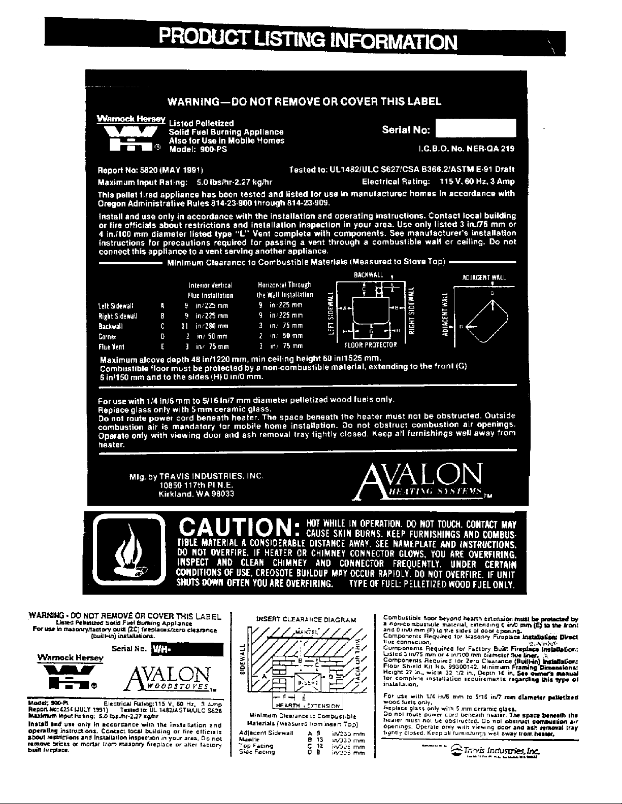
Product Listing Information ------------------------------------------------------------------------------------------------ 44
PAGE 3
Page 4

FEA TURES AND SPECIFICA TIONS
* FREESTANDING
CONVENIENT
LONG BURN TIME
* ALCOVE
VERSATILE
CLOSE CLEARANCES
* MOBILE HOME
DURABLE
* MASONRY FIREPLACE INSERT
* FACTORY-BUILT (Z.C.)
FIREPLACE INSERT
Stove
Heating Capacity SQ/FT ........................ 800 to 2000 Maximum ..................800 to 2000 Maximum
Burn Rate lbs/hr .................................... 1.2 to 4.7 ..................1.2 to 4.7
Emissions Grams/per hour..................... .8 (EPA Exempt) .................. .8 (EPA Exempt)
Maximum Burning Time (Hours) ............ Up to 50 ..................Up to 40
Flue Opening Diameter ..........................3.0" (76 mm) ..................3.0" (76mm)
Height from floor to top of stove on:
Pedestal.............................. 31 3/4" (806 mm) Depth Into Fireplace............ 12 1/4 " (311mm)
Legs, Brass......................... 27 7/8" (708 mm) Extension on to Hearth ....... 12 7/8" (326mm)
Legs, Cast .......................... 27 7/8" (708 mm) Width into Fireplace *.......... See Page 20
Legs, Black .........................26 3/8" (670 mm) Overall Height (Add 1" for flue)....19 " (483mm)
Overall Width..........................................24" (610 mm) .................. 24 1/4" (616 mm)
Overall Depth (Add 2 1/4" for flue) ........25 1/4" (641 mm) .................. 25 3/16 " (640 mm)
Hopper Capacity (lbs) ............................ 60 (27 KG) (Estimated) ..................50 (23 KG) (Estimated)
Unit Weight (lbs).....................................260 (118 KG) ..................240 (109 KG)
Electrical Rating ..................................... 115 Volts, 3 Amps, 60 HZ ..................115 Volts, 3 Amps, 60 HZ
Watts ............................................ 180 (Approx.) ..................180 (Approx.)
POWERFUL EFFICIENT FANS
SUPERIOR AUGER SYSTEM
HUGE HOPPER
STAINLESS STEEL FIREPOT
QUIET OPERATION
Insert
* See Page 20 for exact fireplace sizing
FUEL: The unit is designed to operate using 1/4 inch diameter pellets that comply with A.P.F.I.• standards. If the fuel
does not comply to this standard, the unit may not operate as designed. If the pellets are larger that 1/4 inch diameter
the unit may need adjustments; consult with your dealer.
NOTE: • Store pellets in a clean dry place.
• Emissions information and efficiency information based on tests conducted by E.E.M.C. Laboratory.
BTU. output will vary depending on pellet size, moisture content, burn rate and pellet type. Heating
capacity is subject to variations due to pellet type, relative moisture content, floor plan, degree of home
insulation, and temperature zone.
• A.F.P.I. - Association of Pellet Fuel Industries.
• Heating Capacity is based on maximum burn rate.
• Maximum burn time is based on low burn rate.
PAGE 4
Page 5

PREPARATION FOR INSTALLATION — PELLET STOVE
READ THIS ENTIRE MANUAL BEFORE YOU INSTALL AND USE YOUR NEW APPLIANCE. FAILURE TO
FOLLOW INSTRUCTIONS MAY RESULT IN PROPERTY DAMAGE, BODILY INJURY, OR EVEN DEATH.
PREPARATION:
1. Remove all tape and packaging.
2. Remove the wood shipping frame from around and under the appliance.
3. Check that no parts have become loose and the appliance has not been damaged during shipping.
4. Remove the hardware pack from the appliance.
5. READ THE OWNER'S MANUAL BEFORE PROCEEDING.
* Appliance should be located such that no doors, drapes, furniture or other combustibles can be placed close or
swing closer than the minimum stated clearances.
* The appliance must be installed in a level, secure position.
* Required Floor Protection:
Minimum size 26 1/8"W x 31 1/2"D (664mmW x 800 mmD)
of non-combustible material with a minimum thickness
of 26 gauge (.018", .5mm) floor protection must extend
Chimney Lengths
Vertical
Horizontal
Combined Horizontal &
Vertical
NOTE #1: On chimneys with vertical heights that exceed 15' and/or horizontal runs that exceed 4', a 4" diameter
pellet vent is recommended.
NOTE #2: When this unit is installed above 4000' in altitude, 4" diameter pellet vent should be used.
* Do not obtain combustion air from attic, garage, unventilated crawl space or any other enclosed space. Do not
locate combustion air inlet at an elevation higher than exhaust termination.
* Outside air (combustion air intake) is recommended, but not required, for all residential installations, but is
required for mobile home installations. If an outside air intake (combustion air intake) is used, it must be
connected to a 1-3/4", or larger, metal or aluminium duct with a rodent screen fixed to the termination.
Do not use P.V.C .duct.
NOTE: TRAVIS INDUSTRIES, INC., recommends that an outside air (combustion air) intake be used in all
installations. If one is not used, there is a possibility of combustion gases (smoke) being released into your home,
if there is a power outage while the unit is in operation.
Maximum
33' (10.06 m)
10' (3.05 m)
4' Horizontal 30' Vertical
10' Horizontal 25' Vertical
Front - 6" (152 mm)
Sides - 0" ( 0 mm)
Back - 0" ( 0 mm)
Minimum
Subject to installation. See Fig. 9
Subject to installation. See Fig. 4&9
Any Lesser Combination is
Acceptable.
* The AVALON 900 pellet stove exhaust vent accepts 3" diameter pellet vent pipe. Some of the brands
available for use with the AVALON 900 are:
1. Duravent Model PL-Vent
Simpson Dura-Vent
P.O. Box 1510
Vacaville, CA 95688
(707) 446-1786 or
1-800-227-8846
NOTE: 4" diameter may be substituted when a 3" to 4" adapter is used.
See manufacturer’s installation instructions for precautions required for passing vent through a combustible wall
or ceiling. Do not connect this appliance to a vent serving another appliance.
All sections of pellet vent must be fastened to each other with sheet metal screws and silicone sealed with type
500 degree Fahrenheit (260°C) RTV (high heat) silicone sealer, to ensure that the joints are airtight.
2. James A. Ryder MFG Model PL-Vent
Ryder Mfg., Inc.
241 Arvin Avenue
Stoney Creek, Ontario Canada
(416) 662-1701
PAGE 5
3. MetalFab Model Pellet Vent
P.O. Box 1138
Wichita, KS 67201
(316) 943-2351
Page 6
PREPARATION FOR INSTALLATION Ð
PELLET STOVE (cont.)
Your Pellet Stove appliance comes completely assembled. Options are available for the different types of
installations. The options are listed below and are boxed separately from the appliance. They require assembly.
1. Pedestal.
2. Leg Kit, Black.
3. Leg Kit, Brass.
4. Leg Kit, Cast Black
5. Vertical Pipe Adapter
When lifting the appliance, you may choose to remove the interior components to make it lighter. Refer to the
care & maintenance instructions in this manual for the proper sequence of removal and replacement of internal
components.
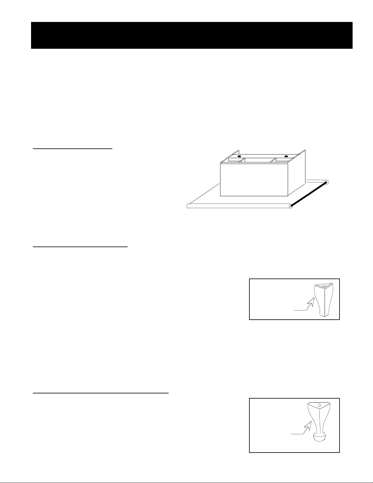
1. Pedestal Assembly:
Open the box marked Pedestal and remove the
pedestal and the two attachment bolts and washers
(3/8" diameter - 16 X 3/4" hex. head bolt).
Lift the stove onto the pedestal. Line up the
threaded bolt holes in the bottom of the stove with
the two holes in the mounting angle of the pedestal
(some models use clips that attach to the side of
the pedestal -- the same directions apply).
Using a 9/16" open-end or socket wrench, fasten the pedestal to the stove with the supplied bolts and washers.
NOTE: Keep the two front leg bolts in place when installing on a pedestal -- otherwise air will enter through these
holes.
2. Leg Kit, Black Assembly:
Open the box marked Leg Kit, Black and remove the four 6-1/2" high black steel legs, complete with rubbertipped leveling bolts (on certain models they are not rubber tipped Ð the same directions apply), the four
attachment bolts (3/8" diameter - 16 X 3/4" hex. head bolt) and the washers.
Raise the stove on some pieces of lumber to a height of about 7". Make sure
to level the stove at this point using shims under the pieces of lumber. Line up
the hole in the top of the leg with the threaded bolt hole in each corner of the
stove bottom. Using a 9/16" open end or socket wrench, fasten the leg to the
stove with the supplied attachment bolts and washers, making sure the legs are
flush with the corners of the stove.
To level the stove, first make sure the leveling bolts with the rubber ends (some models come with steel bolts -the same directions apply) are screwed into position and backed off just enough to penetrate below the steel
portion of the leg. Unscrew each leveling bolts just enough so each leveling bolt is an equal distance from the
floor. You may wish to use a piece of wood or other spacer to measure this distance. As long as the lumber
holding the stove in place is properly leveled, the stove will be level when the leveling bolts are adjusted properly
and the lumber is removed. Next, lower the stove onto the ground and check for a level position. If slight
adjustments need to be made, make sure to first raise the stove before turning the leveling bolts. The rubber tips
of the leveling bolts will tear if they are adjusted while weight is applied to them.
3. & 4. Leg Kit, Brass or Cast Black Assembly:
Open the box marked Leg Kit, Brass (or Cast) and remove the four 7-7/8"
high legs, complete with rubber-tipped leveling bolts(on certain models they are
not rubber tipped Ð the same directions apply), the four attachment bolts (3/8"
diameter - 16 X 3/4" hex. head bolt) and the washers.
Use the same directions listed above for the Leg Kit, Black assembly. The one
difference is that the Brass (or Cast) legs are taller, and the stove should be
lifted approximately 8 1/2" above the floor before attachment.
PAGE 6
Attach Bolt (with
washer) to Stove
From Below
Attach Bolt (with
washer) to Stove
From Below
Page 7
PREPARATION FOR INSTALLATION Ð
PELLET STOVE (cont.)
5. Vertical Pipe Adapter:
The vertical pipe adapter is an optional item used to center the pellet vent on the pellet stove. It allows for a more
compact installation then using offsets on the pellet vent. To install the vertical pipe adapter, follow the directions
below.
1. Take the vertical pipe adapter, along with the 5 screws, out of the box and inspect for any damage.
2. When determining the final position of the stove, take into consideration the location of the vertical pipe
adapter once it is installed. It is best to install the vertical pipe adapter before determining the location of
the stove, making the final alignment with the pellet vent more accurate.
3. The vertical pipe adapter allows for the use of 3" pellet vent or 6" singlewall or doublewall stovepipe. Use
the appropriate collar for the vent type used.
4. Insert the vertical pipe adapter onto the pellet stove and align it so the length of the adapter is vertical. On
the the vertical pipe adapter where it connects to the exhaust pipe there are three holes. One is on the
outward side, one is on the top, and one is located on the bottom. Make a mark on the exhaust tube
where these holes line up. Make sure the pipe adapter is all the way against the exhaust pipe and
properly aligned when making these marks. Take the vertical pipe adapter off and drill a 9/64" hole where
the three marks where placed on the exhaust pipe.
5. Apply a high-temperature silicone sealant (type 500 degree RTV) around the outside perimeter of the
exhaust pipe near the end and slide the vertical pipe adapter into place. Attach the vertical pipe adapter
to the exhaust pipe by sliding it into place and screwing in the three sheet-metal screws through the
vertical pipe adapter and into the holes that were drilled in step 4. Inspect the connection between the
exhaust pipe and vertical pipe adater for an airtight seal. Apply more high-temperature silicone sealant if
necessary.
6. The vertical pipe adapter has a sheet metal bracket used to secure the vertical pipe adapter to the stove.
It attaches to the back of the stove in two locations. Drill the 9/64" holes in the back of the stove. Drill
only enough to penetrate the first layer of metal. Screw in the remaining two sheet-metal screws with a
phillips-head screwdriver.
7. The vertical pipe adapter can now be attached to the vent. Make sure to seal the connection between the
vertical pipe adapter and vent with a high-temperature silicone sealant (type 500 degree RTV).
Drill Three Holes for the
Screws that hold the
Vertical Pipe Adapter
to the Exhaust Pipe
Collar for 3"
Pellet vent
Collar for 6"
Stovepipe
Sheet Metal Bracket Used
to Secure the Vertical Pipe
Adapter to the Stove
Remove this Plate to Clean the Vertical Pipe Adapter
Use the Three Holes on the Verttical Pipe Adapter to mark the
Three Holes that will be drilled into the Exhaust Pipe (Make sure
the Vertical Pipe Adapter is Vertical and fully inserted)
PAGE 7
Page 8
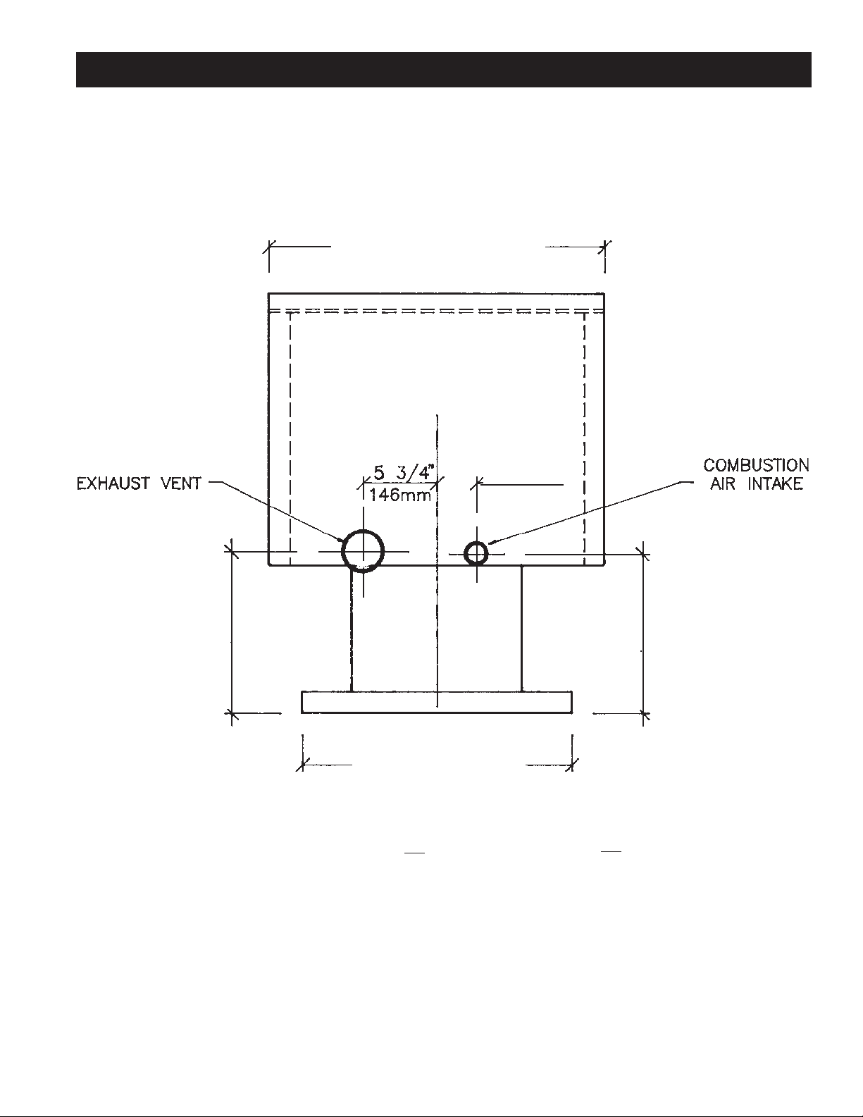
FREESTANDING INSTALLATION - SPECIFICATIONS
24 1/4" [616 mm]
3 3/16"
83 mm
Accepts 3" DIA
Pellet Vent
1 3/4" O.D.
(44mm)
"A"
23 " Min. [603]
“A”
PEDESTAL 13 3/4" (348mm) 14 7/8" (387mm)
LEGS, BRASS 9 3/4" (248mm) 10 7/8" (276mm)
LEGS, CAST 9 3/4" (248mm) 10 7/8" (276mm)
LEGS, BLACK 8 3/8" (213mm) 9 1/2" (241mm)
FIGURE 1
“B”
"B"
PAGE 8
Page 9
FREESTANDING INSTALLATION SPECIFICATIONS (cont.)
FLOOR PROTECTION: (Fig. 2 & 3)
G. Front 6" (152 mm) NOTE: Front floor protection is measured from the door opening.
H. Sides 0" (0mm)
H. Back 0" (0mm)
NOTE: Floor protector should extend to areas below and 2" (50 mm) to each side of a "tee" when used (See Fig. 6).
CLEARANCE TO COMBUSTIBLES:
INTERIOR VERTICAL FLUE INSTALLATION
Figures 2 & 3
A Sidewall to unit 9" - (229 mm)
B Backwall to unit 11" - (279 mm)
C Corner wall to unit 2" - ( 51 mm)
D Flue vent/chimney 3" - ( 76 mm)
NOTE: Dimension "C" , corner to unit, and "B", backwall to unit, will vary depending on the type and brand of
pellet vent or interior connector used. Always maintain the "D" dimension, pellet vent/interior connector
clearance, when installing this unit. Check your pellet vent/interior connector instructions for information on its
size and clearance required to comustibles. NOTE: Singlewall interior connectors require a minimum 3"
clearance to combustibles.
HORIZONTAL THROUGH THE WALL INSTALLATION OR VERTICAL
EXTERIOR INSTALLATION
Figures 2 & 3
A Sidewall to unit 9" - (229 mm)
B Backwall to unit 3" - ( 76 mm)
C Corner Wall to unit 2" - ( 51 mm)
D Flue vent/chimney 3" - ( 76 mm)
VERTICAL
PIPE
ADAPTER
3" Pellet Vent 6" Stovepipe
9" - (229 mm) 9" - (229 mm)
7" - (178 mm) 9" - (229 mm)
2" - ( 51 mm) 2" - ( 51 mm)
3" - ( 76 mm) 3" - ( 76 mm)
SIDEWALL
BACKWALL
B
A
D
G
H
H (0")
FIGURES 2 & 3
PAGE 9
CORNER WALL
CORNER WALL
C
H
H (0")
C
G
Page 10
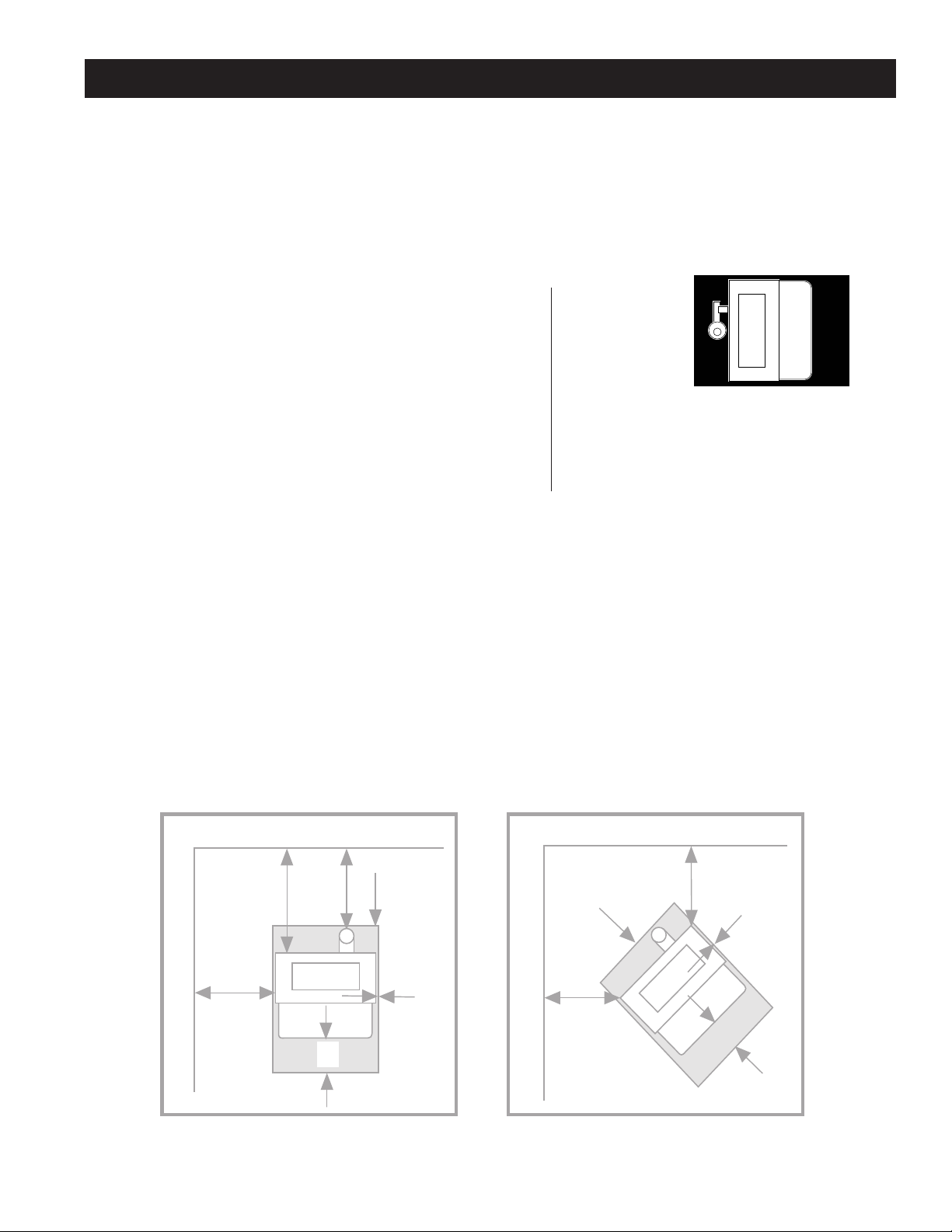
HORIZONTAL CORNER INSTALLATION
OPTIONAL AIR INTAKE
PELLET VENT
CHIMNEY CAP
FIGURE 4
The exhaust vent termination on either vertical or horizontal installations shall be located as follows:
• A minimum of 4 feet (1219 mm) below or beside and a minimum of 1 foot (305 mm) above any door
or window that opens, or any opening into a building.
• A minimum of 2 feet (610 mm) from any adjacent building.
• A minimum of 7 feet (2134 mm) above grade, when located adjacent to public walkways.
• A minimum of 2 feet (610 mm) above grass, plants or other combustible surfaces.
PAGE 10
Page 11
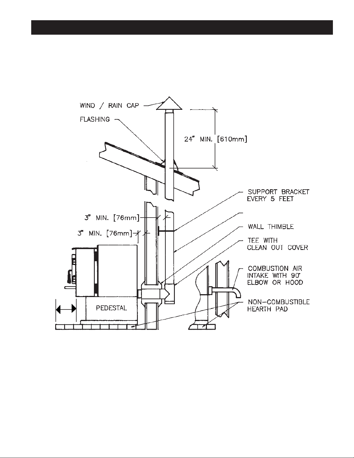
VERTICAL EXTERIOR FLUE SYSTEM
NOTE: FOR STANDARD OR CORNER INSTALLATION, STANDARD INSTALLATION SHOWN.
PELLET VENT
OPTIONAL
6" MIN.
(152mm)
▲
▲
FIGURE 5
The exhaust vent termination on either vertical or horizontal installations shall be located as follows:
• A minimum of 4 feet (1219 mm) below or beside and a minimum of 1 foot (305 mm) above any door
or window that opens, or any opening into a building.
• A minimum of 2 feet (610 mm) from any adjacent building.
• A minimum of 7 feet (2134 mm) above grade, when located adjacent to public walkways.
• A minimum of 2 feet (610 mm) above grass, plants or other combustible surfaces.
PAGE 11
Page 12
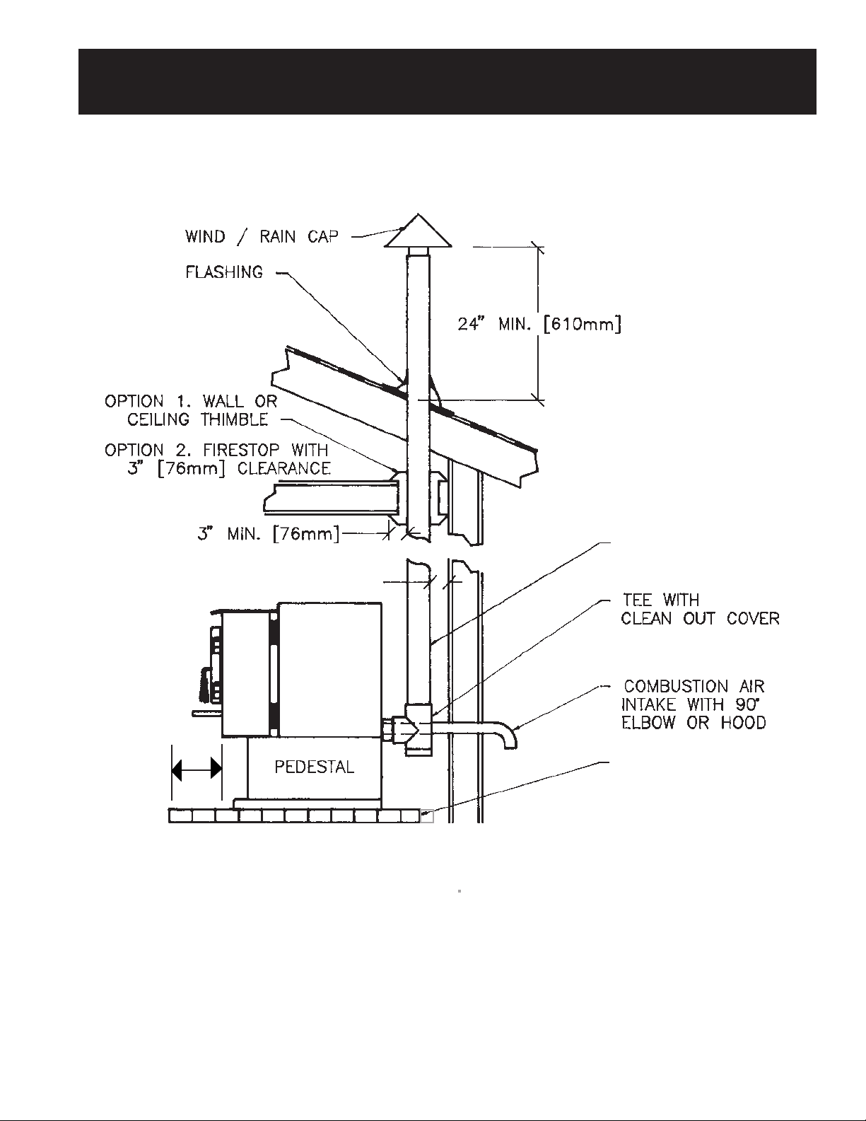
INSIDE VERTICAL INSTALLATION
WITH ROOF TERMINATION
NOTE: FOR STANDARD OR CORNER INSTALLATION, STANDARD INSTALLATION SHOWN.
PELLET VENT
3" MIN. (76MM)
OPTIONAL
6" MIN.
(152mm)
The exhaust vent termination on either vertical or horizontal installations shall be located as follows:
▲
▲
FIGURE 6
NON-COMBUSTIBLE
MATERIAL TO
EXTEND UNDER TEE
• A minimum of 4 feet (1219 mm) below or beside and a minimum of 1 foot (305 mm) above any door
or window that opens, or any opening into a building.
• A minimum of 2 feet (610 mm) from any adjacent building.
• A minimum of 7 feet (2134 mm) above grade, when located adjacent to public walkways.
• A minimum of 2 feet (610 mm) above grass, plants or other combustible surfaces.
PAGE 12
Page 13
HEARTH STOVE INSTALLATION INTO EXISTING
MASONRY & ZERO CLEARANCE (METAL) FIREPLACE
SEAL COVER PLATE TO
CHIMNEY WITH SILICONE
SEALER.
POSITIVE CONNECTION
(COMPLETE RELINE)
3" STAINLESS STEEL SINGLE
☛
WALL PIPE OR FLEXIBLE
LINER CAN BE USED.
(SEE NOTE BELOW).
SINGLE WALL TEE CAN BE
USED AS AN OPTION.
BLOCK-OFF PLATE OR
☛
NON-COMBUSTIBLE
MATERIAL MAY BE USED
AT THE FIREPLACE
DAMPER LOCATION. THIS
SEAL MUST BE AIRTIGHT.
(SEE BELOW)
▼
TERMINATION OF
12"
DIRECT CONNECTION.
▼
OPTIONAL
6" MIN.
(152mm)
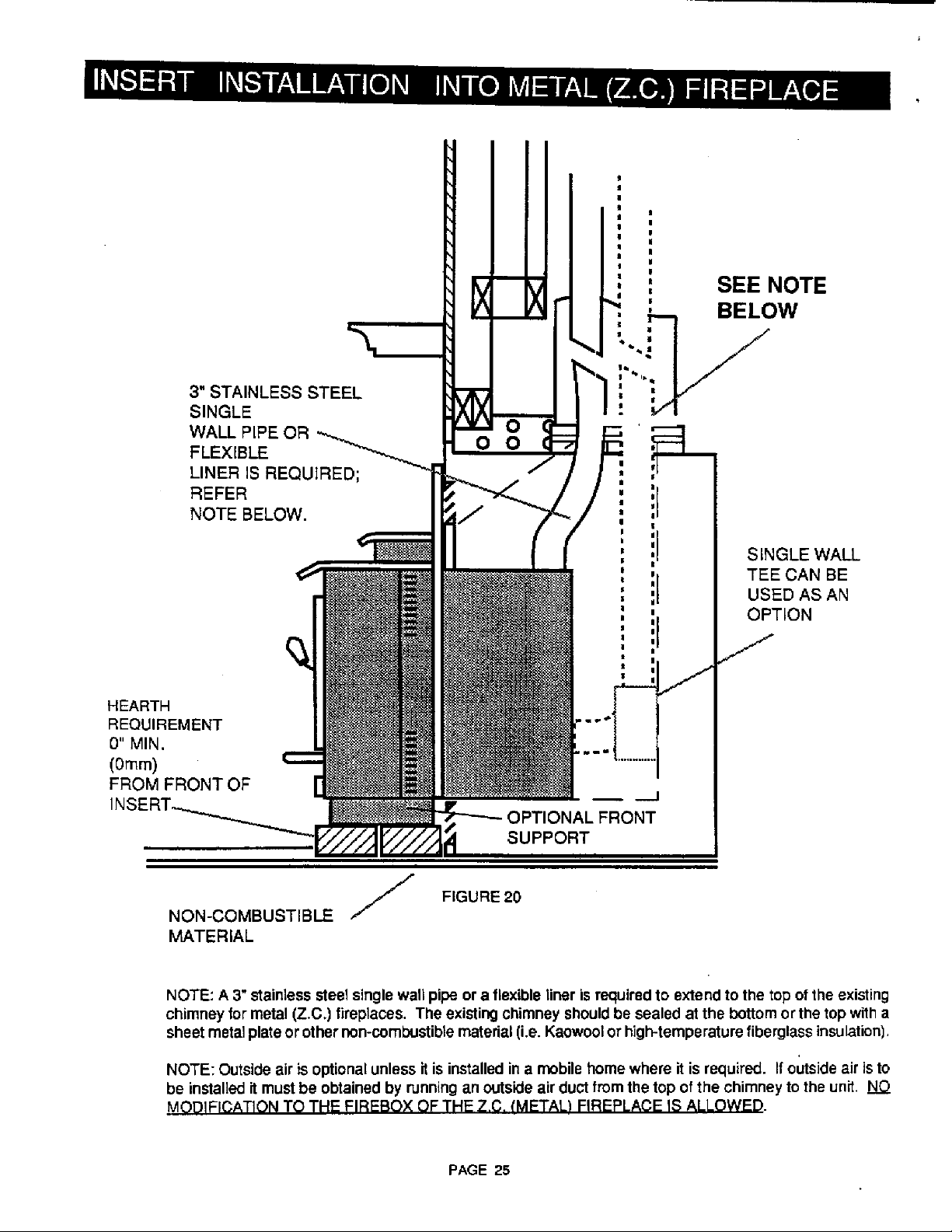
NOTE: Masonry fireplace installations require a direct connection or positive (complete reline) connection to the
chimney flue. With a direct connection a block-off plate made of metal or other non-combustible material
(i.e. Kaowool or high temperature fiberglass insulation) must be used at the damper location and sealed
airtight. The singlewall pipe or flexible liner must extend past the block-off plate or insulation by one (1) foot
(305 mm) or to the first flue tile if the chimney has a tile lining.
With a positive connection, the block-off plate at the damper location is optional, but a sealed cover plate
is required at the top of the chimney. A positive connection (complete reline) is recommended for ease of
cleaning. Zero clearance (metal) fireplace installations require a complete reline to top of chimney.
▲
▲
FIGURE 7
PAGE 13
Page 14
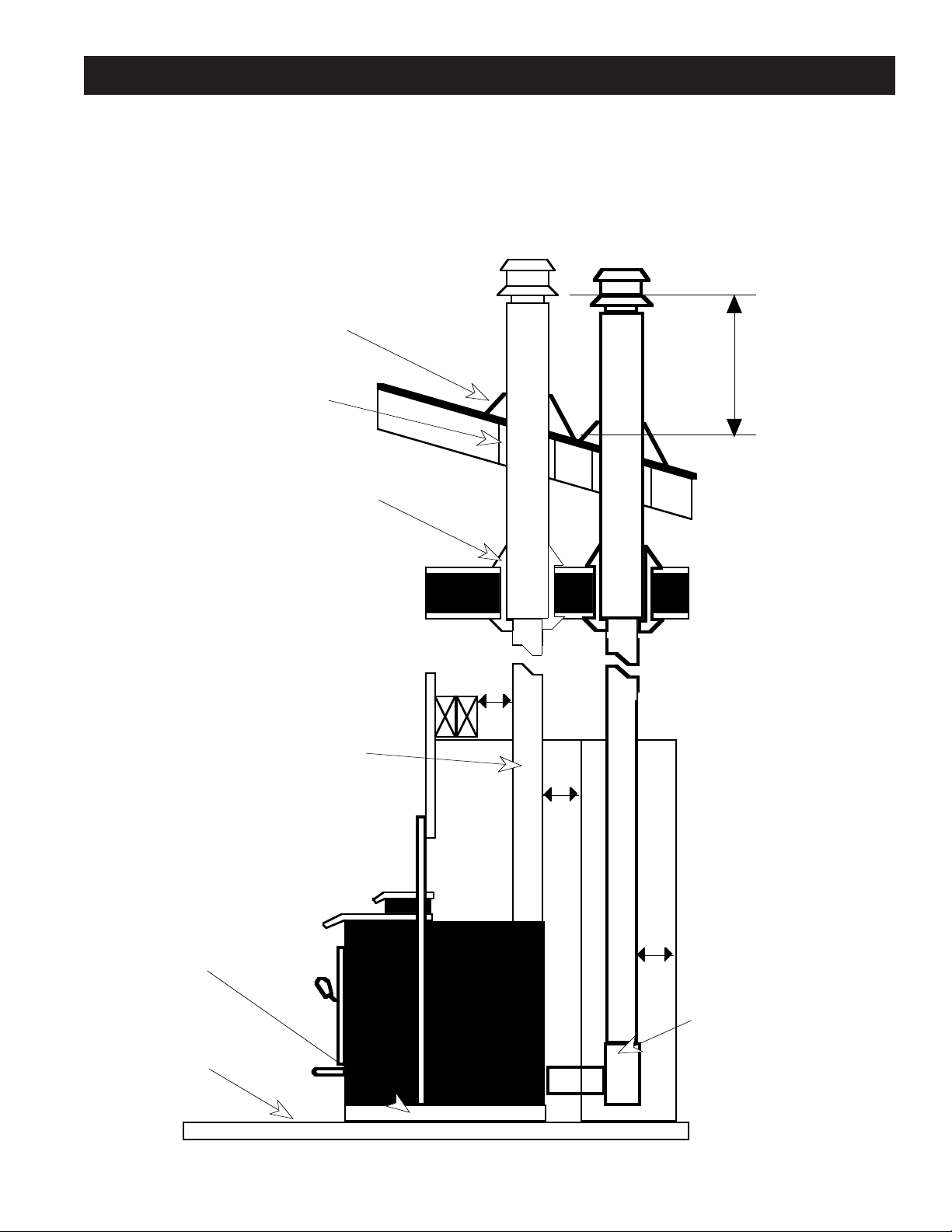
VERTICAL INSTALLATION INTO EXISTING
FACTORY BUILT CHIMNEY
NOTE: FOR STANDARD OR CORNER INSTALLATION, STANDARD INSTALLATION SHOWN.
Flashing
24" Min. (610mm)
OPTION 1. Wall Or
Ceiling Thimble
OPTION 2. Firestop With
3" (76mm) Clearance
Keep Clearance Specified
By Factory Built Chimney
Manufacturer
6" Min.
(152mm)
3" Min. (76mm)
Pellet Vent To Factory
Built Adaptor Required
Pellet Vent
Tee With
Clean Out Cover
Optional
Combustion Air
Intake With 90˚
Elbow Or Hood
Non-Combustible
Material To Extend
Under The Tee
FIGURE 8
The exhaust vent termination on either vertical or horizontal installations shall be located as follows:
• A minimum of 4 feet (1219 mm) below or beside and a minimum of 1 foot (305 mm) above any door
or window that opens, or any opening into a building.
• A minimum of 2 feet (610 mm) from any adjacent building.
• A minimum of 7 feet (2134 mm) above grade, when located adjacent to public walkways.
• A minimum of 2 feet (610 mm) above grass, plants or other combustible surfaces.
PAGE 14
Page 15

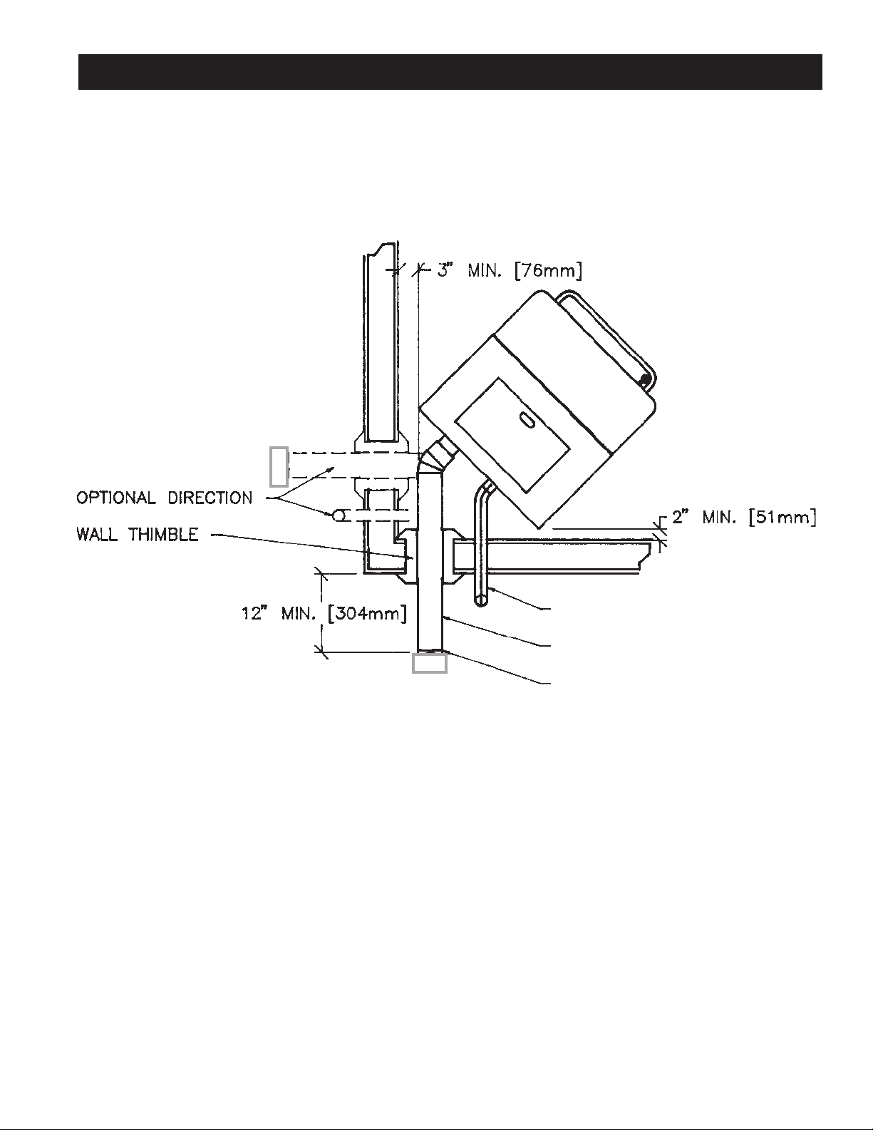
HORIZONTAL INSTALLATION
24"
▼
24" (610mm)
▼
REFER NOTE
▼
▼
12" MIN
CHIMNEY CAP
305mm
6" MIN.
(152mm)
▲
▲
OPTIONAL
MATERIAL
FIGURE 9
NOTE: A 6 ft. (1829mm) vertical rise is recommended to maintain a better draft. However, a shorter rise may
be used. Vertical installation as in Figure 5 is preferred. If a shorter rise is used and the termination is under
an eave or overhang, the termination must be at least 24" (610mm) from the combustible material, and the
chimney must be vented at least 12" (305mm) from the dwelling.
The exhaust vent termination on either vertical or horizontal installations shall be located as follows:
• A minimum of 4 feet (1219 mm) below or beside and a minimum of 1 foot (305 mm) above any door
or window that opens, or any opening into a building.
• A minimum of 2 feet (610 mm) from any adjacent building.
• A minimum of 7 feet (2134 mm) above grade, when located adjacent to public walkways.
• A minimum of 2 feet (610 mm) above grass, plants or other combustible surfaces.
PAGE 15
Page 16

Page 17

RESIDENTIAL ALCOVE INSTALLATION
9" MIN.
(229mm)
9" MIN.
(229mm)
42 1/4" (1074mm)
44 1/8"
FIGURE 11
MINIMUM ALCOVE HEIGHT 60" - (1524mm)
MAXIMUM ALCOVE DEPTH 48" - (1219mm)
PAGE 17
1121
Page 18

PREPARATION FOR INSTALLATION — PELLET INSERT
READ THIS ENTIRE MANUAL BEFORE YOU INSTALL AND USE YOUR NEW APPLIANCE. FAILURE TO
FOLLOW INSTRUCTIONS MAY RESULT IN PROPERTY DAMAGE, BODILY INJURY, OR EVEN DEATH.
PREPARATION:
1. Remove all tape and packaging.
2. Remove the wood shipping frame from around and under the appliance.
3. Check that no parts have become loose and the appliance has not been damaged during shipping.
4. Remove the hardware pack from the appliance.
5. READ THE OWNER'S MANUAL BEFORE PROCEEDING.
* Appliance should be located such that no doors, drapes, furniture or other combustibles can be placed close or
swing closer than the minimum stated clearances.
* The appliance must be installed in a level, secure position.
* Required Floor Protection: (Fig. 10)
NOTE: Minimum hearth extension 24" W (610 mm) x 16" D (406 mm) from fireplace opening.
Chimney Lengths
Vertical
Horizontal
Combined Horizontal &
Vertical
NOTE #1: On chimneys with vertical heights that exceed 15' and/or horizontal runs that exceed 4', a 4" diameter
pellet vent is recommended.
NOTE #2: When this unit is installed above 4000' in altitude, 4" diameter pellet vent should be used.
* Do not obtain combustion air from attic, garage, unventilated crawl space or any other enclosed space. Do not
locate combustion air inlet at an elevation higher than exhaust termination.
* Outside air (combustion air intake) is recommended, but not required, for all residential installations, but is
required for mobile home installations. If an outside air intake (combustion air intake) is used, it must be
connected to a 1-3/4", or larger, metal or aluminum duct with a rodent screen fixed to the termination.
Do not use P.V.C .duct.
NOTE: TRAVIS INDUSTRIES, INC., recommends that an outside air (combustion air) intake be used in all
installations. If one is not used, there is a possibility of combustion gases (smoke) being released into your home,
if there is a power outage while the unit is in operation.
* The AVALON 900 pellet insert exhaust vent accepts 3" diameter pellet vent pipe. Some of the brands
available for use with the AVALON 900 are:
Maximum
33' (10.06 m)
10' (3.05 m)
4' Horizontal 30' Vertical
10' Horizontal 25' Vertical
Minimum
Subject to installation. See Fig. 9
Subject to installation. See Fig. 4&9
Any Lesser Combination is
Acceptable.
1. Duravent Model PL-Vent
Simpson Dura-Vent
P.O. Box 1510
Vacaville, CA 95688
(707) 446-1786 or
1-800-227-8846
NOTE: 4" diameter may be substituted when a 3" to 4" adapter is used.
See manufacturer’s installation instructions for precautions required for passing vent through a combustible wall
or ceiling. Do not connect this appliance to a vent serving another appliance.
All sections of pellet vent must be fastened to each other with sheet metal screws and silicone sealed with type
500 degree Fahrenheit (260°C) RTV (high heat) silicone sealer, to ensure that the joints are airtight.
2. James A. Ryder MFG Model PL-Vent
Ryder Mfg., Inc.
241 Arvin Avenue
Stoney Creek, Ontario Canada
(416) 662-1701
PAGE 18
3. MetalFab Model Pellet Vent
P.O. Box 1138
Wichita, KS 67201
(316) 943-2351
Page 19
PREPARATION FOR INSTALLATION —
NOTE
TABS
UNLATCH
SECOND
REMOVE
GASKET
PELLET INSERT (cont.)
NOTE: The fireplace cavity must be thoroughly cleaned prior to installation. It should be cleaned with a wire brush or
scraper and then painted with a latex paint to eliminate the possibility of odors from the fireplace being circulated into
the house by the room air fan of the pellet insert.
For your safety, examine the fireplace and chimney prior to installation of the pellet insert to determine that they are
free from cracks, loose mortar, creosote deposits, blockages, or other signs of deterioration. If evidence of
deterioration is noted, the pellet insert should not be installed until after repairs have been made. Any opening
between the masonry of the fireplace and the facing masonry must be permanently sealed.
Your pellet insert is listed for installation into masonry fireplaces, and is approved to be installed with or without
positive or direct chimney connection.
Your pellet insert is also approved for installation into metal or zero-clearance (Z.C.) fireplaces. Metal or Z.C.
installation requires a full reline with a 3" stainless steel single-wall pipe or a flexible liner.
Your Avalon 900 Pellet Insert appliance comes completely assembled, with the exception of the switch box, panels
and panel trim. Options available for the different types of installations are:
1. Adjustable Front Insert Support.
2. Panels - 8", 10", or 12"
3. Ceramic Log
The above items come boxed separately and require assembly.
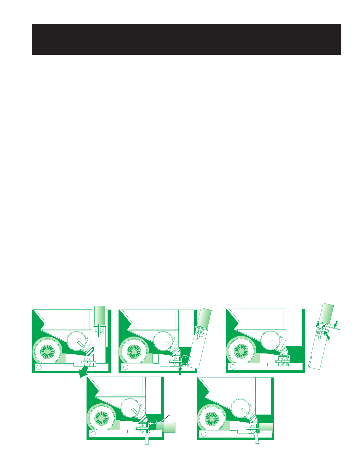
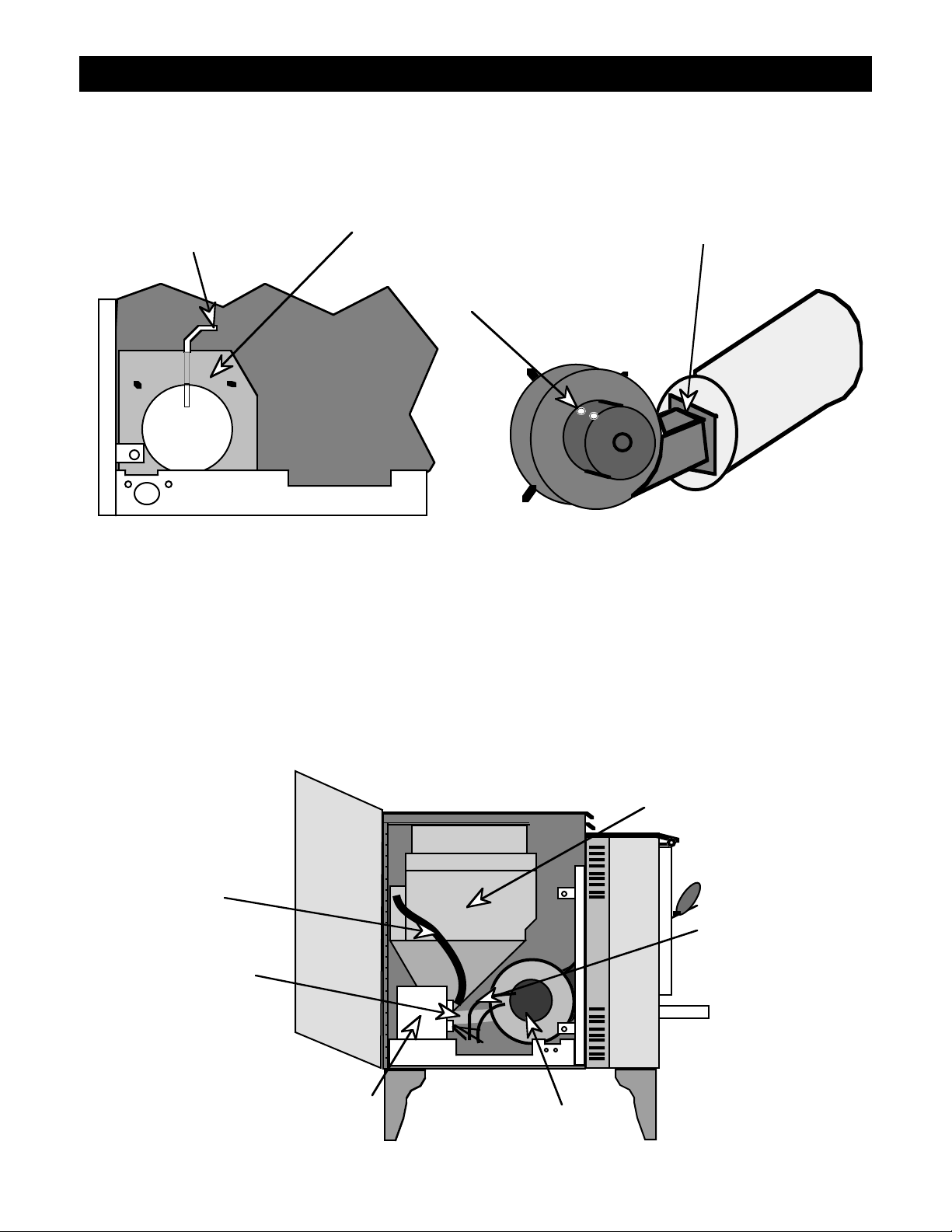
VENT CONFIGURATION:
The 900 Pellet Insert is equipped with a dual vent configuration. It can be vented vertically or horizontally. Before
installing, you must determine which configuration will best suit your installation.
The unit comes set up for a vertical installation (Fig. 12-A). To change it to a horizontal venting configuration,
remove the 1/4" hex head bolt and clamp holding the vertical vent to the base of the unit, next release the spring clip
on the side of the lower vent duct , (Fig. 12-B) and remove the vent assembly then release the spring clip holding the
round portion of the vent to the rectangular portion (Fig. 12-C). To complete the change over, clip the round portion
into the lower vent duct bracket (Figs. 12 D & E).
NOTE: Make sure that the gaskets are not damaged and are in the proper position before latching the spring clip.
FIG. 12-A
UNLATCH FIRST
FIG. 12-D
FIG. 12-B
NOTE
TABS
LEAVE GASKETING
IN PLACE
TAKE OFF
VERTICAL FLUE
ATTACHMENT
FIG. 12-E
FIG. 12-C
MAKE SURE
GASKETING
IS IN PLACE
NOTE
TABS
NOTE
TABS
PAGE 19
RELATCH
Page 20
Page 21

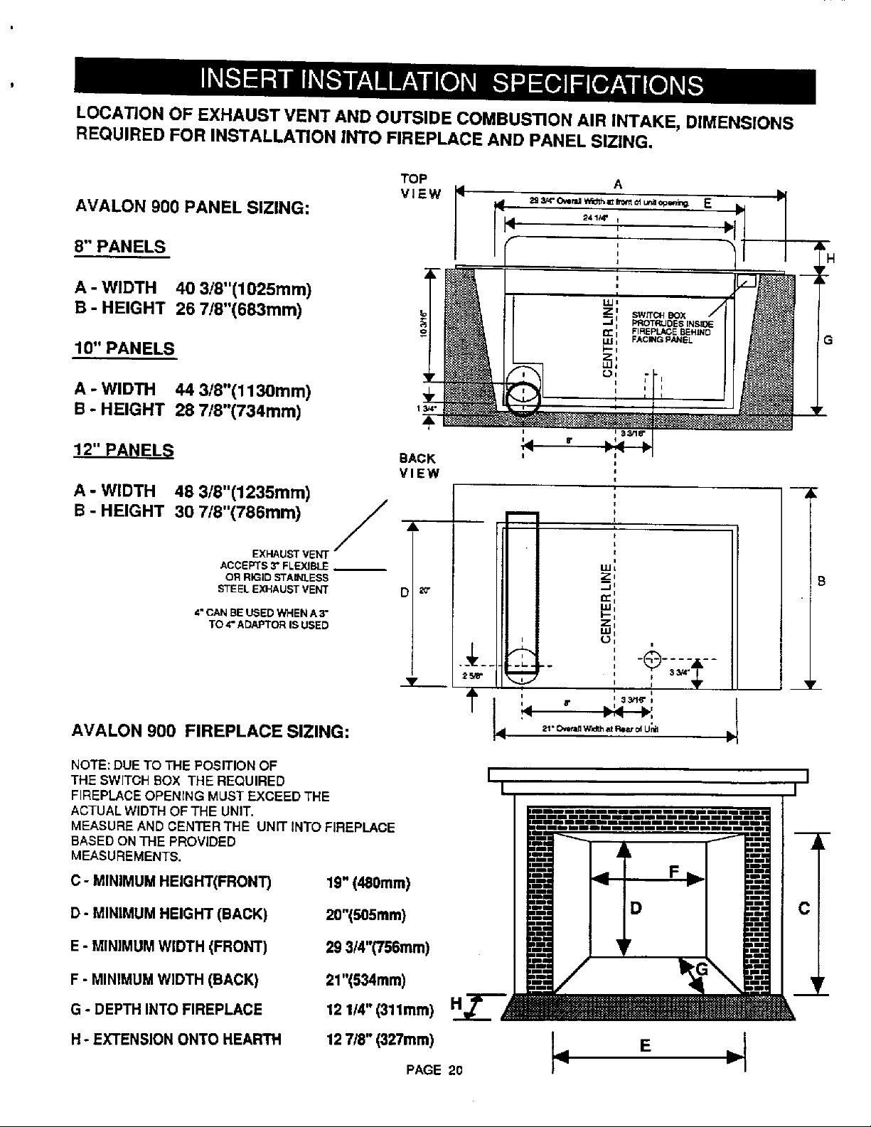
INSERT INSTALLATION SPECIFICATIONS (Cont.)
FLOOR PROTECTION: (Fig.10 )
E. Front 0" (0mm)
F. Sides 0" (0mm)
NOTE: Although a non-combustible hearth extension is not required to extend past the front and sides of
the insert, the insert must be installed on a non-combustible hearth that extends to the front and side
edges of the insert.
CLEARANCE TO COMBUSTIBLES: (Fig. 10)
A. Adjacent Sidewall 9" (229mm)
B. Side Facing 8" (203mm)
C. Top Facing 12" (305mm)
D. Mantle 13" (330mm)
NOTE: For clearances, use this clearance diagram (fig. 10 ) or the clearance diagram on the
safety label attached to the back of the appliance.
MANTLE
D
GH
SIDEWALL
DIRECT CONNECTION:
1. Make sure the fireplace and chimney are thoroughly cleaned, inspected and repaired where necessary to
make it safe. Paint with a latex paint as explained on Pg. 19.
A
I
F
0"
Figure 10
E
C
0"
B
J
2. Wire open or remove the firebox damper.
3. Measure the area of the firebox below the damper opening and above the lintel. Transfer these
measurements to a piece of galvanized sheet metal (min. 24 gauge) and add 2" to each side. Mark the
position of several holes on each side, to suit your specific installation, and drill 1/4" diameter holes. Next
bend the 2" extended side to a 45° angle. The 2" lip with the 1/4" diameter holes will allow you to screw
the plate to the firebox walls.
PAGE 21
Page 22

INSERT INSTALLATION SPECIFICATIONS - (cont.)
DIRECT CONNECTION: (Continued)
4. A hole must be cut in the plate to allow the chimney connector to pass through from the appliance into the
chimney. Mark the hole position on the plate so that the center of the hole is in line with the center line of the
appliance flue. A flexible stainless steel connector works best if an offset is required.
5. Position the plate in the firebox where the measurements were taken. Secure the plate with screws through
the holes in the lip, and seal around the outside edges of the plate with fiberglass insulation, furnace cement,
or both.
6. Insert the chimney connector (flexible or rigid single-wall stainless steel, 3" diameter and at least 24" long) up
through the hole in the plate and damper opening into the chimney. Seal where vent passes through blockoff plate. This should be done on completion of connection.
NOTE: Masonry fireplace installations require a direct connection or positive (complete reline) connection to
the chimney flue. With a direct connection a block-off plate made of metal or other non-combustible material
(i.e. Kaowool or high temperature fiberglass insulation) must be used at the damper location and sealed
airtight. The singlewall pipe or flexible liner must extend past the block-off plate or insulation by one (1) foot
(305 mm) or to the first flue tile if the chimney has a tile lining.
With a positive connection, the block-off plate at the damper location is optional, but a sealed cover plate is
required at the top of the chimney. A positive connection (complete reline) is recommended for ease of
cleaning.
PANEL INSTALLATION:
7. Lay a protective covering such as a towel or blanket on the floor to protect the floor and the panel finish. Remove,
from the box marked Panels, one top panel and two side panels. Make sure that the panels are large enough to
cover the fireplace opening. NOTE: Route the power cord out of the fireplace so it exits through the lower outside
front corner of the fireplace opening. DO NOT ROUTE THE POWER CORD UNDER THE UNIT.
8. Align the side panels with the sides of the unit. The panels are notched and simply clip onto the sides of the unit.
9. Unwrap the Switch Box (shipped inside the firebox of the appliance) and clip it into the panel. The Power Switch
should be at the top and the Blower Control at the bottom. This must be done prior to the installation of the top
panel.
10. Position the top panel over the unit. Align the clips and slide the top panel over the side panel flanges and the top
of the unit. Press down firmly to make a secure fit.
11. Place the trim face down on the floor, as it would appear on the unit. Place the corner brackets in the appropriate
slots, insert the set screws and tighten firmly.
12. Slide the completed trim assembly over the panels.
You may wish to use two-sided tape at the ends of the
trim to hold it firmly against the bottom of the side
panels.
13. Push the assembled insert, panels and trim into the
fireplace until the spacers make contact with the face of
the fireplace. Be careful not to scratch the hearth.
NOTE: Maintain at least a 3/8" air gap around the
outside edge of the panels. This allows air to flow
around the unit. If this gap is not maintained, the unit
could overheat.
14. Make sure that the insert is square in the fireplace
opening.
PAGE 22
Switch Box
Attaches to
Side Panel Here
Page 23

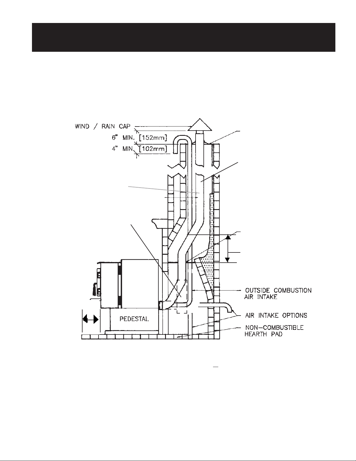
INSERT INSTALLATION INTO EXISTING
MASONRY FIREPLACE
WIND / RAIN CAP
6" MIN. (152mm)
4" MIN. (102mm)
3" STAINLESS STEEL
☛
SINGLE
WALL PIPE OR
FLEXIBLE
LINER IS REQUIRED;
REFER
NOTE BELOW.
▼
▼
▼
▼
OUTSIDE COMBUSTION
AIR INTAKE
POSITIVE CONNECTION
(FULL RELINE)
SEE NOTE
BELOW
12" DIRECT CONNECTION
TERMINATION
SINGLE WALL TEE
CAN BE USED AS AN
OPTION
HEARTH
REQUIREMENT
0" MIN.
(0mm)
FROM
FRONT
OF INSERT
NON-COMBUSTIBLE
MATERIAL
NOTE: Masonry fireplace installations require a direct connection or positive (complete reline) connection to the chimney
flue. With a direct connection a block-off plate made of metal or other non-combustible material (i.e. Kaowool or
high temperature fiberglass insulation) must be used at the damper location and sealed airtight. The singlewall
pipe or flexible liner must extend past the block-off plate or insulation by one (1) foot (305 mm) or to the first flue
tile if the chimney has a tile lining.
FIGURE 24
AIR INTAKE OPTIONS
OPTIONAL
OUTSIDE
AIR INTAKE
With a positive connection, the block-off plate at the damper location is optional, but a sealed cover plate is
required at the top of the chimney. A positive connection (complete reline) is recommended for ease of cleaning.
PAGE 23
Page 24

INSERT INSTALLATION INTO EXISTING
3" STAINLESS STEEL
SINGLE
WALL PIPE OR
FLEXIBLE
LINER IS REQUIRED;
REFER
NOTE BELOW.
MASONRY FIREPLACE (cont.)
SEE NOTE
BELOW
12" DIRECT CONNECTION
TERMINATION
SINGLE WALL TEE
CAN BE USED AS AN
OPTION
HEARTH
REQUIREMENT
0" MIN.
(0mm)
FROM
FRONT
OF UNIT
NON-COMBUSTIBLE
MATERIAL
NOTE: Masonry fireplace installations require a direct connection or positive (complete reline) connection to the chimney
flue. With a direct connection a block-off plate made of metal or other non-combustible material (i.e. Kaowool or
high temperature fiberglass insulation) must be used at the damper location and sealed airtight. The singlewall
pipe or flexible liner must extend past the block-off plate or insulation by one (1) foot (305 mm) or to the first flue
tile if the chimney has a tile lining.
With a positive connection, the block-off plate at the damper location is optional, but a sealed cover plate is
required at the top of the chimney. A positive connection (complete reline) is recommended for ease of cleaning.
FIGURE 25
PAGE 24
AIR INTAKE OPTIONS
OPTIONAL OUTSIDE
COMBUSTION AIR INTAKE
OUTSIDE COMBUSTION
AIR INTAKE
OPTIONAL
OUTSIDE
AIR INTAKE
Page 25
Page 26

INSERT INSTALLATION - ZERO CLEARANCE (BUILT-IN)
The minimum combustible framing dimensions using 3" diameter type "L" listed pellet vent is listed below:
A = Height of 27"
A
B = Depth of 16"
C = Width of 32 1/2"
B
C
This type of installation requires the use of the floor shield kit. The floor shield is boxed separately and can be installed
by following the directions below:
1. Take the floor shield out of the box and make sure the insulation is still placed on the floor shield. The box contains
the floor shield, the bottom panel extension, 8 self-tapping screws, and 2 front leveling bolts.
2. Prop up the front of the insert approximately one foot so that it rests on its rear edge. Remove the front leveling
bolts already attached to the insert and discard. Remove the rear leveling bolts (if attached). Attach the floor shield
to the bottom of the insert by screwing in the eight screws with a phillip-head screwdriver. Attach the two front
leveling bolts included with the floor shield to the floor shield. Then re-attach the two rear leveling bolts through
the floor shield and into the insert.
3. Return the stove to the upright position.
4. The insert can then be placed in the zero clearance cavity and leveled. To level, first measure the step-down
before placing the insert into the cavity. Adjust the front and rear leveling bolts to accomodate any difference. Final
leveling can be done by lifting the insert and turning the leveling bolts to accomodate the level installation. The
magnetized bottom panel extension comes with the floor shield and can be attached by placing it against the insert
panels.
INSERT
Insulation
Front Leveling
Bolts (2)
Holes for back Leveling Bolts
PAGE 26
Page 27
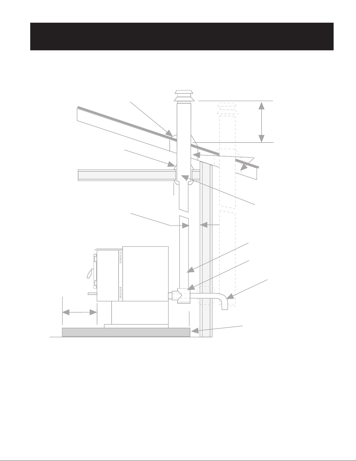
INSERT INSTALLATION - ZERO CLEARANCE (BUILT-IN)
(CONTINUED)
The pellet vent must maintain a 3" clearance from any combustible. Make sure to follow the clearance specified by the
manufacturer for the factory built chimney when making the opening in the roof. Whenever a ceiling or floor is penetrated
an approved thimble or firestop with 3" clearance must be used. See the illustration below for other specifications that must
be met.
Flashing
24" Min.
Keep Clearance Specified
By Factory Built Chimney
Manufacturer
OPTION 1.
Wall or Ceiling
Thimble
OPTION 2.
Firestop With 3"
(76mm) Clearance
Floor Shield
HEARTH
RQUIREMENT
0" FROM
FRONT OF
INSERT
Pellet Vent
3" Min.
3"
Min.
3"
Min.
Optional Flue Direction
(Requires an increase
in the minimum framing
dimension) - Must Have
Non-Combustible
Material Under the Tee.
PAGE 27
Page 28

Page 29

OPERATING YOUR PELLET APPLIANCE
STEP 1. RECOMMENDED FUEL TYPES & SIZES:
The unit is designed to operate using 1/4" diameter pellets that comply with A.P.F.I. * standards. If the fuel does
not comply to this standard, the unit may not operate as designed. If the pellets are larger than 1/4" diameter,
the unit may need adjustments. Consult with your dealer. NOTE: Store pellets in a clean, dry place. Check
frequently for foreign objects that may get mixed in with the pellets.
* A.P.F.I. = Association of Pellet Fuel Industries.
STEP 2. PRIMING THE AUGER:
Priming the auger is only required when the unit is new or when the hopper has completely run out of pellets.
A. Load the hopper with pellets.
B. Set the burn rate control knob to "HIGH".
C. Switch the power switch to "ON".
D. Press the start switch and release when indicating light comes on.
This will start the auger and begin the priming process. Once pellets are feeding into the firepot (about ten
minutes), turn the power switch "OFF." You are now ready to start a fire.
STEP 3. STARTING YOUR APPLIANCE:
A. Open the door and place a wax-impregnated wood fire starter or add gelled firestarter on a few
pellets in the center of the firepot and light. When the fire starter is burning, close the door.
B. Push the black "AIR CONTROL KNOB" in to the closed position. (Located on the lower left side of
the unit). Press the power switch "ON." Adjust the burn rate control to the "OFF"
position and press the start switch. The amber indicator light will come on.
C. Once the pellets are burning and you have established a fire, set the burn rate to the "HIGH"
position. Then pull the black "AIR CONTROL KNOB" out to the open position.
D. Before turning the unit to a lower burn setting, it is necessary to run the unit on "HIGH"
for at least 15-20 minutes after a fire has been established. This allows the unit to reach proper operating
temperature. Failure to do this could result in an inadequate operating temperature and the unit will turn
itself off. If this happens, you will have to repeat the entire start-up procedure.
E. The convection blower will be OFF for approximately 15 minutes after start-up of the appliance.
This is to allow the appliance to reach operating temperature before the convection fan comes on.
The fan will also continue to run after the stove has been shut off until the unit has cooled down.
NOTE: The first couple of times the unit is operated it will emit an odor and smoke for the first few hours of
operation while the paint and oils on the metal cure.
STEP 4. RUNNING YOUR APPLIANCE:
A. Burn rate control and air control settings for normal operation when the burn rate setting is set on:
"HIGH", Air Control knob is pulled completely out for fully "Open" position.
"MEDIUM RANGE", Air Control knob is between fully "Closed" and "Open."
"LOW BURN", Air Control knob is pushed completely in for fully "Closed" position.
NOTE: The Air Control knob settings for your unit could vary due to type and quality of fuel used.
Therefore, it is suggested that you establish the settings that best suit your particular fuel needs.
This is done by adjusting the air control knob "OPEN" or "CLOSED" to allow more or less
combustion air. Flame should be yellow in color and brisk with a gentle agitation of pellets in the burn pot.
PAGE 29
Page 30

OPERATING YOUR PELLET APPLIANCE (cont.)
STEP 5. TURNING THE UNIT OFF:
A. Turn the power switch to the "OFF" position. The unit will automatically turn the convection and
combustion fans off when the temperatures have reached the shut down range.
AUTOMATIC SAFETY FEATURES:
1. POWER OUTAGES
During a power outage the unit will shut itself down safely. It will not restart unless there is a
sufficient firepot temperature to sustain combustion.
2. OVERHEATING
This unit is equipped with an overheat sensor. If the unit becomes overheated, it will shut itself
down safely. The appliance will not restart until it has cooled to a safe level. It may be necessary
to restart the unit if this occurs. If this happens frequently, turn the unit off and consult with your
dealer to determine the problem.
3. BLOCKED FLUE OR DOWN DRAFT PROTECTION
This unit is equipped with a draft flow switch. If a draft restriction or back draft occurs, the unit
will automatically shut itself off. If the restriction or back draft is momentary, it will automatically
resume operation. If not, you will need to locate the restriction and correct it before restarting
your unit.
PAGE 30
Page 31
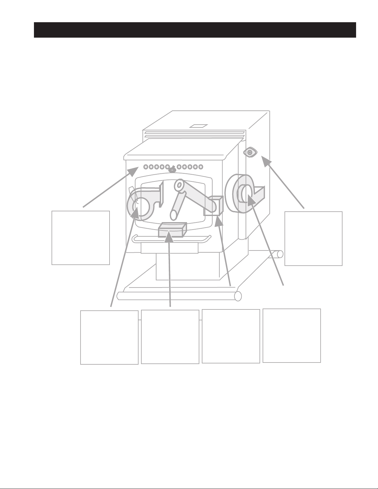
NORMAL OPERATING SOUNDS
Heat Exchange
Tubes
You will hear air
being forced through
the heat exchange
tubes by the
convection fan.
Convection Fan
The modern high
efficiency fan may
have a hum or
pulsating sound,
particularly on the high
setting. This sound
may change as the
speed is varied.
Firepot
As pellets are fed to
the firepot, a light
clicking sound may
be heard.
FIGURE 29
Auger Motor
When the auger
feeds pellets you
may hear the
intermittent buzz of
this motor running.
Thermostatic
Thermostatic
Control
Control Switch
This part can
produce a clicking
sound as it
automatically turns
the convection fan
"ON" or "OFF".
Exhaust Fan
The flow of exhaust
gasses through this
air-cooled induction
motor creates a
steady low-pitched
hum.
PAGE 31
Page 32

CARE AND MAINTENANCE
SEE THE CARE & MAINTENANCE INSTRUCTIONS FOR DETAILS ON THESE PROCEDURES.
Weekly Maintenance:
There are several areas and parts of the unit that must be inspected and cleaned at least once a week during
operation. However, depending on fuel quality and burning habits, this maintenance may have to be performed more
frequently. These are:
A. Heat exchanger tubes.
B. Ceramic log set. (Optional)
C. Brick refractory.
D. Firepot and holder.
E. Ashpan.
F. Glass and door maintenance.
1000 Pounds (1/2 ton) of Fuel Used Maintenance:
There are several areas and parts of the unit that should be inspected and cleaned after every 1000 pounds (1/2 ton)
of fuel used. These are:
Repeat items A through F.
G. Exhaust ducts.
H. Hopper and auger tube area.
6000 Pounds (3 tons) of Fuel Used Maintenance:
The 6000 pounds (3 tons) of fuel used maintenance requires disassembly of the unit and its components. We
recommend this procedure be carried out by a trained service person or your dealer. The following areas should be
inspected, cleaned and serviced after every 6000 pounds (3 tons) of fuel used.
Repeat Items A through H.
I. Exhaust fan (including exhaust duct system).
J. Convection fan.
K. Chimney system.
PAGE 32
Page 33
CARE & MAINTENANCE INSTRUCTIONS
PRIOR TO CARRYING OUT MAINTENANCE, ENSURE THE APPLIANCE IS UNPLUGGED
AND HAS COOLED DOWN SUFFICIENTLY TO HANDLE THE PARTS WITH SAFETY.
A. HEAT EXHANGER TUBES
To clean the heat exhange tubes, push the built-in
cleaner located above the door back and forth a
couple of times.
Make sure to keep the door closed while doing this to
eliminate any flyash from coming out.
After performing this procedure, you may wish to
brush any loose flyash into the ash pan.
B. CERAMIC LOG SET (OPTIONAL)
Remove the ceramic log and log holder from the firebox and brush off any flyash that may have accumulated using a stiff
brush.
Built in
Cleaner
Handle
C. FIREBRICK
Firebrick Refractory Holder
REFRACTORY
Remove the firebrick refractory by grasping it
on either side, lifting it up approximately 1/4 to
1/2", tilting it towards the front of the stove and
lifting it through the doorway out of the unit.
Brush away any flyash that may have
accumulated on the firebrick. Then vacuum or
dump the flyash into a suitable disposal
container.
Firebrick
Refractory
D. FIREPOT AND HOLDER
Remove the firepot holder by pulling it towards the front of the unit while lifting up. Once the firepot holder is removed, the
firepot can be removed by pulling it straight up and out of the holder.
Brush away any flyash that may have attached to the bottom of the firepot or firepot holder. Then vacuum or dump the
flyash into a suitable disposal container.
PAGE 33
Firepot
Firepot Holder
Page 34

CARE & MAINTENANCE INSTRUCTIONS (Cont.)
E. ASHPAN
Remove the ash pan by twisting the knob left or right and pulling the ashpan straight away from the unit.
Brush away any flyash that may have accumulated on the bottom of the pan with a brush. Then vacuum or dump the flyash into a
suitable disposal container.
FRONT VIEW WITH ASHLIP REMOVED
Ash Pan (Turn Knob to
Remove)
F. GLASS MAINTENANCE
Should soot or creosote deposits accumulate on the glass during operation, clean when the stove is cold with a non-abrasive glass
cleaner.
Inspect the gaskets on the door, glass and ashpan. If they show signs of deterioration, replace them. See your dealer for the proper
type and size of gaskets.
If the glass should break, wait until the stove and glass is cool before removing. Do not leave the fire unattended during this cool down
period as sparks could escape through the broken glass. Do not operate appliance with broken glass.
To replace the glass, simply remove the door and unscrew the glass clips. Replace the broken glass with Travis Industries Inc.
replacement glass only (available at your dealer). The replacement glass is high temperature, high shock ceramic glass 5 mm thick.
Under normal operating conditions the glass will not break.
G. EXHAUST DUCTS
To inspect and clean the exhaust ducts, it is
first necessary to remove the ashpan,
firepot assembly, and firebrick refractory.
Remove the Firebrick Refractory holder by
unscrewing the two phillips head screws
that hold it in place.
Remove Firebrick
Refractory holder
by unscrewing
the two phillips
head screws
Metal
Brackets that
hold the Side
Combustion
Air Duct in
place.
PAGE 34
Page 35

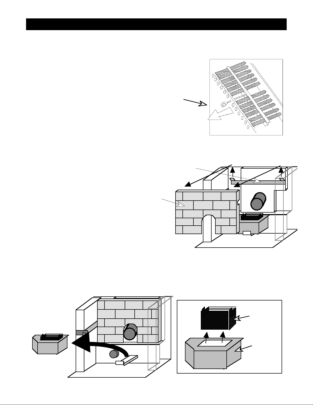
CARE & MAINTENANCE INSTRUCTIONS (Cont.)
G. EXHAUST DUCTS
(Cont.)
The next step is to remove the left or right
side exhaust duct:
Step 1 - Lift 1/4"
Step 1 ¥ Lift the side exhaust duct up 1/4"
Step 2 ¥ Pull it towards the front of the
unit
Step 3 ¥ Tilt the bottom towards the
opposite side of the unit
Step 4 ¥Pull it through the door opening
Repeat these steps for removing the
opposite side exhaust duct.
Remove the lower exhaust duct to
complete the removal of internal firebox
components.
Remove the two rear exhaust clean-outs
by prying them loose with a screwdriver
(only on certain models). They are held
in place with expaninging metal clips that
are attached to the clean-outs.
Bend a piece of piano wire or other
similar wire into an "L" shape. Use this to
insert into the space behind the rear
exhaust clean-outs and remove any
blocking flyash. There should be very
little (if any).
Step 2 -Pull
Towards Front
Step 3 - Tilt
Bottom Towards
Opposite Side
Step 4 - Pull Out Through Door Opening
Rear Exhaust
Clean-Outs
Then brush away any flyash that may have accumulated on the floor of the firebox or on the exhaust ducts with a brush.
Then vacuum or dump the flyash into a suitable disposal container.
H. HOPPER AND
AUGER TUBE
AREA
Vacuum the inside of the
hopper area and remove any
foreign objects that may have
wedged between the auger
flight and auger tube.
Fro nt
PAGE 35
Auger
Tube
Hopper
Auger Flight
Page 36

CARE & MAINTENANCE INSTRUCTIONS (Cont.)
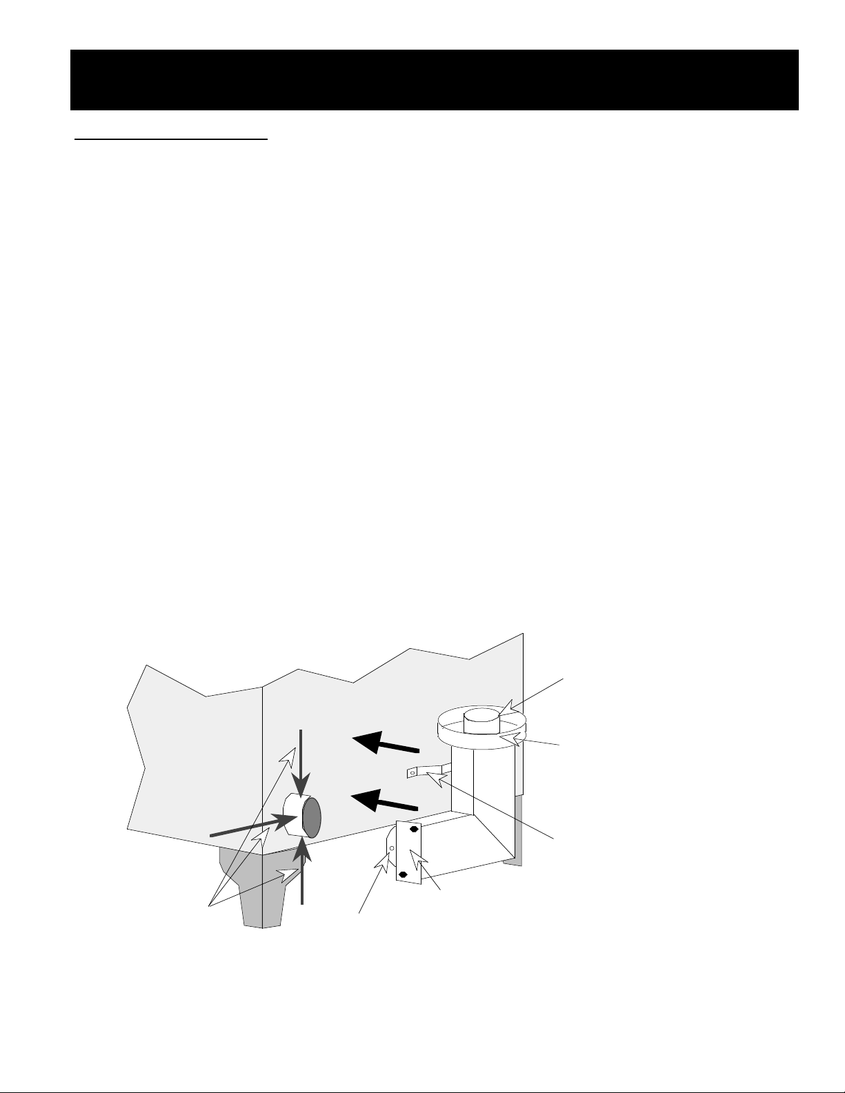
I. EXHAUST FAN
Open the left side panel by taking a standard screwdriver and turning the three screws located on the left side one-half turn
counter-clockwise. These screws are actually cogs that hold the panel in place, and only need to be turned slightly to
release. Then swing the panel back on the hinge located on the very back of the left side.
To re-attach, use a screwdriver to turn the screws one-half turn while pressing them against their sockets. See the
illustration below.
To Remove, Twist and Pull
Hinge
Fasteners (Turn
one-half revolution
with standard
screwdriver)
Next, disconnect the pellet vent/interior connector that connects to the back of the stove. With the left panel opened, use a
3/8" nut driver to remove the three mounting nuts that hold the exhaust fan in place. Two of the nuts are located on the top
of the exhaust fan while one is on the lower left and can only be accessed through a hole in the sheet metal. See the
illustration below for reference. Disconnect the two power leads going to the exhaust fan. Remove the insulation
surrounding the exhaust fan. Tilt the exhaust fan outwards and slide towards the opening to remove. With the exhaust fan
removed, check the gasketing that insulates the connection between the exhaust fan and the exhaust housing. If the
gasket has deteriorated, replace. Follow directions in reverse order to re-attach the exhaust fan. NOTE: The two electrical
leads coming from the exhaust fan are black. They are connected to a green wire and a brown wire. It does not matter
which color goes to which black exhaust fan lead.
Exhaust
Housing
To Fasten, Push and Twist
Exhaust Fan
(Lined with
Insulation)
Power Leads to
Exhaust Fan
Mounting Nuts
Once the exhaust fan is removed, place it so the side that holds the gasket is up. Check the impeller blades for any damage
and replace if necessary. Use a vacuum cleaner or brush to clear away any flyash that may have accumulated. Lubricate
the exhaust fan bearings located on both sides of the fan motor with two drops of light machine oil.
PAGE 36
Exhaust Fan
Page 37
CARE & MAINTENANCE INSTRUCTIONS (Cont.)
I. EXHAUST FAN (Cont.)
At this time you should also clean away any flyash that is on or in the exhaust housing and check to make sure the flow
switch nipple is not clogged or dirty. See the illustration below for reference.
Flow Switch Nipple (Make sure it
is not clogged - Check both ends)
Prior to replacing the fan assembly, check that the silicone seal at the fan and exhaust tube. If fractured, use Type RTV 500
degree silicone sealant to reseal the joint.
Exhaust Housing (clean any flyash) Check Silicone Seal
Oil Bearings Through These
Two Holes (2 drops each)
J. CONVECTION FAN
Open the right side panel by taking a standard screwdriver and turning the three screws located on the right side one-half
turn counter-clockwise.
These screws are actually cogs that hold the panel in place, and only need to be turned slightly to release. Then swing the
panel back on the hinge located on the very back of the left side.
To re-attach, use a screwdriver to turn the screws one-half turn while pressing them against their sockets. See the
illustration in the exhaust fan section for reference.
Hopper
Electrical Leads
From Control Box
to Switch Box
Convection Fan
Electrical Leads
Combustion Air Duct
Control Box
Convection Fan
PAGE 37
Page 38

CARE & MAINTENANCE INSTRUCTIONS (Cont.)
J. CONVECTION FAN (Cont.)
With the right side panel open, disconnect the two black
power leads coming from the motor. These two wires
must be connected to the convection fan during assembly,
but their orientation does not matter.
Take a 7/16" socket or wrench and remove the single bolt
located at the top of the convection fan.
The convection fan can now be pulled out of the unit for
cleaning and servicing. With the convection fan removed,
check the gasketing that insulates the connection between
the convection fan and the appliance. If the gasket has
deteriorated, replace. Follow directions in reverse order to
re-attach the convection fan.
Once the convection fan is removed, place it so the impeller blades are facing up. Check the impeller blades for any
damage and replace if necessary. Use a vacuum cleaner or brush to clean away any flyash that may have accumulated.
Lubricate the convection fan bearings by dropping two drops of light machine oil into the two holes located on the outward
side. Over-oiling can damage your fan.
K. CHIMNEY SYSTEM
Check the chimney system for soot and creosote build-up, and have it cleaned by a certified chimney sweep if necessary.
Wind/Rain Cap
Factory-Built Chimney Sections
Tee with Clean Out Cover
Attachment to
Pellet-Burning Appliance
PAGE 38
Page 39

BEFORE CALLING FOR SERVICE
SAVE TIME AND MONEY - CHECK THIS LIST BEFORE YOU CALL FOR SERVICE.
To eliminate unnecessary service calls, first read all the instructions in this manual carefully. The following checklist
provides possible solutions to common occurrences that are not the result of defective workmanship or materials in
this appliance. Always make sure unit is plugged in and that the circuit breaker has not tripped.
If you do have a problem that you cannot fix yourself, call the dealer where you purchased your appliance. When
calling, have this manual handy with the model, serial number and purchase date of your appliance.
Problem
Firepot overfills on start-up.
Start-up fire extinguishes
itself.
Possible Cause
Starting appliance on
"HIGH BURN" range.
Combustion air inlet blocked.
Door ajar.
Ashpan open or ajar.
Firepot not in correct position.
Lack of ignition.
Don't Call for Service
Until You Check
Burn rate control is set to the "OFF"
position.
Inlet tube is not blocked outside house.
Door is latched securely.
Ashpan is latched and sealed.
Firepot is in correct position.
Ensure firestarter is ignited.
Lazy orange flame,
smoking exhaust or firepot
overfills with pellets.
Restriction in combustion intake tube.
Door or ashpan open or ajar.
Firepot plugged.
PAGE 39
Combustion tube intake is not blocked.
Door and ashpan are latched.
Firepot is clean.
Page 40

BEFORE CALLING FOR SERVICE (Cont.)
Problem
Lazy orange flame,
smoking exhaust or firepot
overfills with pellets. (cont.)
Fire smolders.
Possible Cause
Incorrect air control setting.
Exhaust duct restricted.
Fuel.
Power outage.
Restricted exhaust.
Firepot overfilled.
Pellets are wet.
Don't Call for Service
Until You Check
Air control is set to suit burn rates.
(Open control until fire brightens up).
Flyash buildup behind exhaust ducts is
removed.
Fuel is not poor quality or wet.
Unit has power.
Exhaust is not restricted.
Refer to previous check items.
Pellets in hopper are dry and all
stored pellets are dry.
Pellets not feeding.
Auger not primed.
Hopper empty.
Start switch not pressed.
Power switch not "ON".
Appliance not plugged into power
outlet or no power available at
outlet.
Auger flight jammed by foreign
object.
PAGE 40
Auger is primed.
Hopper has pellets.
Start switch is pressed and amber
indicating light is on.
Power switch is "ON".
Appliance is plugged into outlet.
Circuit breaker or fuse has not
tripped.
Remove pellets from hopper and
check for foreign objects jammed in
auger flights.
Page 41

BEFORE CALLING FOR SERVICE (Cont.)
Problem
Smoke smell in house
and unit has gone off.
Unit has shut off and
hopper is full of pellets.
Possible Cause
Intermittent power failure has shut
unit off.
Automatic safety feature has shut
unit off.
Unit was unplugged while under full
operation.
Automatic safety feature has shut
unit off.
Auger flights jammed with foreign
object.
Don't Call for Service
Until You Check
Power is on.
Refer to "Operating Your Pellet
Stove", page 30, "Automatic Safety
Features" or wait 1/2 hour and relight. If unit won't light consult your
dealer.
Re-plug unit in and restart if
necessary.
Refer to "Operating Your Pellet
Stove", page 30, "Automatic Safety
Features" or wait 1/2 hour and relight. If unit won't light consult your
dealer.
Remove pellets from hopper and
check for foreign objects.
Fire goes out on low
burn
Air control setting is too high, blowing
flame out.
NOTE: Pellets dropping into burn pot
will cause the flame to be knocked
down but the flame should come
back; this is normal.
Firepot may not be in proper
position.
PAGE 41
Check air control.
Make adjustment to match
feed amount; low feed for low
air, high feed for high air.
To adjust it properly, look in
the burn pot; there should be
a slight movement of pellets.
Firepot is in correct position.
Page 42

REPLACEMENT PARTS LIST
All parts listed may be ordered from your AVALON 900 dealer. When ordering replacement parts, always give the
following information:
1. Part Number
2. Part Description
3. Serial Number
4. Date of Purchase
PART NUMBER PARTS DESCRIPTION
90-0191 Auger Motor
91-0291 Auger Assembly
90-0391 Exhaust Fan
90-0491 Convection Fan
92-0591* Control Panel with Switches -- FREESTANDING 92-0591, INSERT 92-0592
91-0691 Power Control Box
91-0791 Draft Flow Switch
90-0991 120° Degrees F N.O. Snap Disc
90-1091 Power Cord
90-1191 Draft Flow Switch Tube
92-1292 Firepot
90-1391 Ashpan & Door Gasket Set
A91-1491 Door Glass
92-1591 Ceramic Log
91-1691 Brick Refractory
91-1791 200˚ F. N. C., Snap Disc
PAGE 42
Page 43

LIMITED WARRANTY
TRAVIS INDUSTRIES, INC. warrants the AVALON 900-PS or PI pellet appliance to be defect-free in material and workmanship for five (5)
years from the date of purchase, with the exception of the electrical components, fans, gaskets, refractory, auger assembly, firepot and moving
parts. This does not include service call cost or any other additional charges. Check with your dealer for all costs if arranging a warranty call. The
exceptions listed are warranted for one (1) year from the date of purchase to be defect-free in material and workmanship.
Exclusions to this limited warranty include: Injury malfunction to the product, loss, damage, defect, failure to function due to accident, negligence,
misuse, improper installation, alteration or adjustment of the manufacturers settings of components, lack of proper and regular maintenance,
damage incurred while the unit is in transit, alteration, or act of God.
This limited warranty excludes damage caused by normal wear and tear, such as paint discoloration or chipping, worn or torn gasketing, eroded or
cracked refractory, etc. Also excluded is damage to the unit caused by abuse, improper installation, the use of fuel or fuel loads other than
specified by the manufacturer or use not set forth in the Owner’s Manual. An overfired condition will cause warped metal parts and discolored or
burned-off paint.
TRAVIS INDUSTRIES, INC. is free of liability for any damages caused by the unit, as well as inconvenience expenses, material and labor charges
incurred by the removal or reinstallation of any AVALON 900-PS or PI unit. Incidental or consequential damages are not covered by this
warranty. In some states, the exclusion of incidental or consequential damage may not apply.
This warranty does not cover any loss or damage incurred by the use or removal of any component or apparatus to or from the AVALON 900-
PS or PI unit without the express written permission of TRAVIS INDUSTRIES, INC. and bearing a TRAVIS INDUSTRIES, INC. label of
approval.
Any statement or representation of AVALON 900-PS or PI products and their performance contained in AVALON 900-PS or PI
advertising, packaging literature, or printed material is not part of this limited warranty.
This warranty is automatically voided if the unit’s serial number has been removed or altered in any way.
Only the original purchaser of an AVALON 900-PS or PI appliance is covered by this warranty. If the unit is used for commercial purposes,
it is excluded from this warranty.
No dealer, distributor, or similar person has the authority to represent or warrant AVALON 900-PS or PI products beyond the terms
contained within this warranty. TRAVIS INDUSTRIES, INC. assumes no liability for such warranties or representations.
THIS LIMITED WARRANTY IS THE ONLY WARRANTY SUPPLIED BY TRAVIS INDUSTRIES, INC., THE MANUFACTURER OF THE UNITS.
ALL OTHER WARRANTIES, WHETHER EXPRESS OR IMPLIED, ARE HEREBY EXPRESSLY DISCLAIMED AND PURCHASER’S RECOURSE
IS EXPRESSLY LIMITED TO THE WARRANTIES SET FORTH HEREIN.
This warranty is limited to the time frame set forth above. In some states, time limitations on warranties do not apply.
HOW TO USE YOUR AVALON 900-PS or PI FIVE-YEAR WARRANTY: If you find your unit to be defective in workmanship or material
within a 5-year period from the date of purchase contact your local authorized AVALON 900-PS or PI dealer. If your dealer is unable to
repair your unit’s defect, he may process a warranty claim through TRAVIS INDUSTRIES, INC., including the name of the dealership where you
purchased the unit, a copy of your receipt showing the date of the unit’s purchase, and the serial number on your unit. At that time, you will be
asked to ship your unit, freight charges prepaid, to TRAVIS INDUSTRIES, INC. TRAVIS INDUSTRIES, INC., at its option, will repair or replace,
free of charge, your AVALON 900-PS or PI unit if it is found to be defective in material or workmanship within the time frame stated within
this limited warranty. TRAVIS INDUSTRIES, INC. will ship your unit, freight charges prepaid by TRAVIS INDUSTRIES, INC., to your regional
distributor, or dealership.
To register your TRAVIS INDUSTRIES, INC. Five-Year Warranty, complete the enclosed warranty card and mail it within ten (10) days of the unit
purchase date to: TRAVIS INDUSTRIES, INC., 10850 117th Place N.E., Kirkland, Washington 98033.
OTHER RIGHTS:
This warranty provides you with certain legal rights. You may have additional rights, which vary from state to state, in regards to this warranty.
UNIT SERIAL NUMBER____________________________________
DATE OF PURCHASE_______________________________________
DEALER NAME AND ADDRESS : ______________________________________________________
______________________________________________________
______________________________________________________
Travis Industries, Inc. reserves the right to change, without notice, product features or specifications described.
Complete and
save for your
records
10850 117TH PLACE N.E. KIRKLAND, WA 98033
PAGE 43
Page 44
 Loading...