

Page 1
GreenStart Igniter 2 for Inserts:
Installation Instructions (SKU 94400952)
Compatibility
Flush Wood Plus Rectangular SN #1401-10265 or greater
Flush Wood Plus Arch SN #1401-10106 or greater
Flush Wood Plus Cape Cod
Large Flush Wood Insert
Small Flush Wood Insert
NOTE: Use the firebrick and igniter housing included with the insert (see the manual for details).
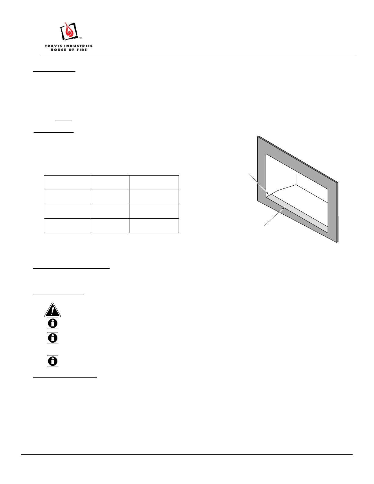
Insert Sizing
The igniter assembly, when installed, protrudes from the left
side of the insert. It requires additional space inside the
fireplace cavity for installation. See the table below for
dimensions required for installation.
Depth Into
Fireplace
Small Fl. Wd.
5” 34.75”
Insert
Flush Wood
3” 36”
Plus
Large Fl. Wd.
3” 40”
Insert
NOTE for Flush Wood Plus Rectangular: Use panel trim to
gain extra space if needed.
Width at Front
of Fireplace
Depth Into
Fireplace
Min. Width at Front
of Fireplace
Fireplace
Electrical Requirements
This kit requires 8 amps, 120 Volt AC.
Installation Tips
Do not place the compressor assembly or excess tubing inside the fireplace.
The igniter must be installed before installing the surround panels.
The compressor assembly must be placed as shown in the instructions. Placing it on its side,
near hot components, or in a location where temperatures go belo w 40 F will void the warranty
and may lead to premature failure.
You must have a ½” chuck on your drill.
Order of Installation
Remove the shipping screw from the top of the pump box.
Place insert on the hearth with the left side exposed (you may wish to place a protector over the hearth).
Install the igniter assembly.
Attach the start button the panel or trim and plug into igniter assembly.
Place the compressor assembly in a suitable location.
Route the igniter cord to the igniter assembly and attach the quick-connects and air tube.
Plug the compressor assembly into a 120v receptacle and test operation.
Page 1 of 12 17601768— 3/18/14 © Travis Industries, Inc.
Page 2
GreenStart Igniter 2 for Inserts:
Installation Instructions (SKU 94400952)
Table of Contents
Compatibility ........................................................................................................................................................ 1
Insert Sizing .......................................................................................................................................................... 1
Electrical Requirements ...................................................................................................................................... 1
Installation Tips .................................................................................................................................................... 1
Order of Installation ............................................................................................................................................. 1
Table of Contents ................................................................................................................................................. 2
Packing List .......................................................................................................................................................... 2
Igniter Installation ................................................................................................................................................ 3
Start Button Installation ...................................................................................................................................... 5
Flush Wood Plus Arch Start Button Installation: ........................................................................................................ 5
Cape Cod Flush Wood Plus Start Button Installation: ............................................................................................... 6
Cypress Face Start Button Installation: ..................................................................................................................... 7
Flush Wood Plus Rectangular Start Button Installation: ............................................................................................ 8
Placing the Compressor assembly .................................................................................................................... 9
Compressor Placement Guidelines ..................................................................................................................... 9
Routing the Igniter Cord ...................................................................................................................................... 9
Electrical Requirements....................................................................................................................................... 9
Air Requirements ................................................................................................................................................. 9
Operating Instructions ......................................................................................................................................... 10
Warnings ................................................................................................................................................................. 10
Operating Tips ........................................................................................................................................................ 10
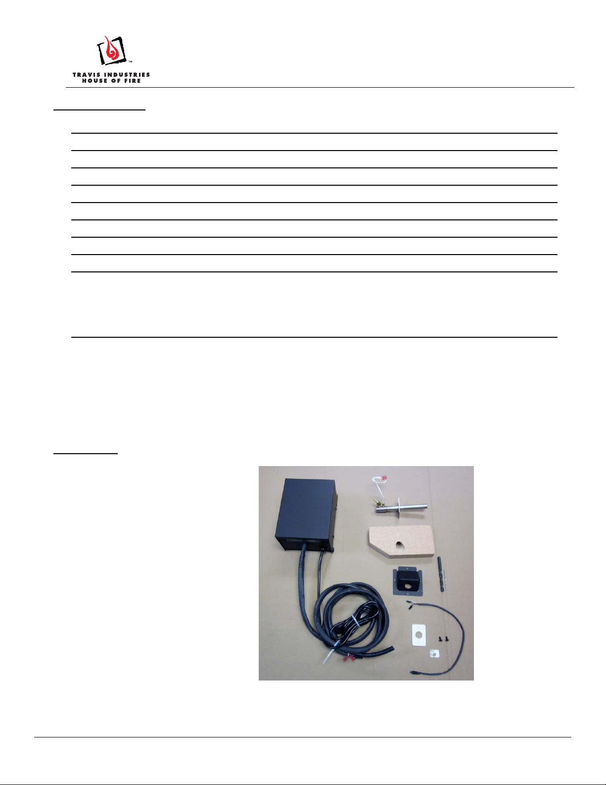
Packing List
• Compressor Assembly
• Igniter Assembly
• Igniter Firebrick
• Igniter Housing
• (1) 9/64” Drill Bit
• (1) 1/2” Drill Bit
• Power Button and Cord
• Igniter Gasket
• (2) 10-24x1/2” Screws
• GreenStart Label
Page 2 of 12 17601768.docx— 10/21/13 © Travis Industries, Inc.
Page 3
GreenStart Igniter 2 for Inserts:
Installation Instructions (SKU 94400952)
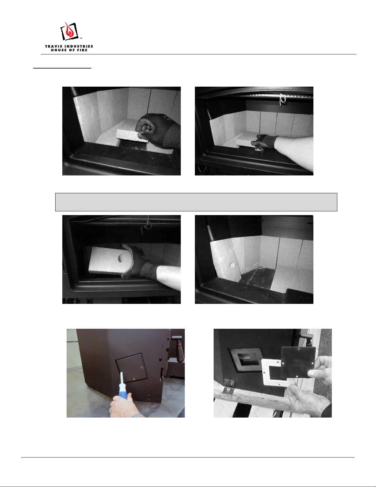
Igniter Installation
Remove the firebricks covering the igniter housing from the left of the firebox.
Install the igniter firebrick as shown below. The igniter firebrick has a special hole drilled in it that the igniter
will penetrate. Replace the 2 removed floor firebricks.
Large Flush Wood Insert
Use the fireback included with the insert (not the brick included with the kit - see manual for details).
Remove the cover plate from the side of the insert as shown below. Retain the screws and gasket.
Page 3 of 12 17601768.docx— 10/21/13 © Travis Industries, Inc.
Page 4

GreenStart Igniter 2 for Inserts:
Installation Instructions (SKU 94400952)
Attach the igniter housing to the side of the insert using the screws removed earlier, as shown below. Place
the gasket removed in step 1 between the igniter housing and insert.
Large Flush Wood Insert
Use the housing included with the insert (not the housing included with the kit - see manual for details).
Attach the igniter assembly to the housing using the screws provided, as shown below. Note that the igniter
gasket is placed between the housing and igniter assembly.
Connect the compressor hose to the igniter as shown and secure with the included hose clamp.
Connect the igniter wires. Orientation of the wires does not matter. Wrap the wires around the compressor
hose.
Page 4 of 12 17601768.docx— 10/21/13 © Travis Industries, Inc.
Page 5
GreenStart Igniter 2 for Inserts:
Installation Instructions
Start Button Installation
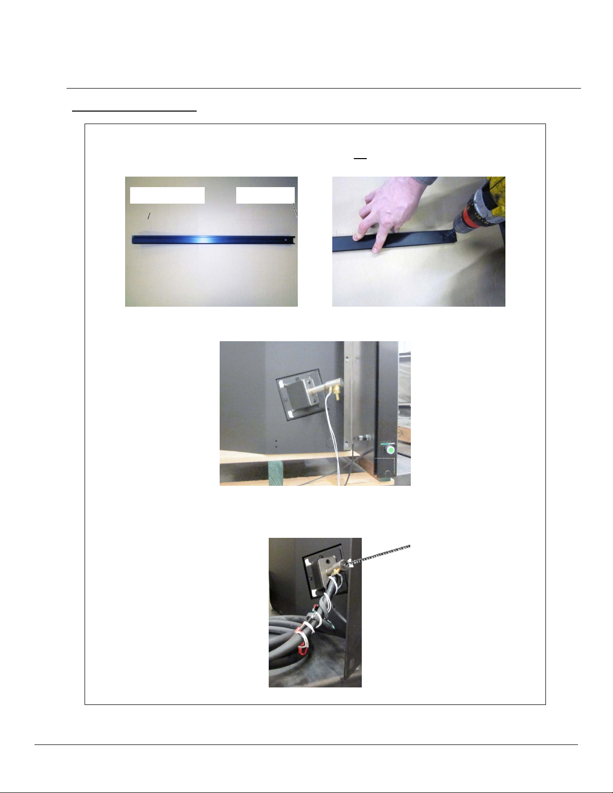
Flush Wood Plus Arch Start Button Installation:
9
Drill a
the ½” drill bit.
Affix the GreenStart sticker over the hole.
Route the On/Off switch wires through the drilled hole and install the power button.
/64” pilot hole approximately 2” from the flat end of the left side trim panel. Enlarge the hole with
Flat EndBeveled End
(SKU 94400952)
NOTE:
Use a saw to remove a
7/8” x 7/8” notch from
the rear of the trim. This
will be used to route the
igniter cord.
Attach the trim and panels, and connect the start button wires to the igniter assembly.
NOTE: The wires are color-coded and must be matched.
Page 5 of 12 17601768.docx— 10/21/13 © Travis Industries, Inc.
Page 6

GreenStart Igniter 2 for Inserts:
Installation Instructions (SKU 94400952)
Cape Cod Flush Wood Plus Start Button Installation:
9
Drill a
/64” hole approximately 2” from the flat end of the left side trim panel. Enlarge the hole with a ½”
drill bit.
Affix the GreenStart sticker over the trim panel hole, and then insert the color-coded start button wires
through the hole. The start button should be flush with the trim panel.
Connect the igniter assembly wires; orientation does not matter.
Connect the start button wires to the igniter assembly.
NOTE: The wires are color-coded and must be matched.
Page 6 of 12 17601768.docx— 10/21/13 © Travis Industries, Inc.
Page 7

GreenStart Igniter 2 for Inserts:
Installation Instructions (SKU 94400952)
Cypress Face Start Button Installation:
The Cypress Face (Flush Wood Plus and Large Flush Wood) is larger than the other faces and requires
a unique location for the GreenStart igniter button. Follow the directions below to locate and drill the
hole for the igniter button.
Remove the lower face (disconnect any wiring) and place front do wn on a non-scratching work
surface. The button location will be on the left side, inwards of the rheostat. Mark a location
approximately 1” inwards of the vertical support, centered vertically on the lower face. Use a center
punch and pilot drill to drill through the lower face. Then flip the lower face over and drill the ½”
button-mounting hole (make sure to protect all wiring). Mount the button in this location.
Affix the GreenStart sticker over the hole, and then insert the color-coded start button wires through the
hole. The start button should be flush with the trim panel.
Connect the igniter assembly wires; orientation does not matter.
Connect the start button wires to the igniter assembly.
NOTE
: The wires are color-coded and must be matched.
Route the igniter cord behind the surround panel.
Page 7 of 12 17601768.docx— 10/21/13 © Travis Industries, Inc.
Page 8

GreenStart Igniter 2 for Inserts:
Installation Instructions (SKU 94400952)
Flush Wood Plus Rectangular Start Button Installation:
9
Drill a
/64” pilot hole for the power cord that is 2” from the bottom and 4” from the right edge of the
surround panel. Enlarge the hole with a ½” drill bit.
Insert the color-coded start button through the hole. The start button should be flush with the surround
panel.
Route the igniter cord through the “mouse hole” in the left side of the panel as shown above. Attach the
face to the panel.
Connect the igniter assembly wires; orientation does not matter. Wrap the wires around the compressor
hose.
4”
2”
Connect the igniter assembly wires; orientation does not matter.
Connect the start button wires to the igniter assembly.
NOTE: The wires are color-coded and must be matched.
Page 8 of 12 17601768.docx— 10/21/13 © Travis Industries, Inc.
Page 9

GreenStart Igniter 2 for Inserts:
Installation Instructions (SKU 94400952)
Placing the Compressor assembly
Compressor Placement Guidelines
The compressor assembly may be placed on the floor or hearth, away from the insert (do not place in
front of the insert). It may also be placed in a ventilated enclosure or remote location. The guidelines
below outline the requirements for placing the igniter assembly. If it is placed in a remote location, make
sure it is accessible and meets all of the requirements listed below and any local building codes.
Typical installation locations may include:
• Decorative Enclosure
• Behind Cabinet, Bookcase, or Furniture
• Remote, Dry Locations: crawl space or attic enclosure
NOTE: DO NOT place the compressor assembly inside the fireplace cavity or outside the house.
Routing the Igniter Cord
The igniter cord is 9’ long and requires a 1” diameter hole for routing through partitions. If placed in a
remote location, seal any holes to prevent air infiltration.
Electrical Requirements
The igniter assembly uses a standard 120v plug and requires an accessible receptacle. The igniter
system draws 8 amps (you may wish to place this system on a dedicated circuit). If placed in a remote
location, we recommend you a GFCI circuit breaker (this allows for safe operation and eliminat es the
need to access the igniter assembly). Consult your local building official for requirements in your location.
Air Requirements
The igniter assembly utilizes a 2 CFM compressor. If making an enclosure, make sure to accommodate
enough air input to allow the igniter assembly to operate correctly. If the igniter assembly is placed in an
external location such as an attic or crawl space, make sure to keep insulation or excessive dust or dirt
from entering the igniter assembly.
WARNING: DO NOT place the compressor assembly inside the fireplace cavity, and do not place it on its
side or upside down.
Page 9 of 12 17601768.docx— 10/21/13 © Travis Industries, Inc.
Page 10

GreenStart Igniter 2 for Inserts:
Operating Instructions
Warnings
The igniter must be operated only with someone present. Improper operation may lead to smoke
entering the home.
MAKE SURE THE AIR CONTROL AND BYPASS ARE OPEN (IF APPLICABLE). FAILURE
TO OPEN THESE CONTROLS MAY LEAD TO SMOKE ENTERING THE HOME.
DO NOT OPEN THE DOOR DURING IGNITION. THIS MAY LEAD TO SMOKE ENTERING
THE HOME.
DO NOT PLACE YOUR HAND NEAR THE IGNITER OPENING. THIS AREA BECOMES
EXTREMELY HOT AND MAY CAUSE SEVERE BURNS.
Operating Tips
The compressor assembly will turn on for 30 seconds when it is first plugged in. This is normal.
Hardwood or un-seasoned wood may take longer to ignite. For this kind of wood you may need to
cut the kindling into smaller pieces.
Wood placement is the key to building a good fire. Experiment with different sizes of wood and
wood placement until you find a method that works best for your wood quality and kindling.
Installation Instructions (SKU 94400952)
Make sure to place the wood within 1” of the igniter opening.
1. Place two pieces of wood front to back opening on the firebox floor (or ashbed) as shown below.
NOTE: These pieces should be placed to elevate the next course of kindling to a position next to the
igniter opening.
Page 10 of 12 17601768.docx— 10/21/13 © Travis Industries, Inc.
Page 11

GreenStart Igniter 2 for Inserts:
Installation Instructions (SKU 94400952)
2. This next piece of wood is the key. It should be approximately 2-3” in diameter with no bark. Place it
directly behind the igniter opening, parallel with the door opening. Done correctly, this piece will
ignite along its entire length, starting the fire quickly and burning long enough to light the other pieces.
Igniter
Opening
3. Place additional pieces of wood directly in front and in back of the piece of wood placed in step 2. Make
sure the wood runs parallel to the igniter air flow and is spaced far enough apart to allow air to flow.
Igniter
Air Flow
4. Continue to stack your kindling in a criss-cross pattern. Make sure to provide enough room for air
flow. Bigger pieces may be stacked on top of the pile.
Page 11 of 12 17601768.docx— 10/21/13 © Travis Industries, Inc.
Page 12

GreenStart Igniter 2 for Inserts:
Installation Instructions (SKU 94400952)
5. Make sure the air control and bypass are in the open position.
6. Close the stove door when all kindling is in place.
7. Press the igniter button to start the ignition process.
The green indicator light on the button will turn on.
The igniter and compressor assembly will run for 15
minutes before shutting off automatically.
NOTE: If you need to turn off the igniter after starting the ignition process, press the GreenStart button a
second time. The system will turn off power to the igniter and the GreenStart button will flash. The pump
will continue to run for about seven minutes and then shut off.
ADDED FEATURE – “BELLOWS ONLY”:
If a bellows effect is desired (adding oxygen to the fire without cycling the igniter) simply push the
GreenStart button twice, which will start the pump-only mode. The bellows effect will stay on for 7
minutes, before the unit shuts down.
Page 12 of 12 17601768.docx— 10/21/13 © Travis Industries, Inc.
 Loading...