

Page 1
Fan, Cypress / GreenField
Installation Instructions (sku 99000173)
Packing List
• Blower Assembly
• Wiring Harness
• Rheostat
• Snap Disc
• Rheostat Nut, Spacer, and Knob
Warnings
WARNING: Make sure power to the stove has been shut off prior to installation (Unplug the stove).
Do not connect 110-120 VAC to the gas control valve or wiring system of this appliance.
NOTE
: Install the blower prior to connecting the gas line or installing the stove. If using the
GreenSmart™ remote, install it after the blower is in place.
NOTE
: If using the GreenSmart™ remote, refer to the special instructions below (GS1 or GS2). When
using the GreenSmart™ remote, certain installation steps may be disregarded or altered.
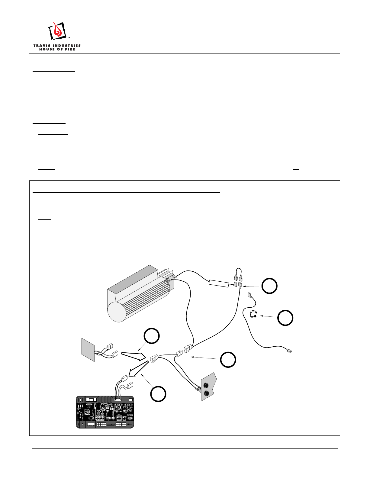
Special Instructions for GreenSmart™ 2 Remote (GS2)
When using the GS2 remote, power for the blower is routed through the fuse and IFC, bypassing the rheostat and snap disc
included with the blower kit (these items may be kept for spare parts).
HINT: Install the blower(s) with the IFC removed. Connect the wiring as shown below.
Disconnect the blower power input (see “a” below).Connect the blower wiring harness to the fuse output (see “b” below).
Disconnect and discard the electrical line intended to connect the snap disk to the rheostat (carefully remove the wire tie
from the wiring harness – see “c”). Attach the jumper wire (included with the remote) to the wires labeled “SNAP DISC”
(see “d” below). Attach the blower power input (see “e”) to “FAN” lead on the fuse harness (pre-connected to the IFC).
This circuit bypasses the rheostat and snap disc (these components included with the blower kit are not used and may b e
kept for replacement part purposes).
SNAP DISC
d
c
POWER INPUT
a
b
3.15
A
FUS
E
Page 1 of 6 17601635 - 9/6/13 © Travis Industries, Inc.
e
Page 2
Fan, Cypress / GreenField
Installation Instructions (sku 99000173)
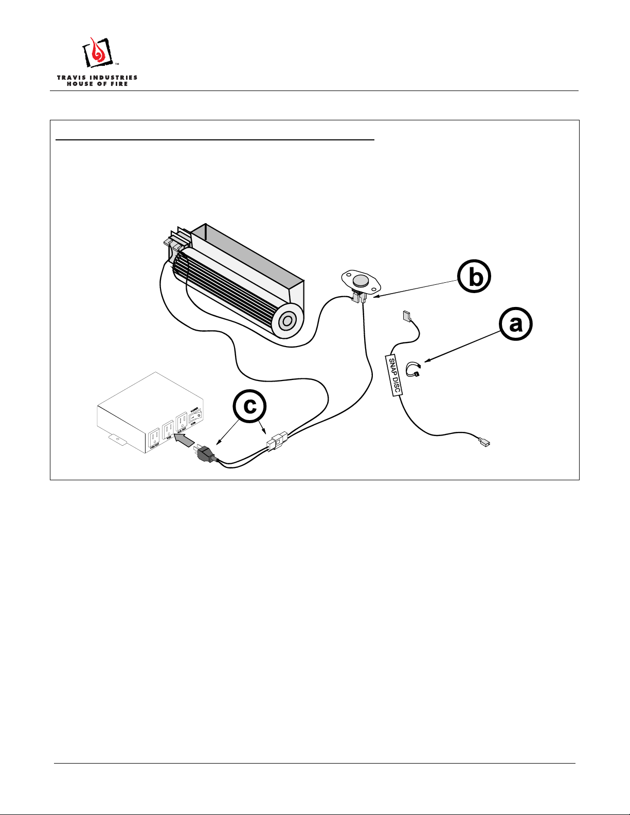
Special Instructions for GreenSmart™ 1 Remote (GS1)
When using the GS1 remote, the rheostat is bypassed and the power connected to the fan extension module.
Disconnect and discard the electrical line that leads from the snap disk to the rheostat (carefully remove the wire tie and
“SNAP DISK” label from the wiring harness – see “a”). Attach the lead from the power input to the snap disk (see “b”). Attach
the wiring harness molex to the power lead (included with the remote – see “c”). Then plug the power lead into the outlet
labeled “FAN” on the fan control module. Disregard the instructions for installing the rheo stat (steps 6 through 9) or attaching
power to the wiring harness (step 4).
Page 2 of 6 17601635 - 9/6/13 © Travis Industries, Inc.
Page 3

Fan, Cypress / GreenField
Installation Instructions (sku 99000173)
Installation
1 Use pliers to disconnect the cord restraint from the power cord (see Figure 1).
Figure 1
2 Remove the seven screws holding the rear cover in place (see Figure 2 and Figure 3). Remove the rear
cover and place it directly behind the stove.
Figure 2
Figure 3
3 Disconnect the molex connector from the power cord (see Figure 4). Place the power cord aside. The rear
cover may be discarded.
Figure 4
Page 3 of 6 17601635 - 9/6/13 © Travis Industries, Inc.
Page 4

Fan, Cypress / GreenField
Installation Instructions (sku 99000173)
4 Remove the cover plate behind the gas control valve (see Figure 5). Attach the included snap disc in this
location using the same screws (see Figure 6).
Figure 5 Figure 6
5 Place the blower near the back of the stove and attach the two wires on the wiring harness labeled
“BLOWER” to the blower (orientation does not matter – see Figure 7). Attach the two wires labeled “SNAP
DISC” to the snap disc (orientation does not matter – see Figure 8).
Figure 7
Figure 8
6 Insert the power cord through the hole on the power housing (see Figure 9). Place the cord restraint over
the power cord and press into the hole on the blower assembly, locking the power cord in place (see Figure
10).
NOTE
: The blower assembly has three hole locations for the power cord power to exit the stove (left, right,
and center). Use the hole best suited for your installation.
Figure 9
Figure 10
Page 4 of 6 17601635 - 9/6/13 © Travis Industries, Inc.
Page 5

Fan, Cypress / GreenField
Installation Instructions (sku 99000173)
7 Attach the molex from the power cord to the molex disconnected in step 3 (see Figure 11).
Figure 11
8 Attach the molex connector on the blower wiring harness to the molex connector on the stove (see Figure
12). Attach the two wires labeled “RHEOSTAT” to the rheostat included with this kit (see Figure 13).
Figure 12
Figure 13
9 Remove the four screws holding the control panel in place (see Figure 14). Pull the control panel forward
and lay it face down (see Figure 15).
NOTE: Remove the battery trays before removing the control panel.
WARNING
: Take care to prevent scratching the control panel door (use cardboard or paper).
Figure 14
Figure 15
Page 5 of 6 17601635 - 9/6/13 © Travis Industries, Inc.
Page 6

Fan, Cypress / GreenField
Installation Instructions (sku 99000173)
10 Carefully route the rheostat under the firebox to a location near the control panel (route the wires under the
components to prevent wiring from contacting the hot firebox floor). Insert the spacer onto the rheostat
shaft and insert it into the hole next to the accent light rheostat (see Figure 16). Make sure the orientationtab on the rheostat lines up with the orientation-hole on in the control panel. Use the included press-nut to
secure the rheostat to the control panel (see Figure 17). Carefully replace the control panel, making sure
wires do not pinch, and attach with the four screws removed in step 9. Place the rheostat knob on the
rheostat.
Figure 16
Figure 17
11 Before attaching the blower assembly, verify all wiring is secure and does not contact any moving or hot
surfaces. Use wire ties, if necessary, to secure the wiring. Attach the blower assembly using the screws
removed in step 2 (see Figure 18) and return the stove to the correct configuration.
Figure 18
Page 6 of 6 17601635 - 9/6/13 © Travis Industries, Inc.
 Loading...