

Page 1
DESIGNAVALON
P
URE
C
LASS
A M
USIC
R
ECORDING
S
YSTEMS
VT-747SP
Operation Manual
Pure Class A Stereo Spectral Opto-Compressor Equalizer
© 2001 Avalon Industries Incorporated. Release 1.0.
Page 2

AVALON DESIGN
P
URE
C
LASS
A M
USIC
R
ECORDING
S
YSTEMS
VT-747SP
Operation Manual
Avalon Industries, Inc., PO Box 5976, San Clemente, CA 92673
Tel: 949-492-2000 Fax: 949-492-4284 www.avalondesign.com
Page 3

AVALON DESIGN
P
URE
C
LASS
A M
USIC
R
ECORDING
S
YSTEMS
Table of Contents
1.0 Introduction . . . . . . . . . . . . . . . . . . .4
1.1 Overview . . . . . . . . . . . . . . . . . . .4
1.2 Features . . . . . . . . . . . . . . . . . . . .5
1.3 Unpacking and Inspection . . . . . . .6
2.0 Quick Start-up . . . . . . . . . . . . . . . . .7
2.1 Quick Set-up Guide . . . . . . . . . . .8
2.2 Tips . . . . . . . . . . . . . . . . . . . . . . .9
2.3 Tutorial-Using it all . . . . . . . . . . . .9
3.0 Safety and Grounding . . . . . . . . . .10
3.1 Safety Instructions . . . . . . . . . . .10
3.2 Grounding Instructions . . . . . . . .10
3.3 AC Voltage Selection . . . . . . . . . .11
3.4 Fuse Replacement . . . . . . . . . . .12
3.4 Rack Mounting and Cooling . . . .12
3.5 Turn-on Procedure . . . . . . . . . . .13
4.0 Operation and Controls . . . . . . . . .14
4.1 Rear Panel Description . . . . . . . .17
4.2 Connections . . . . . . . . . . . . . . . .17
4.3 Unbalanced Operation . . . . . . . .17
4.4 Using the Vt-747sp . . . . . . . . . . .18
4.5 Six Band Passive Equalizer . . . .18
4.6 Using the Equalizer . . . . . . . . . . .18
4.7 Using the Side-chain . . . . . . . . . .19
5.0 Applications . . . . . . . . . . . . . . . . . .19
5.1.0 Typical Set-ups . . . . . . . . . . . .19
5.1.1 Recording . . . . . . . . . . . . . . . . . . .20
5.1.2 Stereo Mixdown (Buss) . . . . . . . . .20
5.1.3 Mixdown/Mastering - DAW . . . . . . .20
5.1.4 Mastering . . . . . . . . . . . . . . . . . . .21
5.2.0 Application Settings . . . . . . . . .21
5.2.1 Stereo Buss for Mixdown . . . . . . . .21
5.2.2 Stereo Buss with De-ess . . . . . . . .22
5.2.3 De-ess on Vocals . . . . . . . . . . . . .22
5.2.4 Stereo Keyboards . . . . . . . . . . . . .23
5.2.5 Extreme Compression Effect . . . . .23
5.2.6 Acoustic Piano . . . . . . . . . . . . . . . .24
5.2.7 Acoustic Guitar . . . . . . . . . . . . . . .24
5.2.8 Drum Overheads . . . . . . . . . . . . . .25
6.0 Compression Primer . . . . . . . . . . .25
6.1 Equalization Primer . . . . . . . . . . . .27
7.0 FAQs . . . . . . . . . . . . . . . . . . . . . . . .27
8.0 Trouble Shooting . . . . . . . . . . . . . .30
9.0 Service and Contact Information . .32
10.0 Technical Information . . . . . . . . .33
10.1 Recall Sheet . . . . . . . . . . . . . . .34
10.2 Block Diagram . . . . . . . . . . . . .35
11.0 Warranty . . . . . . . . . . . . . . . . . . . .36
11.1 Returns . . . . . . . . . . . . . . . . . . .36
12.0 Safety Standards . . . . . . . . . . . . .36
Appendix A - Glossary . . . . . . . . . . . . .37
Page 4
Page 4 Avalon Vt-747sp Operation Manual
AVALON DESIGN
Introduction
1.0 Introduction
Welcome to Avalon and the world of high
performance Pure Class A music recording
systems. The Vt-747sp is an extremely
versatile, pure Class A, vacuum tube/discrete
TSP (Tube Signal Path) stereo optocompressor and program equalizer.
The Vt-747sp is the most creative and flexible
stereo compressor available. With TSP(Tube
Signal Path), the Vt-747sp uses three hand
selected vacuum tubes in the signal path for
warm tube tone or bypasses the tubes for
classic Class Adiscrete transistor sound. Also
featured on the Vt-747sp is a passive sixband graphic equalizer for gentle toneshaping plus a two-band parametric EQ for
complete spectral side-chain or musical
control.
The Vt-747sp is hand built in the USA using
only the finest active and passive electronic
components available. Many of these parts
have been custom-manufactured exclusively
for Avalon. A "no compromise" approach in
every stage of design and production ensures
that the Vt-747sp will give many years of
dependable high-quality service.
Please take a moment to read this manual
and enjoy your Avalon experience!
1.1 Overview
The Vt-747sp combines a stereo tube/
discrete Class A opto-compressor with a
musical six-band program equalizer, as well
as Left/Right output level, gain reduction
metering and an internal regulated power
supply in a 2U space. Ideal for high
performance DAW (digital audio workstation)
input signal conditioning, stereo buss
compression/EQ, stereo keyboards and
mastering applications.
The Vt-747sp features a minimum signal path
design utilizing sealed silver relays for all
signal routing and bypass functions.
Compression with the Vt-747sp is achieved
with twin optical attenuators that act as
passive level controllers together with a Class
A variable gain make-up amplifier. Full
dynamic control from soft compression to
hard-knee limiting can be achieved with
master threshold, compression ratio, attack
and release controls. Gain reduction
indication is a large analog VU meter. Low
and High Frequency (LF and HF) contour
parametric spectral controls can be routed
into the on-board side-chain path for
enhanced frequency dependent compression
with variable frequency and threshold levels.
An SC LISTEN switch provides side chain
listen mode for easy monitoring.
Page 5
The Vt-747sp equalizer utilizes 100%
discrete, Class A high voltage transistors for
optimum sonic performance. The six-band
stereo program EQ incorporates the smooth
characteristics of an all passive design. The
frequency turnover, Q and amplitude ranges
have been carefully chosen for each band to
provide the most natural harmonic balance
with lowest phase change while offering
simple and effective tone control. The EQ can
be placed pre or post compressor for
enhanced effects.
The Vt-747sp features TSP (Tube Signal
Path) which gives you the choice of either
tube tone (utilizing three high-voltage dual
triode tubes), or the classic, Class A discrete
transistor sound (utilizing discrete transistor
amplifiers) in the primary opto buffers and
output stages.
Fully balanced DC coupled, Class A discrete
amplifiers are utilized for the input and output
drive interface with +36dB input headroom. A
high quality analog VU meter indicates
accurate gain reduction. Twin LED meters
provide a 60dB range with fast L-R output
status of all levels.
1.2 Features
Class A optical compression
100% discrete Pure Class A operation
Built-in side chain for spectral control
Six-band discrete graphic passive EQ
TSP (Tube Signal Path) with bypass
EQ pre/post compression selection
Twenty-two silver relays for signal routing
True hard-wire bypass
Low noise, better than -92dB
High operating headroom +36dB
Fully balanced operation, input and output
3 military-grade dual triode vacuum tubes
High voltage, high current signal path
Rugged stainless steel metric hardware
2U nineteen inch welded steel chassis
Switchable AC power supply 100-240v
150W toroidal shielded power transformer
Discrete soft-start DC power regulators
Page 5
Avalon Vt-747sp Operation Manual
AVALON DESIGN
Introduction
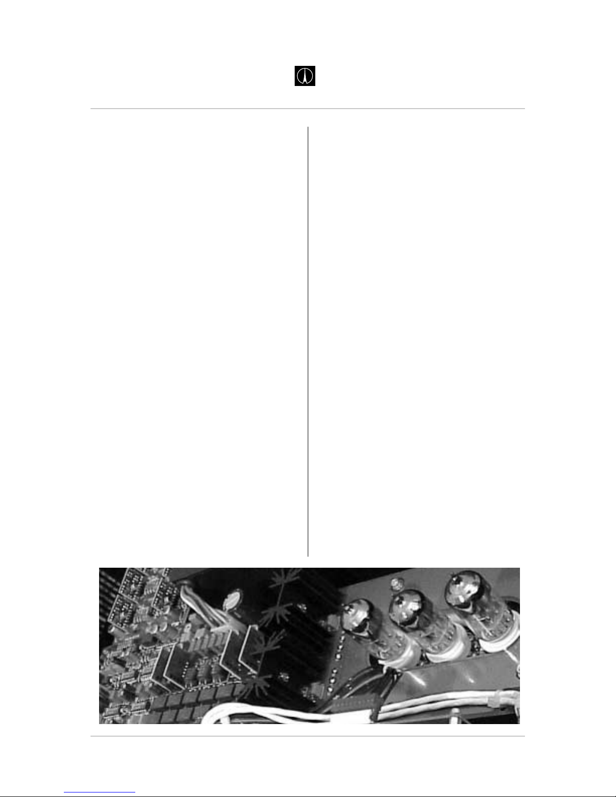
Inside view of Vt-747SP
Page 6
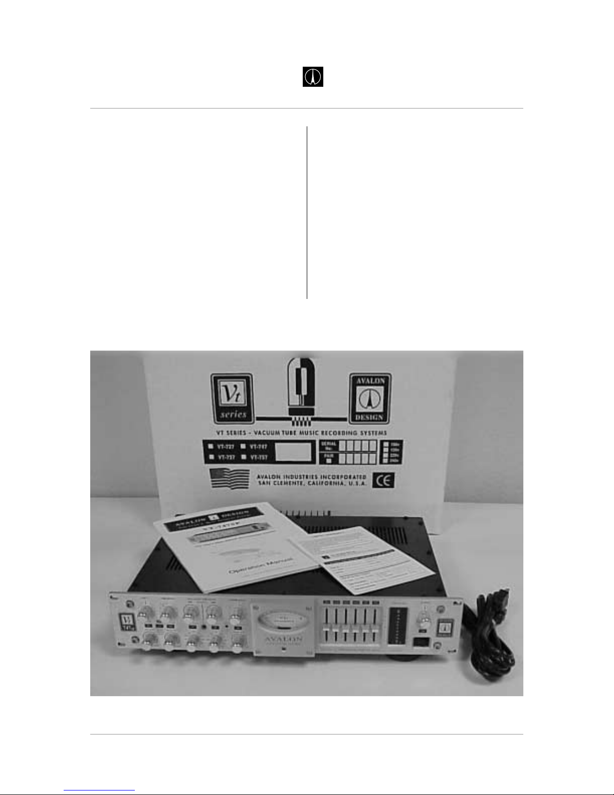
1.3 Unpacking and Inspection
Your Vt-747sp was packed carefully at the
factory. Check to make sure that the shipping
carton contains the following items:
1. Vt-747sp
2. Power cable
3. Warranty card
4. Operation Manual
Keep the packing materials in case you need
to ship your unit for any reason.
Note: You must fill out and send in your
warranty card in order to receive warranty
and technical support. If you have not
already filled out your warranty card please
take the time to do so now.
Page 6 Avalon Vt-747sp Operation Manual
AVALON DESIGN
Introduction
Vt-747sp contents and packaging
Page 7
2.0 Quick Start-up
The following chapter is designed to help you
get started using your Vt-747sp right away
without having to read the entire manual.
Make sure however to take time to read the
manual at a later date as there are many
safety aspects and features of the Vt-747sp
that will not be discussed here.
If you are familiar with this type of equipment
you can also familiarize yourself with your
Vt-747sp and the functions with the Quick
Set-up Guide on page 8.
Note: The Vt-747sp is an extremely high
performance piece of musical equipment.
Every setting has great potential for
musicality. Do not be afraid of turning the
knobs or faders to their full extreme
positions.
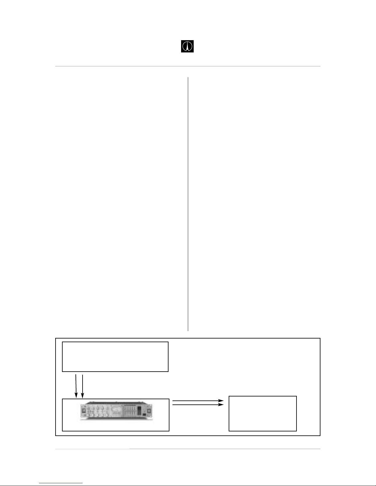
Hook it up, turn it on and play:
1. Check on the rear of your unit that the
power supply is set for your local AC
voltage. (120V in U.S.) Refer to Chapter 3
page 11 for details.
2. Plug in the AC power cable and connect
your Vt-747sp to your stereo source. (XLR
type connectors pin 2 is hot.) You can use
the Vt-747sp in mono, however, the Left
and Right will always work together as one
dedicated stereo pair.
3. Turn on the power and allow 60 seconds
while the soft-start procedure commences.
You may hear a relay click at about 45
seconds. During the soft-start procedure,
the Vt-747sp is in hard-wire bypass mode
and will pass signal, but the controls will
not work. For optimum performance,
allow 30 minutes for the Vt-747sp to
fully warm up.
4. With all switches in the disengaged or nonilluminated position, run a signal through
the Vt-747sp. Use the output control on the
right hand side of the unit to check basic
operation.(see figure 2.0 below)
5. Now you are ready to start pressing
switches, turning knobs and pushing EQ
faders!
The Quick Set-Up Guide on the following
page gives a brief description of the switches
and controls on the Vt-747sp.
Page 7
Avalon Vt-747sp Operation Manual
AVALON DESIGN
Quick Start-up
figure 2.0 Quick Start up
Keyboard or Stereo Source
Right and Left Outputs
Outputs
Right and Left Inputs
Vt-747sp
Inputs
Mixing Console
or
Monitoring System
Page 8
Page 8 Avalon Vt-747sp Operation Manual
AVALON DESIGN
Quick Start-up
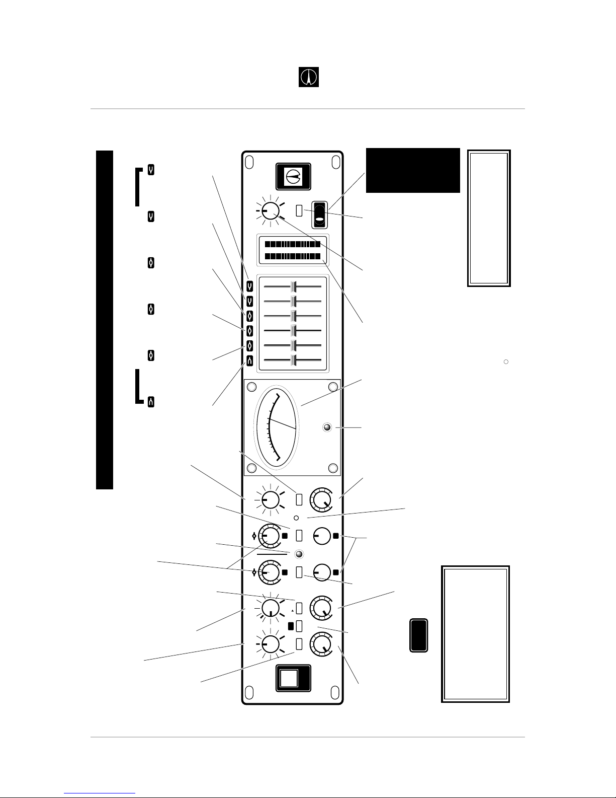
TSP
Twin Signal Path
Switch (in) swaps
three (3) tubes
into the audio
path from discrete
Class A amps.
F4
Boost-cut
sets amplitude
of mid-range
-4dB to +4dB
detent at 0dB
2kHz
peak-dip
FI
Boost-cut
sets amplitude
of low-bass
-24dB to +24dB
detent at 0dB
15Hz
shelf
F2
Boost-cut
sets amplitude
of mid-bass
-8dB to +8dB
detent at 0dB
125Hz
peak-dip
F3
Boost-cut
sets amplitude
of low-mid
-4dB to +4dB
detent at 0dB
500Hz
peak-dip
F5
Boost-cut
sets amplitude
of presence
-10dB to +10dB
detent at 0dB
5kHz
shelf
F6
Boost-cut
sets amplitude
of treble
-20dB to +20dB
detent at 0dB
32kHz
shelf
20
10
3
2
AVALON
VACUUM TUBE
-
7
5
3
1
0
1
2
d
e
c
i
b
e
l
s
V
U
+
IN IN IN IN INININ
HF
v
747
sp
t
-
dB+
-15 +15 -15 +15
0dB
+2 +6
+10
SIDE-CHAIN THRESHOLD
CONTOUR
GR
SC LISTENSIDE-CHAIN
CAL
GR
GAIN
+10dB
60
100
80
160 250
300
400
1k
Hz
70 600
200
600
1k
800
1k6 2k5
3k
4k
10k
Hz
700 6k
2k
LF
TSP
EQ COMP
INPUT
0
20 8
32
46
610
11
FAST SLOW
ATTACK
TUBE
SIGNAL
PATH
FAST SLOW
RELEASE
GAIN
MAKE-UP
COMPRESSOR
METER
RATIO
COMPRESSION
120
47
83
102
65
-
dB+
THRESHOLD
20 20
0
6
10
-
10
1615
3+2
DESIGN
AVALO N
0
123
321
+
-
CLASS A PROGRAM EQUALIZER LEVEL
SIGNAL
-
dB+
OUTPUT
0
20 6
22
34
48
11
EQUALIZER
R
dB
L
30
0
24
18
12
+
-
12
6
6
182430
VT-747SP QUICK SET-UP OPERATING GUIDE
+10dB switch
Boosts input
amplifier by
+10dB for extra
tube over-drive
INPUT GAIN
Trims input level
-20dB to +8dB
detent at 0dB
(+18dB with +10dB IN)
LF and HF THRE
S
H
O
LD
Range -15dB to +15dB, detent at 0dB,
clockwise rotation raises the threshold
(less compression) and counter clockwise
rotation lowers the threshold (more compression)
at the frequencies set by the LF (low frequency)
and HF (high-frequency) spectral frequency
controls located directly below
THRESHOLD
Sets compressor
input threshold
from -30dB to
+20dB
COMPRESSION
Sets ratio of
compressor
from 1:1 to 20:1
COMPRESSOR
Switch (in) engages
compressor into
signal path
(hard-wire bypass)
SIX (6) BAND PASSIVE CLASS A, PROGRAM EQUALIZER
EQ to COMP
Inserts the
six (6) band
EQ pre the
compressor
Blue LED
Indicates
compressor
speed and
activation
SC Listen
Switch (in)
for Spectral EQ
into audio path
to monitor SC
ATTACK
Variable attack
time for the
compressor
2mS to 200mS
RELEASE
Variable release
time for the
compressor
100mS to 5S
SPECTRAL
Sweep frequency
for LF and HF
bands, used with
above threshold
controls
SIDE-CHAIN
Inserts spectral
EQ into side-
chain
METER
Recessed
screwdriver
adjust for 0dB
gain-reduction
meter trim.
AC POWER
Note: Check
rear power input
connector for
correct local
ac voltage. Allow
forty seconds for
the soft-start
procedure to
activate the
the audio
signal path.
AVALON
Class A Vacuum Tube
STEREO SPECTRAL OPTO-COMPRESSOR WITH TSP
POWER LED
Indicates ac
power is on
MAKE-UP
0dB to +10dB
variable gain on
opto-compressor
METER
High quality
VU meter
indicates
gain reduction
0dB to -20dB
VT-747SP
Avalon Design is a division of Avalon Industries, Inc. 2001
c
OUTPUT METER
Fast LED meter
indicates both L-R
spectral content
and output level
-30dB to +30dB
OUTPUT LEVEL
Stereo output
level control
-20dB to +6dB
detent at 0dB
EQ
Switch (in)
activates 6 band
passive EQ into
audio path
(hard-wire bypass)
Note:
For the best sonic performance,
allow thirty minutes for warm-up.
When not in use, turn the ac off. This will
extend the life of the electronics . . Enjoy!
Note:
Knob settings shown represent
starting positions only.
TSP
TWIN SIGNAL PATH
All units in dBu.
Figure 2.1 Quick Set-up Guide
Page 9

2.2 Tips
Unity Level - The Vt-747sp is calibrated so
that unity level is +4dBu.
INPUT - Use the input control as a gain
control, not a level control. This will drive the
tubes and/or transistors harder for different
tone.
OUTPUT - Use the output control as the
overall level control.
TSP (Tube Signal Path) - Pressed in
(illuminated) is tube mode. Pressed out (nonilluminated) discrete Class A mode.
EQ > COMP - Inserts the six-band graphic
EQ before (pre) the compressor in the signal
path.
SIDE-CHAIN - Engages the built-in sidechain. Use the SIDE CHAIN THRESHOLD
and the corresponding frequency bands to
compress specific frequencies.
SC LISTEN - To monitor the signal through
the side chain.
GR (Blue LED) - Fast-acting LED illuminates
when peak gain reduction begins to occur.
EQ - Six-band graphic EQ parameters:
Low to high (left to right)
+/-24dB 15Hz shelf
+/-8dB 125Hz selected Q
+/-4dB 500Hz selected Q
+/-4dB 2kHz selected Q
+/-10dB 5kHz shelf
+/-20dB 32kHz shelf
2.3 Tutorial - Using it all
The following is a tutorial that will quickly get
you familiar with all of the functions of the
Vt-747sp.
Start by plugging a stereo source (CD player,
stereo keyboard, Submix output, etc.) into
your Vt-747sp. If possible, run directly out of
the Vt-747sp to powered monitors bypassing
the console or mixing board. Choose a
musical selection, loop, patch, sample or
instrument with wide dynamic range so you
can experiment with the compressor.
Set push button switches to their off or nonilluminated position.
1. INPUT - Set to 5. (Adjust OUTPUT so that
overall signal level is at a comfortable
monitoring level.
2. GAIN +10dB - Press in and out to get a feel
for the sound of the high gain switch. Leave
it non-illuminated.
3. EQUALIZER - (Located on right side of
panel) press in equalizer switch and
familiarize yourself with the six band
equalizer. Adjust the two outside bands half
way between unity and maximum, and the
four mid-bands to half way between unity and
minimum. Toggle the EQUALIZER switch in
and out.
4. COMPRESSOR - Press in COMPRESSOR
switchand turn the main compression controls
to the following:
COMPRESSION - fully clockwise
THRESHOLD - fully counter clockwise
ATTACK - fully counter clockwise (Fast)
RELEASE - fully clockwise (Slow)
Page 9
Avalon Vt-747sp Operation Manual
AVALON DESIGN
Quick Start-up
Page 10
5. EQ->COMP - Press in to insert the EQ
before (pre) the compressor in the signal
path.
6. Press in TSP. This will engage the tubes
so that you are now in tube mode.
7. Press in SIDE CHAIN and SC LISTEN. You
are now monitoring the signal going through
the side chain. You can use the side chain
listen function as a parametric EQ on the
primary audio path.
8. Adjust the side chain parameters to the
following settings:
Both LF and HF side chain threshold fully
counter clockwise.
LF frequency set to 300 Hz.
HF frequency set to 1k6 Hz.
9. Press out the SCLISTEN switch (disengaged).
Now you have full compression, with fast
attack and slow release, and two different
frequencies going into the side chain that are
being compressed more than the overall
stereo signal.
Make yourself familiar with all of the functions
in the Vt-747sp. The combinations, colors,
and tones are endless. For more details on
each specific control or switch, please refer to
Chapter 4 - Operations and Controls.
3.0 Safety and Grounding
The following chapter describes how to
safely install your Vt-747sp for optimal sonic
performance.
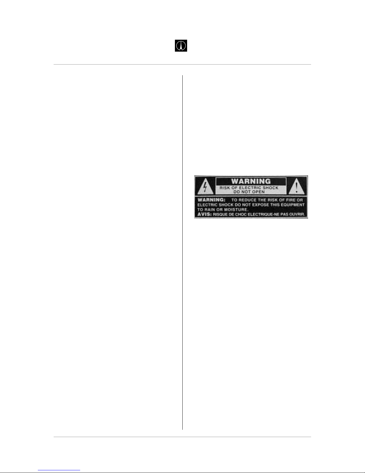
3.1 Safety Instructions
This unit contains voltages that can cause
serious injury or death. Do not operate
with the covers removed.
Improper connection of the equipmentgrounding cable can result in a risk of electric
shock.
Check with a qualified electrician or
serviceman if you are in doubt about your
electrical power or ground connection. The
Vt-747sp is for use with an AC supply as
selected by the AC voltage selector (located
within the AC inlet on the rear of the chassis).
Voltages are 100-120-220-240 VAC +/-5%,
50-60Hz, at 60 watts.
3.2 Grounding Instructions
Always connect the Vt-747sp to a grounded
AC power circuit.
If the unit should malfunction or become
"live", the chassis ground will provide the path
of least resistance for electric current to
reduce the risk of fatal shock.
Page 10 Avalon Vt-747sp Operation Manual
AVALON DESIGN
Safety and
Grounding
Page 11
This product is equipped with an AC
power inlet and must be connected to a
three-wire grounded plug.
The AC power cable must be plugged into an
appropriate outlet that is correctly installed
and grounded in accordance with all local
electrical safety codes and ordinances.
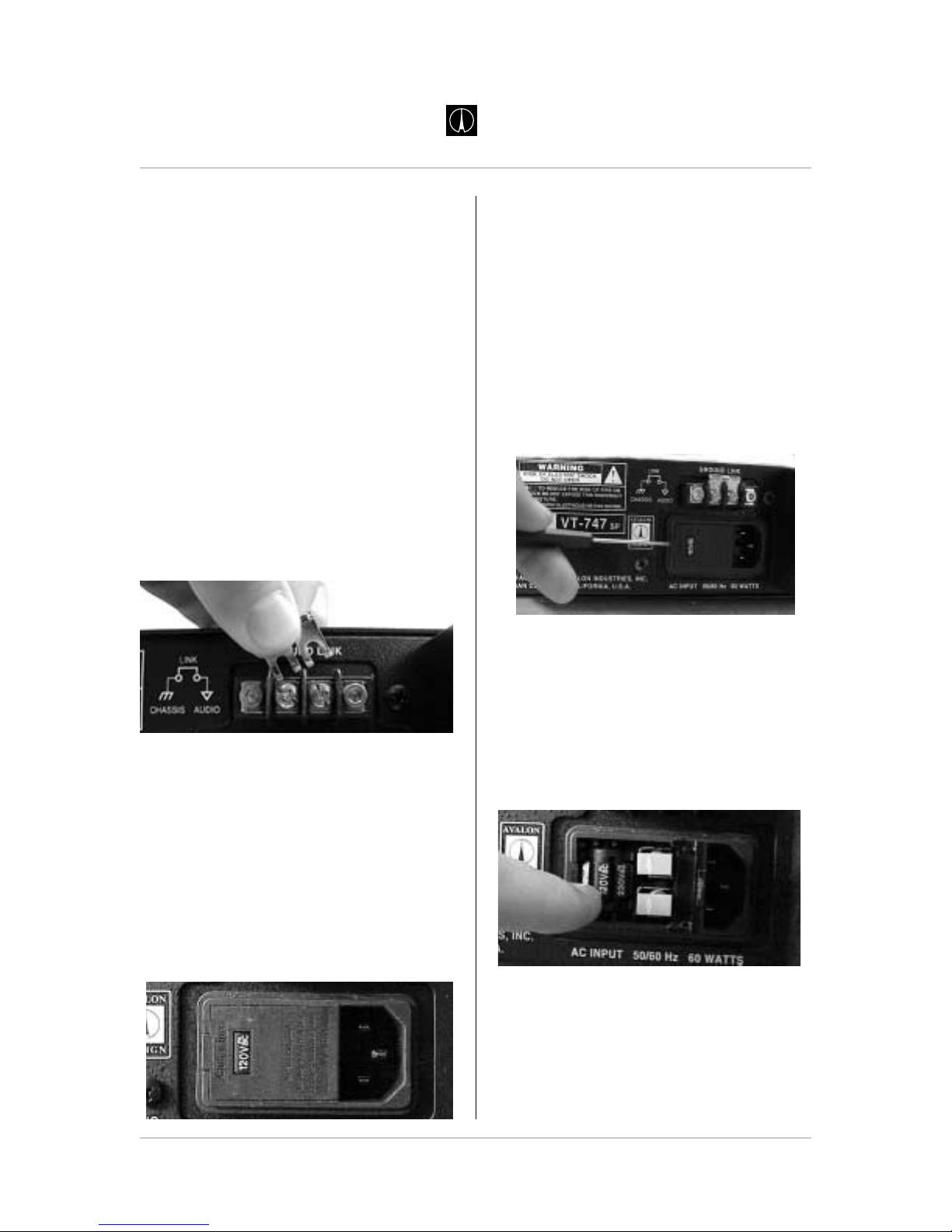
If hum or ground-buzz is induced into the
system, remove the rear-mounted GROUND
LINK. This ground-link isolates the AC
chassis ground from the audio ground. When
the LINK is removed, the AC ground remains
connected to the chassis via the AC inlet
connector and provides a direct path for any
electrical fault or dangerous condition.
Warning! No ground adapter should ever
be used with this unit.
3.3 AC Voltage Selection
Before connecting the Vt-747sp to the AC
supply, check the OPERATING VOLTAGE
located on the rear of the chassis in the
AC inlet connector.
Voltages available are 100-120-220-240VAC
+/-5%, 50-60Hz at 60 watts. (USA uses 120V)
To change the AC voltage for your location:
1. Make sure there is no AC power cable
connected to the AC inlet.
2. Insert a small flat-head screwdriver tip into
the voltage selector cavity. Carefully lift-open
the hinged cover from left to right.
3. Rotate the selector wheel to show the
correct voltage for your location, then push
the wheel firmly into the mounting tabs.
4. Press the voltage selector cover snap-shut,
check correct AC voltage in window.
5. Connect grounded AC power cable.
Page 11
Avalon Vt-747sp Operation Manual
AVALON DESIGN
Safety and
Grounding
AVALON DESIGN
Page 12
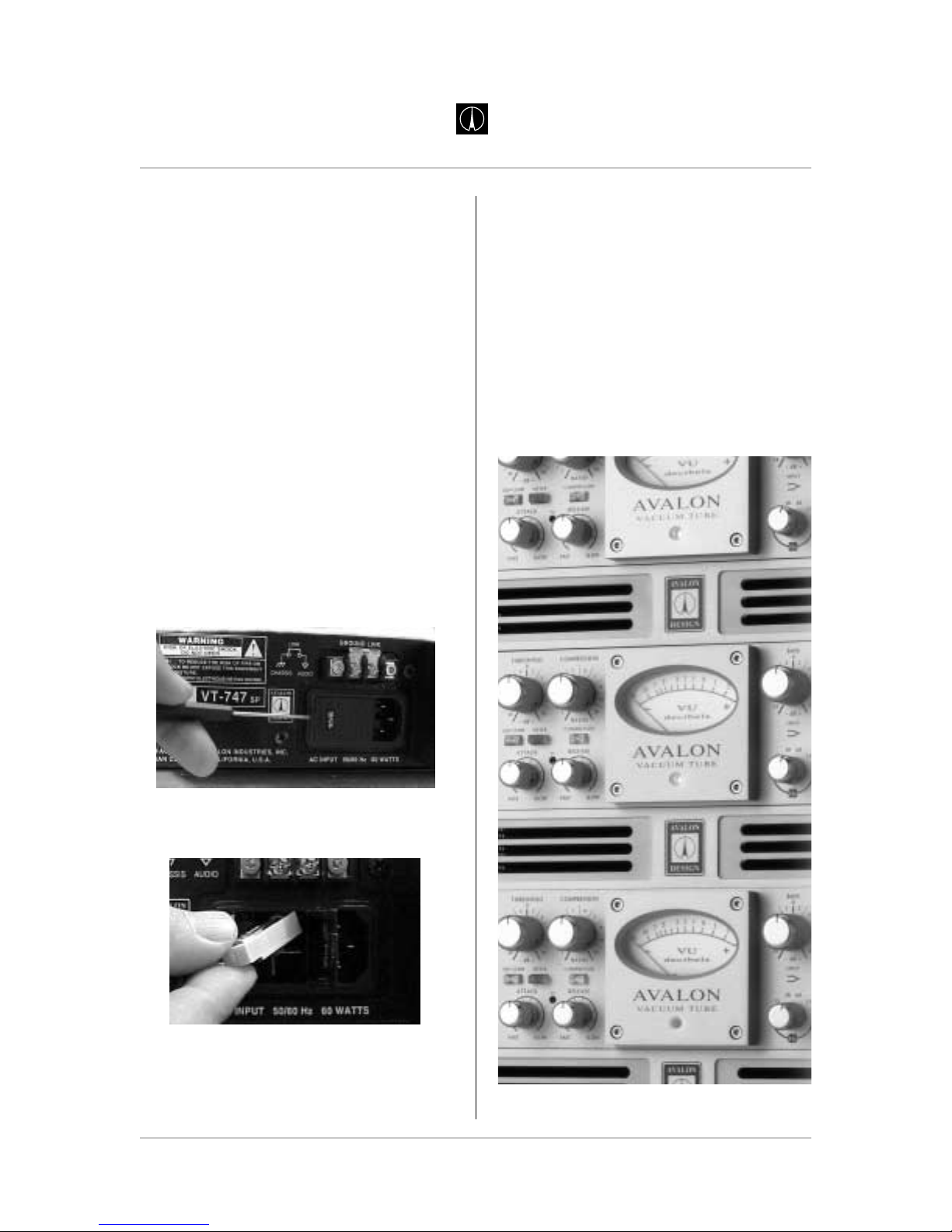
3.4 Fuse Replacement
The fuse on the Vt-747sp is located within the
AC plug assembly on the back of the unit. A fuse
can blow if the AC selection is not selected
properly or if there is a sudden surge of AC to
your Vt-747sp.
Your Vt-747sp uses a 250V, 1 amp slow blow
fuse.
To change the fuse:
1. Make sure there is no AC cable connected
to the AC inlet.
2. Insert a small flat-head screwdriver tip into
the voltage selector cavity. Carefully lift-open
the hinged cover from left to right.
3. Pull fuse casing (labled with an arrow)
straight out.
4. Replace fuse in casing. Insert casing into
casing slot. Close AC voltage selector cover.
3.5 Rack Mounting and Cooling
The Vt-747sp is designed to be mounted in a
standard 19" equipment rack. As vacuum
tubes and Class Acircuitry can generate heat,
it is highly recommended that an additional
rack space above and below the unit be kept
empty to allow for adequate cooling. Avalon
Design has developed 1U ventilation panels
(VP-1) specifically to keep your rack-mounted
gear cool.
Page 12 Avalon Vt-747sp Operation Manual
AVALON DESIGN
Safety and
Grounding
Avalon units with VP-1 vent panels
Page 13

Page 13
Avalon Vt-747sp Operation Manual
AVALON DESIGN
Safety and
Grounding
AVALON DESIGN
Be sure that the ventilation slots (located on
the top and bottom of the unit) are not
obstructed and air is allowed to flow easily
through the chassis. If the unit is not rackmounted, be sure to place supports under the
unit to allow air to pass underneath. Never
leave any obstruction on top of the unit (such
as papers or books) blocking ventilation slots.
Also, be sure that the heat sink mounted on
the rear panel of the chassis has adequate
clearance from the equipment enclosure and
any adjacent equipment. In electronic
equipment, excessive heat is the cause of
most component failures. A little extra
precaution to ensure proper ventilation can
help avoid many premature equipment
breakdowns.
Always use all four front panel-mounting
holes when mounting the Vt-747sp in a rack
enclosure. If not shipped in its original
packing, the Vt-747sp should be transported
in a floating-type shock-mounted flight case.
Although the Vt-747sp is well shielded
against moderate electrical and magnetic
fields, care should be taken to avoid areas
that are in proximity to large motor or power
transformers. Locations near sources of high
RFI (radio frequency interference) such as
computers or digital effects devices should
also be avoided.
Because of the microphonic nature of
vacuum tubes, areas of extreme vibration or
sound levels should also be avoided.
3.6 Turn-on Procedure
The Vt-747sp is designed with a "soft-start"
feature that slowly brings the unit to life when
the unit is powered on. This feature ensures
that there is no strain on the electronic
components when it is activated. It takes
approximately 60 seconds for the unit to run
through the "soft-start" turn-on procedure.
When the Vt-747sp is switched off or during
the "soft-start" turn-on procedure, it is in hard
wire bypass mode and the unit will pass
signal utilizing a hard wire relay but none of
the controls will operate.
Allow the unit to warm up for at least
thirty minutes prior to use. This allows the
components time to come up to temperature
and stabilize before recording begins.
It is recommended that the unit be turned
off during periods of "non-use" greater
than 4 hours.
Page 14

4.0 Operation and Controls
The following chapter describes the details of
your Vt-747sp and how to operate each
function.
INPUT
Continuously variable control trims input level
of signal source. This control will drive the
tubes harder while in tube mode to get more
tube tone into the compressor. In discrete
mode (TSP disengaged) the transistors are
driven harder to achieve more classic
discrete transistor sound. The input has
+36dB of headroom before overload. You can
use this control at minimum and maximum
levels for different sounds and colors.
GAIN +10dB
Boosts the signal by +10dB. This switch
enables more flexibility for another set of
sounds and colors, and for matching low level
sources. (e.g. keyboards, synthesizers, etc.)
TSP (Tube Signal Path)
Illuminated switch IN swaps three (3) tubes
into the audio path from discrete Class A
transistor-based amplifiers.
THRESHOLD
This control sets compressor threshold level.
Continuously variable from -30dB to +20dB.
EQ > COMP
Switches six-band passive equalizer before
(pre) the compressor. This gives flexibility to
achieve different sounds. Putting the EQ
before the compressor will give the signal a
more squashed and narrow sound than if the
EQ follows the compressor.
LF SIDE-CHAIN THRESHOLD
Controls the increase of compression for the
LF specified frequency range. As the
Threshold is turned counter clockwise (made
more negative), the frequency set with the LF
Side-Chain Threshold Hz will be compressed
harder than the compression of the overall
program. (Operates in the reverse of a standard EQ +/- control.)
HF SIDE-CHAIN THRESHOLD
Controls the increase of compression for the
HF specified frequency range. As the
Threshold is turned counter clockwise (made
more negative), the frequency set with the HF
Side-Chain Threshold Hz will be compressed
harder than the compression of the overall
program.
7
6
5
4
3
2
1
Page 14 Avalon Vt-747sp Operation Manual
Operation and
Controls
AVALON DESIGN
1
2 4 5 6 7 8 93 10 12
22 24 2623 25 27 2816
11
18 19
13
2114 15 17 20
Page 15

VU METER (0dB calibration screw)
Recessed screwdriver adjustment for setting
0dB on the VU meter. The VU meter indicates
the amount of gain reduction in dB.
To calibrate the VU meter: Power unit on and
allow 30 minutes before making this adjustment so that components can warm up to
operating temperature. While there is no signal
present, adjust the trim pot so the needle on
the VU meter lines up with zero (“0”).
COMPRESSION RATIO
Sets the compression ratio. Continuously
variable from 1:1 to 20:1.
Note: With opto-compressors, the Threshold
and Compression Ratio are interactive and
are effected by one another.
COMPRESSOR
Switches the compressor in the signal path
with a sealed silver relay. (Hard-wire bypass)
VU METER
Analog VU meter indicates gain reduction.
The VU meter’s needle is speed sensitive for
measuring attack and release of the signal.
EQUALIZER
Switches the six-band passive graphic
equalizer in the signal path with a sealed
silver relay. This EQ is designed for subtle
sweetening and shaping. It is very simple and
easy to use. The frequency turnover, Q and
amplitude ranges have been carefully chosen
for each band to provide extremely smooth
musicality. Pushing the faders up from center
detent will boost and pushing the faders down
will cut.
OUTPUT
Continuously variable output control. This
controls the overall program level of the Vt-747sp.
The Vt-747sp is calibrated so that 0 on the
LED output meters accurately shows +4dBu.
ATTACK
Varies attack time of compressor from 2ms
(FAST) to 200ms (SLOW).
RELEASE
Varies release time of compressor from
100ms (FAST) to 5 seconds (SLOW).
LF SIDE-CHAIN THRESHOLD Hz
Sweep variable peak/dip frequency setting for
Side-Chain parameter. (60Hz to 1kHz)
SIDE-CHAIN
Activates the two-band parametric spectral
Side-Chain controls.
GR (Blue LED)
Fast-acting blue light indicates peak gain
reduction.
HF SIDE-CHAIN THRESHOLD Hz
Peak/dip variable sweep frequency side
chain parameter. (600Hz to 10kHz)
SC LISTEN
To monitor the signal going into through the Side
Chain before it is effected by the compressor .
MAKE-UP GAIN
Variable 0dB to +10dB control to add gain
after compressed signal. (Only acts when the
compressor switch is in.)
21
20
19
18
17
16
15
14
13
12
11
10
9
8
Page 15
Avalon Vt-747sp Operation Manual
Operation and
Controls
AVALON DESIGN
Page 16

LOW-BASS EQUALIZER BAND
Controls low-bass frequency range:
+/-24dB 15Hz shelf
MID-BASS EQUALIZER BAND
Controls mid-bass frequency range:
+/-8dB 125Hz peak/dip
LOW-MID EQUALIZER BAND
Controls low-mid frequencies0
+/-4dB 500Hz peak/dip
MID-RANGE EQUALIZER BAND
Controls mid frequency range:
+/-4dB 2kHz peak/dip
HIGH-MID EQUALIZER BAND
Controls high-mid frequency range:
+/-10dB 5kHz shelf
HIGH-RANGE EQUALIZER BAND
Controls high frequency range:
+/-20dB 32kHz shelf
AC Power Switch
Turns the power on and off. You must allow
approximately 60 seconds from the time you
turn on the power switch for the Vt-747sp to
complete the entire soft start turn-on procedure. For more details on the soft start procedure please refer to Chapter 3.5 Turn-on
Procedure.
28
27
26
25
24
23
22
Page 16 Avalon Vt-747sp Operation Manual
Operation and
Controls
AVALON DESIGN
Vt-747sp production at Avalon
Page 17

4.1 Rear Panel Description
LINE INPUT (Left and Right)
Female XLR-3 connectors. Balanced input for
line level signals to +36dB maximum.
(pin +2 hot)
LINE OUTPUT (Left and Right)
Male XLR-3 connectors. Balanced DC coupled,
capable of +30dB into 600 ohms.
(pin +2 hot)
GROUND LINK
2-terminal barrier strip. Provided to isolate
chassis ground from audio ground. To lift
ground, simply unscrew both phillips-head
screws and remove the metal strip held by the
screws.
AC INPUT & FUSE
Combination IEC socket, voltage selector and
fuse location. AC voltage is factory set as
ordered. To change the factory voltage setting,
refer to the AC Voltage Selection section of this
manual in Chapter 3 (page 11), or contact your
authorized Avalon dealer .
For instructions on changing the fuse, see
Chapter 3.4 Fuse Replacement (page 12).
4.2 Connections
The LINE INPUTS are an electronically
balanced Class Acircuit with a nominal 20k ohm
input impedance. (Can be used unbalanced by
shorting pin 3 to ground on the cable connector.)
The connectors are female XLR-3.
The OUTPUTS are a low impedance
electronically balanced circuit which terminates
to a male XLR-3 connector. (Can be used
unbalanced by shorting pin 3 to ground on the
cable connector.)
All XLR connectors are wired:
Pin 1 ground
Pin 2 high (+)
Pin 3 low (-)
Input Impedance: 20k Ohm
Output Impedance: 600Ohm
4.3 Unbalanced Operation
The Vt-747spcan also be used in unbalanced
mode by grounding pin 3 on the cable input
and output pins.
4
3
2
1
Page 17
Avalon Vt-747sp Operation Manual
Operation and
Controls
AVALON DESIGN
1
2
3
4
AVALON DESIGN
Page 18

4.4 Using the Vt-747sp
The opto-compressor of the Vt-747sp has
the standard features of a typical outboard
compressor plus a few other unique features
like no other compressor. Basic operation is
as follows:
1. Engage the COMPRESSOR push-button.
This will insert the compressor into the signal
chain.
2. Set ATTACK to FAST.
3. Set RELEASE to FAST.
4. Set COMPRESSION to 20:1(fully clockwise)
5. Set THRESHOLD to –30dB (fully counter
clockwise)
6. Test compression by introducing signal.
Needle should move rapidly for any substantial input signal. Turn up the INPUT GAIN if
needle is not moving.
8. Fine tune controls for desired effect.
4.5 Six Band Passive Equalizer
The six band graphic equalizer is extremely
smooth and musical. The six frequency
bands and corresponding Q settings have
been carefully chosen to provide the most
natural harmonic balance and lowest phase
change while offering simple and effective
tone control.
The following is a description of the six frequency bands.
From Low to High (left to right)
1. +/- 24dB 15Hz shelf response
2. +/- 8dB 125Hz selected Q response
3. +/- 4dB 500Hz selected Q response
4. +/- 4dB 2kHz selected Q response
5. +/- 10dB 5kHz shelf response
6. +/- 20dB 32kHz shelf response
4.6 Using the Equalizer
The equalizer section of the Vt-747sp has
been designed to be easy to use.
Engage EQ push-button (illuminates "IN") to
insert the EQ in the signal path.
All six faders have a center detent. When all
faders are set to center detent the EQ is
completely flat.
Pushing a fader up from the center detent
boosts the corresponding frequency band
and pushing a fader down from the center
detent cuts the corresponding frequency
band.
Because of the passive design, the equalizer
on the Vt-747sp is smooth and musical. It can
be used to subtly shape and color while still
keeping the signal musically balanced
(program equalizer.)
Page 18 Avalon Vt-747sp Operation Manual
Operation and
Controls
AVALON DESIGN
Page 19

Page 19
Avalon Vt-747sp Operation Manual
Applications
AVALON DESIGN
4.7 Using the Side-chain
Inserting an equalizer into a compressor’s
gain reduction control path is commonly
known as side-chaining. This effect allows
for spectral control of the compression at the
specified frequencies. The most frequent
application of this technique is known as
de-essing. De-essing is the removal of
excessively pronounced "S" sounds from
vocal recordings. You can de-ess with the
Vt-747sp and any other frequencies where
you need a little more compression than the
overall program.
To insert the two-band spectral EQ into the
Side Chain:
1. Set the compressor to full compression to
begin. (described in previous section)
2. Engage the SIDE-CHAIN switch
3. Set the HF and LF Threshold controls to
-15dB (fully counterclockwise)
4. Press in the SC LISTEN to monitor
5. Sweep the LF and HF frequency controls
to find the desired signals to send into the
Side-Chain.
6. Depress the SC LISTEN switch (non-illuminated)
so that the signal you were emphasizing with
the SC LISTEN is now routed into the gain
control section of the compressor.
5.0 Applications
The first thing to remember is that there are
no specific rules. The Vt-747sp was
designed to be extremely flexible and filled
with endless colors, textures and tones.
TRUST YOUR EARS!
5.1.0 Typical Set-ups
The following setup diagrams are a few
typical ways (not the only ways) to insert the
Vt-747sp in the audio chain during a
recording project. Much of the power in the
Vt-747sp lies within its flexibility. You can use
the Vt-747sp in every stage of the recording
or mixdown process:
Figure 5.1.1 - Recording to direct to Digital
Audio Workstation (DAW) or tape machine.
Note that the Vt-747sp is a line level unit only.
It does not have microphone preamplifiers
(mic pre’s). You must use mic pre’s Such as
the two-channel Avalon AD2022, before
inserting the Vt-747sp during recording. The
Vt-747sp works wonderfully with keyboards,
drum machines, synthesizers and other line
level inputs enabling you to completely
bypass the mixing console and go directly to
your DAW or tape machine.
Figure 5.1.2 - Mixdown Stereo Buss - Main
right/left Insert or across the entire stereo mix.
Figure 5.1.3 - Mixdown and/or Mastering
on DAW - Across a stereo submix or the
entire mixed stereo signal
Figure 5.1.4 - Mastering Tape Based - Main
Right and Left Outputs
Page 20
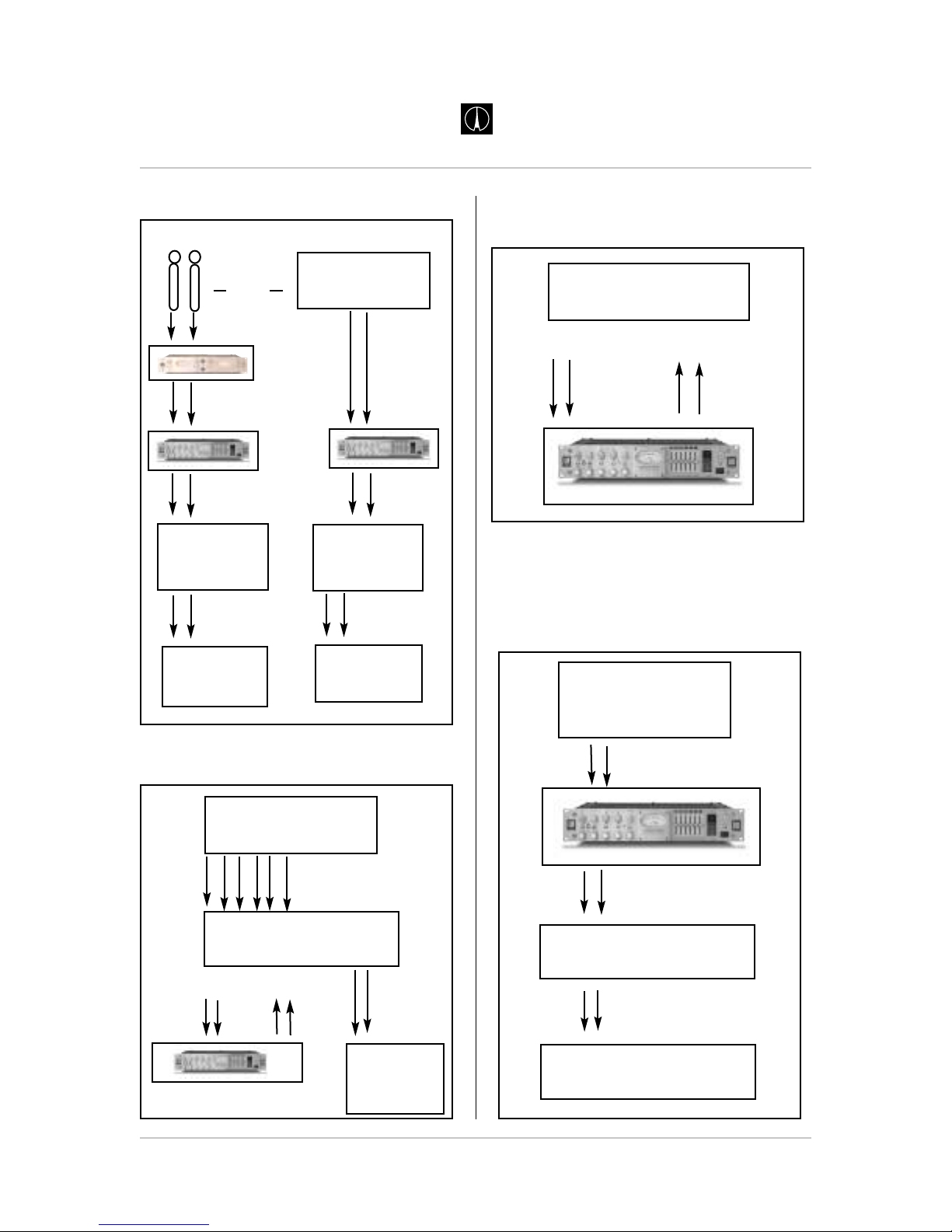
Figure 5.1.1 - Recording
Figure 5.1.2 - Stereo Mixdown (Buss)
Figure 5.1.3 - Mixdown or Mastering Using
DAW
Figure 5.1.4 - Mastering Tape Based
Page 20 Avalon Vt-747sp Operation Manual
Applications
AVALON DESIGN
Keyboard, synth,
drum machine, etc.
OR
Stereo Mics
Vt-747sp
Inputs
Outputs
Inputs
outputs
Inputs
Outputs
Outputs
Tape Machine
or
DAW
Tape Machine
or
DAW
Inputs
Outputs
Inputs
Outputs
Mixing Console
for Monitoring
Inputs
Mixing Console
for Monitoring
Inputs
Analog or Digital
Tape Machine
Mixing Console
Multiple Outputs
Multiple Line Inputs
Stereo Submix
or Main Insert
Inputs
DAT
or
CD Burner
Inputs
Vt-747sp
DAW
Rt and Lft Stereo
Submix Outputs
Inputs - Record
Two New Tracks
Inputs
Outputs
Stereo Mix
on DAT, CD, or
Tape Mach
Final Media - DAT or CD
Outputs
Inputs
Inputs
Outputs
Vt-747SP
Monitoring System
Outputs
Inputs
AD2022
(mic pre)
2 new inputs
or buss inputs
Main Outputs
or Tape Output
Page 21

5.2.0 Application Settings
The following are a few example settings for
the Vt-747sp to be used as starting points for
specific applications. You will most likely need
to adjust the settings given here for your
recordings because of the many variables
which depend on a recorded sound. Variables
such as microphone choice, microphone
placement, recording room, recording media,
mixing console, the musician, etc., can
greatly alter and change the sound of a
recording. Simply stated, trust your ears.
Note: The output controls the signal level to
the next piece of equipment in the audio
chain. The output control is designed to be
sonically invisible. This means that you can
set the output level based on what signal
level you want coming out of the Vt-747sp
and you will not color the signal by turning this
control up or down. Therefore, the output
level is not included in the example
settings.
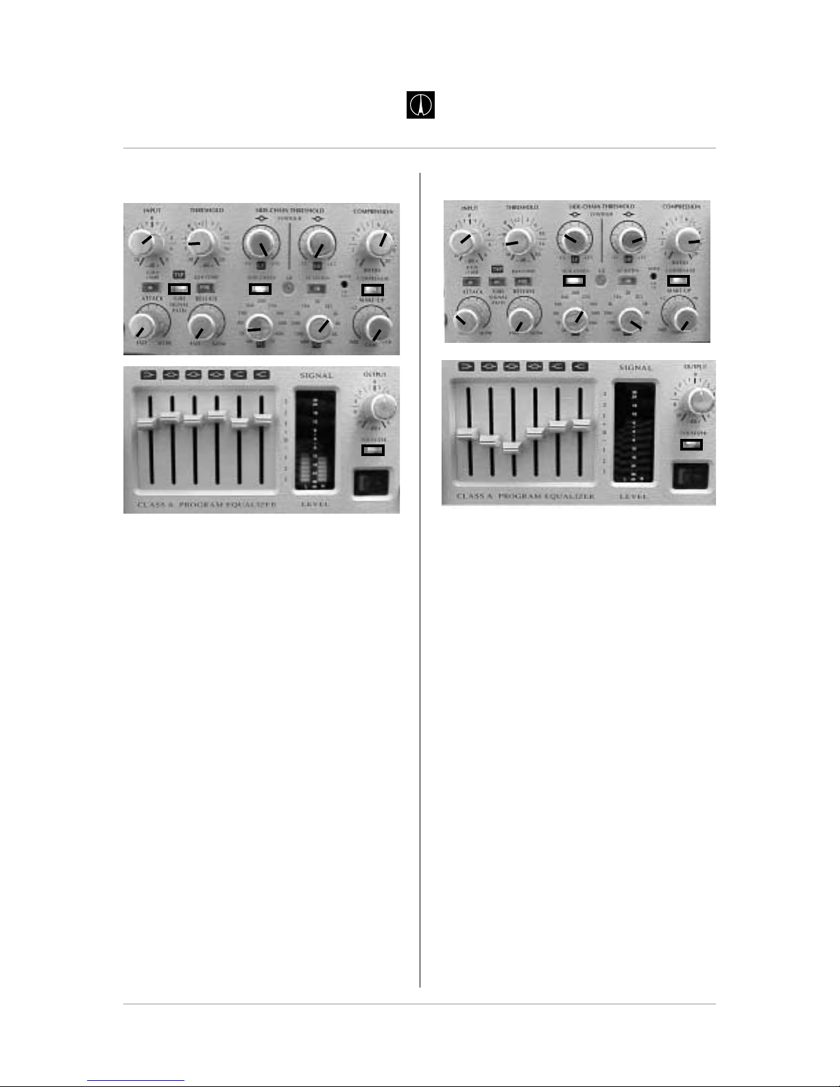
5.2.1 Stereo Buss for Mixdown
Input: +3
Gain: Out
TSP: Out
Compressor: In
EQ->Comp: Out
Compression Ratio: 5:1
Compression Threshold: -15
Attack: 11 o’clock
Release: Fast
Make-up: +1 (10 o’clock)
Side-Chain: Out
Side-Chain LF Threshold: bypassed
Side-Chain LF Frequency: bypassed
Side-Chain HF Threshold: bypassed
Side-Chain HF Frequency: bypassed
Equalizer: In
EQ Faders from left (1) to right (6):
1. +2
2. +1
3. +1
4. +1
5. +1
6. +2
Page 21
Avalon Vt-747sp Operation Manual
Applications
AVALON DESIGN
Page 22

5.2.2 Stereo Buss & Vocal De-ess
Input: +3
Gain: Out
TSP: In
Compressor: In
EQ->Comp: In
Compression Ratio: 5:1
Compression Threshold: -12
Attack: Fast
Release: Fast
Make-up: +1 (10 o’clock)
Side-Chain: In
Side-Chain LF Threshold: +15
Side-Chain LF Frequency: 200Hz
Side-Chain HF Threshold: -15
Side-Chain HF Frequency: 7kHz
Equalizer: In
EQ Faders from left (1) to right (6):
1. +1
2. +1
3. +0.5
4. +0.5
5. +1
6. +1
5.2.3 De-ess on Vocals
Input: +2
High Gain: Out
TSP: In
Compressor: In
EQ->Comp: In
Compression Ratio: 20:1
Compression Threshold: -20
Attack: Fast
Release: Fast
Make-up: +2
Side-Chain: In
Side-Chain LF Threshold: +15
Side-Chain LF Frequency: 200Hz
Side-Chain HF Threshold: -15
Side-Chain HF Frequency: 7kHz
Equalizer: In
EQ Faders from left (1) to right (6):
1. +1
2. 0
3. 0
4. +0.5
5. +0.5
6. +0.5
Page 22 Avalon Vt-747sp Operation Manual
Applications
AVALON DESIGN
Page 23

5.2.4 Stereo Keyboards
Input: +3
High Gain: Out
TSP: In
Compressor: In
EQ->Comp: Out
Compression Ratio: 6:1
Compression Threshold: -17
Attack: 11 O’clock
Release: Fast
Make-up: +2
Side-Chain: Out
Side-Chain LF Threshold: bypassed
Side-Chain LF Frequency: bypassed
Side-Chain HF Threshold: bypassed
Side-Chain HF Frequency: bypassed
Equalizer: In
EQ Faders from left (1) to right (6):
1. 0
2. +1
3. +1
4. +2
5. +2
6. +1
5.2.5 Extreme Compression
Input: 0 - Unity
Gain: Out
TSP: In
Compressor: In
EQ->Comp: In
Compression Ratio: 20:1
Compression Threshold: -20
Attack: Fast
Release: 12 O’clock
Make-up: +10
Side-Chain: Out
Side-Chain LF Threshold: bypassed
Side-Chain LF Frequency: bypassed
Side-Chain HF Threshold: bypassed
Side-Chain HF Frequency:bypassed
Equalizer: In
EQ Faders from left (1) to right (6):
1. +3
2. +2
3. +1
4. +1
5. +2
6. +2
Page 23
Avalon Vt-747sp Operation Manual
Applications
AVALON DESIGN
Page 24
5.2.6 Acoustic Piano
Input: +2
Gain: Out
TSP: In
Compressor: In
EQ->Comp: Out
Compression Ratio: 6:1
Compression Threshold: -12
Attack: Fast
Release: Fast
Make-up: 0
Side-Chain: In
Side-Chain LF Threshold: +15
Side-Chain LF Frequency: 70 Hz
Side-Chain HF Threshold: -15
Side-Chain HF Frequency: 3kHz
Equalizer: In
EQ Faders from left (1) to right (6):
1. +1
2. +2
3. +1
4. +2
5. +1
6. +1.5
5.2.7 Acoustic Guitar
Input: +3
Gain: Out
TSP: Out
Compressor: In
EQ->Comp: Out
Compression Ratio: 9:1
Compression Threshold: -15
Attack: 10 O’clock
Release: Fast
Make-up: 0
Side-Chain: In
Side-Chain LF Threshold: 10 O’clock
Side-Chain LF Frequency: 250 Hz
Side-Chain HF Threshold: 3 O’clock
Side-Chain HF Frequency: 7 kHz
Equalizer: In
EQ Faders from left (1) to right (6):
1. 0
2. -0.5
3. -1
4. 0
5. +0.5
6. +0.5
Page 24 Avalon Vt-747sp Operation Manual
Applications
AVALON DESIGN
Page 25

Page 25
Avalon Vt-747sp Operation Manual
Compression and
EQ Primers
AVALON DESIGN
5.2.8 Drum Overheads
Input: +4
Gain: Out
TSP: In
Compressor: In
EQ->Comp: Out
Compression Ratio: 4:1
Compression Threshold:-17
Attack: Fast
Release: Fast
Make-up: +5
Side-Chain: Out
Side-Chain LF Threshold: bypassed
Side-Chain LF Frequency: bypassed
Side-Chain HF Threshold: bypassed
Side-Chain HF Frequency: bypassed
Equalizer: In
EQ Faders from left (1) to right (6):
1. 0
2. +2
3. +1
4. +0.5
5. +1
6. +2
6.0 Compression Primer
A compressor is one of the most widely used
signal processors in the recording studio.
Compressors are used during the recording
process as well as during mixdown and
mastering. During the recording process
compressors are used to control the dynamic
range or volume of a signal. For example,
a singer may vary his volume level from a
whisper to a scream during a particular song.
A compressor will control the volume of the
vocal so that the volume is consistent whether
the singer is whispering or screaming. During
mixdown compressors are used to "tighten
up" the tracks so that nothing pops out of the
mix uncontrollably. During the mastering
process compressors are used very slightly to
tighten up the entire mix and can give the mix
a bigger sound.
The way a compressor works is like an
automatic fader. When the input signal
exceeds a predetermined level called the
threshold, the gain is reduced by the
compressor and the signal is attenuated. By
attenuating the louder signal levels, you are in
fact, reducing the program’s overall dynamic
range. Because the range between the
loudest and softest signal is "compressed" by
increasing the signal’s overall gain, the
average level will be greater. Thus the signal
will be perceived as being louder than it
otherwise would be.
Compression is measured by the ratio of the
change in output level (in dB) to the change in
input level, called the compression ratio. If a
compressor is set to 8:1 compression then an
8 dB increase in the input level will result in a
1dB increase in the output level.
Page 26

Compression Variables Defined
Compressors are controlled by four main
functions: Threshold, Ratio, Attack and
Release.
Threshold: Defines the level where
compression begins. If the sound level coming
into the input is below the threshold, the
compressor passes the signal with no change.
When a louder signal rises above the
threshold, the compressor starts working,
automatically reducing the output gain by the
amount set with the ratio control.
Ratio: The ratio control is the amount of
volume reduction relative to the original signal
level. A 1:1 (one to one) ratio is the lowest
compression ratio. This means that the volume
that goes into the compressor is exactly the
same as the volume that comes out. A2:1 ratio
means that the compressor will only allow the
output level to rise 1dB for every 2dB that the
input is over the threshold. This way the
compressor allows the signal to be louder than
the threshold, but only by half as much. This is
typical moderate compression. A 4:1 ratio
means that if the input signal is 4dB over the
threshold, the compressor only allows an
output 1dB over the threshold.
Attack: The very beginning of a sound is
usually the loudest and most difficult to record
smoothly (for example, vocals, slap bass,
guitar, etc.). In many cases you want to let
these initial transients pass through before
pulling down the gain, other times you want the
compression to start right away. T o help make
adjustments to this specific event, the attack
control adjusts the length of time it takes for the
compression to begin.
Release: Once the signal falls below the
threshold, the Release control determines how
quickly the compressor "lets go" of the volume
control and lets the level rise back to unity
gain. Just as the Attack control sets the volume
of the start of a sound, the Release control sets
the volume of the end of a sound. The release
can be used creatively to make sounds cut-off
sharply or sustain longer .
Compressors usually have built-in metering to
allow monitoring of the amount of gain
reduction taking place. The meter usually sits
at 0 VU when the input signal is below the
threshold and falls to the left to indicate the
number of decibels of gain reduction. Also the
actual speed of the moving needle indicates
the attack and release speeds.
Page 26 Avalon Vt-747sp Operation Manual
Compression and
EQ Primers
AVALON DESIGN
Time
Compression Ratio = 5:1
Threshold = +5 dB
dB
+5dB
Graphic description of compression
Page 27

6.1 Equalization Primer
An equalizer is a group of tone controls that
allow adjustment to the frequency range of an
incoming signal using a number of separate
frequency bands. A graphic equalizer
consists of a number of pre-selected
frequency bands, boost/cut control, and a
pre-set bandwidth or “Q” control for each
frequency band. Each fader on a graphic
equalizer corresponds to a specific frequency
range to either cut or boost. The bandwidth
of the frequency range is preselected. The
mid bands are typically peak/dip while the
end bands are typically shelving filters.
A six-band graphic (program) equalizer as
found in the Vt-747sp consists of six
frequency selection controls: Low-bass, Midbass, Low-mid, Mid, High-mid, and High.
Each frequency band has carefully selected
cut/boost, frequency range, and Q
parameters that are useful and effective to
shape and sweeten the signal. The Low
Bass, High Mid and High bands are shelving
filters while the Mid-bass, Low-Mid, and Mid
bands are peak/dip filters. For details on the
Vt-747sp graphic EQ parameters see
Chapter 3, Operation and Controls.
7.0 FAQs
The following are answers to Frequently
Asked Q
uestions about the Vt-747sp:
Q: Can I use the Vt-747sp as an insert for
compression and EQ?
A: Yes. the Vt-747sp is perfect as an insert for
a recorded stereo signal such as keyboards,
acoustic piano, drum overheads, acoustic
guitar, etc.
Q: What’s the main difference between the
Vt-747sp’s compressor and Avalon’s
AD2044 compressor?
A: The Vt-747sp is a dedicated stereo
compressor that is loaded with many different
tones and color. The Vt-747sp has vacuum
tubes, six-band program equalizer and built in
spectral control. The AD2044 is an ultra-high
performance pure Class A 100% discrete
traditional compressor. It features extreme
dynamic range, ultimate low noise and
completely transparent compression, great
for mastering, tracking and mixing.
Q: How often will I need to change the
tubes?
A: The vacuum tubes on the Vt-747sp are
military spec tubes rated for over 5,000 hours.
Avalon recommends changing the tubes
approximately every 2 years or so on a unit
that is used regularly. Avalon recommends
that you replace tubes with exact make and
model of the tubes that Avalon specifies. You
may purchase a spare set of tubes for your
Vt-747sp directly from Avalon.
Q: Can I damage the Vt-747sp by turning
the preamp gain up too high?
A: No. The Vt-747sp has enormous
headroom. Crank it up and check it out.
Page 27
Avalon Vt-747sp Operation Manual
FAQs
AVALON DESIGN
Page 28

Q: Why does Avalon use opto cells?
A: Avalon uses opto-cell compression
because they are the most musical of all
ccntrol elements.
Q: Can I do mastering with a Vt-747sp?
A: Yes. Since the Vt-747sp is a dedicated
stereo unit it is a great tool for mastering. The
noise floor is low enough for mastering and
the built-in EQ and side chain are perfect for
gentle shaping and sweetening.
Q: Is the Vt-747sp durable enough for the
road?
A: Yes. the Vt-747sp as well as all Avalon
equipment is literally built like a tank. Steel
chassis, metal faceplate, metal knobs, all
circuit boards are fixed with stainless steel
hardware and more.
Q: Should I power down the Vt-747sp ?
A: The Vt-747sp is equipped with a “soft-start”
procedure that slowly brings the unit to life
without damaging the tubes. Avalon
recommends that you turn the unit off if not
being used for more than 4 hours. This
procedure will also save on your electric bills.
Q: Will the Vt-747sp continue to work
when I travel to different countries?
A: Yes. The power supply on the Vt-747sp
has selectable voltages: 100V, 120V, 220V,
and 240V. It is very easy to change the
voltage. See chapter 3.
Q: Why is the High-Mid Band on the Vt747sp shelving and not peak/dip like the
other Mid Bands?
A: Having two shelving bands on the high end
of the equalizer gives more flexibility and
musicality. If you want to utilize the High-Mid
Band as a peak/dip then simply cut (turn
down) the High Frequency band to bring
down the ultra high end, giving you more
creative possibilities.
Q: Why does the needle in the VU meter
sometimes drift to the left of 0dB after the
Vt-747sp warms up?
A: As the unit warms up, after approximately
30 minutes, the resistance of the meter coil is
increased with heat and the needle then
settles into its operating 0dB position. If
inadequate cooling is provided, the operating
emperature will be too high. (just like the old
LA2A’s). To calibrate the VU meter to 0dB see
page 32.
Q: Will the Vt-747sp work with unbalanced
inputs on my recording device?
A: Yes. You need to make sure that the
cables you are using are wired the same (pin
2 hot). You can get a cable that has XLR on
one side and RCA or 1/4” on the other. This
will work fine for unbalanced systems. Keep
the cables 20 ft in length or less for best sonic
performance.
Q: Can I use the Vt-747sp with a recording
device that is designed for -10dB operation?
A: Yes. The Vt-747sp will work however the
output signal from the Vt-747sp may be too
hot. Adjust the output control on the Vt-747sp
to match the input to the -10dB device. If you
have a choice, always run at +4dB.
Q: Can I use different types of tubes in the
Vt-747sp to get different or better sounds?
A: Avalon has selected the tubes in your Vt747sp for optimal sonic performance. Avalon
does not recommend experimenting with
different types of tubes because they may
cause extreme damage to the Vt-747sp.
Page 28 Avalon Vt-747sp Operation Manual
FAQs
AVALON DESIGN
Page 29

Q: Why does the Vt-747sp have a six-band
graphic EQ?
A: The Vt-747sp’s graphic EQ is designed to
be very simple to operate and musical. It is
intended to enhance the program material for
sonic retouching and eliminates the need to
patch and addtional EQ if only minor
adjustments are required.
Q: What are the advantages of using the
Vt-747sp with my digital recording system?
A. The Vt-747sp breaths life into digital
recordings. It will add air to the top, enhance
the space in the lower mid range and solidify
the bottom end. This process is very effective
if used with high quality A-D and D-Aconverters. Even if your converters are not of the
highest quality it will still enhance your recordings.
Q: Will the Vt-747sp help to warm up the
signal going to a digital recorder?
A: Yes. The Vt-747sp will give the signal a
richer warmer sound. The bottom end will open
up and your recorded music will sound bigger.
It works wonderfully for synths, drum
machines, and keyboards that would
otherwise sound thin and lifeless.
Q: Can I use the SIDE CHAIN LISTEN function as a parametric EQ?
A: Yes. Press in the SIDE CHAIN LISTEN
button and use the Threshold controls as
cut/boost and the two frequency selectors to
select the frequencies of interest. Note that
the Threshold controls will act in the opposite
direction. (ie. clockwise will cut and counter
clockwise will boost selected frequency.)
Q: What is the difference between the
Vt-737sp and the Vt-747sp?
A: The Vt-737sp is a mono Mic, Line, and
Instrument level preamplifier with compressor
and parametric equalizer. It is great for
recording one channel at a time and for
mixdown on the most important channel.
The Vt-747sp is a dedicated stereo line level
compressor and graphic equalizer. It has no
microphone preamplifier. The Vt-747sp is
great for stereo keyboards, synthesizers, drum
machines, stereo submix or mix buss
applications and mastering.
Page 29
Avalon Vt-747sp Operation Manual
FAQs
AVALON DESIGN
Page 30

8.0 Trouble Shooting
If you experience any problems with your
Vt-747sp, please make sure to first isolate the
problem to your Vt-747sp. In many cases the
problem can be a bad cable or another piece
of equipment in the signal path.
It is easiest to isolate the problem by removing
as many pieces of extraneous gear in the
signal path as possible. If you believe that
your Vt-747sp has a problem, please set up
the following test system:
1. Plug your input source (keyboard, synthesizer
or line input) into Vt-747sp; make sure to check
your cables.
2. Connect the output of Vt-747spdirectly to your
powered speakers or monitor system. Use the
OUTPUT control on the Vt-747sp to adjust the
volume.
Once you have isolated the problem to the
Vt-747sp please check the following list for
suggested solutions.
Page 30 Avalon Vt-747sp Operation Manual
Trouble Shooting
AVALON DESIGN
Problem
No Power
No Power
Lights dim /
no sound
No sound
Hum or buzzing
noise
Distorted sound
Distorted sound
Cause
Power cable on back of chassis not
securely plugged in
Fuse blown due to power surge or
improper AC voltage setting
Improper AC voltage setting
Bad cable
ground loop
Vt-747sp is overheating
Input source overloading
Solution
Plug in power cable
Replace fuse (page 12) and check AC
voltage setting (page 11)
Check AC voltage setting (page 11)
Check cables
Check cable wiring and grounding, lift
ground on Vt-747sp (page 10)
Make sure Vt-747sp has adequate
cooling and ventilation (page 12)
Try a different input source, reduce
input level control
Vt-747sp Trouble Shooting Table
Page 31

Tube Related Symptoms
The following list are symptoms of a failing
vacuum tube. If you are experiencing these
symptoms please call your local dealer or
the Avalon factory at 949-492-2000.
1. Background noise (a crackling or sizzling
sound)
2. Ringing noise
3. Low output volume
4. Distorted sound
Other problems
Please call your nearest dealer or the Avalon
factory at 949-492-2000 if you have any
technical questions or are experiencing
problems not listed in our Trouble Shooting
Table.
Page 31
Avalon Vt-747sp Operation Manual
Trouble Shooting
AVALON DESIGN
Page 32

9.0 Service and
Contact Information
Maintenance and Tube Life
Because of the exceptional build quality of the
Vt-747sp, the unit will perform for many years
to come. Like any musical instrument, it
needs care and maintenance to keep it in top
shape.
Vacuum Tube Replacement
For peak performance, Avalon Design
recommends changing these tubes every
5000 hours of run time. Changing the tubes
every two years is recommended assuming
use of 8 hours per day, 7 days per week. A
matched set of replacement tubes can be
purchased directly from your local dealer or
Avalon. Avalon only recommends Sovtek
6922 vacuum tubes for your Vt-747sp.
Replacement of tubes should be performed
by an authorized Avalon technician.
Meter Calibration and Alignment
The VU meter can be easily adjusted to 0 VU
when no signal is present. To adjust the VU
meter to zero:
1. Turn the unit on
2. Let unit warm up for at least 30 minutes
3. Unplug all inputs
4. From the front of the unit use a small flat
head screwdriver to turn the recessed trim pot
so that the needle reads zero.
External Cleaning
The Vt-747sp can be cleaned using an
ordinary mild house cleaner such as 409 or
Windex. Do not use abrasive cleaners or
petroleum-based solvents. Doing so could
cause damage to the finish.
Contact Information
Avalon Design
PO Box 5976
San Clemente, CA 92673
Tel: 949-492-2000
Fax: 949-492-4284
Email: avalon@avalondesign.com
Website: www.avalondesign.com
Page 32 Avalon Vt-747sp Operation Manual
Service Information
AVALON DESIGN
Page 33

10.0 Technical Information
Your Vt-747sp is built to withstand many
years of high performance music making. If
you experience any malfunctions or
problems, please contact the dealer where
your unit was purchased. If your Vt-747sp
has outlasted your dealer, please contact
Avalon directly.
Specifications
Circuit Topology: Three dual triode vacuum
tubes, plus high-voltage discrete Class A
Input Gain Range: Balanced, Class A, 20k
ohms, +6dB with high gain switch in
Maximum input level: +36 dB balanced XLR
Maximum output level: +30dB balanced
XLR 600 ohms, DC coupled, Pin 2 hot
Output gain range: Output trim gain
-45dB to +10dB
Noise 20-20kHz unweighted: -92dBu
Distortion (THD, IMD) @ 1kHz: 0.5%
Bandwidth (-3dB): 1 to 200kHz
Frequency Response: 10 to 40kHz +/-0.2dB
VU meter and gain reduction: 0VU=+4dBu
and gain reduction to -20dB.
Output meter: Twin 20 segment LED VU
meters with -27dB to +30dB range
Compressor type: optical passive attenuator
Make-up gain: Variable 0dB to +10dB stereo
tracking
Compression ratio: Variable 1:1 to 20:1
Threshold: Variable -30dB to +20dB
Attack: Variable 2mS to 200mS
Release: Variable 100mS to 5 seconds
Side-chain spectral contour: Variable
threshold -15dB to +15dB, frequency 70Hz to
9kHz
Equalizer type: Discrete Class A, passive
design optimized for full-range program
material
Frequency bands (6):
1. LF +/-24dB 15Hz shelf response
2. MF1 +/-8dB 125Hz selected Q response
3. MF2 +/-4dB 500Hz selected Q response
4. MF3 +/-4dB 2kHz selected Q response
5. MF4 +/-10dB 5kHz selected shelf
6. MF5 +/-20dB 32kHz shelf response
AC power: Internal toroidal 100v to 240v, 5060Hz selectable, 60 watts maximum,
enclosed in separate steel chassis
Dimensions: 19 x 12 x 3.5 inches
482 x 305 x 89 mm
Weight: 22 lbs. (10 kg)
Dimensions - shipping carton:
21 x 18 x 8 inches
533 x 457 x 203 mm
Weight packed: 26 lbs. ( 11.8 kg)
Page 33
Avalon Vt-747sp Operation Manual
Technical
Information
AVALON DESIGN
Page 34
Page 34 Avalon Vt-747sp Operation Manual
Technical
Information
AVALON DESIGN
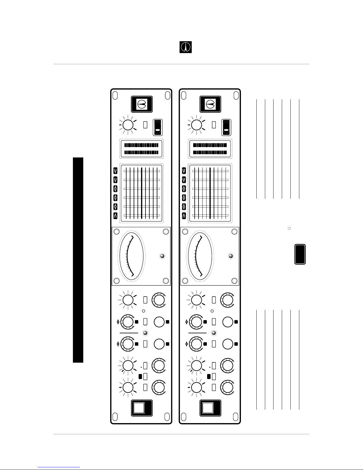
VT-747SP RECALL SETTINGS
Class A Vacuum Tube
STEREO SPECTRAL OPTO-COMPRESSOR
VT-747SP
Avalon Design is a division of Avalon Industries, Inc. 2001
c
TSP
TWIN SIGNAL PATH
20
10
3
2
AVALON
VACUUM TUBE
-
7
5
3
1
0
1
2
d
e
c
i
b
e
l
s
V
U
+
IN IN IN IN INININ
HF
v
747
sp
t
-
dB+
-15 +15 -15 +15
0dB
+2 +6
+10
SIDE-CHAIN THRESHOLD
CONTOUR
GR
SC LISTENSIDE-CHAIN
CAL
GR
GAIN
+10dB
60
100
80
160 250
300
400
1k
Hz
70 600
200
600
1k
800
1k6 2k5
3k
4k
10k
Hz
700 6k
2k
LF
TSP
EQ COMP
INPUT
0
20 8
32
46
610
11
FAST SLOW
ATTACK
TUBE
SIGNAL
PATH
FAST SLOW
RELEASE
GAIN
MAKE-UP
COMPRESSOR
METER
RATIO
COMPRESSION
120
47
83
102
65
-
dB+
THRESHOLD
20 20
0
6
10
-
10
1615
3+2
DESIGN
AVALON
0
123
321
+
-
CLASS A PROGRAM EQUALIZER LEVEL
SIGNAL
-
dB+
OUTPUT
0
20 6
22
34
48
11
EQUALIZER
R
dB
L
30
0
24
18
12
+
-
12
6
6
182430
10.1 Vt-747sp Recall Sheet
Page 35

Page 35
Avalon Vt-747sp Operation Manual
Technical
Information
AVALON DESIGNAVALON DESIGN
BALANCED
20K OHM +36dB
OUTPUT
LEFT
BALANCED
600 OHM +30dB
BALANCED
CLASS A
INPUT AMP
DISCRETE
CLASS A
AMPLIFIER
VU
OUTPUT
LEVEL
INPUT
LEVEL
BALANCED
CLASS A
OUTPUT
DISCRETE
CLASS A
AMPLIFIER
DISCRETE
CLASS A
AMPLIFIER
200v
V2
OUTPUT
LINE AMP
+6dB
V1-A
OPTO
BUFFER
METER
LEFT
SOFT
START
POWER
SUPPLY
+200v
+48v
+34v
-
34v
+18v
-
18v
+12v
+6v3
AC
INPUT
SELECTOR
100-240V
AUDIO
GROUND
CHASSIS
GROUND
VT-747SP POWER SUPPLY
EQ
THRESHOLD
FREQUENCY
15 125 500 2K 5K 32K
EQ
IN IN
DISCRETE, CLASS A,
PASSIVE SIX BAND
PROGRAM EQUALIZER
THRESH ATTACK RELEASE RATIO
GAIN
REDUCTION
LED
GAIN
REDUCTION
VU METER
COMPRESSOR
EQUALIZER COMPRESSOR
200v
SIDE-CHAIN
LISTEN
SIDE-CHAIN
HI-GAIN
IN
LF & HF
2 BAND
EQ
COMP
TSP TSP
COMP
OPTO
IN IN
TIMER
40 sec.
STANDBY
BYPASS
EQ PRE
COMP
EQ PRE
COMP
MAKE-UP
GAIN
METER
BUFFER
LINK
INPUT
LEFT
Class A Vacuum Tube
STEREO SPECTRAL OPTO-COMPRESSOR WITH TSP
VT-747SP
Avalon Design is a division of Avalon Industries, Inc. 2001
c
TSP
TWIN SIGNAL PATH
EQ PRE
COMP
BALANCED
20K OHM +36dB
OUTPUT
RIGHT
BALANCED
600 OHM +30dB
BALANCED
CLASS A
INPUT AMP
DISCRETE
CLASS A
AMPLIFIER
OUTPUT
LEVEL
INPUT
LEVEL
BALANCED
CLASS A
OUTPUT
DISCRETE
CLASS A
AMPLIFIER
DISCRETE
CLASS A
AMPLIFIER
200v
V3
OUTPUT
LINE AMP
+6dB
V1-B
OPTO
BUFFER
METER
RIGHT
EQ
THRESHOLD
FREQUENCY
15 125 500 2K 5K 32K
EQ
IN IN
DISCRETE, CLASS A,
PASSIVE SIX BAND
PROGRAM EQUALIZER
EQUALIZER COMPRESSOR
200v
SIDE-CHAIN
LISTEN
SIDE-CHAIN
HI-GAIN
IN
LF & HF
2 BAND
EQ
COMP
TSP TSP
COMP
OPTO
IN IN
TIMER
40 sec.
STANDBY
BYPASS
EQ PRE
COMP
EQ PRE
COMP
MAKE-UP
GAIN
METER
BUFFER
INPUT
RIGHT
TSP
TWIN SIGNAL PATH
EQ PRE
COMP
AVALON
10.2 Vt-747sp Block Diagram
Page 36

11.0 Warranty
Avalon Industries, Inc. warrants this product
against defects in material or workmanship as
follows:
1. For a period of one (1) year from the date
of purchase Avalon will pay the labor charges
to repair the defective product. After this one
(1) year period, all labor charges will be paid
by the customer.
2. Avalon will supply at no charge, new or
rebuilt replacements for any defective
mechanical switches, potentiometers or
moving parts for a period of one (1) year from
original date of purchase.
3. Avalon will supply at no charge, new
replacement for any defective vacuum tubes
for a period of ninety days (90) from the
original date of purchase.
4. This warranty is void if the product has
been found to be subjected to misuse, abuse
or unauthorized service.
5. This warranty does not cover cosmetic
damage, and damage due to acts of God,
accident or transit damage.
6. Proof of purchase in the form of a bill of
sale or invoice to provide evidence that the
unit is within the warranty period must be
presented to obtain warranty service.
7. This warranty is only valid if the serial
number appears on the product.
Outside of the USA
Please check www.avalondesign.com for
your nearest authorized service center.
11.1 Returns
If your Vt-747sp has become defective within
the one (1) year period as specified above,
please contact the place of purchase to
arrange for warranty repair. If you would
rather work directly with Avalon, please call
the factory at (949) 492-2000.
To return a unit to Avalon for repair or
exchange, you will need to obtain a Return
Authorization Number (RA) from Avalon. Do
not send your unit to Avalon without an
RA number.
12.0 Safety Standards
Avalon Industries, Inc. declares that the
Vt-747sp conforms to standards EN55013
(Emissions), EN55020 (Immunity), and
EN60065 (Product Safety).
Page 36 Avalon Vt-747sp Operation Manual
Warranty and
Safety Standards
AVALON DESIGN
Page 37

Appendix A - Glossary
amplification – The process by which a
signal level is increased.
amplitude – The distance above or below the
centerline of a signal’s waveform. The greater
the distance from the centerline, the larger
the pressure variation or electrical signal.
attack – The initial transient or first part of the
envelope of a signal. The beginning of a note.
attenuate – To reduce the signal level
balanced – In a classic balanced audio
circuit, the two legs of the circuit (+ and -) are
isolated from the circuit ground by exactly the
same impedance. Additionally, each leg
carries the signal at exactly the same level
but with opposite polarity. Balanced input
circuits can offer excellent rejection of noise
and grounding loops.
balanced line – A cable having two
conductors and a ground connection and
often surrounded by a shield. With respect to
ground, the conductors are at equal potential
but opposite polarity. These lines are often
used in professional setting to reduce or
eliminate induced noise and interference from
external electromagnetic sources.
bandwidth – The band of frequencies that
pass through a device with a loss of less than
3dB, expressed in hertz or in musical
octaves.
channel – Asingle functional path in an audio
circuit.
clipping – A cause of audio distortion that is
the result of excessive gain requiring the
peaks of the audio signal to rise above the
capabilities of the circuit.
compressor – In effect, an automatic fader.
When the input signal exceeds a
predetermined level, called the threshold, the
gain is reduced by the compressor and the
signal is attenuated.
compression ratio – The ratio of signal
dynamic range between the compressor input
and the output above the device’s set
threshold point (such as 2:1, 4:1, 20:1).
console – Aterm for a sound mixer, usually a
large desk-type mixing board used to mix
together multiple track musical material.
crosstalk – The unwanted leakage of a
signal from one channel or track onto another.
decibel (dB) – A unit of audio measurement
of sound pressure level (SPL), signal level,
and changes of difference in signal level. The
decibel is a logarithmic (log) mathematical
function that reduces large numeric values
into smaller, more manageable numbers.
Decibel is calculated as 10 times the log of
the ratio of two powers, and 20 times the log
of the ratio of two voltages.
dBm: Decibels referenced to 1 milliwatt.
dBu or dBv: Decibels referenced to 0.775
volt.
dBV: Decibels referenced to 1 volt.
Page 37
Avalon Vt-747sp Operation Manual
Glossary
AVALON DESIGNAVALON DESIGN
Page 38

de-ess – Using a frequency-dependent
function in a compressor to reduce excessive
sibilance ("sss”, "sh," and "ch") sounds.
detent – A point of slight physical resistance
(a click stop) in the travel of a knob or slide
control.
dynamic range – The range between the
maximum and minimum sound levels of an
audio system. It is usually expressed in
decibels as the difference between the level
at peak clipping and the level of the noise
floor.
equalizer – A frequency-dependent amplifier
that controls the relative amplitude of various
frequencies in the audible bandwidth. The
equalizer lets you exercise tonal control over
the harmonic content or timbre of a sound.
EQ curve – A graph of the response of an
equalizer, with frequency on the x (horizontal)
axis and amplitude (level) on the y (vertical)
axis. Equalizer types and effects are often
named after the shape of the graphed
response curve, such as peak, dip, shelf,
notch, knee and so on.
fade – Aslow change in volume.
fader – A linear attenuation device or linear
volume control.
feedback – The returning of a loudspeaker
signal back into a microphone feeding the
loudspeaker. Excessive feedback results in
unpleasant, screaming sounds usually at
particular, high frequencies.
filter – A simple equalizer designed to
remove certain ranges of frequencies. A highpass filter (also called a low-cut filter) reduces
or eliminates frequencies below the cutoff
frequency. There are also high-cut (low-pass)
filters, bandpass filters, which cut both high
and low frequencies but leave a band of
frequencies in the middle untouched, and
notch filters, which remove a narrow band but
leave the high and low frequencies alone.
flanging – A process whereby a delayed
signal is combined with itself undelayed. The
delay is varied to create continual changes in
sound.
frequency – The rate at which a sound wave
repeats a cycle. The number of cycles that
occurs over the period of one second is called
hertz (Hz). Often , the perceived range of
hearing is from 20Hz to 18,000Hz.
gain – The measure of how much a circuit
amplifies a signal. Gain may be stated as a
ratio of input to output values, such as
decibels from line amplifier.
gain stage – An amplification point in a signal
path, either within a system or a single
device. Overall system gain is distributed
between the various gain stages.
graphic EQ – A type of equalizer where the
frequency bands for cut/boost and
bandwidths are fixed. Graphic EQs are
usually controlled by faders instead of knobs.
ground – The point of zero voltage in a circuit
or electrical system.
Page 38 Avalon Vt-747sp Operation Manual
Glossary
AVALON DESIGNAVALON DESIGN
Page 39

ground loop – A condition that exists in an
improper grounding situation, whereby a DC
current differential exists between one signal
path and another, resulting in a 50Hz or 60Hz
hum.
headroom – The difference between nominal
operating level and peak clipping in an audio
system.
hertz – The unit of measure for frequency of
oscillation, equal to 1 cycle per second.
Abbreviated Hz. kHz is an abbreviation for
kilohertz, or 1000 Hertz.
impedance – The opposition of current flow
in a circuit.
knee – A sharp bend in an EQ response
curve. Also used in describing dynamic
processors.
line level – Asignal level that is referenced to
either +4dB (professional) of –10dB (semipro/consumer).
mastering – The processing and transfer of a
final, sequenced or mixed audio tape to a
medium for duplication.
mixdown – The process in which the
separate audio tracks of a multiple track
recording are combined, balanced, and
routed through the recording console. During
mixdown, volume, tone, special effects and
spatial positioning can be artistically set by
the engineer to create a stereo or surround
sound mix that is then recorded to a master
recording device, such as a DAT recorder.
monaural – Confined to a signal channel.
One microphone is a mono pickup; many
microphones mixed to one channel is a mono
mix. Several mono sources, however, can be
panned into a stereo (or at least two-channel)
mix.
mono – short for monaural.
noise – Unwanted sounds. Hum, buzz or
hiss; could be crosstalk or digital hiss.
noise floor – The residual level of noise in
any system. The lower the noise floor and the
higher the headroom, the more usable
dynamic range a system has.
overload – The distortion that occurs when
an applied signal exceeds a system’s
maximum input level.
parametric EQ – A parametric EQ allows
continuous control of each of the three
primary EQ parameters (frequency, gain and
bandwidth) independently.
passive EQ - A filter topology similar to early
equalizer designs (such as pultec) where
passive components (capacitors) are only used
to filter the signal. In a passive EQ, amplifiers are
only used as make-up gain devices. The
capacitors used to filter the signal are not
incorporated in the active feedback stage of the
circuit. Passive EQ’s have a distinctively smooth
and musical sound.
peak amplitude – The maximum instantaneous
amplitude of a signal.
Page 39
Avalon Vt-747sp Operation Manual
Glossary
AVALON DESIGN
Page 40

phase – The degree of progression in the
cycle of a wave, where one complete cycle is
360 degrees. Phase is measured in degrees
of a cycle and will result in audible variations
of a combined signal’s amplitude and overall
frequency response.
phase shift – The difference in degrees of
phase angle between corresponding points
on two waves.
potentiometer (pot) – A rotary gain, pan, or
other type of continuously variable signal
control.
preamplifier - A piece of equipment that
boosts the signal level so that the signal
operates at a higher and more desired level
enabling greater frequency and dynamic
range.
release time – Once compression has begun,
the time taken for the attenuated signal to return
to 63% of its original (unprocessed) level.
resistance – The opposition to the flow of
DC current in a wire or circuit.
ribbon microphone – A microphone that
uses a diaphragm of extremely thin,
aluminum ribbon suspended in a strong field
of magnetic flux. As sound-pressure
variations displace the metal diaphragm in
accordance with air-particle velocity, the
ribbon cuts across the magnetic lines of flux.
This induces a current in the ribbon of
proportional amplitude and frequency to the
acoustic waveform.
side chain - A function on a compressor
where a specified frequency range is
compressed more than the overall musical
program. Many compressors have a jack for
an equalizer to be inserted into the
compressor drive electronics.
shelving filter – A rise or drop in frequency
response at a selected frequency that tapers
off to a preset level and continues at the level
to the end of the audio spectrum.
spectral control - The use of a side chain in
a compressor to compress selected
frequencies of a musical program. One
example of spectral control is removing the
“sss” sounds of a vocal (de-essing).
sweep EQ – An equalizer that allows you to
"sweep" or continuously vary the frequency of
one or more sections.
unbalanced – An electrical circuit in which
the two legs of the circuit are not balanced
with respect to ground. Unbalanced circuit
connections require only two conductors
(signal "hot" and ground). Unbalanced audio
circuitry is less expensive to build, but under
certain circumstances is more susceptible to
noise. An unbalanced audio cable has only
one conductor plus a surrounding shield, in
which the shield is at ground potential. The
conductor and the shield carry the signal.
volume – Electrical or sound level in an audio
system.
waveform – A graph of a signal’s sound
pressure or voltage level versus time.
Page 40 Avalon Vt-747sp Operation Manual
Glossary
AVALON DESIGN
 Loading...