

Page 1
STARGO CONTROL SYSTEM
!
!
!
INSTRUCTION MANUAL
Version 2.2.1 July 2016 by Mauro Ghiri
Revised by Steven Gaber
!
All the pictures and contents here included are property of AVALON INSTRUMENTS. The content cannot be
reproduced, published, copied or transmitted in any way, including the internet, without the written permission of
AVALON INSTRUMENTS !
Page 2

_____________________________________________________________________
© All Rights reserved! ! !
!
2!
Preface
Avalon Instruments manufactures astronomical mounts and control systems that are known
for excellence of design, superior engineering and extreme accuracy. The StarGo Control
System has been designed for an integrated use in the Avalon Linear and M-uno mounts,
or in a separate control box for the M-zero mount.
This manual, describing the new Avalon Goto Control System for astronomical mounts, is
part of a set which also includes the manuals of the single mounts produced by Avalon
Instruments as well as a training manual for the use of third party software with the StarGO
hardware.
This manual is in a process of continual development and improvement. Therefore it is
suggested that users regularly consult the web support page of the Avalon Instruments web
site to obtain easy access to newer updated versions.
Please report any errors, omissions or inaccuracies in this manual by sending an email to
info@avalon-instruments.com. We also welcome suggestions for improvements in this
manual and in our products.
!
Page 3

_____________________________________________________________________
© All Rights reserved! ! !
!
3!
Contents
1.! Quick guide for ready use ............................................................................................. 5!
1.1! Quick!guide!for!astrophotography!.....................................................................................................!5!
1.2! Quick!Guide!for!Visual!use!with!an!Android!device!....................................................................!6!
2.! System Description and Technical Specifications ......................................................... 7!
2.1! Technical!Specifications:!........................................................................................................................!9!
2.2! The!StarGO!Goto!Control!System!hardware!interface!.............................................................!12!
3.! Software Installation .................................................................................................... 15!
3.1!! StarGo,!StarGoLoader!application!and!FTDI!driver!installation.!.......................................!15!
3.2! Software!Updating!...................................................................................................................................!21!
4.! StarGO program description ........................................................................................ 23!
4.1!! Graphical!User!Interface!(GUI)!.........................................................................................................!23!
4.2! Parameter!setting! 25!
4.2.1! System!Panel! 25!
4.2.2! RA!DEC!Panel! 26!
4.2.3!! AUX!Panel! 27!
4.2.4! ADVANCED!Panel! 28!
4.2.5! ALIGN!Panel! 29!
4.3! Warning!Description! 31!
4.4! !Using!the!special!features!of!the!Main!Graphical!Area! 32!
4.5!! Use!of!the!StarGO!for!controlling!telescope!in!Equatorial!Mode! 37!
4.5.1!! Alignment!(SYNC)!and!GoTo!Operations! 38!
4.6!! Use!of!the!StarGO!for!controlling!telescope!in!Alt-Az!Mode! 40!
4.7! Mount!control!using!ASCOM!driver! 41!
4.8!Using!the!StarGO!with!a!wireless!connection.!................................................................................!45!
4.8.1!Bluetooth!pairing!the!StarGO!with!a!Windows!PC! 45!
Page 4

_____________________________________________________________________
© All Rights reserved! ! !
!
4!
4.8.2!Bluetooth!pairing!the!StarGO!with!a!Macintosh! 47!
4.8.3!Connect!the!StarGO!to!a!Windows!PC!via!WiFi! 49!
4.8.4!Connect!the!StarGO!to!a!Macintosh!via!WiFi! 49!
5.! StarGo and SkySafari .................................................................................................. 51!
5.1!! Mobile!device!Bluetooth!and!Wi-Fi!connection.!.......................................................................!51!
5.1.1! Bluetooth!pairing!the!StarGO!with!an!Android!tablet!or!smartphone! 51!
5.1.2! Wi-Fi!connection!of!StarGO!with!an!iPad!or!iPhone! 52!
5.1.3! Wi-Fi!connection!of!StarGO!with!an!Android!tablet!or!smartphone! 53!
5.2! Sky!Safari!setup!........................................................................................................................................!54!
5.3! SkySafari!Connection!and!alignment!..............................................................................................!57!
5.4!! StarGO!and!SkySafari!in!Alt-Azimuth!mode!via!Bluetooth!or!WiFi!..................................!61!
6.! Mount Control with StarGO-BT for Android ................................................................. 62!
6.1! Application!Installation!.........................................................................................................................!62!
6.2! Application!Use.!........................................................................................................................................!64!
6.3! Application!setup!.....................................................................................................................................!65!
7.! Firmware Updating – StarGoLoader ........................................................................... 69!
A1.0! Introduction .......................................................................................................... 73!
A1.1! GUI!description!......................................................................................................................................!73!
A2.0! X-Solver Operation .............................................................................................. 75!
A2.1! X-Solver!connection!.............................................................................................................................!75!
A2.2!! The!X-solver!as!a!simple!Plate!Solver.!.........................................................................................!77!
A2.3! The!X-Solver!as!a!tool!to!perform!N!up!to!24!star!alignment!modeling!.......................!81!
A2.4! Image!management!.............................................................................................................................!84!
A2.5.! XSolver!as!a!tool!to!perform!precise!Polar!Alignment!.........................................................!85!
Page 5

_____________________________________________________________________
© All Rights reserved! ! !
!
5!
1. Quick guide for ready use
It is recommended that users read all sections of this document carefully to make optimum
use of the StarGO system. However, we realize that many users are impatient to use their
new systems as soon as possible, especially when good seeing conditions prevail.
Therefore this section contains two quick guides so that owners of Avalon mounts and the
StarGO control system may make them operational in the shortest possible time. Every
step in this section contains a reference to the part of the manual where that operation is
detailed later in the manual.
1.1 Quick guide for astrophotography
N.
Description
References
to users guide
1.
Install tripod, mount, telescope and photographic equipment.
[1] Sections 1.1 through 1.4
2.
Perform telescope balancing and precise polar alignment
[1] Sections 2.1, 2.2
3.
Put the telescope in HOME position (counterweight down – CWD and
telescope pointing NORTH).
N/A
4.
Connect power and USB cables to the StarGO control unit and to the
photographic and auxiliary equipment.
[2] Section 2.
5.
Launch the StarGO program on the PC, connect the mount, in the ALIGN
panel inside the StarGO setting, press the button “Sync Home Position”..
[2] Section 4.1 and Section
4.1.1, sub ALIGN Panel
6.
Launch the planetary software of your choice and initialize the telescope
function.
N/A
7.
Perform the GOTO to a bright and easily visible star close to the object to be
captured. It will probably not be centered in the telescope eyepiece.
N/A
8.
Using the finderscope (previously aligned with the main tube) and the
keypad or StarGO directional keys on the PC screen, bring the star to the
center of finderscope field of view.
N/A
9.
Start the CCD camera or the DSLR with the capture software of your choice.
N/A
10.
Using the keypad bring the star to the center of the CCD camera’s field of
view and synchronize it in the planetary software being used.
N/A
11.
Perform the GOTO to the object to capture and, using the CCD or the DSLR,
center and frame it as desired.
N/A
12.
Launch the autoguiding program and, following the software (for example
PHD2) instructions, choose a guide star and, after the calibration, start the
autoguiding session.
N/A
13.
Set name, number, duration and type of images and start the capture
sequence
N/A
14.
When pointing to other objects, additional syncing as described above may
be required. A much more precise pointing process may be performed using
the “Plate Solving” technique.
[3] Section 4.4
[1] Specific Mount Instruction Manual
[2] StarGO Instruction Manual
[3] SW&StarGO Tutorial
Page 6

_____________________________________________________________________
© All Rights reserved! ! !
!
6!
1.2 Quick Guide for Visual use with an Android device
!
N
Description
Reference to users guide
1.
Install tripod, mount, telescope and all other needed equipment.
[1] Sections 1.1 trough 1.4
2.
Perform telescope balancing and precise polar alignment
[1] Sections 2.1 & 2.2
3.
Put the telescope in the HOME position (counterweight down – CWD
and telescope pointing NORTH).
[2] Section 5.3, item 1
4.
Connect power cable to the StarGO control unit.
[2] Section 1.
5.
Launch the SkySafari application and carry out its Bluetooth connection
with the StarGO.
[2] Sections 5.2 & 5.3
6.
On the SkySafari display, select a star on the meridian line and quite
close to the South horizon. Perform the synchronization on this star using
the “Align” function of SkySafari without moving the mount from its HOME
position.
2] Section 5.3,
7.
As a result of the previous action, the telescope will result aligned to the
pole, where it is really pointing. This operation corresponds to the
execution of the “Sync Home Position” using the StarGO software on the
PC.
[2] Section 5.3,
8.
Perform a GOTO to a bright and easily visible star close to the sky area
being observed. If needed the mount will perform an automatic “meridian
flip”.
N/A
9.
Using the StarGO keypad or the SkySafari direction commands, bring the
star in the center of the finder field of view. Precisely center the star in the
telescope eyepiece and perform the final sync function with the SkySafari
“Align” button.
N/A
10.
At this point the telescope will be able to point to any visible object of the
celestial sphere. If, during the observation session a pointing precision
correction would be necessary simply repeat the above steps 8 and 9.
N/A
[1] Specific Mount Instruction Manual
[2] StarGO Instruction Manual
Page 7
_____________________________________________________________________
© All Rights reserved! ! !
!
7!
2. System Description and Technical Specifications
The Avalon Mounts are well known for their capability to drive mounted telescopes with
extreme precision. This is due to three factors: the first is the precision and strength of CNC
machined components; the second is the use of high-torque motors and toothed belts for
motion transmission; the third is a proprietary control system, called StarGO, developed and
patented by Avalon Instruments. The onboard intelligence of this system is able to provide
many types of mounts with the ability to perform all the required operations for easy and
accurate visual observations. However, its greatest strength lies in precise control for long
exposure astrophotography.
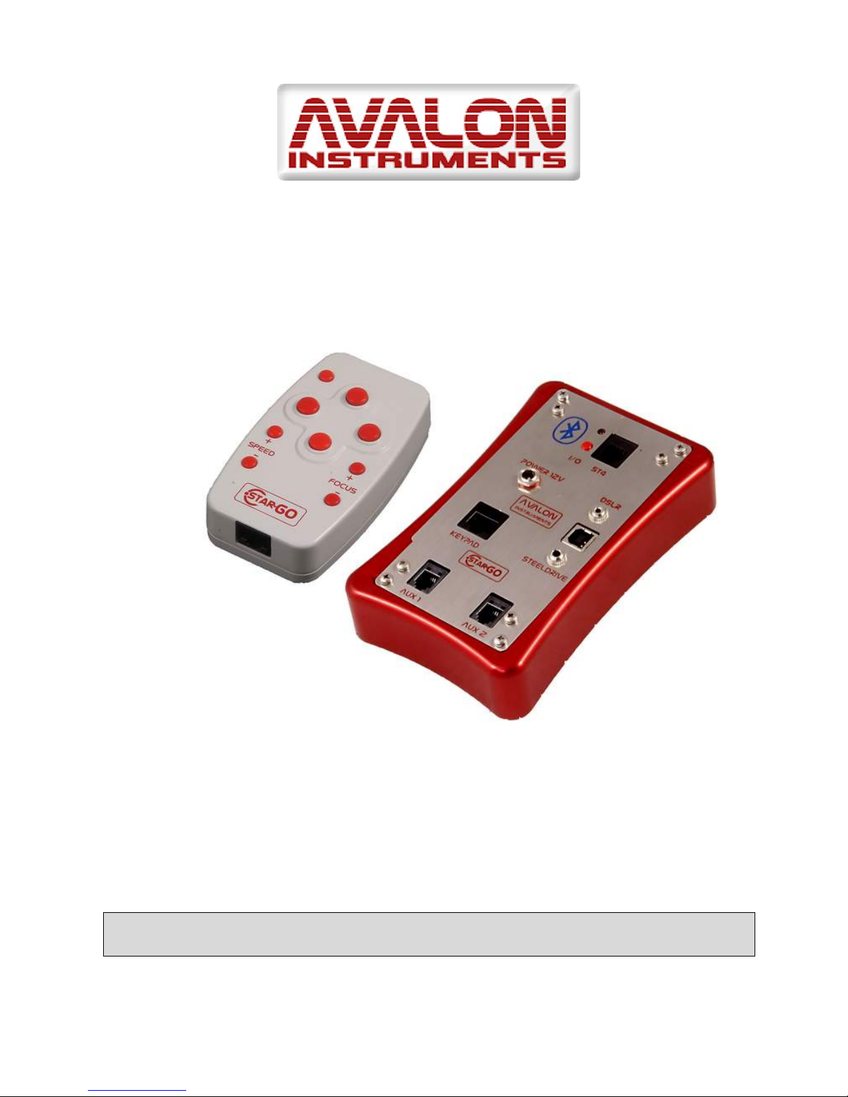
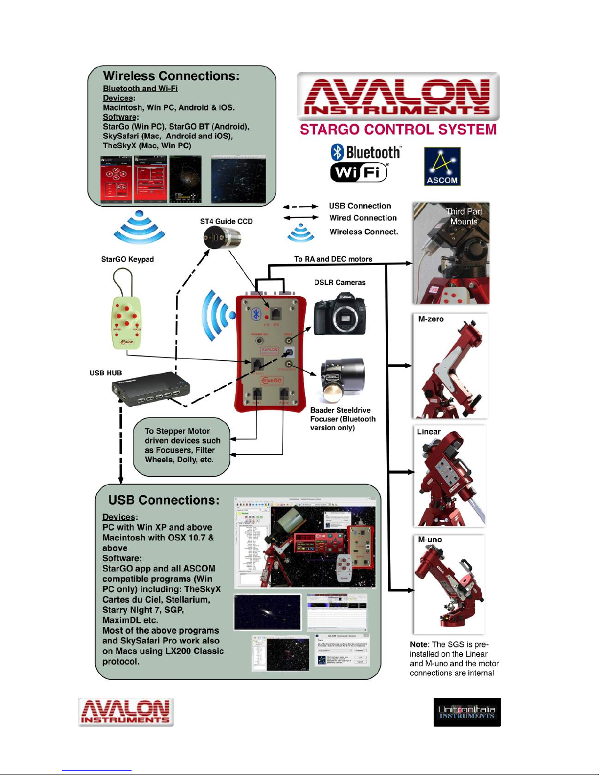
The StarGO Goto Control System is composed of five main components:
1. The StarGO Control Box that can be embedded in the mount as for the Avalon Linear
and M-Uno, or in a separate control box for the M-Zero. Thanks to the programmable
Gear Ratio and the special motor kit, the StarGo
Control Box is also compatible with many mounts
from other manufacturers. It has the ability to
provide a smart interface between the mount’s drive
motors and the external world. Using internal and
user-selected computerized astronomy software
applications, it performs all the necessary
communications with specific components,
including the autoguider, focuser, CCD rotator,
DSRL camera, and other auxiliary devices, using USB connections with
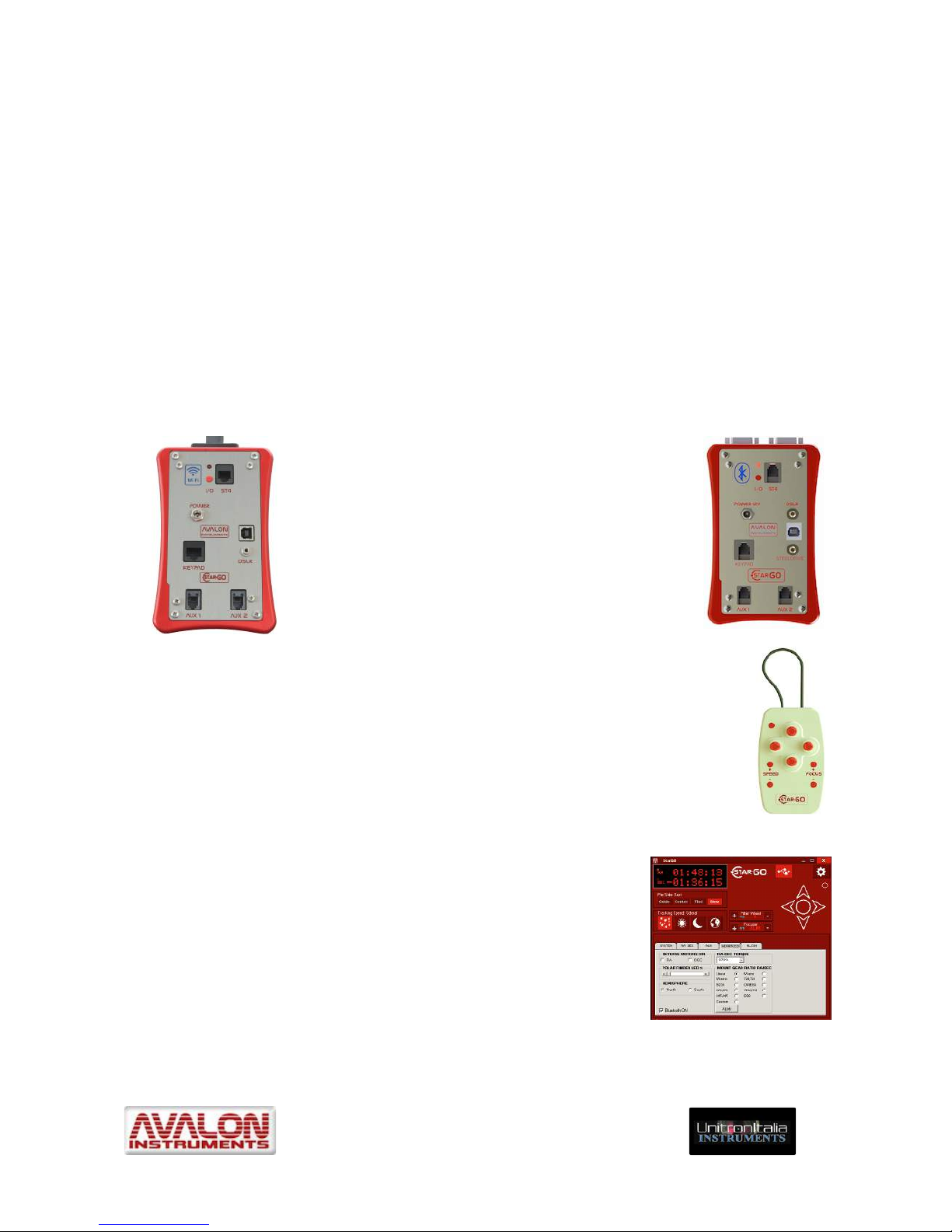
Windows and Macintosh computers. Wireless capability, based on
Bluetooth (right picture) or Wi-Fi (left picture), is also integrated in the
control box unit to interact with intelligent devices such as smartphones,
tablets, Android devices as well as Windows and Mac computers. The
wireless system (BT or Wi-Fi) must be choosen at time of order.
2. The StarGO Keypad is able to physically command the mounts and
perform almost all the most needed operations without the use of a
computer or other control device.
3. The StarGO software, entirely written and compiled by
Avalon Instruments uses a computer to perform all the setup
and management operations, including the control of various
external equipment that can be connected to the control box.
It is also able to perform all the same operations performed by
the StarGO keypad.
Page 8
_____________________________________________________________________
© All Rights reserved! ! !
!
8!
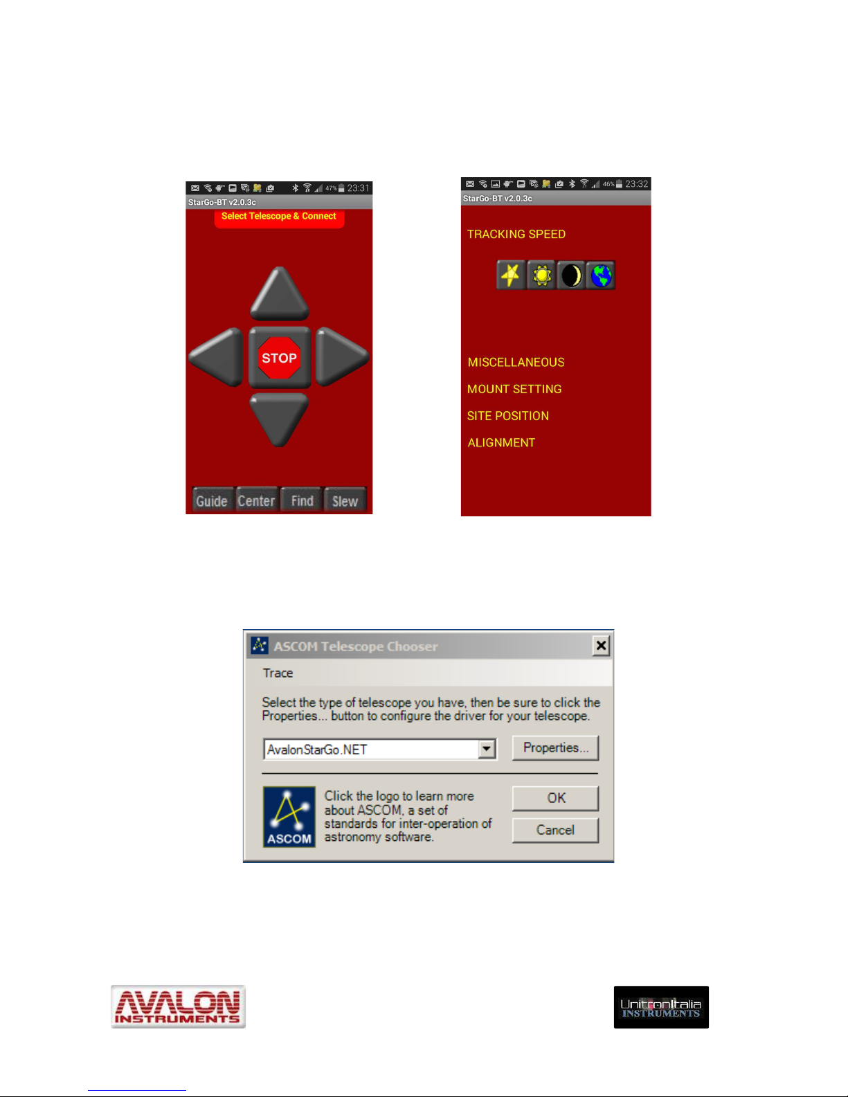
4. The StarGO-BT application for Android devices allows them to interface with the
StarGO control box via Bluetooth connection. With this application the Android devices
become perfect smart-device control pads. This application, as well as StarGO, is under
continuous development to add new functionalities.!
5. The AvalonStargo ASCOM driver makes possible the interaction between the StarGO
Control Box and the vast majority of third party software applications such as Cart du
Ciel, Stellarium, etc. In addition, thanks to the compatibility with the LX200 standard, the
StarGO can work with almost all other software applications.
Page 9

_____________________________________________________________________
© All Rights reserved! ! !
!
9!
2.1 Technical Specifications:
General
Computerized control system based on stepper motor technology
and dual communications (USB and Bluetooth or Wi-Fi).
Operational Mode
Equatorial or Azimuth (for the appropriate mounts)
System Speeds:
• “Guide”: From 0,05 to 0,95X in 0,05X increments .
• “Center”: From 2 to 10X
• “Find”: From 10 to 150X.
• “Slew”: N. 4 speeds ranges (Low, Medium, Fast, Ultra) depending
on the mount “gear ratio” and, for the maximum speed “Ultra”, on
the power supply (at least 15 VDC).
Tracking Speeds
• Sidereal
• Solar
• Lunar
• Terrestrial (No tracking)
RA – DEC Motor
Currents
Typical currents are 0.3 A for tracking and 1.5 A (adjustable) for
slewing.
Data Base
14000 Default objects. The database is easily editable by the user
using a simple text editor. This database is part of the StarGO
software and it may be accessed using a PC.
Input/Output Ports
• USB
• Bluetooth or WiFi
• ST4
Output Ports
• AUX0: (Baader Steeldrive only in Bluetooth version)
• AUX1: Hybrid Step Motor with a max current of 1 A .
• AUX2: Hybrid Step Motor with a max current of 1 A.
Electrical
Characteristics
• Power Supply: 12 – 18 VDC stabilized.
• Current: from 0.3 to 1.5 A (adjustable) in all operating conditions
Page 10
_____________________________________________________________________
© All Rights reserved! ! !
!
10!
Control Operations
• Goto and Sync to celestial objects
• Automatic Meridian Flip
• User definable parking and homing functions
• Programmable Custom Gear Ratio.
User updatable
firmware
USB connection
Operating Temperature
Range
-20 ≈ +40 °C
The StarGo Goto Control System was designed mainly for the Avalon Instruments M-zero,
M-uno and Linear mounts, but thanks to the programmable Gear Ratio and the special
motor kit, it also may be easily used with a variety of mounts from other companies.
StarGo’s design follows the most recent technological developments in this field. It consists
of a very simple hardware interface which facilitates a wide range of applications such as
the management of focusers, filter wheels, autoguiders, DSLR cameras, etc. without the
need of frequent modifications to additional devices. At the same time, it retains the ability
to be controlled by PCs, smartphones and tablets.
To make these characteristics possible, the StarGo Control System intelligence has been
moved to the external software which can be easily updated or modified to work with
different operating systems such as Windows, Mac OSX, Android and others.
The logical interactions of the StarGO Control System with all hardware and software
devices is reported in the following schematic diagram.
Page 11
_____________________________________________________________________
© All Rights reserved! ! !
!
11!
Page 12
_____________________________________________________________________
© All Rights reserved! ! !
!
12!
2.2 The StarGO Goto Control System hardware interface
It is supplied with the following items:
1. Main Board and Aluminium case.
2. StarGO control keypad.
3. Keypad connection cable (RJ45 Standard).
4. USB cable.
5. 12-24 VDC power supply with 110-240 VAC and 12 VDC inputs + cigarette
lighter 12V power cable.
6. A USB flash drive containing the StarGO software and other utilities needed for
its setup and operation, as well as the complete documentation, including this
and other manuals.
7. A foam-lined high-impact carrying case for all of the above
The Main Board for the Avalon Instruments Linear and M-uno mounts comes already
internally installed from the factory. On the M-zero mount it is mounted externally. The
StarGO control box which comes with the Stand Alone Kit is designed to be installed
externally on mounts of other brands.
The StarGO Control Box is an attractive Aluminium case which contains the StarGO
main control board and has external connections to power the motors and other
devices (item 1 above).
This section describes the StarGO control interface and the related keypad.
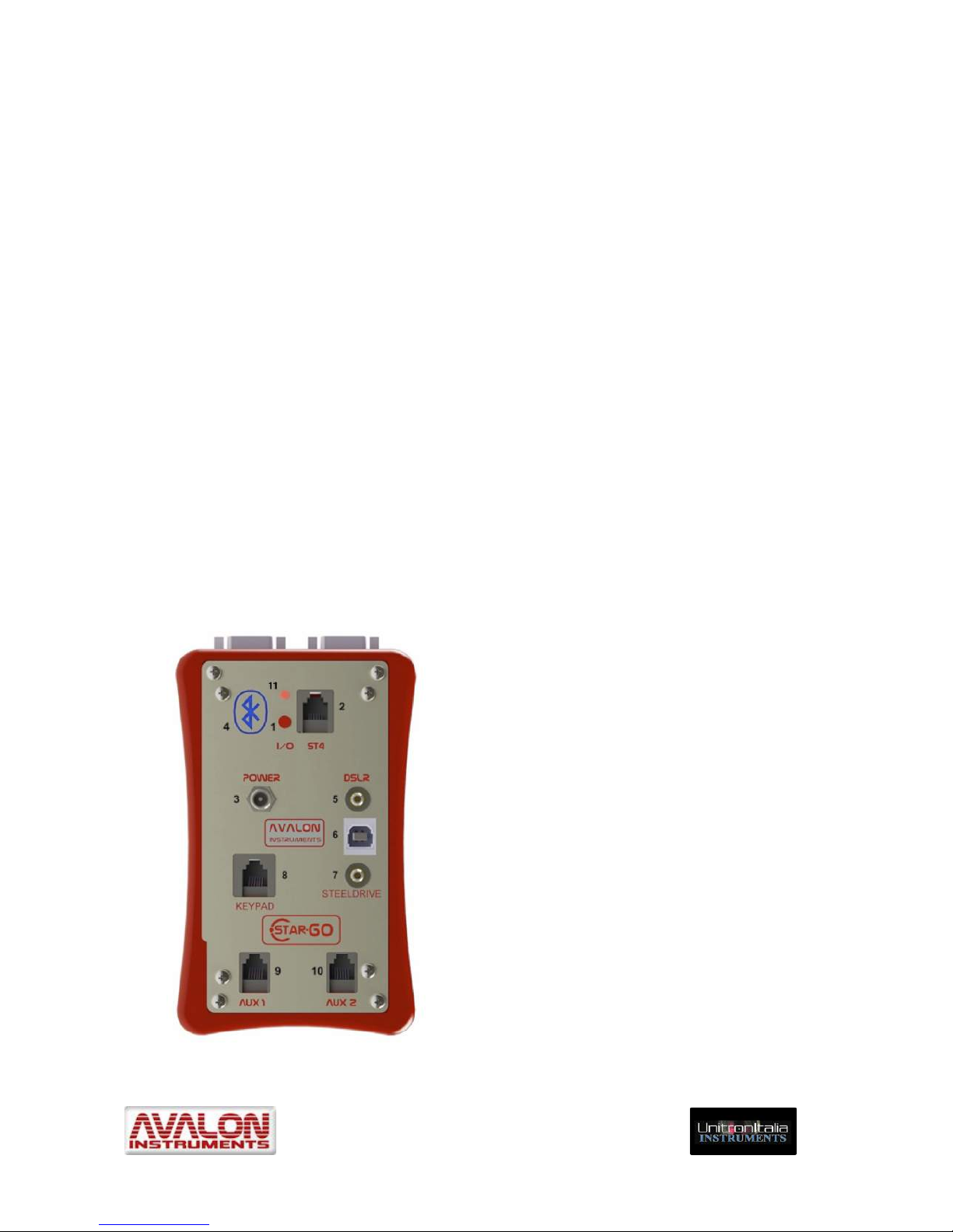
Figure 2.1 illustrates the physical interface of the StarGO control box.
Figure 2.1 StarGO Front Panel
1. On/Off Power button
2. ST4 autoguide port
3. 12-18 VDC power supply plug
4. “Wireless” Bluetooth capability
symbol
5. DSLR Canon exposure
management port
6. USB2 I/O Port
7. Baader SteelDrive focuser control
port (Bluetooth version only)
8. Handheld keypad RJ45 plug
9. Stepper Motor Auxiliary Output
Port (Aux 1)
10. Stepper Motor Auxiliary Output
Port (Aux 2)
11. On/Off LED
Page 13
_____________________________________________________________________
© All Rights reserved! ! !
!
13!
The output port Aux1 and Aux 2 can be used to drive motorised device such as focusers
other than Baader Steeldrive (for example the Avalon Instrument FOCS), Time Lapse Dolly,
etc.
Once the power has been provided to the StarGO, the red LED above the On/Off button will
start to blink, indicating that the StarGO is powered but the RA and DEC motors are
stopped. This means that the mount is not tracking the sidereal movement. To activate
tracking, briefly push either a) the red button (#1) on the StarGO Control Box, or b) one of
the directional buttons (W – E – N – S) of the keypad or c) one of the directional buttons of
the StarGo GUI main panel on the PC. (see figure 4.1).
To interrupt the tracking movement while still leaving the StarGO powered, hold the red
button (#1) down for at least 5 seconds. The red LED will commence blinking once again.
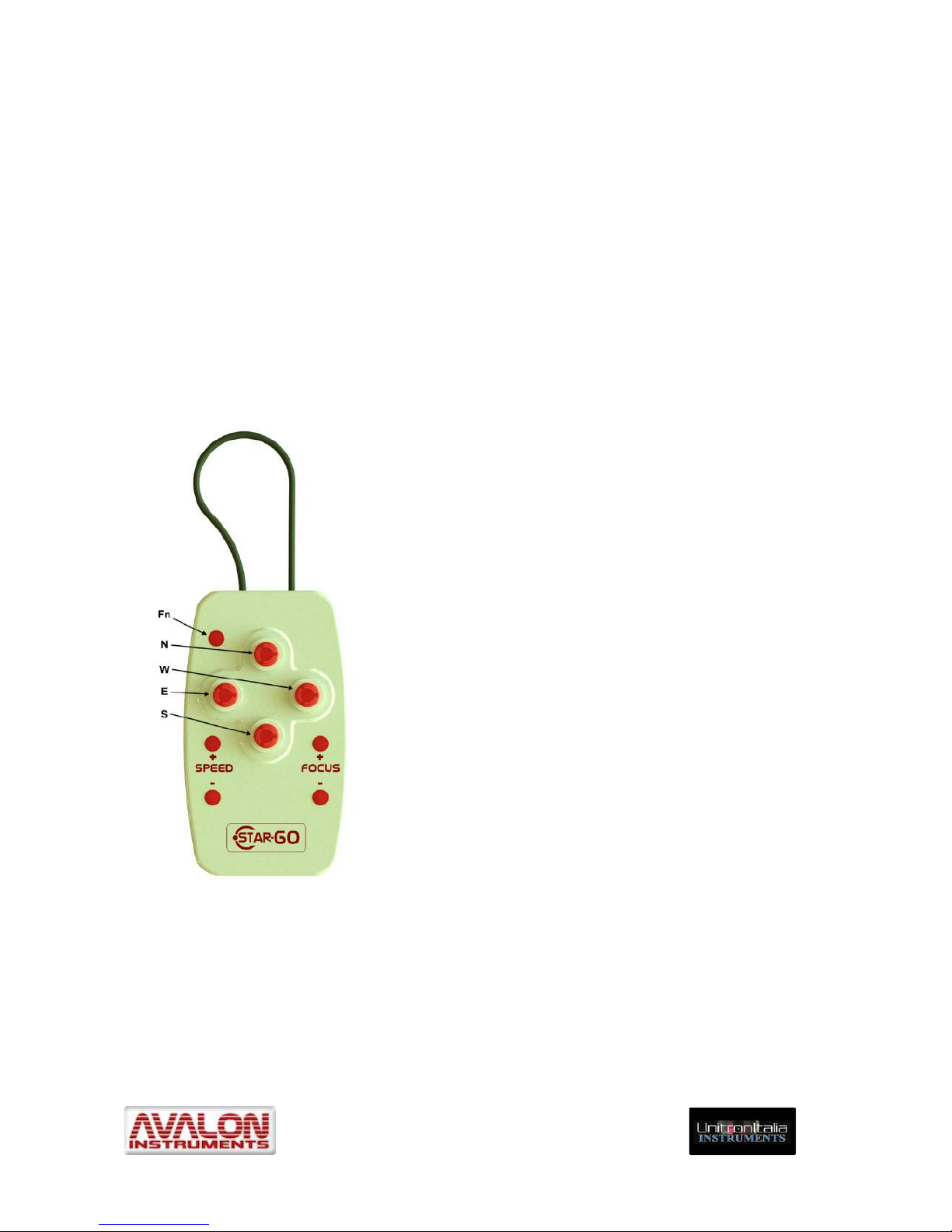
The figure 2.2 illustrates the manual keypad which is connected to the StarGo Control Box
at the plug labelled “Keypad” (#8) with the included RJ45 cable.
Figure 2.2 Keypad
W / E Decreases/Increases the Right
Ascension
N / S Increases/Decreases the Declination
Fn Function Key
SPEED+/- Increases/Decreases the mount’s
movement speed
Fn&SPEED+/- Increases/Decreases the Polarscope
LED light intensity
FOCUS+/ - Controls the in and out movement of
the SteelDrive focuser motor in the
port with the same name. Also
controls the movement of any focuser
connected to either of the two Aux
ports.
Fn&FOCUS+/- Changes the Aux port to which the
changes are sent. (1)
Fn&N / S Select system tracking speed
(Sidereal, Solar, Lunar, Terrestrial)
(2)
Fn&E / W Select telescope max slewing speed
(Low, Medium, Fast, Ultra) (3)
(1) By holding pressure on the Fn key and then pressing the FOCUS+ key, each time the FOCUS key is
pressed, the output port to changes the order: Steeldrive, AUX1 and AUX2. By keeping pressure on
the Fn key then pressing the FOCUS- key the selection order is inverted (AUX2, AUX1, Steeldrive). !
(2) By holding pressure on the Fn key and then pressing the S key, each time the FOCUS key is
pressed, the system speed varies in the order: Sidereal, Solar, Lunar, Terrestrial. By keeping
pressure on the Fn key then pressing N key the selection order is inverted (Terrestrial, Lunar, Solar,
Page 14

_____________________________________________________________________
© All Rights reserved! ! !
!
14!
Sidereal). The system does not memorize the tracking speed as modified and the next time the
system is powered-on, it returns automatically to the default Sidereal speed.
(3) By holding pressure on the Fn key and the pressing the W key, the telescope max slewing speed
varies in the order: Low, Medium, Fast, Ultra. By keeping pressure on the Fn key then pressing E
key the selection order is inverted (Ultra, Fast, Medium, Low). The system does not memorize the
tracking speed as modified and the next time the system is powered-on, it returns automatically to
the default Slew speed.
Page 15
_____________________________________________________________________
© All Rights reserved! ! !
!
15!
3. Software Installation
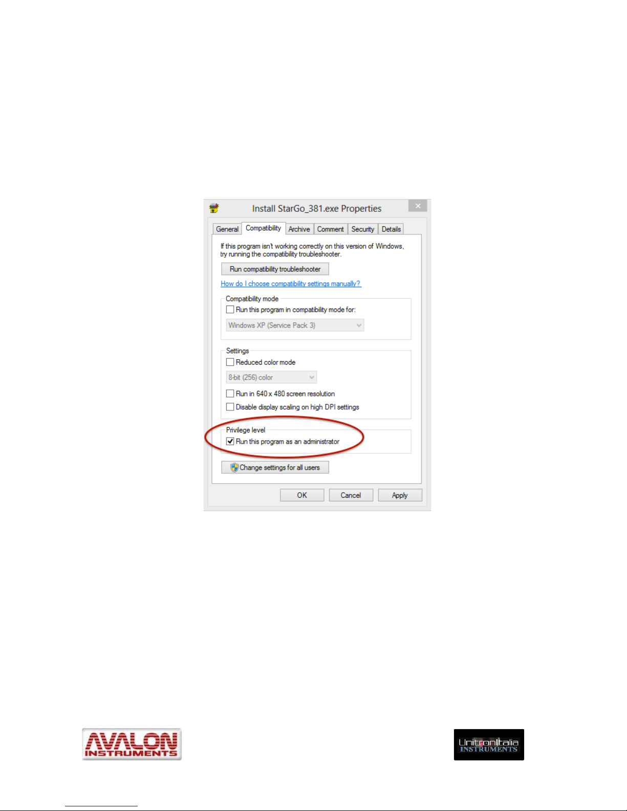
NOTE: In order to avoid software difficulties, especially with more recent operating
systems, it may be necessary to run these applications as Administrator. To enable
this option, select “Execute this program as Administrator” from the Compatibility
window under the Properties tab of the executable files. This can be found within the
Programs\Avalon\StarGo folder. To guarantee perfect compatibility it is necessary
that all other applications (such as planetarium programs, autoguide, CCD and DSLR
management software, plate solving applications, etc.) are also run as administrator.
3.1 StarGo, StarGoLoader application and FTDI driver installation.
To get maximum use of the StarGO system features and to obtain complete mount control,
it is necessary to install the applications supplied on the flash drive.
However the mount is able to track objects, both in equatorial and Alt-azimuth
configurations, even without a connection to a PC or other device.
The StarGO software is provided with an ASCOM driver, making it controllable with most
astronomical applications. During the software installation process, as described below, the
Avalon ASCOM driver, the serial-USB FTDI drivers, the StarGO application and its firmware
and related update utility are installed.
Page 16
_____________________________________________________________________
© All Rights reserved! ! !
!
16!
The use of StarGO in an ASCOM environment with the more popular compatible software
applications is described in detail in a specific document (StarGO – Third Party Software
Use – Instruction Manual).
Note: Before launching StarGO be sure that the ASCOM platform is installed in the
PC (http://download.ascom-standards.org/ASCOMPlatform62.exe). If this is not done, the
program will abort and the Run-Time error message “429” will be generated. Upon
special request Avalon Instrument could supply a version of StarGO not needing the
ASCOM platform.
The StarGO software is provided in a USB flash drive. The software installer file, called
“Install StarGo_xxx.exe”, is located in the folder "Installer-Tutorial-Software".
The step by step software installation procedure, on a Windows 8 computer, is the following:
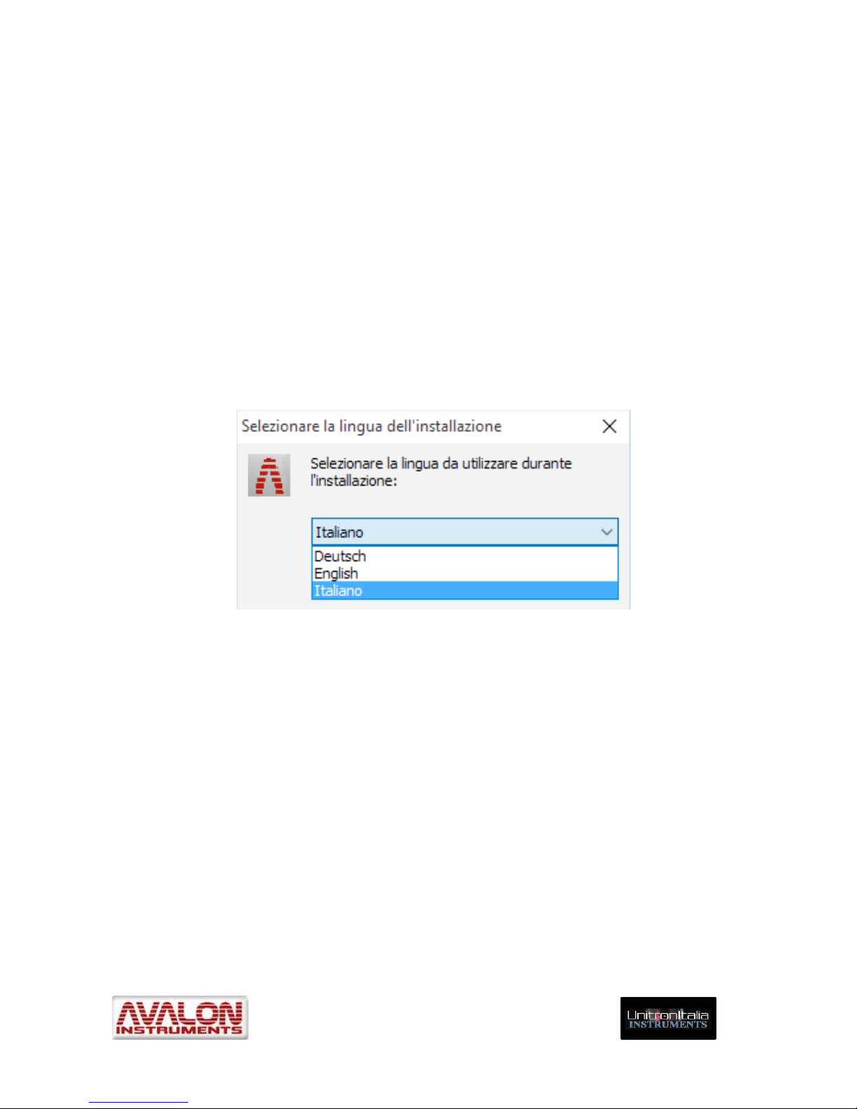
1. Launch the “Install StarGo_xxx.exe” application (xxx is the installer version number).
The installation language chooser will appear. The “InstallWizard StarGo” windows
will appear. Choose the preferred language and than OK:
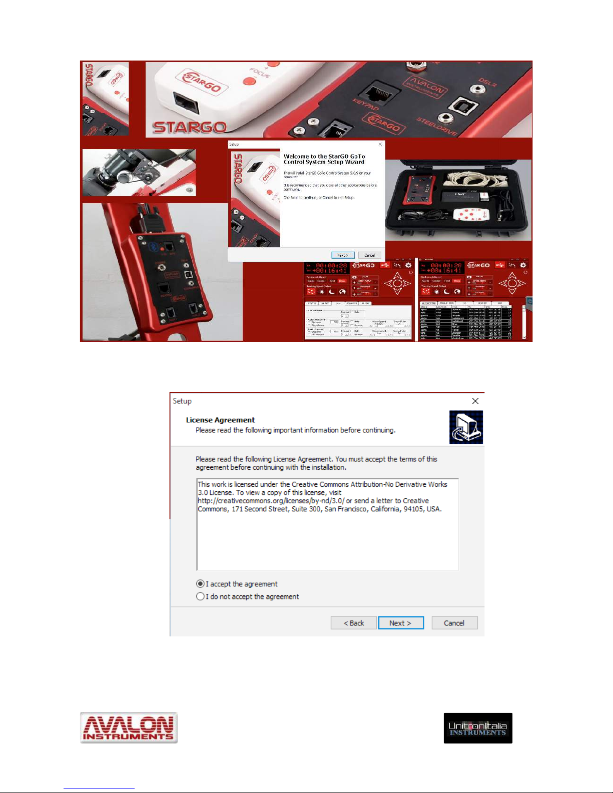
2. The installation splash screen will appear containing the StarGO GoTo Control
System Setup Wizard welcome window. Click Next:
Page 17
_____________________________________________________________________
© All Rights reserved! ! !
!
17!
3. The welcome window inside the splash screen will be replaced by the License
Agreement window. Select “I accept the agreement” and then “Next”.
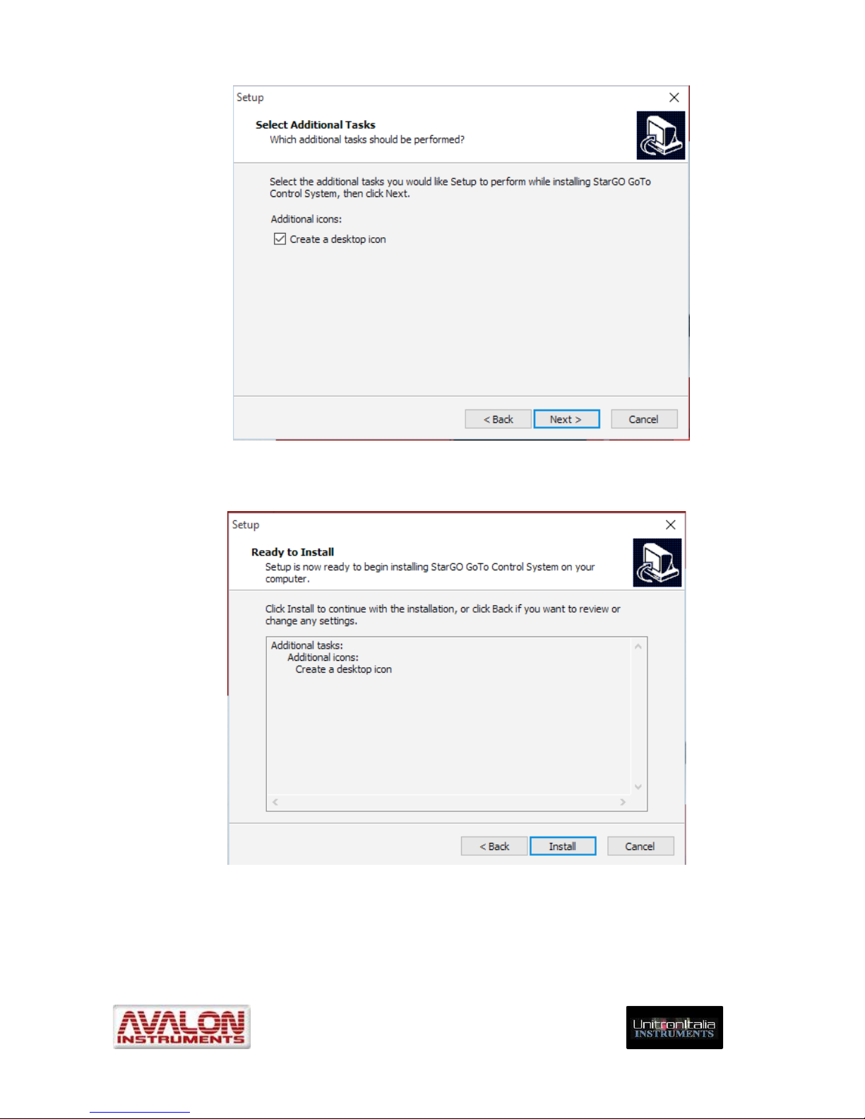
4. The next window will allow the creation of a StarGO desktop icon. It is advised to
accept and then press “Next”.
Page 18
_____________________________________________________________________
© All Rights reserved! ! !
!
18!
5. The next window inside the splash screen will present the summary of the task
selected and proposes to start the installation. Press “Install” button.
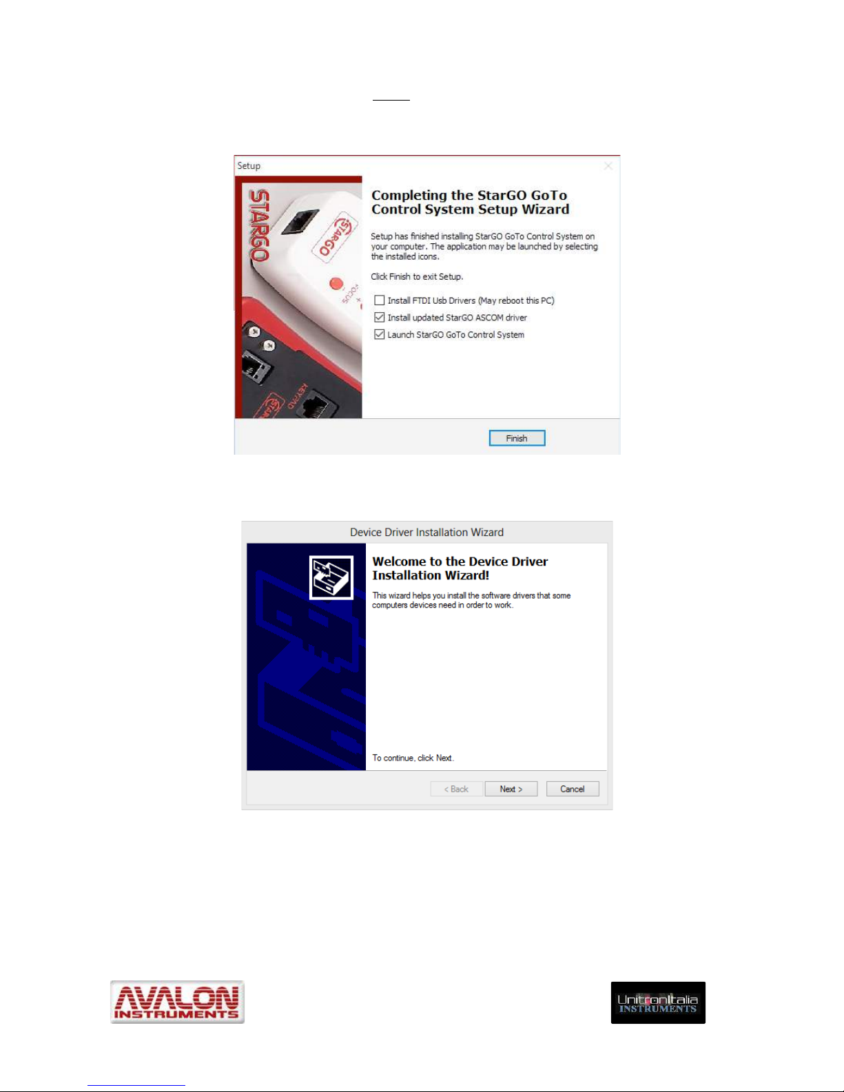
6. At the end of the installation process a window will be presented to finish the
installation process, asking to perform additional operations if needed: install The
FTDI USB drivers, install the most updated StarGO ASCOM driver and launch the
StarGO software at the end of the installation process.
Page 19
_____________________________________________________________________
© All Rights reserved! ! !
!
19!
NOTE: The FTDI serial-USB drivers must be installed during the first installation.
Because they are much more less frequently updated than the StarGO driver, it is not
necessary to install them each time.
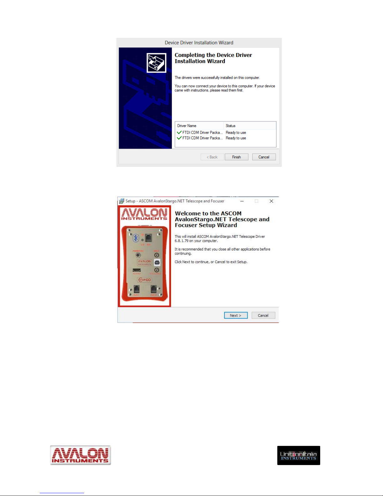
7. Press “Finish”. In case the FTDI driver installation has been selected the “Device
Driver Installation Wizard” will appear.
8. Press “Next”. The windows announcing the correct driver installation will appear.
Press “End” to exit. The new drivers are ready for the USB connection.
Page 20
_____________________________________________________________________
© All Rights reserved! ! !
!
20!
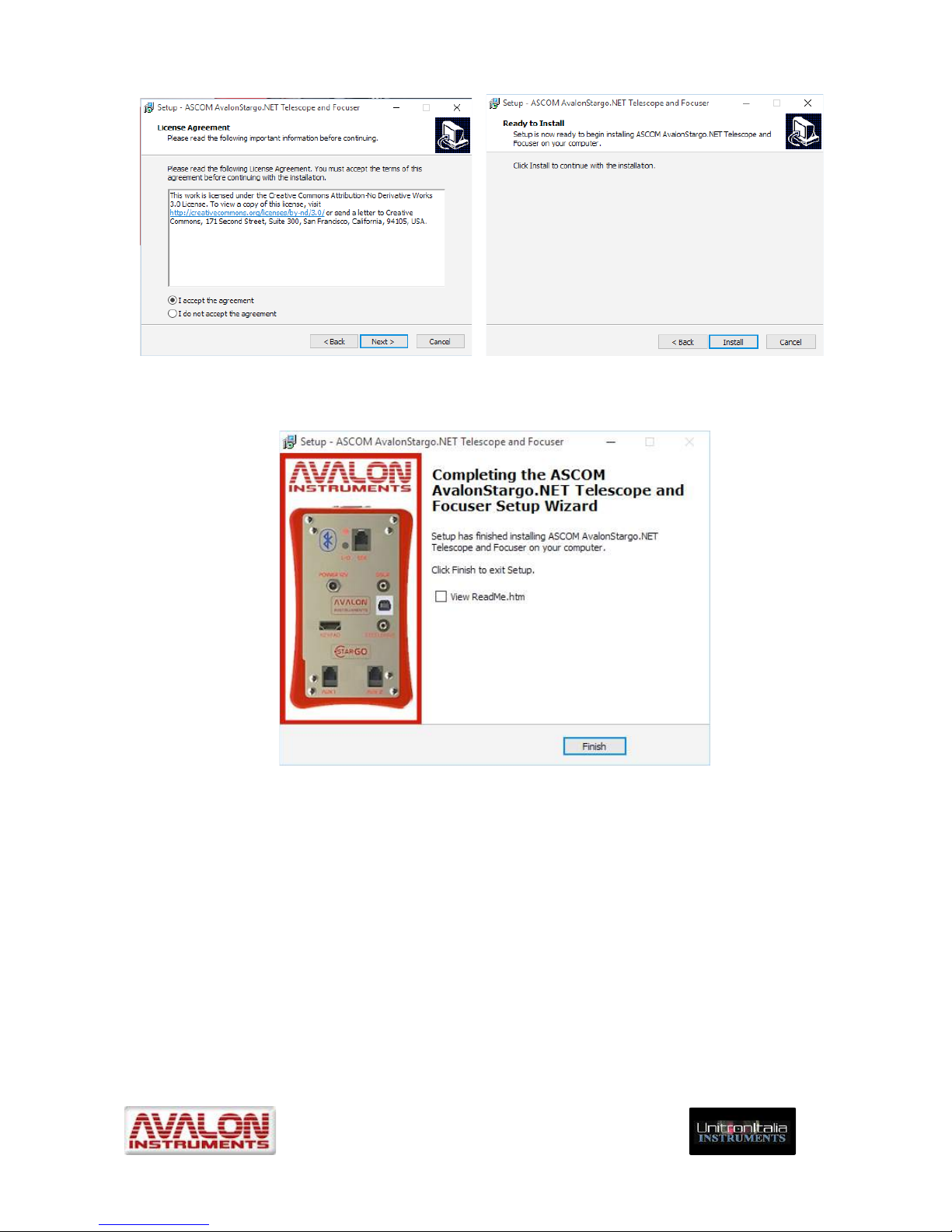
9. After the FTDI driver installation (if selected) the Avalon ASCOM driver installation
wizard will pop up. Press the “Next” button.
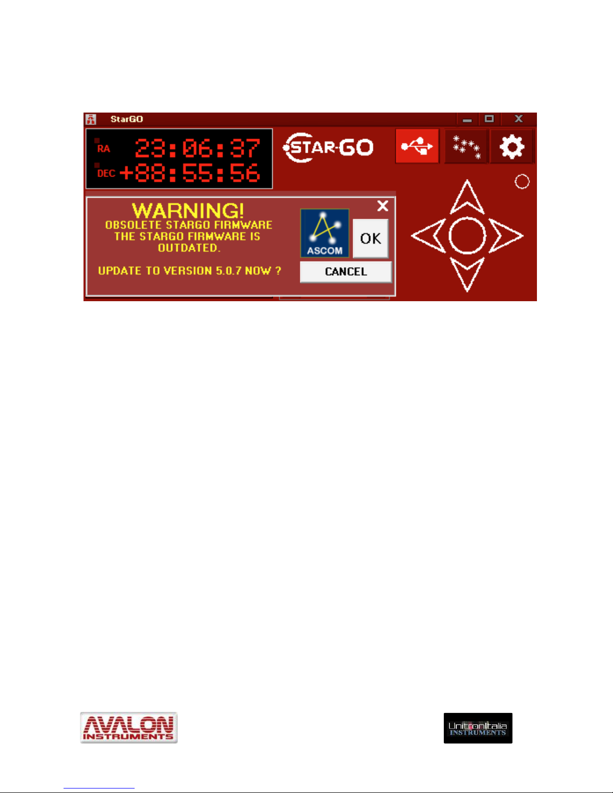
10. Accept the License Agreement in the following window and press “Next”. Press
“Install” on the subsequent window:
Page 21
_____________________________________________________________________
© All Rights reserved! ! !
!
21!
11. A final window will inform that the installation process has been successfully
completed and propose to view the contained Readme file of the installation.
3.2 Software Updating
The StarGO software and firmware are subject to continual improvement and updating, with
additional functions being added all the time. We therefore advise users to frequently
consult the Avalon Instruments website Support page to be assured that their StarGo
software and firmware are the latest updated versions.
The updating process consists of repeating the installation operations previously described
in Software Installation, Section 3.1. Items 4 and 5 related to the serial/USB driver
installation need not be performed at this time.
Firmware Warning
Page 22
_____________________________________________________________________
© All Rights reserved! ! !
!
22!
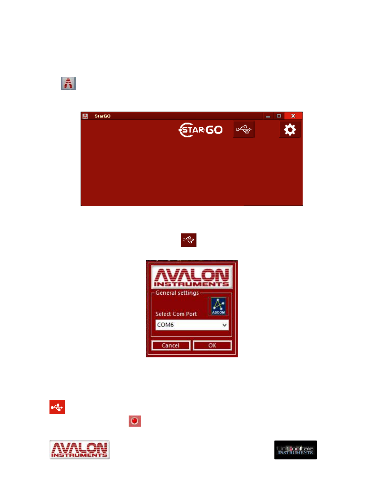
When a new StarGO software application is first launched and connected, it is possible that
a warning message will appear indicating that the existing StarGO firmware within the
hardware is obsolete and incompatible with the newly installed software.
Figure 3.1
If this message appears, it will be necessary to update the firmware following the
instructions given in Section 7. The file containing the newest firmware to be chosen will be
the most recent one among those available in the StarGO folder. When the firmware
updating has been completed it is necessary to restart the StarGO application and verify
that the “Obsolete StarGO Firmware” warning does not re-appear.
Page 23
_____________________________________________________________________
© All Rights reserved! ! !
!
23!
4. StarGO program description
4.1 Graphical User Interface (GUI)
When using StarGo with a computer or other device, activate the StarGO GUI by clicking
the icon created on the desktop during the program installation. The user interface
appearance is shown in Figure 4.1a.
Figure 4.1a – StarGO Main Panel before connection
To animate the GUI it is necessary to perform the StarGO connection with the hardware. To
do this press the button with the USB icon and the COM port selection window will
appear.
Figure 4.1b – COM Port setting
The connection will be established by selecting the correct COM port (normally the port
suggested in the Select Com Port menu) and pressing OK. The USB icon will be highlighted
and with the sudden appearance of a blinking red LED, it will signal the correct
connection. The red LED on the GUI has the same functions as the button installed on
Page 24
_____________________________________________________________________
© All Rights reserved! ! !
!
24!
the StarGO hardware (item #1 of Fig. 2.1). If at the end of the previous session the mount
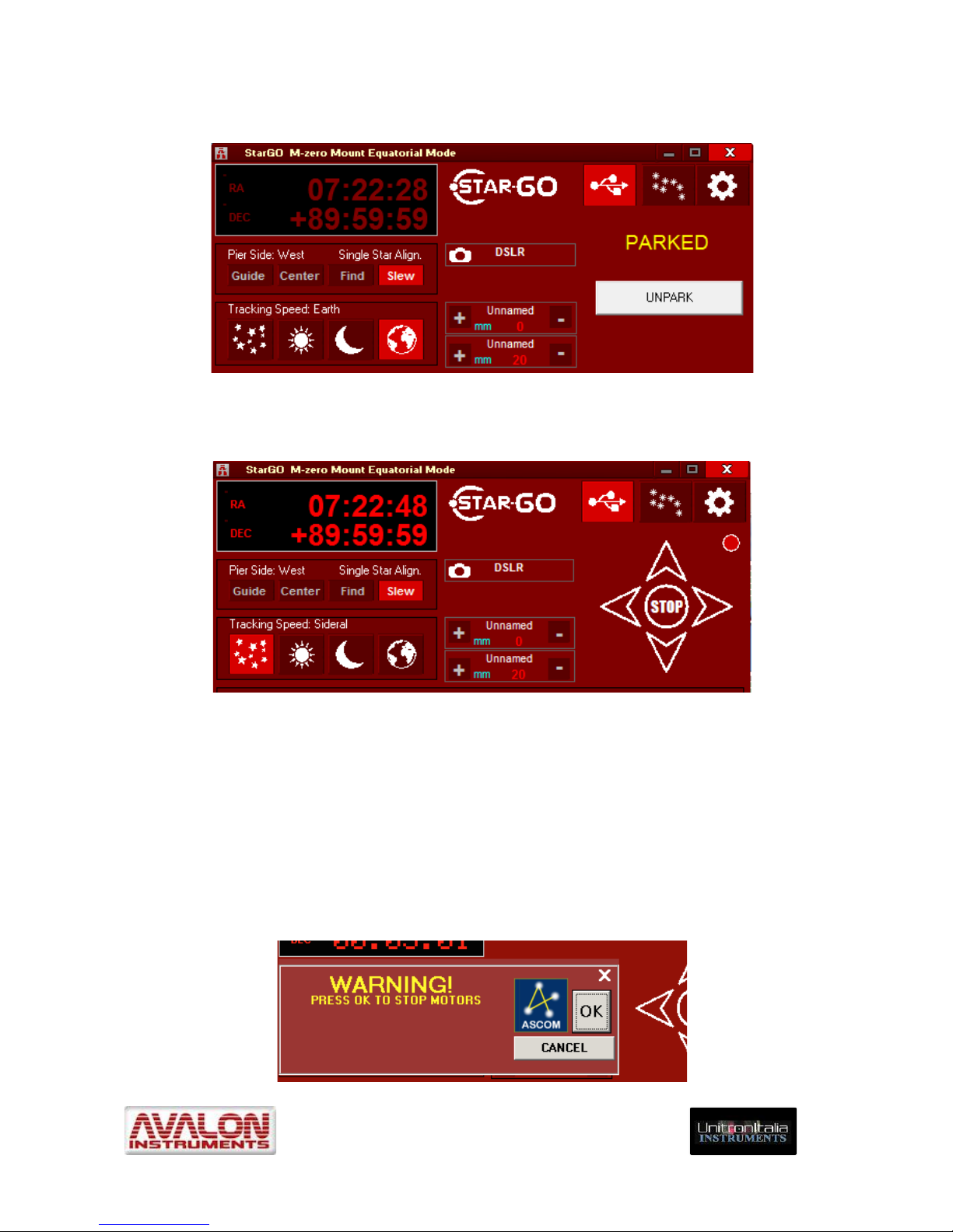
has been correctly parked, the main GUI panel will appear as follows:
Figure 4.1c – Main Panel with the mount parked
If the mount has not been not parked or after the UNPARK button is pressed, the GUI will
look like this:
Figure 4.1d - Main Panel with the mount unparked
A quick click on the LED or on one of the directional arrow buttons will activate the sidereal
tracking and the LED will remain on (same as the physical LED on the StarGO) obtaining
the same result of a brief pressure of the mentioned physical button #11 in the StarGO
hardware.
Just as holding the red power button on the StarGo Control Box for longer than 5 seconds
will cause tracking to stop, a double click on the LED symbol will have the same effect. The
red LED on both StarGO Control Box and the LED software symbol will flash as tracking
stops. This action will initiate a warning message and a confirmation to stop the tracking
motors.
Page 25
_____________________________________________________________________
© All Rights reserved! ! !
!
25!
4.2 Parameter setting
Pressing the setup button on the upper right, the GUI extends to show the mount
parameter setting panel. As seen in Figure 4.2, this panel contains five tabs for setting
different parameter types.
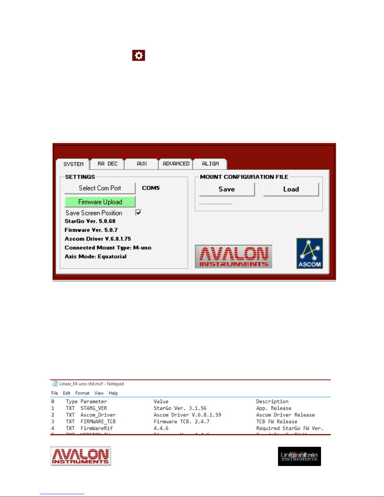
4.2.1 System Panel
The SYSTEM tab allows the selection of the StarGO connection COM port number, as
seen in Figure 4.1b and the upload of a newer firmware version. The “Save Screen
Position”checkbox selects if the StarGO GUI position on the screen should be saved.
Figure 4.2 – “SYSTEM” Panel
This panel reports also the StarGO software, firmware and ASCOM driver versions as well
as the type of mount and the axis mode (equatorial or alt-azimuth).
The timeliness of the given versions of firmware and software is evaluated by the software
itself and, in case they are not current, the user is warned and advised to update.
Saving the “Mount Configuration File” containing the mount configuration parameters (this
file has the .mcf extension) is done by pressing the Save and Load buttons. The names of
the parameter files to be loaded are shown below these buttons.
The Configuration Files have the following format:
Page 26
_____________________________________________________________________
© All Rights reserved! ! !
!
26!
The above figure shows only a few of the mount parameters. The total number of the
parameters is normally of several tens. Their values depend on the software version, the
mount type and the custom settings. With the StarGO installation several default .mcf files
are copied in the StarGO folder, related to the Avalon Instrument mounts and to the
StarGO standalone kits available for supported mounts of other brands. Other configuration
files may be added by the user, containing different customized setups for the owner’s
mount(s), using the described Save button. The most suitable configuration file is uploaded
to the StarGO using the Load button.
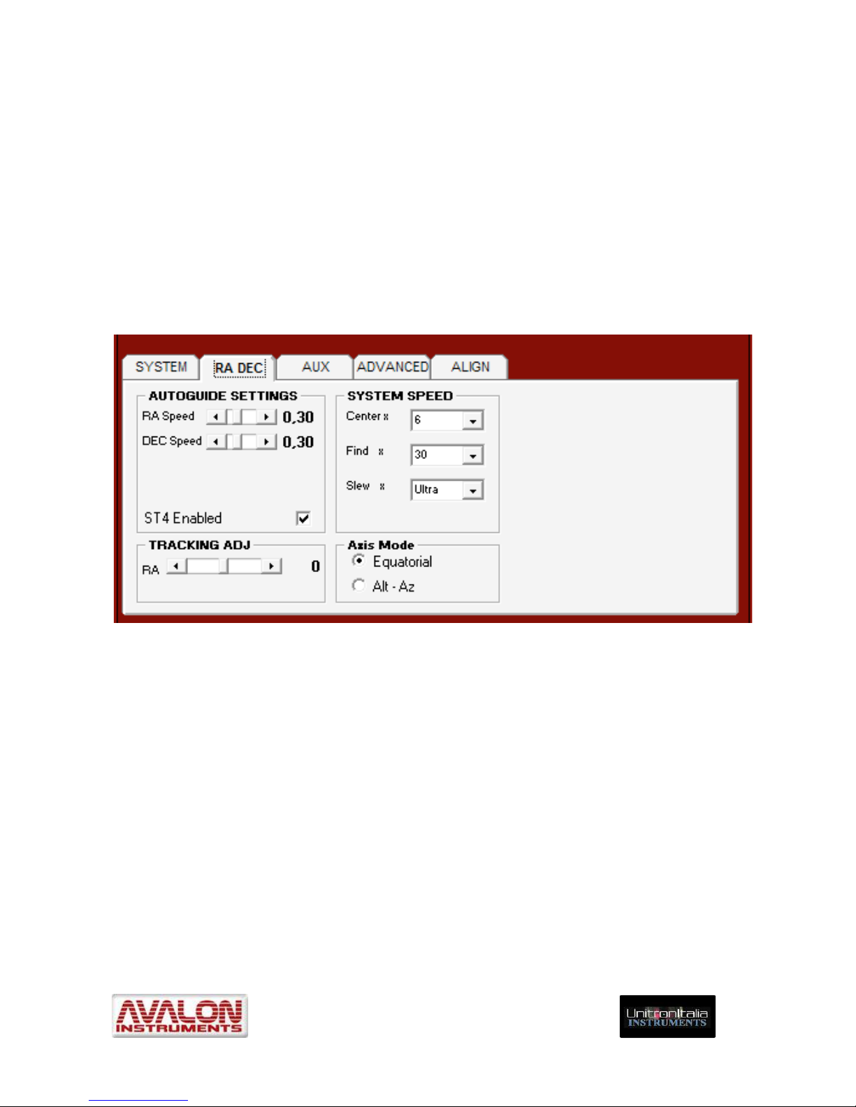
4.2.2 RA DEC Panel
Pressing the RA-DEC tab opens the panel shown in Figure 4.3 which enables access to the
guide settings of the mount.
Figure 4.3 –“RA-DEC” Panel
The “AUTOGUIDE SETTING” frame allows the regulation of the auto-guiding speed, with
increments of 0.05x times the sidereal speed. This regulation can be performed
independently for the two axes. It has effect for the signal coming from the ST4 port and
forthe pulse guiding signals coming from the USB ports. The check box “ST4 Enable” allows
to enable/disable the ST4 port.
NOTE: If a ST4 cable is still connected and it is impossible to move the mount, it is
strictly necessary to unplug the cable or disable the ST4 using this check box. This
malfunction event happens because some CCDs leave the port locked after use,
preventing to use other moving speeds then guide.
The “SYSTEM SPEED” frame enables changing the values of moving speed when using
the directional buttons of the main panel of the StarGO GUI or the Fn&E / W keys in the
keypad.
The available slew speeds are: “Low”, “Medium”, ”Fast” and “Ultra”. The latter requires at
least 15 VDC to be supplied to the system.
Page 27

_____________________________________________________________________
© All Rights reserved! ! !
!
27!
The AXIS MODE frame allows the selection of Equatorial or Alt-Azimuth mount working
mode. The M-zero mount is capable of operating in either mode. The selection of the
“Show” check-box on the right of the “Alt-Az” mode selector will force the main display to
show the Alt-Az coordinates in place of the Equatorial ones.
4.2.3 AUX Panel
Figure 4.4 – “AUX” Panel
Clicking on the “AUX” tab brings up a panel (Figure 4.4) that controls the setting of one
auxiliary port dedicated to a Baader Steeldrive focuser and the two AUX 1 and 2 ports
controllable by the StarGO. The latter ports can drive stepper motors for specialized
functions such as motor driven focusers of other brands, filter wheels, CCD rotators, etc.
The “STEELDRIVE” frame only allows the setting of a decimal number (see note below)
because all other parameters are fixed and internally set by the focuser’s manufacturer.
The two frames below, AUX1 and AUX2, contain the parameters pertaining to the auxiliary
devices as follows
• Step/mm – Step/degree: Device speed measurement type (linear/angular) and
related values.
• Decimal: Number of decimal to be shown in the main panel (see figures 4.4a and
4.4b) and in the separate windows (see section 4.4).
• Show checkbox: Show or Hide the controls in the main panel (see figures 4.4a and
4.4b).
• Reverse checkbox: Reverse the motor movement direction.
• Motor Speed cursor: Low, Medium, Fast, Ultra.
• Step/Pulse cursor: Step/Pulse ratio from 0 (none) to 24.
Page 28

_____________________________________________________________________
© All Rights reserved! ! !
!
28!
NOTE: The motors driven by the AUX 1 and AUX 2 ports are disconnected from the
power once they reach the due position. It means that in this state they do not absorb
any current but are not able to keep mechanical loads requiring an active effort.
NOTE: In all three frames of this panel it is possible to define the number of decimal
digits that will be shown in the main panel or in the separate windows (see section
4.4). Furthermore, it is possible to change the Aux port denomination by double
clicking over the frame tab.
Fig- 4.4a – SHOW BUTTONS checked… Fig. 4.4b - …and unchecked
4.2.4 ADVANCED Panel
Clicking on the “ADVANCED” tab brings up a panel in which base parameters are selected
during the installation phase and rarely used thereafter. (Figure 4.5).
Figure 4.5 – “ADVANCED” Panel
The “REVERSE MOTOR DIRECTION” frame allows the inversion of the motor rotation
direction if one or both the mount axes are moving in the wrong direction.
The “POLAR FINDER LED” frame sets the intensity of the polar scope LED during the polar
alignment operations (for both types of polar scope available).
Page 29

_____________________________________________________________________
© All Rights reserved! ! !
!
29!
NOTE: The LED is set to 0 (off) when the system is powered on. It is possible to vary
the LED intensity also by simultaneously pressing the Fn and SPEED+ or SPEEDkeys on the keypad.
The hemisphere in which the telescope is located is set through the “HEMISPHERE” frame.
The Bluetooth capability can be switched ON by selecting the checkbox in the bottom-left
corner.
The last two frames of the ADVANCED tab are related to the choice of the mount on which
the StarGo system will be used and to the setting of both the RA and DEC motor torque (in
percentage of the maximum value). In the “MOUNT GEAR RATIO RA/DEC” frame the type
of mount is selected, on the base of its Gear Ratio, In particular the Avalon mounts Linear,
M-uno and M-zero are nominally indicated.
Starting from firmware version 4.0.0, the motor torque management system has become
dynamic. For the regulation of the RA-DEC Torque value, please refer to the following table:
Mount
(Voltage)
Linear / M-uno
(12 V)
Linear / M-uno
(15 V)
M-zero
(12 V)
M-zero
(15 V)
Max Slew Speed
Fast
Ultra
Fast
Ultra
Torque
70%
70%
50%
50%
NOTE: As regards the Stand Alone kit to be used on third party mounts please use
the specific mount configuration file that comes with the installer.
4.2.5 ALIGN Panel
The last panel is related to the setting of the observation site geographical parameters and
to the mount parking operations in specific positions such as Park, Home, etc.
Figure 4.6 – “ALIGN” Panel
The left frame of the ALIGN panel (“OBSERVATORY LOCATION”) allows up to six
observation sites to be set and saved by inserting their geographical coordinates (Latitude
and Longitude).
Page 30

_____________________________________________________________________
© All Rights reserved! ! !
!
30!
NOTE: To operate the mount in Alt-Azimuth mode (for the mounts that allow this
operating mode) it is normally sufficient to use a smartphone or tablet equipped with
suitable software such as SkySafari (see the following sections 4 and 5), along with
to the control keypad. The StarGo retains the chosen operational mode in its
memory.
The “PARKING” frame allows management of the key positions that the mount will use at
the end of the operating session or resetting of the starting point if needed during the
session. The meaning of the four buttons is the following:
• Set Park button places in the StarGO memory the position in which the telescope
shall be parked.
• Park button moves the mount parking in the positions previously selected. Using the
Park function enables the mount to be switched off and restarted, even after many
days, without losing the sky alignment.
• Slew to Home Position buttons brings the mount to the Home position previously
defined with the Sync Home Position function corresponding to the starting position
to which the Sync Home Position has been previously set.
Two check boxes are on the bottom of the frame. The first “Use Multi-Star Model” enables
the StarGO to accept the sky model built using the X-Solver tool (see the Appendix). The
second check box tells the mount to move up a Meridian Flip before the Meridian is
reached.
The “Sync Home Position” button, below the PARKING frame, allows synchronization
of the telescope Home Position with the established mount home position (CWD position
with the counterweight bar down and the telescope pointing North).
Figure 4.7 – Main Panel with a parked mount
Whenever the mount stops at the PARK position, the StarGO GUI will suddenly change.
The directional buttons will be replaced by the information indicating that the mount is now
in “PARKED” status (see figure 4.7). A new push button will become available to perform
mount “UNPARK” operation.
Page 31

_____________________________________________________________________
© All Rights reserved! ! !
!
31!
4.3 Warning Description
The StarGO is provided with a warning system to alert the user when setting functions that
require more attention or that can jeopardize the correct mount operation.
The first of such alarms is presented when there is a significant disagreement between the
version of the firmware installed in the StarGO Control Box and the software being used.
This can occur quite frequently because both these elements are continuously improved by
Avalon Instruments. That is why we repeatedly suggest checking to see if new firmware and
software updates are available. New versions are regularly distributed through Support!
page of the Avalon web site.
When StarGO, during connection, determines that firmware and software versions are
incompatible because they are at different stages of updating, the following warning will
appear over the main GUI panel:
Clicking on the OK button will allow operation to continue normally. However, possible
malfunctions could occur if any important software changes or updates have taken place
since the previous version of the software was used. It is therefore important to follow the
warning suggestion to update to the latest firmware version.
A similar warning is generated if the software version is found to be obsolete, compared to
the StarGO firmware version. Similarly, if this is the case, the suggestions given above shall
be followed.
Another warning, important for safe mount operation, appears when the user attempts to
increase the motor RA.DEC Torque over the 100% threshold in the ADVANCED panel:
Page 32

_____________________________________________________________________
© All Rights reserved! ! !
!
32!
Increasing the motor torque could potentially cause a damaging and dangerous overheating of the motors and associated hardware. For that reason it is advisable to remain
below the specified threshold. Pressing the “Yes” button will cause the StarGO to be
restarted, with the loss of all operations in progress.
The last alarm is generated in the SYSTEM panel. A setup file is open, indicating there is a
change in the mount type, gear ratio or other main parameters. This alarm warns the
operator that restarting the StarGO is required to complete the action.
4.4 Using the special features of the Main Graphical Area
Main GUI
This section describes in greater detail all items and features in the Main Control Panel of
the GUI, which are not described or are only briefly mentioned in the previous sections.
The instructions of this section are applicable in both
equatorial and alt-azimuth modes.
The large window on the upper left angle shows the
current values of Right Ascension RA and Declination
DEC coordinates of the telescope.
The directional buttons on the middle
right control the movements of the telescope in RA and DEC. The central
circular button immediately stops all movements in progress whether the
telescope is in operation.
The speeds at which the directional buttons operates the mount (System
Speed) are chosen using the buttons in the frame below the RA-DEC display.
The values of the system speeds are set in the RA DEC panel (see section 4.2.2).The label
above the buttons indicates that the mount is not yet aligned to the sky (“System not
Aligned”) or the telescope pointing side (“Pier Side: East” (or West”))
Page 33

_____________________________________________________________________
© All Rights reserved! ! !
!
33!
The bottom left window contains the buttons to choose the telescope “Tracking” speeds.
“Tracking Speed” is the speed (Sidereal, Solar, Lunar and Terrestrial) used by the
telescope to follow the several types of celestial objects as they appear to move across
the sky.
Clicking on the first button in the “Tracking” row selects sidereal speed. This speed remains
obviously fixed because most celestial objects move at a constant speed due to the
constant speed of the earth’s rotation. The Sun and Moon move at faster speeds across the
sky and therefore require faster tracking speeds.
These speeds are selected by use of the Solar and Lunar buttons in the “Tracking” row). If
the terrestrial speed is selected, the mount stops and remains motionless relative to the sky,
but the display shows the RA changes due to the sidereal motion of the sky.!!
!
DSRL management
NOTE: To enable this button in the Main GUI it is necessary to select the DSRL
SHOW check boxes inside the SHOW BUTTON sub frame in the Aux Panel (see
section 4.2.3, figure 4.4).
The StarGo application is able to efficiently manage photographic imaging with a DSLR
camera, using suitable cable. To use this feature it will be necessary to connect the camera
to the port (#5 in Figure 1.1) on the StarGO Control Box using the suitable cable.Activate
the DSRL function by pressing the button with the same name in the Main GUI.
Clicking on the DSLR button causes a new window to appear (Figure 4.8), allowing
StarGO to set up all photographic parameters for astrophotography and time-lapse.!!
Page 34

_____________________________________________________________________
© All Rights reserved! ! !
!
34!
Fig. 4.8 – DSLR Control
The following parameters are set in the three drop-down menus:
• Pre Shot for Sony Camera: As the name implies, this parameter is applicable
only with Sony DSLR cameras. These need a pre-shot command to raise the
internal reflex mirror before the actual shot.
• Exposure (sec): The length in seconds of each single exposure.
• Delay (sec): The length in seconds of the time gap between successive
exposures.
• Total N. Shot: The total number of exposures to perform.
The controls have been designed with the ability to use “Time Lapse” imaging.
The total time in seconds is reported in the window in the upper left corner.
The “Start” button initiates the sequence of the exposures. The “Stop” button interrupts
the sequence before the total number of shots is carried out.
The “Resume” button re-starts a sequence that has been previously interrupted.
The “Shot” button allows the execution of single shots of variable exposure time. Upon
first clicking on the “Test” button, the exposures start. The second time the “Shot” button
is clicked the process is interrupted..
Below the camera parameters are the commands to operate the auxiliary motors
connected to the Aux1 and Aux2 ports and to operate the RA and DEC motors to move
the mount axes.
Page 35

_____________________________________________________________________
© All Rights reserved! ! !
!
35!
Using these functions with the mount in Alt-Azimuth mode, it will be possible to easily
perform photographic panoramas or dynamic time lapse images.
Finally, at the bottom of the DSLR control windows is a box for choosing the action to be
performed at the end of the photographic sequence.
Steeldrive and Aux ports
The matrix of buttons under the DSLR buttons allows controlling the devices connected
to the three AUX ports of the StarGO (ports N. 7, 9, 10 of Figure 2.1).
NOTE: To enable this buttons in the Main GUI it is necessary to select the
STEELDRIVE, Aux2 and Aux1 check boxes inside the related sub frames in the Aux
Panel (see section 4.2.3, figure 4.4).
The user shall perform the setup of the AUX ports parameters as described in Section
4.2.3 “AUX Tab”. Clicking over the name of the device in the related sub frames, a new
input window will appear as follows.
In this window it is possible to insert new names for the device connected to each of the
Aux ports. This name will appear in the above matrix. Also the gauge units defined in the
AUX Tab will be reported in the matrix for each device. In the following example the
“Steeldrive” port controls a Steeldrive focuser mounted in a C11 telescope, guide scope
focuser is connected to the Aux1 port and the Aux2 port controls a filter wheel.
Double clicking on the name of the devices in the matrix above will bring up one of three
new auxiliary windows to allow the insertion of the required parameters for motor control
of the selected device. The three windows, seen below, are very similar in appearance.
Page 36

_____________________________________________________________________
© All Rights reserved! ! !
!
36!
The positional values may be linear as, for example, focuser extraction or angular rotation in
degrees of a filter wheel.
The five buttons in each window allow easy management of these parameters:
• The GOTO button perform the repositioning of a device to the value introduced in the
display;
• The Zero button is for zeroing out the display value;
• Save will allow the saving of the introduced parameters, otherwise these will be lost
at the StarGO system is exited;
• Sync will enable the synchronization of the device position with the value reported in
the selected row of the table;
• STOP will halt all the device motor movements in case of need.
The display will show the current values of the parameters, including the measurement
units.
The two +/- buttons enable the manual movement of the related device in either of the two
directions in a continuous manner.
The six small buttons with the numbers -1, -0.1, -0.01, +0.01, +0.1, +1 will move the
associated device in a fixed value defined by the number on the used button.
Double clicking on the small GoTo buttons in the table will move the device to the chosen
position. The values of the Posiz. column are manually introduced, corresponding to a
well defined position.
Celestial Database
The StarGO system is provided with a Data Base of about 14,000 objects, including
practically all the astronomical objects which are interesting for astrophotography or for
telescope management, such as the reference stars. See Figure 4.9.
The button with the Big Dipper icon allows access to the StarGO celestial object
database.
Page 37

_____________________________________________________________________
© All Rights reserved! ! !
!
37!
NOTE: To enable this button it is necessary to select the Catalogue checkbox in the
SHOW BUTTONS frame of the Aux Panel (see section 4.2.3, figure 4.4).
Figure 4.9 – Celestial Object Database
The Database window is subdivided into several sections that may be accessed through
related tabs, as illustrated in the figure 4.8 above.
The DB organization is very simple. Each tab corresponds to a specific astronomical
catalogue as follows:
ALIGN_STAR 72 objects
DOUBLE_STAR 39 objects
Herschel 400 400 objects
IC Catalogue 5383 objects
MESSIER Catalogue 110 objects
NGC Catalogue 7840 objects
It is possible to sort each catalogue in alphabetic or numeric order by simply clicking on the
chosen column heading.
The catalogue consists of simple textual files in a well-defined format, located in the StarGO
main directory. It is possible to create new catalogues or to edit the existing ones simply
using a text editor following the specified format.
4.5 Use of the StarGO for controlling telescope in Equatorial Mode
NOTE: The instructions reported in this section are applicable only to the Equatorial
operating mode. The corresponding operations to be performed in Alt-Azimuth mode
are reported in section 4.6.
To perform any go-to telescope pointing operation, it is necessary to start with a polar
alignment. For visual observation polar alignment can be somewhat casual, even
approximated. For photographic sessions polar alignment must be very precise to
Page 38

_____________________________________________________________________
© All Rights reserved! ! !
!
38!
guarantee optimal tracking and to prevent star trails. The procedure to follow for good
polar alignment is described in the manual of every mount.
4.5.1 Alignment (SYNC) and GoTo Operations
The Sync Home Position, i.e., the operation needed to align the mount to the sky, is the first
to be performed (after polar alignment) to execute the correct pointing to the celestial
objects for visual observation or photography.
The StarGO provides two methods for aligning the telescope to the sky. The first method is
the simpler and is described in the following paragraphs. The second, called “Multi Star
Model” is much more sophisticated, is based on the Plate Solve Syncing up to 24 Stars and
is described in detail in the Appendix. The choice of the method to be used is done in the
ALIGN setup panel through the “Use Multi-Star Model” check box. If unchecked the single
star Alignment is chosen, if checked the Multi-Star Model is selected. The choice is shown
in the StarGO main panel, under the coordinate display.
NOTE: The status of checked “Use Multi-Star Model” is retained after the mount is
switched off. At the following restart it remain checked and the Multi-Star alignment
is enabled. In this case, even if a model has not been loaded to the StarGO (see
Appendix, section A2.3), every Sync operation performed after the restart contributes
to build the model. For example, if during an observing section, a certain number “n”
of Syncs is performed, a n/24 model is progressively built. If a new model or an
existing one has been loaded in memory, each additional Sync will increase the
number of stars of the model up to the total of 24. In order that this incremental
feature has a correct effect it is mandatory that the operations be started with the
mount Synced in Home position as below explained.
For the correct execution of the Single Star Alignment, the mount must be positioned with
the telescope pointing to the North (toward Polaris) and Counterweight bar pointing Down
toward the ground. This position is usually abbreviated as CWD. For the M-zero and the Muno mounts it is the DEC arm that must point toward the ground. The M-uno manual is
provided with suitable references to do this. It is also useful that the telescope is provided
with a well-aligned finderscope, especially if the telescope has a long focal length.
In this position the telescope should point the North Pole. However, due to several potential
errors (approximation in finding the exact CWD position, polar alignment errors, conical
errors between the mount and the telescope, etc.), this assumption is not normally true. To
navigate in the sky with a sufficient precision it is necessary correct these errors performing
few syncing operations:
1. SYNC HOME POSITION: This operation will inform the system that the telescope is
(with all the mentioned uncertainties) in the CWD position. The operation starts with
the mount just switched on and after the correct site coordinates and date
parameters in the software are verified. Press the "Sync Home Position" button in
the StarGO Align Control Panel (see also fig. 4.6 at page 26). The StarGO
coordinates display will show 90° 00' 00" in DEC. The RA value will correspond to the
East meridian transiting position at the actual time, as the following figure shows.
Page 39

_____________________________________________________________________
© All Rights reserved! ! !
!
39!
2. STAR SYNC: The second operation is the telescope synchronization with a star,
preferably close to the target object. This action causes the scope to refine the
pointing precision correcting most of the earlier mentioned error. To perform the
STAR SYNC select a star in the Align star tab of the Celestial Database, possibly
close to the first object to observe, as in the following figure 4.9.
Figure 4.9
In this figure Deneb (Alpha Cygni) has been selected. Press the GOTO botton in the
upper right corner of figure 4.9. The mount will move the telescope pointing toward
the selected star. Using the finderscope bring the star to the center of the crosshair
by mean of the keypad or the directional buttons of the StarGO software. To refine
the centring use the telescope eyepiece to bring the star exactly to the field of view
center. Once the star is perfectly centred press the SYNC button on the left of the
previous one. The telescope is now aligned with the sky. This operation can be
considered as a “single star alignment”.
To point to any object to observe, select it using the internal catalogues of the StarGO
software by clicking on the appropriate tab of the Celestial Database, then choose the
desired object. In the example of the next figure 4.10 we have selected the MESSIER tab
and the Andromeda Galaxy (M31). After the selection press the GOTO button. The mount
will bring the telescope to M31.
Page 40

_____________________________________________________________________
© All Rights reserved! ! !
!
40!
Figure 4.10
In case the target object is located on the other side of the Meridian, the GOTO will
automatically perform a Meridian Flip to avoid mechanical interferences between the
telescope and the tripod or the column.
A method the makes easy and accurate pointing to objects and precise execution of all the
needed syncing operations is called "Plate Solving". This technique requires the use of a
CCD or other camera and is therefore suitable only during astrophotography sessions.
Plate Solving permits the celestial coordinates of the center of the FOV to be determined
with extreme precision. This is useful to obtain exact syncing, which is essential for astroimaging. Several software applications allow plate solving operations to be performed in a
very quick and efficient manner without the need of an external internet connection required
by other software programs. These software also provides automatic synchronization and
centring of any celestial object with a pre-defined precision (up to a fraction of an arcmin)
without the need to develop a sophisticated and complicated pointing model. Such a
pointing model may use tens of stars and may be required to be corrected and updated
often for external and uncontrollable reasons.
Note: It is also possible to perform, with more simplicity, the Sync operation directly inside
the planetarium software of choice. For example SkyChart or SkySafari on an Android tablet
have this capability. It is called Align in SkySafari.
4.6 Use of the StarGO for controlling telescope in Alt-Az Mode
The M-zero mount can be used in Alt-Az mode if needed, especially for visual use. To
transform the M-zero mount in Alt-Az mode follow the instructions given in the M-zero
manual, section 1.4, page 10. To use the StarGO Control System with an Alt-Az M-zero
follow the instruction in this document, section 4.2.2.
The first operation to be performed for using the M-zero in Alt-Az mode is its initial manual
alignment to the North Pole.
NOTE: In Alt-Az mode, the orientation of the mount is negligible because it has a 360
degrees symmetry in the horizontal plane. For this reason the only strict requirement is that
the Azimuth axis is perfectly horizontal. This is easily obtained by centring the bubble level
using the Altitude regulation of the mount.
Page 41

_____________________________________________________________________
© All Rights reserved! ! !
!
41!
Because the Alt-Az mode is almost exclusively used for visual observations it is not required
a very precise polar alignment. Centring the Polar Star in a short focal length eyepiece is
usually sufficient to obtain a good visual tracking. If a more precise polar alignment is
desired, one of the methods described in the M-zero manual may be used, taking into
consideration that the position of the North Pole cannot be determined with the same ease
of using the M-zero polar-scope.
The described North Pole alignment operations are better performed with the StarGO
system powered off.
Since the described position of the telescope corresponds also to the system Home
Position, just after the StarGO power on, it is necessary to Sync the Home Position using
the related button in the Align Tab of the Main GUI, following the instructions of section
4.2.5. The display in the main GUI will show the Alt-Az coordinates of the North Pole (if the
“Show” check-box has been selected in the RA DEC setting tab.
At this point the Control System knows that the telescope is pointing to North. To provide a
sufficiently accurate sky model to perform precise gotos it is necessary to sync the
telescope to at least other two Stars. Select two Align Stars of the Celestial Data-Base,
sufficiently far each other in the sky and perform a goto to the first. It is possible that the
telescope does not center the star at the first attempt. With the help of the finder scope
center the star in the eyepiece using the directional commands in the main GUI or the
directional buttons in the control keypad. When the star is well centred perform a Sync using
the button in the Celestial Database panel. Now perform the goto to the second star. This
time the pointing should be much more precise. Perform again the precise centring as
before and a new sync to this star. At this point the model should be enough precise to
perform a successfully visual session.
4.7 Mount control using ASCOM driver
As already explained in section 3.1, the StarGO system is compatible with the ASCOM
astronomical standard via the Avalon ASCOM driver that Avalon Instruments has developed
and distributed for use with its proprietary StarGO system.
This capability makes it possible to manage the mount using third party software (i.e.
planetarium programs) cooperating with StarGO software in the ASCOM environment.
This section does not intend to provide a detailed discussion of the use of Avalon mounts
with ASCOM software. Instead, we provide here a brief explanation of how StarGO works
with ASCOM. For a more in-depth review of this topic, please read the document supplied
with Avalon mounts describing the use of third party software (StarGO – Third Party
Software Use, which is part of the documentation supplied with Avalon Mounts and StarGo
Stand-Alone kits).
NOTE: To use Avalon mounts under ASCOM environment, it is of course necessary
that this platform has been previously installed in the computer.
For purposes of illustration, the following is a brief description of ASCOM being used with
the Cart du Ciel (CdC) planetarium program:
(Sky Chart, http://sourceforge.net/projects/skychart/files/latest/download ).
Page 42

_____________________________________________________________________
© All Rights reserved! ! !
!
42!
With other programs the starting procedure is similar but may be slightly different. This is
described in greater detail in the “StarGO – Third Party Software Use” document.
The sequence of operations to perform for controlling the telescope with CdC under the
ASCOM platform environment is the following:
• Launch CdC under the administrator privileges (as may be needed for all other
software programs used with StarGO).
• Select the “Telescope settings...” item under the “Telescope” menu of the main CdC
interface, as indicated by the red oval in the following Figure 4.10.
Figure 4.10 – CdC main GUI_1
• The “General” panel will open. Select the ASCOM button, as reported in the
following Figure 4.11, and click OK.
Page 43

_____________________________________________________________________
© All Rights reserved! ! !
!
43!
Figure 4.11 – CdC Telescope Interface selection window
• Select the “Control panel…” item under the “Telescope” menu as highlighted by the
green oval 1 in Figure 4.12 below or click on the telescope icon indicated by the
green oval 2 in the main CdC interface. The “ASCOM telescope interface will open.”
Figure 4.12 – CdC Main GUI_2
Page 44

_____________________________________________________________________
© All Rights reserved! ! !
!
44!
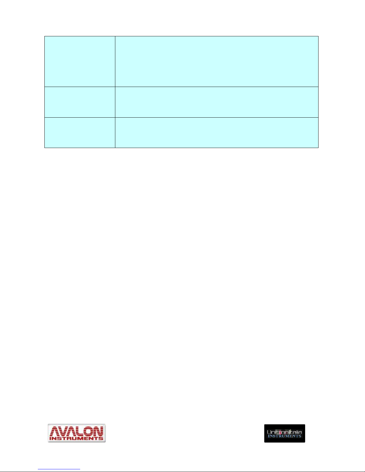
• On the ASCOM panel below (Figure 4.13) chose the ASCOM driver by clicking on
“Select” button.
Figure 4.13 – ASCOM telescope interface
• The classic “ASCOM Telescope Chooser” panel will open. Select the
AvalonStarGo.NET driver in the dropdown menu and then click “OK”.
Once the Avalon ASCOM driver has been accepted, press the “Connect” button on the
ASCOM telescope interface panel of Figure 4.13.
At this point the telescope will be under ASCOM control and it may be driven by CdC as
well as other ASCOM compatible programs like Astrotortilla, PHD Guiding or Sequence
Generator Pro (SGP), for example.
Page 45

_____________________________________________________________________
© All Rights reserved! ! !
!
45!
The movements of the mount executed through CdC will be transmitted and shown in
StarGO and those done in StarGO will have a feedback, also shown, on the planetarium
display.
All the instructions described are valid also for the use of the mount in Alt-Az mode. In this
case it is useful to select the check-box on the left of the AZ-ALT display windows in the
ASCOM Telescope interface, to have also the alt-Az coordinates shown in the panel.
4.8 Using the StarGO with a wireless connection.
One of the more innovative features of the Avalon Mount and the StarGO Control System is
the capability to manage the connection with the user devices in a “wireless” manner, using
the Bluetooth or Wifi standards depending on the choose made at the order time. Taking
advantage of this function requires a device (computer, smartphone, tablet) which has
wireless capability and software suitable to interact with the mount using this technology.
The following combinations of devices and software have been tested to date:
1. PC Windows (XP, 7 and 8) / TheSkyX Pro
2. MACOSX (10.9.4) / TheSkyX Pro
3. MACOSX (10.9.4) / Sky Safari Pro
4. Samsung Galaxy Tab S (Android) / Sky Safari Pro
5. Samsung Galaxy Note 2 and 8 (Android) / Sky Safari Pro
6. Samsung Galaxy 5S (Android) / Sky Safari Pro
7. Apple iPhone and iPad /Sky Safari Pro
Other Device/Software combinations will be added once further compatibility tests, now
being conducted, have been successfully completed.
The use of TheSkyX Pro and Sky Safari Pro makes the Avalon mounts also operable on the
Mac Operating System (MACOSX).
Furthermore, using portable devices the above 4 to 7 combinations allows mounts equipped
with StarGO to be operated even without the use of a PC (or a Mac).
The procedures for the StarGO control system connections with a Windows PC via
Bluetooth and WiFi are described in the section 4.8.1 through 4.8.2.
The use of the StarGO hardware with SkySafari or TheSkyX on MacOSX and with
SkySafari on portable devices will be described in section 5.
4.8.1 Bluetooth pairing the StarGO with a Windows PC
The use of a Bluetooth link for the data transmission requires the "pairing" with a Bluetooth
capable device. For example, on a PC with the newest Windows 10 operating system,
which is fully compatible with StarGO, follow these steps:
Under the Windows “Start” button select “Settings”. The following panel will open:
Page 46

_____________________________________________________________________
© All Rights reserved! ! !
!
46!
Select Devices (green oval) to open the related panel as follows:
In this panel select the Bluetooth item and then the StarGO device. In our example it is
named M-zero. However other Avalon Instruments product names are possible and are
easily identifiable. A subpanel will open:
Page 47

_____________________________________________________________________
© All Rights reserved! ! !
!
47!
In this panel insert the passcode for the StarGO. Normally it is 1234. If different, the correct
one will be provided together with StarGO documentation.
The PC is now connected to the StarGO. After the Bluetooth connection is secured, all other
control operations are absolutely identical to those performed with a USB connection.
4.8.2 Bluetooth pairing the StarGO with a Macintosh
The procedure to pair a Mac with the StarGO via Bluetooth is very similar to that just
described. On the Mac follow these steps:
Open System Preference window and select Bluetooth. The following panel will open:
The already connected devices will be shown in the window and the rotating wheel in the
upper right side will indicate that the Mac is searching other available devices. Powering on
the StarGO the Mac will discover it in several seconds and the following will appear:
Page 48

_____________________________________________________________________
© All Rights reserved! ! !
!
48!
In this click "Pair" in correspondence with the discovered StarGO Bluetooth device. A
subpanel will open:
Insert the StarGO code. It is, normally, 1234. If different, the correct one will be provided
with StarGO documentation. After few seconds the pairing will be established as shown in
this screenshot:
Page 49

_____________________________________________________________________
© All Rights reserved! ! !
!
49!
The Mac is now connected to the StarGO.
4.8.3 Connect the StarGO to a Windows PC via WiFi
The use of a WiFi link for the data transmission between the PC and StarGO requires that
PC is connected to the WiFi network that is created by the WiFi version of the StarGO
hardware. On a PC with the newest Windows 10 operating system, which is fully compatible
with StarGO, follow these steps:
Power on the StarGO.
Click the WiFi icon among the windows toolbar icons.
Among the available WiFi network names chose “StarGO-WiFi”, If it is the first time the
connection is attempted, the insertion of the password is required. Type “avalon1234” or
whatever password Avalon Instruments has provided with the software. Wait few seconds
until the connection is established.
The StarGO SW is now wireless connected to the PC and the mount is ready to be
operated.
4.8.4 Connect the StarGO to a Macintosh via WiFi
The use of a WiFi link for the data transmission between the Mac and the StarGO requires
that Mac is connected to the WiFi network that is created by the WiFi version of the StarGO
hardware. On the Mac, follow these steps:
Power on the StarGO.
Click the WiFi icon among the top toolbar icons.
In the dropdown windows that appears chose StarGO-WIFI:
Page 50

_____________________________________________________________________
© All Rights reserved! ! !
!
50!
If it is the first time the connection is attempted, the insertion of the password is required.
Type “avalon1234” or whatever password Avalon Instruments has provided with the
software. Wait few seconds until the connection is established.
The StarGO SW is now wireless connected to the Mac and the mount is ready to be
operated trought compatible software such as The SkyX and SkySafari..
Page 51

_____________________________________________________________________
© All Rights reserved! ! !
!
51!
5. StarGo and SkySafari
The StarGO Control System may be easily operated by the SkySafari application running on
Macintosh computers and Android and iOS based tablets and smartphones.
As seen before, Apple mobile devices (iPad and iPhone) can be connected only via WiFi,
whereas Android devices can be connected with both Bluetooth and WiFi.
Windows PC cannot be used because SkySafari is not yet available for this operating
system.
The Mac connections to the StarGO via Bluetooth and WiFi have been described in the
previous sections 4.8.2 and 4.8.4 respectively.
The Android connection via Bluetooth is described in the following sections 5.1.1 and 5.1.2
respectively whereas the connection of iOS devices is described in section 5.1.3.
Once the connection has been established the operational mode is similar for all the
considered devices.
5.1 Mobile device Bluetooth and Wi-Fi connection.
5.1.1 Bluetooth pairing the StarGO with an Android tablet or smartphone
This operation can be easily done following these simple steps (the figures can be slightly
different in various Android devices):
1. Select Setting in the device main screen and, when window opens, select
Bluetooth in “Wireless and network” section. The screen will look as follows:
2. Press “M-zero” or any other mount name detected under “Available devices”.
After a few seconds a small window will arise requiring the pairing PIN:
3. Enter the PIN provided by Avalon (again, usually 1234) and press OK. After few
seconds the device will be paired (see next screenshot) with the StarGO. The
mount will then be ready to be controlled by the device.
Page 52

_____________________________________________________________________
© All Rights reserved! ! !
!
52!
5.1.2 Wi-Fi connection of StarGO with an iPad or iPhone
This operation can be easily done following these simple steps:
1. Select Settings in the device main screen and, when window opens, select Wi-Fi.
2. Choose “StarGO-WIFI” in the “CHOOSE A NETWORK” section.
3. After a few seconds the StarGO-WiFi network will appear as selected one on the
side of Wi-Fi icon:
Page 53

_____________________________________________________________________
© All Rights reserved! ! !
!
53!
4. At the first connection, a password is required. Type “avalon1234” or whatever
password Avalon Instruments has provided with the software.
5.1.3 Wi-Fi connection of StarGO with an Android tablet or smartphone
This operation can be easily done following these simple steps (the figures can be slightly
different in various Android devices):
1. Select Setting in the device main screen and, when window opens, select Wi-Fi in
“Wireless and network” section. The screen will look as follows:
2. Choose “StarGO-WIFI” in the “Wi-Fi NETWORK” section.
3. At the first connection, a password is required. Type “avalon1234” or whatever
password Avalon Instruments has provided with the software.
Page 54

_____________________________________________________________________
© All Rights reserved! ! !
!
54!
4. After few seconds the connection is established as shown in the oval:
5.2 Sky Safari setup
Before using SkySafari with Avalon mounts it is necessary to set some important
parameters in the program setup page. SkySafari is provided with plenty of parameters to
set, mostly dedicated to the program display characteristics. This section of the manual will
deal only with those parameters which are necessary for the Avalon mount control. Read
the SkySafari manual to set all other parameters
( http://www.southernstars.com/support/manual/index.htm ).
1. Launch the SkySafari (version 4 or above) on the device. The program will open
with the following screen:
Page 55

_____________________________________________________________________
© All Rights reserved! ! !
!
55!
2. Press the Settings icon on the bottom bar. A screen will appear with a long list of
all the parameters to be set. First of all open the “Time and Date Setting” arriving
at the following screen. If the device date and time shown on the screen are
correct, simply check the “Use current Time” box. Otherwise set the current date
and time as required. When done click over the X in the upper right corner to save
and exit the current page.
3. Open the “Location Settings” page. In this page insert the name and the
geographic coordinates of the site. Also insert also the approximate elevation and
the Standard Time Zone as required. It is most important that the date, time and
location settings are exactly the same as those saved in the StarGO settings to
avoid any conflict. When finished, press “Save User-defined Location” for future
use.
Page 56

_____________________________________________________________________
© All Rights reserved! ! !
!
56!
4. The last but very important set of parameters is the “Scope Setup Settings”. The
instructions in this page will allow you to insert the telescope and mount type
(Meade LX-200 Classic and Equatorial GOTO or Alt-Az as needed, respectively,
for the Avalon mounts). In the Android device the Bluetooth as communication
standard is chosen as shown in the following screenshot:
In case of connection via Wi-Fi, an IP Address of 10.0.0.1 and a Port Number
4030 shall be typed for Macintosh and iOS devices, as shown in the following
screen:
Page 57

_____________________________________________________________________
© All Rights reserved! ! !
!
57!
5.3 SkySafari Connection and alignment
1. Once all the operations described in the previous sections have been completed, it
is possible to start moving the telescope using SkySafari. The first action to
perform is to manually put the telescope in the “Home” position, i.e. with the
counterweights pointing the down (CWD) direction and the telescope pointing
toward the North Celestial Pole for the mount in Equatorial Mode (see next figure
to the left) or the telescope pointing toward the North Celestial Pole regardless the
mount orientation but well levelled.
Page 58

_____________________________________________________________________
© All Rights reserved! ! !
!
58!
!! !
! Equatorial mode Polar Alignment Alt-Az mode Polar Alignment
Then connect the mount to the device by pressing the “Connect” button at the
bottom of the planetarium application screen as shown in Figure 5.1 below.
2. After few seconds the “Connect” button will change to read “Disconnect”. A chime
will sound and the telescope FOV pointer position (CCD or eyepiece) on the
SkySafari screen will appear exactly at coordinates RA=0, DEC=0 if the mount is
in Equatorial mode or with the coordinates of the North Pole if the mount is in AltAz mode. The commands to the right of “Disconnect”, i.e. “GoTo”, “Align” and
“Lock” will become active .
3. To correctly start the navigation operations in Equatorial Mode, it is necessary to
transmit to the mount the coordinates related to the “Home” position because, as
seen, when the mount is powered on, StarGo is unaware of these coordinates.
In case of Equatorial mode, therefore, after the initial connection with SkySafari,
the very first sync action to be performed is to transmit to the StarGO the point
where the mount is really pointing at that moment (i.e. the Celestial Pole). This
operation consists of performing an initial sync, using the “Align” function of
SkySafari. Position the cursor on a star on the meridian and close to the southern
horizon, without moving the mount from its Home position. This is equivalent to
performing the “Sync Home Position” using the StarGO software as described in
section 4.2.5.
The following sequence of three SkySafari screenshots, taken with the mount in
equatorial mode, is useful to understand the event sequence and its results:
They were taken a) just after the connection has occurred (Figure 5.1), b) at the
moment of syncing to a near South Meridian star (Figure 5.2) and c) after the
“Align” function is carried out (representing the North Celestial Pole area, Figure
5.3).
Page 59

_____________________________________________________________________
© All Rights reserved! ! !
!
59!
Figure 5.1
The above illustration depicts, as described above, the SkySafari screen just after
the connection the telescope pointer is put exactly on the celestial coordinates
origins, i.e. RA=0 e DEC=0, as seen in the ovals 1 and 2 in Figure 5.1. The RA
indication in oval 2 differs slightly from the point 00, 00 due to the time elapsed
between the moment of the connection and that of the screenshot (38 seconds in
our example) because the telescope is not yet tracking.
!
Figure 5.2
The second phase in this sequence is the choice of any star very near to the
Meridian and to the Southern horizon. In this case the star is η Aql (see ovals 3
and 4 of figure 5.2). Note that the telescope is still in the initial position (oval 5).
Again it is possible to see a small difference in RA from the point 0,0 due to the
Page 60

_____________________________________________________________________
© All Rights reserved! ! !
!
60!
time lapse. At this point is possible to tap the “Align” command on the “Telescope
Bar”.
!
Figure 5.3
Issuing the Align command causes the movement of the telescope pointer to the
North Celestial Pole (see oval 7) at the correct RA and DEC “Home” position (see
oval 8) where the mount is indeed pointing. This information is sent to the StarGO.
This is also the initial position of the telescope in case of Alt-Az mode. From this
moment the movement of the telescope is synchronous with that of SkySafari.
4. Now the telescope can be operated using the available commands and the
direction control on the side of SkySafari screen below. On the left the RA direction
controls and on the right the DEC controls. The telescope movement rate can be
adjusted using the yellow “Rate” slide bar above the telescope controls.
Page 61

_____________________________________________________________________
© All Rights reserved! ! !
!
61!
5.4 StarGO and SkySafari in Alt-Azimuth mode via Bluetooth or WiFi
When the mount is used in Alt-Azimuth mode, almost exclusively for visual observations, it
is possible to operate it using an Android Tablet (or Smartphone) equipped with the
SkySafari application, without the need of a PC connection.
However, as described in section 4, it is first necessary to set up the Alt-Azimuth operation
mode using the StarGO software on the PC (or, if Bluetooth is available, on the Android
device using StarGO-BT – See chapter 6). This choice is done only one time and needs to
be repeated only in case of another change of operating mode.
All the Bluetooth pairing and Wi-Fi connection and SkySafari setup are the same as
described in the sections from 5.1 to 5.3. The only difference is that when choosing the
mount, the Alt-Azimuth mode shall be chosen instead of the Equatorial in the Safari setup
page.
The first operation to be performed on the field is to put the telescope in the Home position
after having scrupulously levelled the tripod. The “Home” position, for the Alt-Azimuth mode,
corresponds to pointing the telescope in the direction of the Celestial North Pole. Since the
polar-scope is not available in this mode, this operation is not trivial. A certain degree of
error is acceptable and will be compensated in the following alignment by placing Polaris,
the North Star, in the center of the telescope FOV. With the telescope in this position,
perform a Goto to a well known bright star, centring it in the eyepiece field of view using the
StarGO keypad or the directional commands of SkySafari. Using an eyepiece equipped
with a cross-hair reticle would improve the accuracy. When the star is well centred, the sync
command to this star will be issued using the “Align” button of SkySafari. At this point the
telescope will have performed a “One Star” alignment. The precision of the succeeding Gotos will be determined by the precision of the previous operations, especially by how
accurately the tripod plate is levelled.
NOTE: When the “Use Multi-Star Model” is checked in the StarGO (see section 4.2.5,
fig. 4.6) and therefore the multi-star modeling is enabled, the first and each
successive sync, up to 24, contributes to build the model. To maintain the StarGO in
Multi-Star Model enabled status it is necessary to check it during the last
computerized section, switching off the mount in this status.
!
Page 62

_____________________________________________________________________
© All Rights reserved! ! !
!
62!
6. Mount Control with StarGO-BT for Android
Avalon Instruments has developed an application, called StarGO-BT, capable of controlling
Avalon mounts by means of Android based smartphones and tablets with Bluetooth
connection capability.
The purpose of this application is to provide a commonly available alternative to the keypad
for controlling the mount with the advantages of a wireless connection and a more user
friendly interface. Moreover the application enables setting of a number of mount
parameters that are not settable with the keypad or are settable a more simplified manner
than with the keypad. These settings are unidirectional, same as with the keypad.
This application is part of the software package provided with the StarGO control system. At
the present time, this application cannot be downloaded from the usual Google Play Store,
but it must be directly installed in the device by the user. The following sections describe the
instructions for the app installation and use.
The starting point for the installation is the establishment of communication between the
Android device and StarGO hardware. This operation has been already described in section
5.1.
6.1 Application Installation
The app is contained in a single file named StarGo-BT.x.y.z.apk, where x.y.z represent the
software version. This program, like all other Avalon Instruments, software, drivers and
related manuals, are continuously improved and increased in functionality. Thus, the version
numbers will vary quite often.
To install the application it is necessary to upload the file mentioned above in the device.
This can be done in several ways, depending on the type and brand of the device. For
example, the Samsung device can use the Kies application to copy the file in whatever
position of the main memory or external memory (if available).
Once the files is installed in the device, it is possible to access it using the file browser
application (for example “Archive” of the Samsung devices) and to launch it.
Page 63

_____________________________________________________________________
© All Rights reserved! ! !
!
63!
When the file is selected, the process of app installation in the device will start. It is very
probable that, at the start of this process, the installer will inform you that it is not possible to
continue because the installation of applications not coming from the Play Store is not
allowed. To continue it will be necessary to open the Setup Window of the device and (at
least temporarily) enable the installation of applications from unknown sources under the
option “Unknown Sources” within the “Security” menu.
Page 64

_____________________________________________________________________
© All Rights reserved! ! !
!
64!
6.2 Application Use.
Like all Android apps, StarGO-BT is launched by touching the icon created during
the installation process. The initial screen will show the list of all external devices, capable
of Bluetooth connectivity, associated with the Android device. To establish a logical
connection between the app and the StarGO hardware please select the correct option from
the list, in our case StarGO. This action will highlight the “Connect” button through which the
connection is established.
Once the connection is established, the app will show the main screen through which all the
control operations on the StarGO can be performed. The screen slides vertically to allow the
access to the various setup functions
The application screen looks quite familiar because it is dominated by the cross of
directional keys and the central STOP key that have the same functions of the StarGO
software keys.
The speed of the movements will be set with the four speed setting keys corresponding to
those of the StarGO PC software (Guide, Center, Find and Slew).
Page 65

_____________________________________________________________________
© All Rights reserved! ! !
!
65!
6.3 Application setup
Sliding down, the screen will be replaced with a group of command setting labels for
controlling the mount in Bluetooth:
The first of the available commands is the “TRACKING SPEED” label. Touching the label
opens the string of the buttons to select the desired tracking speed: Sidereal, Solar, Moon
and Earth. The latter is used for taking terrestrial time lapse pictures.
The MISCELLANEOUS label controls the auxiliary functions (i.e. focuser or others) which
will appear. There will be a pair of opposing arrows to move connected devices in opposite
directions. The central button will control Aux 1 and Aux 2 devices or the Polarscope LED
intensity.
Page 66

_____________________________________________________________________
© All Rights reserved! ! !
!
66!
By touching the “MOUNT SETTING” label a set of commands appears to reverse the
motion direction of the RA and/or the DEC motors, to chose among the M-zero, M-uno and
Linear mounts, and to select the operational mode between Alt-Azimuth and Equatorial
(GEM).
Page 67

_____________________________________________________________________
© All Rights reserved! ! !
!
67!
The next label, “SITE POSITION” will pop up the set of commands to introduce the
observation site coordinates and to show their values. The commands are self explanatory.
Other commands allows to get the site position from the tablet or smartphone internal GPS,
if any and to send the acquired coordinates to the StarGO if active.
Note: When using the Sky Safari application, it is necessary that both applications
(StarGO-BT and Sky Safari) have identical geographic coordinates or unpredictable
mount behaviours could ensue. The correct configuration is automatically attained in
both applications when the Android device’s internal GPS is used to obtain Latitude
and Longitude. If, for any reason, custom values for coordinates are used in either of
the two applications, exactly the same values must be manually inserted in the other
application.
The last label, “ALIGNMENT,” enables the actual Local Standard Time (LST) value to be
read and the syncing to Home Position to be reached. The “Sync Home Position” button
allows the mount to synchronize with the home position, as done with the PC StarGO
software (see section 4.1.1, Page 19).
Page 68

_____________________________________________________________________
© All Rights reserved! ! !
!
68!
Page 69

_____________________________________________________________________
© All Rights reserved! ! !
!
69!
7. Firmware Updating – StarGoLoader
The first time StarGO is launched, after the software is updated, a check is performed to
verify if the firmware is compatible with the latest version of the software. If the check result
indicates incompatibility, the warning reported in figure 3.1 on page 22 will be shown. In this
case it is necessary to open the setup panel and to activate the firmware updating routine
by pressing the Firmware Upload button (see figure 4.2, pag 25). This will cause the sudden
closure of StarGO and the opening of the StarGO Loader application window:
NOTE: The firmware to be installed is provided by Avalon Instruments pre-set with
generic parameters so that the existing settings will not be lost. For that reason, it is
recommended to save the “Mount Configuration File” before completing the updating
operation, as explained in section 4.2.1. When the updating is completed, you should
re-load the saved file as explained in the same section.
The following are the step by step operations to be performed to update the firmware:
1. Press Load button to open the loading window where the firmware file is chosen.
2. Choose the most recently updated file with .af2 extension among those shown in the
windows. Press Open to confirm. The StarGo loader window will show the name of
the chosen file. Verify that it is correct and then press Start to begin the uploading
process.
Page 70

_____________________________________________________________________
© All Rights reserved! ! !
!
70!
3. A warning window will appear informing the user that the uploading utility will set the
default configuration, inviting to save the present configuration if necessary (see the
NOTE above).
4. If everything is correct, press the Yes button. The uploading will start and its progress
will be indicated by the green bar.
Page 71

_____________________________________________________________________
© All Rights reserved! ! !
!
71!
5. When the process is completed, the successful uploading is announced. Press
Close button to exit the application.
6. Restart StarGO and connect it. A warning will appear informing that the mount is not
configured asking to reload the Mount Configuration File previously saved:
7. Pressing OK will cause the opening of the loading windows for the available
configuration files.
Page 72

_____________________________________________________________________
© All Rights reserved! ! !
!
72!
8. Choose the correct configuration file. When loading is finished, the StarGO will be
ready to work with the newly installed firmware and the correct configuration,
NOTE : The uploader is able to restart its function, even after an accidental
interruption of the uploading process, without any risk of StarGO hardware damage.
In this case simply restart the operations from the beginning.
Page 73

_____________________________________________________________________
© All Rights reserved! ! !
!
73!
APPENDIX
X-SOLVER TOOL
Plate Solve and Modelling
A1.0 Introdu ction
The Avalon Instrument Software package, starting from StarGO version 5.1.42 and
Firmware version 5.1.6, includes a sophisticated and powerful tool to perform an automatic
telescope Multi Star Alignment Model (up to 24 stars), called X-Solver. It is a Plate-Solving
program, based on Astronomy.net engine that allow to carry out blind solving of whatever
area of the sky where the telescope is pointing. In addition it allows choosing up to 24 point
in the sky and commands the telescope to sequentially perform GOTOs to the selected
points, taking images and then plate solving them. The information acquired is used to build
a sky model for the telescope that is used by the StarGO program and by all other ASCOM
connected programs, such as planetarium, to perform very precise pointing. The labels
under the main coordinate display indicate the presence of a multi star model in the StarGO.
A1.1 GUI description
X-Solver is invoked by clicking on its icon placed on the desktop during Avalon Instrument
software installation, obtaining the following main window:
Fig.1 – X-Solver GUI before device’s connection
Page 74

_____________________________________________________________________
© All Rights reserved! ! !
!
74!
Once opened, the X-solve windows top header will inform the user, in addition to the
program version, on the type of Plate-Solving chosen and the image sampling of the system
used.
Before the device connection the Main windows has the aspect here described. It is
subdivided in two large areas. The first is mostly occupied by the frame containing the
picture to be solved and, on the top, a set of menu items. The first five menus are related to
the image acquisition and the last to the Polar Alignment function. Below the picture, the
pieces of information related to the progress of the solving process (time to solve, average
time to solve and total solving time) are shown.
The smaller frame on the right side has three tabs: PLATE SOLVE, MODEL and SETTING.
The first tab, which is selected at the devices connection, allows the insertion of some
shooting parameters, the starting of the acquisition and solving process and, finally the
obtained results and the check box to perform an automatic “Solve and Target Center”
automatic action.
The second tab MODEL, as well as the third SETTING, is not active at the X-Solver starting.
MODEL tab contains all command to perform the automatic modeling of the sky based on a
N up to 24 star alignment.
The SETTING tab allows the insertion of the system and the plate solve algorithm
parameters.
The status bar on the bottom of the main window is subdivided in two lines. Before the
connection it shows only that the mount is in a NOT TRACKING status and all other
information and check boxes are blackened.
Page 75

_____________________________________________________________________
© All Rights reserved! ! !
!
75!
A2.0 X-Solver Operation
A2.1 X-Solver connection
The first operation to be performed after the X-Solver opening is the connection to the CCD
used for the solving and the StarGO mount involved. Press the CONNECT button and the
connection window will popup:
Fig. A2 – ASCOM device connection windows
If we want to use the X-Solver to plate solving an existing image, it is necessary to check
the “Use Image File acquisition” checkbox for enabling the manual image loading.
In this case, checking the mentioned checkbox will cause the right panel of the main window
to change as follows, allowing to load an existing image from the PC By pressing the LOAD
IMAGE button.
Page 76

_____________________________________________________________________
© All Rights reserved! ! !
!
76!
Once the chosen image is loaded the main windows will show with a suitable stretching
level to allow its view.
On the left of the image there are two sliders to be used to enhance the image view. The
upper regulates the Brightness and the lower one regulates the contrast of the acquired
image.
Note that under the LOAD IMAGE button there is the “Sync mount with solved image”
checkbox. Selecting it allow the mount to be aligned with the image shown.
For a normal on-line use, clicking on the CAMERA CHOOSER button with the “Use Image
File acquisition” check box unselected, will invoke the ASCOM camera chooser. This is a
standard chooser that through the dropdown menu allows the selection of our camera
among those listed. In the example windows below we choose the ASI camera.
Page 77

_____________________________________________________________________
© All Rights reserved! ! !
!
77!
If this is the first time that camera is selected a warning will inform the user that before to go
on it is necessary to set some camera parameter by pressing the Properties button. If this is
the case a setting panel, similar to the following, will appear.
It is clear that it is only an example linked to the chosen camera. Other cameras will use
different setup panel.
Once introduced the needed parameters (very often the default ones are ok) press Ok and
Ok again in the Chooser panel.
It is evident in Fig. A2 that the StarGO is pre-selected and no other choices are possible.
The gear buttons will allow in every moment to invoke the setup panel if different setting are
needed to optimize the shooting and solving operations.
At this point it is possible to connect the devices, camera and mount, simply by pressing the
plug buttons. After the connection is established the button will change the color from red to
green. At this point it is possible to close the chooser window.
A2.2 The X-solver as a simple Plate Solver.
The X-Solver application may be used to perform plate solving for precise telescope
synchronization in case an advanced modeling with many stars is not strictly required. This
is the case of a mobile telescope used for few target shooting in a single night before to
move it for future use in other locations. In such a case it is important to speedup the
pointing operations for the few objects to take.
SETUP:
The first operation to be performed just after the device connection is the parameters setting
for the plate solving. This is done through the SETTINGS tab of the main window.
Page 78

_____________________________________________________________________
© All Rights reserved! ! !
!
78!
The first setting to do is the choice of the method to be executed for the plate solving. The
only difference between the two methods is that the Astrometry.Net Blind Solver requires
the access to the Internet whereas the Local Plate Solver uses a local data base. If Internet
is available, it is preferable to use the first method. If it is not available the second method is
the only possible one. In this case be sure that a correct database has been installed in the
computer and that the data base indexes, which depends by the characteristics of the
photographic setup, have been also installed at home before the system is used outdoor.
To install the local plate solver engine, visit the site addressed in the “Go to the instruction
Page” link. In this page there is the link to the ans-setup-x.yz.exe installer and very detailed
instructions for its installation. Follow also the instructions needed to download the proper
database indexes depending on the used instrumentation FOVs.
If Local Plate Solve is chosen it is also needed to introduce the telescope focal length, the
CCD pixel size in micron and the Radius of the search range expressed in degrees. This
last parameter is very important because from one side it guarantees the solve success (the
higher the better) but from the other side it increases the number of the needed indexes and
the calculation time (the lower the better). A compromise should be done based on his own
experience.
The last three check box of the panel have the following explanation:
Old QHY/MZ Cameras: this choice optimizes the results using the ASCOM version 1 old
QHY cameras.
Color Camera Boost: this setting improves the performance of One Shot Color cameras.
Save solved image: this can be useful if there is the intention to use the image for any
further purpose.
Before to start the shooting for the plate solving it is necessary to set the shooting
parameters. This is done in the first panel PLATE SOLVE. We may note that, after the
Page 79

_____________________________________________________________________
© All Rights reserved! ! !
!
79!
connection with the devices this panel is changed. The text characters, just after the
application start as in Figure 1, are black and barely readable and no button is active. Now
they are white and well visible and the ACQUIRE & SOLVE button is now active.
The operations to be performed in this panel are essentially two:
The Exposure Time choice in seconds, depending on the scope aperture and the camera
QE, shall be experimentally determined (usually start with 5 sec and increase or decrease
on the base of the results).
The CCD binning value allows adjacent pixels to be combined obtaining benefits in terms of
faster readout speeds and improved signal to noise ratios albeit at the expense of reduced
spatial resolution. The chosen value depends on the CCD characteristics.
The three check boxes under the target coordinates allow performing some fine-tuning
operations:
The first, “SOLVE After GOTO”, enables the start of the solving process (image shooting
and solving) immediately after the GOTO, without any operator manual request.
The second, “Sync After GOTO”, enables the syncing of the mount to the center of the
target just resolved.
The third check box, “RECENTER After GOTO”, allows the telescope to move again to the
original target coordinates to exactly center the target.
Below the button there is another check box enabling the syncing of the mount to the loaded
image solved position.
OPERATION:
The use of the X-Solver application for performing a very quick and precise centering of the
chosen target is quite simple:
Page 80

_____________________________________________________________________
© All Rights reserved! ! !
!
80!
1. Put the telescope in Home position (CWD) and perform a “Sync Home Position” using
the ALIGN tab of the StarGO setup panel.
2. Perform the GOTO to the chosen target using the StarGO internal data base or any
other planetary program connected to the telescope and wait it reaches the stop. You
will note that at this point the Target RA and DEC indication on the “PLATE SOLVE”
panel are now populated with a value related to the target.
3. Take a single shot, using the SHOT button in the menu bar above the image screen, to
verify if the exposition time and the binning chosen are suitable to a good plate solving.
If very few stars appear increase the exposition. If to many stars are present, decreases
it.
4. Now there are two options: if you want just to verify how far is your target from where
the telescope is pointing (your image), leave the “SOLVE and Center After GOTO”
check box unchecked and press the “ACQUIRE & SOLVE” button. The X-Solve will take
an image and will start performing the calculation. After a number of seconds
(depending on several factors) the solution will appear under the form of telescope
coordinates in the SOLVED RA and DEC below the “ACQUIRE & SOLVE” button. The
X-Solver windows will look like:
Note the solver time given below the image and the solved RA and Dec that are few
arcsec different from those of the go to target
If you want the telescope automatically sync to the target after the Plate Solve
succeeded, using the above calculated RA and Dec offsets, check the “Sync mount with
solved image” check box before initiate the acquisition and solving process. In this case,
after the solving succeeded, the telescope will be automatically aligned.
Page 81

_____________________________________________________________________
© All Rights reserved! ! !
!
81!
5. You may repeat the point 4 if deemed necessary to improve the pointing. Our
experience is that, after the first attempt, the target is within few arcsec.
A2.3 The X-Solver as a tool to perform N up to 24 star alignment modeling
The X-Solver is an as powerful as easy tool to built a sky model based on the alignment of a
large number of stars (up to 24) leaving the classical 3-star alignment as a thing of the past.
Before performing the modeling it is required to carry out a good polar alignment.
The modeling function is particularly useful in fixed observatory installations, however for
the speed of its execution, it may be used also for mobile installations, especially for visual
observation (after a short period of CCD use at the very beginning of the session).
The instrumentation setup is exactly the same of the simple plate solving operation already
described in the previous sections.
The operations for the sky modeling are fully executed using the command in the MODEL
tab of the X-Solver GUI.
The following is the detailed explanation of each command button.
1. The most important button of the panel is the “SKY MODEL” big button on the bottom
right, that with the Big Dipper inside. Clicking on it will invoke the SKY-MODEL window:
Page 82

_____________________________________________________________________
© All Rights reserved! ! !
!
82!
This window shows a 2D representation of the Northern Hemisphere sky in altazimuthal coordinates. The Azimuth is in the x-axis and the Altitude in the y-axis. The
yellow circle indicates the current telescope position. This diagram shall be populated
by the operator with a number of points by clicking the mouse (up to 24), taking into
consideration for their position several factors such as the real Horizon, the presence of
obstacles as building or trees, the presence of the moon, the season, etc.
2. The large circle with a number inside, located on the left of the “SKY MODEL” button
indicates the progress of the operation. The number shows the time spent in the model
construction.
3. Directory: This command, placed on the top of the frame, allows defining the folder in
which to save the built models or the upload the existing models formerly saved. It
causes only the opening of the classical explorer windows for choosing a file or a folder.
The name of the selected folder will appear in the text box on the right of the command.
4. The Model Name text box is used to give the name to a new model. It also shows the
name of the model presently in memory.
5. LOAD SAVED MODEL FROM FILE button allows performing what is written. By clicking
on it a file explorer windows will appear opened in the directory previously selected.
In the above figure example we have selected the model directory and the file
Matrix_4x4.PMF (this is the extension of the Pointing Model File) containing a formerly
created model of 8 stars. The blue points in the sky map represent the stars chosen for
the model creation.
Page 83

_____________________________________________________________________
© All Rights reserved! ! !
!
83!
6. CLEAR POINT ON SKYMODEL. Even this command does what is written inside: it
deletes unwanted point away from the formerly created model or from the presently
model under construction.
7. BEGIN SEQUENCE button starts the sequence. Move the telescope to the first point,
takes a shot and perform the plate solving, insert the determined coordinates in the
model and move the telescope to the second point and….so on. After a successful
solving the point color changes to green. If the solving has failed the color will be red. At
the end of the sequence the model is ready in memory.
8. SEND MODEL TO STARGO. Clicking on this button the model just built or the model
just loaded from file is sent to the StarGO. The success of this action will be shown on
the StarGO GUI, with the indication placed below the large coordinate display as in this
illustration. Before the model is sent to the StarGO the label says “0/24 Star Align.”
Whereas after the model is entered into StarGO it says “8/24 Star Align” to inform the
operator that the model is in action.
Before the Model is
sent to the StarGO
After the Model has
been sent to the
StarGO
IMPORTANT NOTE: The model just build is accepted by the mount only if the “Use
Multi-Star Model” check box, described in section 4.2.5, figure 4.6, has been selected.
Furthermore the model sent is valid only if no synced points are in the StarGO
memory. Therefore, before sending the model, be sure the StarGO memory has ben
cleaned of previous alignment attempts. Furthermore, after the model has been
loaded to the StarGO, additional Sync operations, performed with X-Solver or inside
the StarGO system, will increase the number of stars and the model accuracy will
improve.
Page 84

_____________________________________________________________________
© All Rights reserved! ! !
!
84!
A2.4 Image management
Some of the commands in the string of buttons located on the top of the images frame are
useful to manage the image itself and to optimize target framing in addition to allow a
preliminary focusing.!!
!
The first two commands of the string have been already described in the previous sections.
The next two are those needed to manage the acquired image.
The LIVE VIEW command start the live view function on the base of the shooting
parameters defined in the PLATE SOLVE tab. During Live View execution it is possible to
use the telescope movement commands to better framing the object to be shot and to reach
or improve the image focus before to use more dedicated manual or automatic focusing
tools.
The CROSSHAIR command adds a crosshair to the picture to help the centering of stars,
especially in the phase of manual n/24 star alignment process:
Page 85

_____________________________________________________________________
© All Rights reserved! ! !
!
85!
The ABORT button will immediately stop the operation of acquisition and/or solving process
under execution.
A zoom tool is also provided by clicking over the magnifier symbol placed on the top left of
the main window image. This action will cause a zoom window to open as follows:
The magnifying ratio can be regulated as needed using the slider placed in the left upper
side of the image.
A2.5. XSolver as a tool to perform precise Polar Alignment
Last but not least is the Polar Alignment function allowed by XSolver. Clicking on the last
button “P. ALIGN” of the main window menu will invoke the auxiliary window to perform the
measurement of the degree of mount alignment to the Pole, allowing a quicker and precise
refinement of the alignment.
The Polar Alignment window has the following aspect:
Page 86

_____________________________________________________________________
© All Rights reserved! ! !
!
86!
the upper frame of the window shows the present pointing coordinates in RA and DEC. In
the mean frame it is possible to choose the altitude over the horizon at which to take the
images necessary to perform the evaluation of the azimuth polar error. This values should
be the lower possible taking into account the possible obstacle close to the horizon (and the
effect of the atmospheric refraction at lower altitudes). It is also needed to select what side
of the meridian (East or West) must be used. Even this choice shall be based on the local
horizon characteristics. Normally East is better in the first night hours whereas the West
side is preferable at the late night when East begins to become lighted.
By pressing the “START POLAR ALIGNMENT” button the mount, which has been well
aligned to the sky in advance, will move the telescope to the chosen side of the sky at the
selected altitude, to tale the first images. The XSolver will perform the due calculations to
estimate the Azimuth error.
After this phase the telescope will move to the South meridian where it will automatically
take another series of images and will perform further calculations.
At the end of this phase the calculated errors in both Altitude and Azimuth will be shown in
the lower frame of the Polar Alignment window. If the errors are acceptable the
photographic session can follow. Otherwise it will be necessary to move the mount AltAzimut knobs to try to compensate the errors. Then, with a process of successive
approximations, the error estimation is repeated until a sufficient degree of precision is
reached.
The time spent for this function will be shown in the black status bar at the bottom of the
window.
 Loading...