

Page 1
Musical Masterpieces
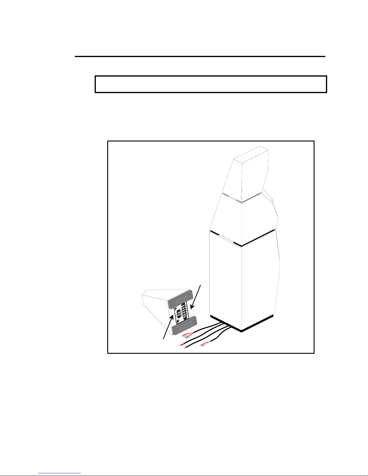
Serial Numbers ____________________
Handcrafted by:
_________________________________
_________________________________
_________________________________
_________________________________
This product is certified to meet the requirements of the European
Union (EU) Electromagnetic Compatibility (EMC) Directive
(89/336/EEC). Because the permanent magnets attached to the
loudspeaker drivers produce magnetic fields, it is recommended
that the product not be positioned in very close proximity to
computer monitors or television sets.
Page 2

Page 3

Table of Contents
1 Introduction .........................................................................................................................5
Overview .............................................................................................................5
1.1 Low Noise Floor.........................................................................................................6
1.2 Coherent Energy Transfer .......................................................................................7
1.3 The Active Reference System ................................................................................8
2 Unpacking Instructions.......................................................................................................9
Introduction ........................................................................................................9
Contents..............................................................................................................9
2.1 Room Preparation and Verification ......................................................................10
2.2 Crate and Box Placement for Unpacking ...........................................................11
2.3 Opening the Crates.................................................................................................12
2.3 Opening the Sub Amplifier Crates ........................................................................14
3 System Set-up......................................................................................................................15
Preparation .........................................................................................................15
Removing Apex Couplers from Set-up Blocks ...........................................15
Left / Right Channel Matching ........................................................................16
3.1 Lower Speaker Cabinet Set-up .............................................................................17
3.2 Upper Speaker Cabinet Set-up .............................................................................18
3.3 Crossover Cabinet Set-up ......................................................................................21
3.4 The Felt Anti-Diffraction Mask.................................................................................22
Orientation of the upper Felt Mask .................................................................22
3.5 Sub Amplifier Set-up ................................................................................................23
4 Wiring Instructions ...............................................................................................................24
Introduction ........................................................................................................24
4.1 Wiring and Field Interactions ..................................................................................25
Inductive field effects .......................................................................................25
4.2 Connecting Upper Speaker Cabinet to Crossover ............................................26
4.3 Connecting Speaker Cable to the Crossover ....................................................27
4.4 Connect Speaker Cable to your Amplifier ..........................................................28
4.4 Connecting Subwoofer to the Sub Amplifier ......................................................29
4.5 Connecting Preamplifier to the Amplifiers...........................................................30
1. Interconnect Y-cable at the preamplifier ................................................30
2. Two outputs at the preamplifier .................................................................30
3. Loop-Out from the Subwoofer Amplifier...................................................30
5 Break-in Period.................................................................................................................... 31
6 Subwoofer Amplifier ..........................................................................................................32
Design Principle…………………………………………………………………………32
7 Maximizing Performance
Break-in ................................................................................................................34
Separate Left / Right Amplifiers .......................................................................34
Felt Anti-diffraction Masks.................................................................................34
Room Treatment and System / Listener Position ...........................................35
Toe-In ...................................................................................................................35
Apex Couplers ................................................................................................35
First Reflection Points .........................................................................................36
Corner Treatment ..............................................................................................36
8 Care of Your Avalon Loudspeakers .................................................................................. 37
Cabinet ...............................................................................................................37
Crossover Cabinet .............................................................................................37
Felt Anti-diffraction Masks.................................................................................37
Drivers...................................................................................................................37
9 Warranty ...............................................................................................................................38
In the Event of a Problem .................................................................................38
Warranty Statement ..........................................................................................39
Page 4

10 Room Acoustics and Speaker Position ...........................................................................41
Introduction ........................................................................................................41
An Optical Analogy ..........................................................................................42
Basic Room Acoustics .......................................................................................42
10.1 Standing Waves .....................................................................................................43
10.2 Flutter Echo .............................................................................................................44
10.3 Early Reflections .....................................................................................................45
Avoiding Early Reflections ................................................................................46
Low Frequency Reflections ..............................................................................48
10.4 Bass reinforcement ................................................................................................49
10.5 Summary of Recommendations..........................................................................52
Flutter Echo and Standing Waves ...................................................................52
Early Reflections .................................................................................................53
Speaker Placement...........................................................................................53
10.6 A Listening Room Example ...................................................................................54
11 Listening Position ...............................................................................................................55
Path Length Symmetry......................................................................................55
Time Alignment ..................................................................................................55
Summary .............................................................................................................56
12 Accuracy of Bass Reproduction...................................................................................... 57
Introduction ........................................................................................................57
12.1 Sensitivity to Time-Related Information ..............................................................58
"Fast Bass" ............................................................................................................58
12.2 Measurements of Audio Equipment ...................................................................59
A Correlation with Amplifier Measurements ..................................................59
Loudspeaker Measurements ...........................................................................60
Designing for Accurate Bass Reproduction ..................................................61
12.3 Listening Qualities ..................................................................................................62
Frequency Response Effects ............................................................................62
Listening for Size Distortions...............................................................................62
Transient Response Effects ...............................................................................63
12.4 Active Subwoofer System .....................................................................................64
Anechoic Frequency Response vs. In-Room Frequency
Response .............................................................................................................64
Active Control of Bass Energy ..........................................................................64
13 Features..............................................................................................................................65
14 Specifications .....................................................................................................................66
Loudspeaker
Subwoofer Amplifier
.......................................................................................................66
..........................................................................................66
15 Notes ..................................................................................................................................67
Page 5

1 Introduction
Overview
The Avalon Acoustics Sentinel Active Reference System represents the
application of edge-of-the-art loudspeaker technology in every area of high
accuracy transducer development. New research in diaphragm materials,
magnetics, low-noise circuitry, resonance control, and temporal coherence,
never before employed in high energy transducers, redefines the boundaries
of music reproduction. The intent has been to create a full range transducer
capable of high-energy transfer that behaves like a small array with pointsource accuracy.
The Sentinel accomplishes this goal by lowering the noise floor and
eliminating stray energy, thereby preserving timing detail, transient accuracy,
natural instrumental timbre, and stage presentation while providing
transparency, clarity, and detailed focus up and down the frequency
spectrum. Powered by a dedicated high-energy subwoofer amplifier,
Sentinel actively controls and realistically renders low frequencies, down to 16
Hz, while maintaining transient accuracy and harmonic integrity. Truly an
Active Reference System, the Sentinel re-creates musical events in a manner
that is uncompromised and sonically neutral.
Your Sentinel is designed and built to the highest standards of workmanship
and performance. These standards are preserved through the test of time by
careful attention to component quality and meticulous testing of each unit
before leaving the factory. As a new owner of this Avalon Acoustics product,
you can be assured that you possess one of the few great loudspeakers the
audio industry has to offer.
5
Page 6

1.1 Low Noise Floor
A key element in achieving the sonic goals mentioned in the previous section
is significantly reducing the noise floor. The term "noise floor," in this discussion,
refers to the stray uncorrelated energy that is produced as an artifact by the
loudspeaker. This manifests itself in latent energy below the musical signal
and in deleterious phase noise. Both must be reduced to an absolute
minimum.
Through new proprietary technologies in the elements of the crossover
circuitry, the noise floor has been lowered by more than 25 dB over any
existing design. The low noise principle has also been applied to cabinet
design and construction, where new techniques in resonance control and
careful attention to diffraction and driver coupling effects further reduce
stray acoustic energy.
The overall sonic result is a three dimensional spatial presentation of the
instruments recorded within
background seems black and devoid of contaminating energy, while each
individual instrument breathes into the space in which it was recorded. Truly
low level details, such as wall reflections from the original recording site, are
clearly and concretely apparent. The entire recording environment, whether
natural or artificial, can now be transposed in toto to your listening room.
the context of their original environment. The
6
Page 7

1.2 Coherent Energy Transfer
Coherent energy is both an aspect of the absolute quantity of energy, and
also the speed
technologies in current transfer and in magnetic field energy storage within
the crossover maximizes the transient speed of the transducer, while
eliminating the ringing that can give recorded music a fatiguing and etched
quality.
Dynamic measurement techniques provide prediction of circuit behavior
under actual musical conditions. Through these techniques, current
saturation effects throughout the system are greatly reduced. Proper phasing
of elements within
technical developments, the level of inter-driver jitter (mis-timing between
drivers) can be virtually eliminated.
The sonic results of this technology are stable, tightly focused images that
retain their position and harmonic structure, regardless of input intensity
(provided, of course, that the chain of amplification is able to deliver the
quantity of energy required with great speed). The most apparent benefit of
coherent energy transfer is in the rendering of bass information. Low
frequencies are delivered with a clarity that reveals the subtle harmonic
structure of pipe organ and bass guitar passages, while precise timing
provides a coherent temporal structure throughout the frequency spectrum.
with which that energy begins and ends. Entirely new
the crossover circuitry is now achievable. With these new
7
Page 8

1.3 The Active Reference System
A definitive transducer project of this magnitude demands the holistic
integration of diverse design goals, including perfect phase response, critical
damping, and point source accuracy. In addition, horizontal dispersion must
be uniform across the frequency spectrum in order to generate a coherently
focused wavefront and minimize room interaction artifacts. The difficulty of
integrating all of these elements increases exponentially as the size of the
array grows larger. It is only through complex computer modeling, meticulous
physical and electrical alignment, and scores of hours of dedicated listening
that correct phase response, without restricting the frequency response, has
been achieved. The result is a transducer that is extremely revealing of
microphone placement and phasing techniques from the recording site. The
most subtle ambient information is clearly apparent. There is no exaggeration
of details over fundamental elements of the recording; context is always
clearly maintained.
These qualities are most apparent when using the Sentinel Active Reference
System as an evaluation tool. Amplifiers, for example, that were previously
thought to have similar sonic characteristics are now definitively separated by
their individual signatures. The system's smooth non-reactive impedance
response insures that the sound of an amplifier is not due to an interactive
effect, but is a true representation of its sonic fingerprint. By ameliorating
many of the technical shortcomings of all previous transducers, the music
lover moves closer to the performance and the intent of the artist. Similarly,
the critical evaluator now has a transparent window through which the
differences between the elements under test (e.g. amplifiers, cartridges, etc.)
can be clearly discerned.
8
Page 9

2 Unpacking Instructions
Introduction
Your Avalon Acoustics loudspeakers and sub amplifiers were shipped in seven
heavy-duty crates to ensure their safe arrival. It is recommended to save
these crates and boxes for possible future use. Due to the weight of the
system, the listening room floor structure must be extremely robust and
reliable.
WARNING: The Sentinel Active Reference System weighs over 1,100 pounds
(approximately 520 kg). You MUST evaluate and verify the integrity of the
intended listening room floor structure before bringing the crates into the
home.
In addition, it will require three persons to un-crate them and position them for
listening. Please arrange for your dealer and/or other friends to assist in this
project.
CAUTION: Three people are required for unpacking and set-up. To avoid
injury, do NOT attempt to unpack or set-up by oneself.
Contents
There are six Sentinel loudspeaker cabinets and two subwoofer amplifiers
packaged as follows:
Two upper loudspeaker cabinets in two crates
Two lower loudspeaker cabinets two crates
Two crossover cabinets in one crate
One subwoofer amplifiers in two crates
One of the crates also contains twenty threaded Apex Couplers, two set-up
blocks, one 7/16" - 1/2" open end wrench, one 5/32" hex wrench, and this
owner's manual.
9
Page 10

2.1 Room Preparation and Verification
The Sentinel Active Reference System weighs over 1,100 pounds (about 520
kg). It is therefore crucial to verify the soundness of the intended listening
room floor structure and to insure that the structure can safely support the
device. If the listening room is not located on the ground floor, and/or if the
floor structure is suspended, it is recommended that you consult a structural
engineer for assistance.
WARNING: The Sentinel Active Reference System weighs over 1,100 pounds
(approximately 520 kg). You MUST evaluate and verify the integrity of the
intended listening room floor structure before bringing the crates into the
home.
The Sentinel is a full-range frequency device capable of accurately
reproducing the deep bass of a pipe organ or large bass drum. Any loose
items within the listening room (such as picture frames, light fixtures, drapery
controls, etc.) can easily become excited and resonate when the transducer
reproduces these very low frequencies. In order to avoid these vibration
effects, care should be taken to secure loose items or remove them from the
listening environment.
10
Page 11
2.2 Crate and Box Placement for Unpacking
Because of the weight and size of the Sentinel Active Reference System, it is
important to plan the layout of your room and carefully place the crated
devices within the listening environment BEFORE unpacking. Should you
require assistance with planning your listening room, please refer to the
in-depth discussion in Chapter 9, Room Acoustics and Speaker Position
(beginning on page 41). If you require additional assistance, contact your
dealer or phone the factory.
CAUTION: Three people are required for unpacking. To avoid injury, do NOT
attempt to unpack by oneself.
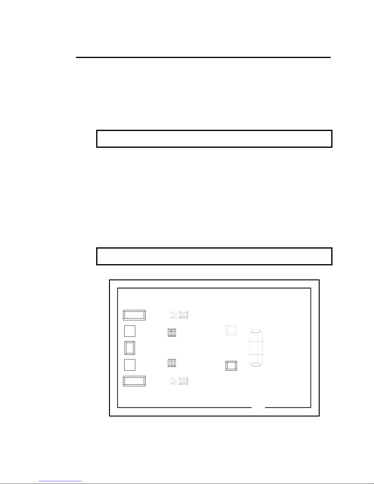
Once the room placement plan has been established, bring the crated
system into the listening room and place them according to the following
guidelines (see Figure 2.1):
• Sub Speaker crates at the back wall, behind the final speaker position.
• Sub Amplifier crate at the back wall, inboard of the sub speaker
crates.
• Top Speaker crates near the listening position.
• Crossover crate at the back wall between amplifier crates.
IMPORTANT: Place the crates of one channel with matching serial numbers on
one side of the room, opposite the crates of other channel.
Final Speaker
Speaker
Sub
Amp
Container
X-over
Crate
Sub
Amp
Container
Speaker
Sub
Crate
Sub
Crate
Position
Final
Sub Amplifiers
Positioning
Final Speaker
Position
Top
Speaker
Crate
Top
Speaker
Crate
Listening
Position
Figure 2.1 - Room set-up for unpacking.
11
Page 12
2.3 Opening the Crates
All of the crates features a one-piece top assembly which is fastened to the
crate bottom with screws around the lower perimeter.
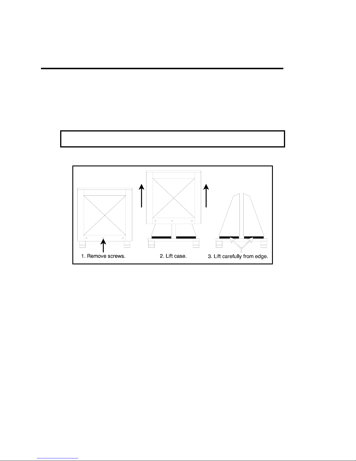
To unpack the crossovers, remove the screws and lift the upper portion of the
crate straight up (this will require two people). Carefully lift the cabinets by
the small overhang at the base. See Figure 2.2.
CAUTION: Three people are required for unpacking. To avoid injury, do NOT
attempt to unpack by oneself.
Figure 2.2 – To unpack the crossover cabinets..
12
Page 13
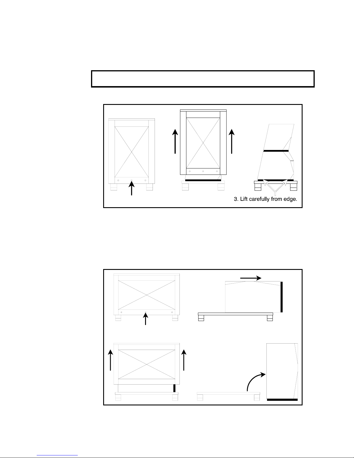
To unpack the upper speaker cabinets, remove the screws and lift the upper
portion of the crate straight up (this will require two people). Carefully lift the
cabinets by the small overhang at the base. See Figure 2.3.
CAUTION: Three people are required for unpacking. To avoid injury, do NOT
attempt to unpack by oneself.
1. Remove screws.
Figure 2.3 – To unpack the upper speaker cabinets..
2. Lift case.
To unpack the lower speaker cabinets, first remove the top of the crate. Then
slide the speaker part way off of the crate base so that the plastic bag can
be unfastened from the enclosure bottom. Stand the speaker up and the
bag can be slid off the top. Please refer to Figure 2.4.
3. Slide speaker,
1. Remove screws.
2. Lift case.
then undo bag.
4. Stand speaker up,
then remove bag.
13
Page 14

2.3 Opening the Sub Amplifier Crates
The Subwoofer Amplifiers are also packed in heavy-duty crates. To unpack,
remove the screws and lift the upper portion of the crate straight up (this will
require two people). Carefully lift the amplifiers off of the crate base. Take
them out of the plastic bag and check to ensure the following has also been
included:
• One (1) detachable AC linecord per amplifier
14
Page 15
3 System Set-up
WARNING: Failure to follow the set-up and wiring instructions explicitly may
cause damage to your loudspeakers and void your warranty.
Preparation
In order to begin system set-up, it is important that all materials are unpacked
and all cabinets are removed from the crates in accordance with Chapter 2,
Unpacking Instructions, beginning on page 9. Then remove all the empty
crates from the listening room to provide for additional assembly space.
Removing Apex Couplers from Set-up Blocks
Figure 2.4 – To unpack the lower speaker cabinets..
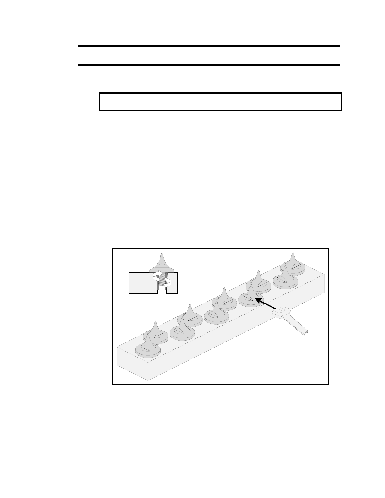
Remove all twenty Apex couplers from the two set-up blocks (see Figure
3.1). Three couplers will get installed in each of the six cabinets. Use the 1/2"
open end wrench on the wrenching flats to loosen as required.
Figure 3.1 – Removal of Apex Couplers.
15
Page 16

Left / Right Channel Matching
The two system channels (left and right) are consecutively serialized at the
factory. The elements of each channel are matched as a set for both their
electrical and aesthetic characteristics. Therefore, it is important to keep the
three cabinets of one channel (upper speaker, lower speaker, crossover)
which are labeled with the same serial number together on one side of the
room, separate from the three cabinets of the other channel.
IMPORTANT: Set-up the three cabinets of one channel with matching serial
numbers together on one side of the room, opposite the three cabinets of other
channel.
The serial number on the crossover cabinet is printed on the nameplate on
the bottom of the cabinet. The lower speaker cabinet has a serial number
label located on the top, near the back of the cabinet, and the upper
speaker cabinet has a serial number label located on the bottom, near the
back of the cabinet.
16
Page 17

3.1 Lower Speaker Cabinet Set-up
CAUTION: Three people are required for the set-up procedure. To avoid injury,
do NOT attempt to set-up by oneself.
1. Carefully lift and place each lower speaker cabinet in its measured final
location, as it becomes more difficult to move once the Apex couplers are
attached. Carefully route the sub's integral wiring between the legs of the
cabinet base, thereby protecting the wiring harnesses from becoming
pinched.
WARNING: The wiring harnesses are fragile and can be easily damaged by
pinching them beneath the cabinet base.
2. Lay the speaker on its side, using a blanket or other soft material to avoid
scratching the finish.
3. Install three Apex couplers on the bottom of the cabinet by fastening the
threaded ends of the couplers into the cabinet inserts (see Figure 3.2). Lightly
tighten the couplers and insure that the base of the coupler contacts the
bottom of the recess.
Coupler seated
on bottom of
recess
Figure 3.2 – Installation of Apex couplers.
4. Stand up the cabinet, again carefully routing the wiring harness to prevent
it from becoming pinched.
5. Measure and adjust the location of the cabinet within the listening room.
The cabinet should be set in place with a minimum of toe-in (no more than
two or three degrees).
17
Page 18
3.2 Upper Speaker Cabinet Set-up
CAUTION: Three people are required for the set-up procedure. To avoid injury,
do NOT attempt to set-up by oneself.
1. Lay the upper speaker on one side, using a blanket or other soft material
to avoid scratching the finish.
2. Install three Apex couplers on the bottom of the cabinet by fastening the
threaded ends of the couplers into the cabinet inserts (see Figure 3.2). Lightly
tighten the couplers and insure that the base of the coupler contacts the
bottom of the recess.
3. Stand up the cabinet. Carefully route the integral wiring between the legs
of the cabinet base, thereby protecting the wiring harness from becoming
pinched.
WARNING: The wiring harnesses are fragile and can be easily damaged by
pinching them beneath the cabinet base.
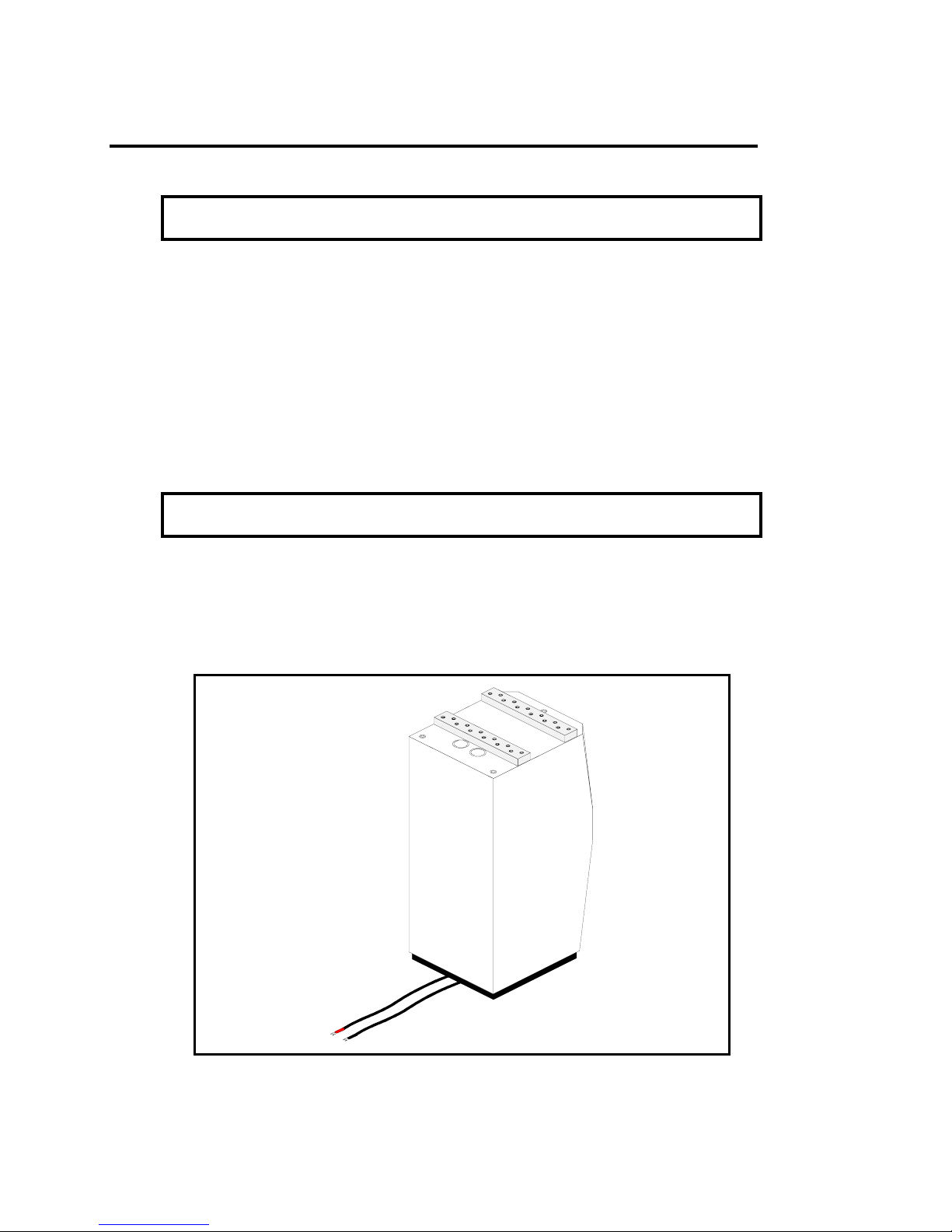
4. Place the two supplied set-up blocks on top of the lower speaker cabinet,
taking care NOT to cover the sockets or wiring guide tubes, as shown in Figure
3.3. The set-up blocks prevent scratching of the lower speaker cabinet
during positioning and alignment.
Figure 3.3 – Placement of set-up blocks atop lower speaker cabinet. Do
NOT cover the receiving sockets or wiring tubes with the set-up blocks.
18
Page 19
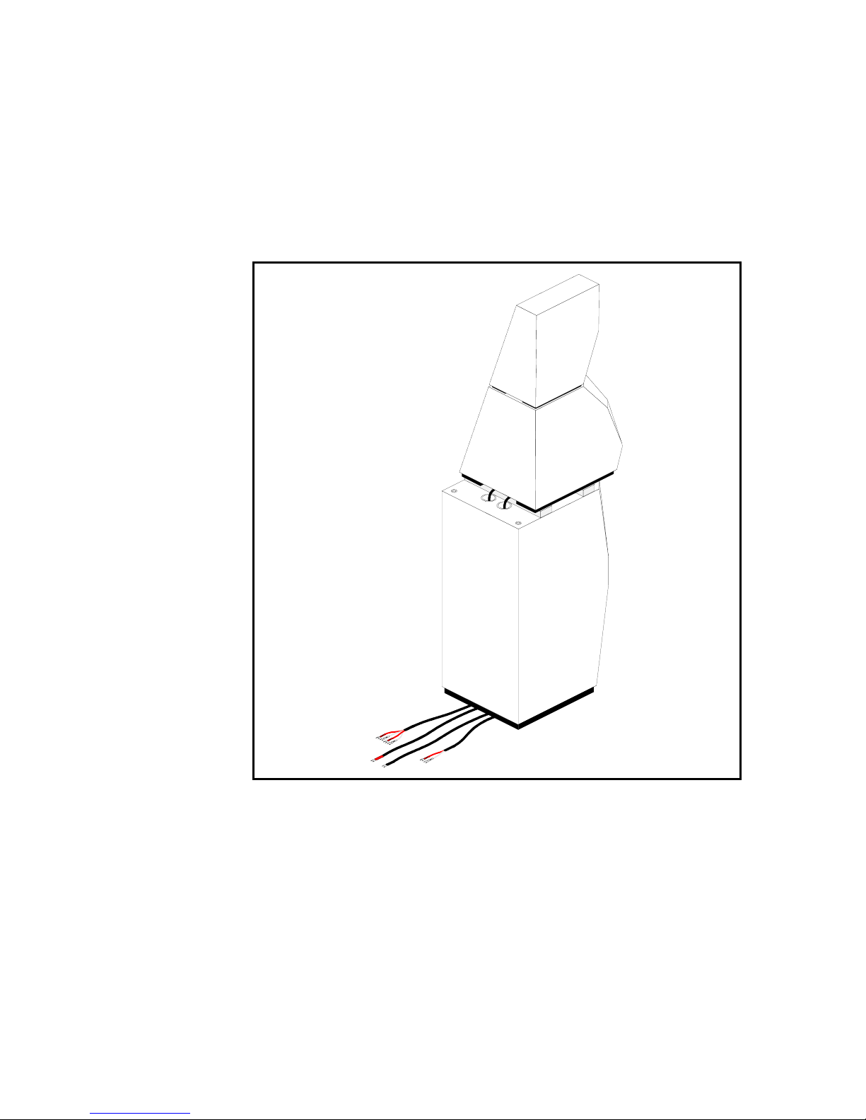
5. Carefully lift each upper speaker cabinet by the small overhang at the
base, and place it directly on top of the lower speaker cabinet, with the setup blocks between them. Then gently slide the upper cabinet slightly forward
to expose the wiring tubes in the lower cabinet (See Figure 3.4).
6. Route the upper speaker cabinet wiring through the wiring tubes and out
the bottom rear of the lower speaker cabinets, as shown in Figure 3.4.
Figure 3.4 – Placement of upper speaker cabinet atop lower speaker
cabinet. The upper speaker cabinet is slid forward to allow for routing of the
upper speaker cabinet wiring through the wiring tubes.
19
Page 20
6. Once the wiring is routed through the wiring tubes, slide the upper
r
speakers cabinets back, so that the couplers on the upper speaker cabinet
are directly above the sockets on the lower speaker cabinet (see Figure 3.5).
If necessary, gently adjust the upper speaker cabinet on the set-up blocks.
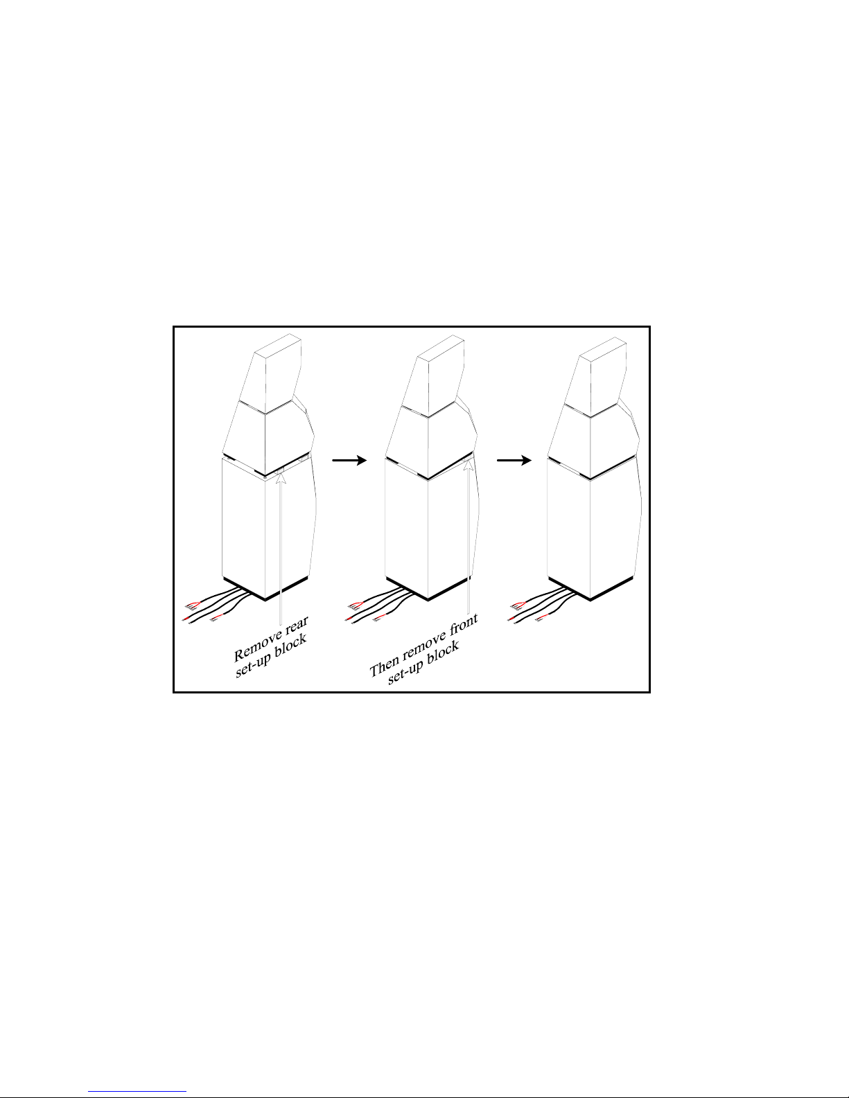
7. Remove the set-up blocks (refer to Figure 3.5): Lift the back side of the
upper speaker cabinet slightly, freeing the rear set-up block. Remove the
rear set-up block, and carefully lower the two rear Apex Couplers into their
respective receiving sockets. Then lift the front side of the upper speaker
cabinet slightly, remove the front set-up block, and lower the single front
Apex Coupler into its receiving socket.
Figure 3.5 – Removal of the set-up blocks between upper and lower speake
cabinets.
20
Page 21
3.3 Crossover Cabinet Set-up
CAUTION: Three people are required for the set-up procedure. To avoid injury,
do NOT attempt to set-up by oneself.
1. Lay the crossover cabinet on one side, just behind the speaker cabinet,
using a blanket or other soft material to avoid scratching the finish. The
cabinet should be oriented so that output terminals are adjacent to the back
surface of the speaker cabinets (see Figure 3.6).
OUTPUTS
INPUTS
Figure 3.6 – Proper placement of crossover cabinet behind speaker.
2. Install four Apex couplers on the bottom of the cabinet by fastening the
threaded ends of the couplers into the cabinet inserts (see Figure 3.2). Lightly
tighten the couplers and insure that the base of the coupler contacts the
bottom of the recess.
3. Do NOT stand up the crossover cabinet at this time, as you will need to
connect upper speaker harnesses to the output terminals in Section 4.
21
Page 22

3.4 The Felt Anti-Diffraction Mask
The anti-diffraction masks are installed at the factory, and fit within the
recesses on the cabinet face. It is very important that the felt mask make
physical contact with the face of the loudspeaker, as air space between the
felt and the speaker face will adversely affect sound quality.
Orientation of the upper Felt Mask
Should the felts come loose from the cabinets during shipping, remember to
reinsert them, as they are critical to loudspeaker performance. The upper felt
is beveled around the openings for the tweeter and midrange drivers. Be sure
to note the correct inside-outside orientation when installing it. The driver
openings are beveled on the side that faces the listener (away from the
speaker). Apply gentle pressure to the felt where it touches the velcro
mounting surface, while taking care not to damage the transducer
diaphragms.
WARNING: The transducer diaphragms are very fragile and are easily
damaged. Do NOT touch the diaphragms while positioning and installing felts.
22
Page 23

3.5 Sub Amplifier Set-up
Place the Sub Amplifiers in their final set-up positions, allowing 8 inches at the
rear for tightening the speaker output connectors.
The power transformer in the Sub Amplifier is located at the front-center of
the unit. Ideally, a few feet should separate this area from components which
potentially could pick up hum. These include preamplifiers, turntables, and
interconnect cables. In terms of providing adequate airspace for cooling, a
good rule of thumb is to allow 6 inches above and 3 inches on each side of
the unit.
23
Page 24

4 Wiring Instructions
WARNING: Failure to follow the set-up and wiring instructions explicitly may
cause damage to your loudspeakers and void your warranty.
Introduction
The Sentinel crossover is designed specifically for use with the drivers in the
upper speaker cabinet. The crossover is housed in a separate enclosure,
designed to be placed directly behind the speaker. Input to the upper
speaker cabinet drivers is facilitated by a two-position terminal block, using
your own speaker cable, and is for SINGLE-WIRING ONLY.
By contrast, the lower speaker cabinet is actively powered by, and directly
connected to the subwoofer amplifier. Wiring between the subwoofer
amplifier and subwoofer drivers is hard-wired to the subwoofer drivers.
The external crossovers must be used at all times for the upper speaker
cabinet drivers. The subwoofer amplifier powers the subwoofer drivers ONLY.
Do NOT connect the subwoofer amplifier (or your own amplifier) directly to the
upper speaker cabinet drivers.
Because of the weight and size of the Sentinel Active Reference System, it is
important to complete the set-up procedure before making wiring
connections (see Chapter 3, System Set-up, beginning on page 15).
Connections from the upper speaker cabinet to the crossover cabinet is
made by two wiring harnesses: a four-conductor wiring harness with labels
"HIGH" and "MID" for the tweeter and midrange, and a two-conductor wiring
harness with labels "LOW" for the woofer. These harnesses are hard-wired
directly to the upper loudspeaker cabinet drivers (routed through the wiring
tubes in the lower speaker cabinet), in order to provide the most
unobstructed signal path.
Connections from the subwoofer cabinet to the subwoofer amplifier are
made by a two-conductor wiring harness with labels "SUB". This harness is
hard-wired directly to the subwoofer cabinet drivers in order to provide the
most unobstructed signal path.
The Sentinel Active Reference System is equipped with nickel-plated brass
barrier terminals for connecting the harnesses and speaker cables. Ring
terminals or spade lugs designed for #10 screws are recommended for cable
termination.
Do NOT over-tighten the screws.
24
Page 25

4.1 Wiring and Field Interactions
The Sentinel Active Reference System is an extremely revealing, high-energy
device. Therefore, it is important to carefully plan the placement and routing
of wires when setting up your music reproduction system. Wiring is a task that
is often performed in a quick and haphazard manner, driven by the
excitement and anticipation of listening to one's brand new system.
Although it is compelling to rush into this process, don't rush!
Inductive field effects
The wiring in your music reproduction system is a very sensitive network of
electromagnetic conductors. Any changing magnetic fields that are in close
proximity to those conductors will induce small contaminating signals, thereby
degrading the music fidelity. In addition, the magnetic fields generated by
signals passing through one conductor will induce similar contaminating
signals in any adjacent conductors. These cross-inductive effects in a poorly
laid-out conductor network substantially increase the system noise floor,
resulting in a lack of image focus and resolution. In severe cases, oscillative
phenomena may also have disastrous effects on wide bandwidth amplifiers.
The following guidelines will minimize inductive field effects in your system:
• Physically separate the conductors whenever possible, as crossinductive effects decrease with the square of the distance between
elements. This applies to speaker cable, interconnects, digital cables,
and any AC cables in your system.
• When crossing of wires is unavoidable, cross them at right angles to
one another, and place non-conductive spacers between them.
• Avoid placing magnetic field devices near the conductors. Devices
such as halogen lights, fluorescent lights, dimmer switches, terminator
boxes, or computer equipment should not be placed in the vicinity of
the wiring or crossovers.
25
Page 26

4.2 Connecting Upper Speaker Cabinet to Crossover
1. Locate the upper speaker cabinet wiring harnesses: a four-conductor
wiring harness with labels "HIGH" and "MID" for the tweeter and midrange,
and a two-conductor wiring harness with labels "LOW" for the woofer. These
harnesses are hard-wired directly to the upper loudspeaker cabinet drivers
(routed through the wiring tubes in the lower speaker cabinet), in order to
provide the most unobstructed signal path.
2. Connect the upper speaker cabinet wiring harnesses (routed through the
wiring tubes in the lower speaker cabinet) to the OUTPUT terminal block on
the bottom of the crossover cabinet, as shown in Figure 4.1.
LOW
LOW
MID
MID
HIGH
HIGH
Figure 4.1 – Connecting the upper speaker cabinet wiring harnesses to the
crossover. RED is positive (+) and WHITE is negative (-).
Do NOT over-tighten the binding posts.
3. Check to insure the correct polarity: The spade with the RED label connects
to the positive (+) terminal, and the spade with the WHITE label connects to
the negative (-) terminal.
IMPORTANT: Correct polarity of connections is critical to performance. Check
to insure that the RED labeled spade is connected to the positive (+) post and
the WHITE labeled spade is connected to the negative (-) post.
4. Check to insure the correct driver connections: The spades with the "LOW"
label connect to the terminals labeled "LOW", spades with "MID" connect to
terminals with "MID", and spades with "HIGH" connect to terminals with "HIGH".
WARNING: Improper connection of drivers to crossover sections may
instantly destroy the drivers in question. Check all connections carefully
BEFORE power-up.
26
Page 27

4.3 Connecting Speaker Cable to the Crossover
1. Locate the input terminal block on the bottom of the crossover cabinets.
Route your own SINGLE-WIRED speaker cables to these INPUT terminals.
2. Connect your own speaker wires (for the upper speaker cabinet drivers) to
the INPUT terminal block on the bottom of the crossover cabinet, as shown in
Figure 4.2.
Figure 4.2 – Connecting your speaker cables to the crossover. Make sure to
check the polarity of the connections.
Do NOT over-tighten the binding posts.
IMPORTANT: Correct polarity of connections is critical to performance. Check
to insure that the polarity is correct at both the amplifier and crossover cabinet
terminals.
3. At this point you may stand up the crossover cabinet, leaving a minimum
of several inches between the crossover and speaker cabinets to avoid
possible collision and damage. Also take care to route the wiring between
the legs of the cabinet bases, thereby protecting the wiring harnesses from
becoming pinched.
WARNING: The wiring harnesses are fragile and can be easily damaged by
pinching them beneath the cabinet base.
27
Page 28

4.4 Connect Speaker Cable to your Amplifier
Although it is possible to power the Sentinel Active Reference System with a
single stereo amplifier, it is recommended to separate the amplification into
left and right channels. This is accomplished by using two mono amplifiers.
Separating the left and right channel amplification eliminates amplifier
inter-channel modulation due to the amplifier's finite output impedance and
aids in preserving the Sentinel's pristine phase relationships. Cross coupling
effects between the channels are minimized, thereby maintaining proper
stage width presentation. Isolating the power supply signals also allows better
noise rejection, resulting in improved focus, dynamics, and low-level detail.
When using two mono amplifiers, the Sentinel Active Reference System
external crossovers MUST be used.
For powering the upper speaker cabinet drivers, your amplifiers are driven
with a full-range signal from the pre-amplifier, and the frequency division is
performed by the passive crossover.
Use of active (electronic) crossovers for the Upper Speaker cabinet drivers will
result in inferior sound quality and may damage the drive units.
When using two mono amplifiers, it is important that they are identical units. It
is also important to be aware of the absolute polarity of the amplifiers. If the
amplifiers invert phase, be sure to compensate by reversing the polarity of the
speaker leads at the amplifier's output terminals.
28
Page 29

4.4 Connecting Subwoofer to the Sub Amplifier
1. Locate the lower speaker cabinet wiring harnesses: two single-conductor
wiring cables with the label "SUB". These harnesses are hard-wired directly to
the lower loudspeaker cabinet sub drivers, in order to provide the most
unobstructed signal path.
2. Connect the lower speaker cabinet wiring to the OUTPUT connectors on the
back of the sub amplifier.
3. Check to insure the correct polarity: The spade with the RED label connects
to the positive (+) terminal, and the spade with the WHITE label connects to
the negative (-) terminal.
IMPORTANT: Correct polarity of connections is critical to performance. Check
to insure that the RED labeled spade is connected to the positive (+) post and
the WHITE labeled spade is connected to the negative (-) post.
WARNING: Improper connection of drivers to crossover sections may
instantly destroy the drivers in question. Check all connections carefully
BEFORE power-up.
29
Page 30

4.5 Connecting Preamplifier to the Amplifiers
The Sentinel subwoofer section is actively powered by its own subwoofer
amplifier, whereas the upper speaker section is powered by your own
amplifier that is directly connected to the Sentinel crossover cabinet.
Therefore, you will need to make two separate output connections from your
preamplifier. This is accomplished in one of the following three methods:
1. Interconnect Y-cable at the preamplifier
A high-quality interconnect Y-cable may be the method with the least
amount of signal loss. Simply connect Y-cables directly at the preamplifier's
left and right channel outputs to divide the signals, resulting in two left
channel outputs and two right channel outputs. Then route one set of
divided outputs (right and left channel) to the subwoofer amplifier, and the
other set (right and left channel) to your own amplifier.
2. Two outputs at the preamplifier
Some preamplifiers are equipped with two sets of outputs. In this case, you
may simply connect one set of outputs (right and left channel) to the
subwoofer amplifier, and the other set of outputs (right and left channel) to
your own amplifier. If the preamplifier inverts the phase of one of the outputs,
be sure to compensate by reversing the polarity of the speaker leads at the
corresponding amplifier's output terminals.
IMPORTANT: Correct polarity of connections is critical to performance. Check
to insure that the polarity is correct at the amplifier and crossover cabinet
terminals.
3. Loop-Out from the Subwoofer Amplifier
The Sentinel Subwoofer amplifier is also equipped with loop-output
connectors that bypass the amplifier's circuitry. Utilizing this feature, you may
connect directly from these subwoofer amplifier loop-outputs to the inputs of
your own amplifier.
WARNING: Failure to follow the set-up and wiring instructions explicitly may
cause damage to your loudspeakers and void your warranty.
30
Page 31

5 Break-in Period
Your new Avalon Acoustics Sentinel Active Reference System has an initial
break-in period. It will not perform to its full sonic potential when first installed
in your system. This is due to a residual polarization of the dielectric materials
used in the crossover capacitors and internal wiring.
through the loudspeakers, the electrical signal will gradually anneal these
materials. Similarly, the suspensions of the drivers will reach their optimal
mechanical properties as the speakers are played. Only after the break-in
period will the full performance of your Avalon Acoustics loudspeakers be
realized.
The break-in process will occur naturally as music is played through the
system. To reduce the time required, it is recommended that the system be
played continuously, using either a digital source in the repeat mode or an
FM broadcast signal. The recommended break-in procedure is as follows:
• Initial warm-up: three to six hours of quiet music.
• Extended break-in: 200 to 300 hours of loud and dynamic source
material (e.g. Tangerine Dream, Optical Race, RCA 2042-2-P).
During the break-in period, the sonic properties of your loudspeakers may
undergo several gradual shifts as the various components break-in at
different rates. It is therefore suggested that the fine-tuning of the system be
delayed until after the break-in period is completed. However, during the final
phases of the break-in period, the sonic image will open up, the sound-stage
will gain specificity, the bass control and impact will increase, and the overall
sound will have a more relaxed, involving presentation.
1
As music is played
1
A high-voltage test is applied to wiring and capacitors during their manufacture.
This results in a residual polarization of the dielectric materials.
31
Page 32

6 Subwoofer Amplifier
Design Principle
The Sentinel subwoofer amplifier provides essential support for the lowest
octaves of the musical spectrum. As a fundamental component of the
Sentinel Reference System, the subwoofer amplifier has been specifically
designed to match the superlative speed and coherence of the Sentinel's
upper frequency response.
The 450 watt subwoofer amplifier is a push-pull with fully balanced circuitry.
The amplifier utilizes a (1 KVA) toroidal transformer with 8 high power Mosfet
devices. The amplifier has a built-in electronic crossover that is tuned
specifically to the subwoofer driver array and box alignment.
Room Compensation
Loudspeaker positioning within a room dramatically influences sound
reproduction quality. In particular, the distances to the room boundaries
define a complex system of wave nodes and antinodes that can play havoc
with low frequency response and phase characteristics. For example, the
reflection from each room boundary (floor, side walls, front and rear walls,
and ceiling) creates antinodes when the sound wavelength is about four
times the distance to that boundary. The overall effect of these reflections is
acoustic room loading, more commonly known as "room boom."
The Sentinel subwoofer amplifier has a sophisticated electronic network that
allows for in-room tuning and adjustment that can compensate for this
loading effect. We strongly recommend the application of room treatment
(See Section 7, Maximizing Performance) before attempting any
compensations using the subwoofer amplifier. Once your system and room
have been properly set-up and treated, the following procedure can assist
you in fine-tuning your system.
32
Page 33

Subwoofer Amplifier Control Panel
The back panel of the Subwoofer Amp enclosure has a variety of functions
activated by sequential use of the 7 buttons above the display. There is a
detailed Microsoft Powerpoint tutorial included with this manual. (See disc in
back of this manual.)
Your new Sentinel Sub Amplifier will allow you to work with any room size, and
can help address particular room frequency anomolies with a notch filter
designed to navigate around said frequencies. This room issues can only be
exactly identified by utilizing a proper room frequency sweep.
More refined empirical testing of room boundary effects and low frequency
tonal balance requires the use of impulse testing methods. Steady-state sinewave testing will reveal nothing
about the overall in-room performance of the
system or comparative compensation methodologies. We highly recommend
the Audio Quality Test from Acustica Applicata, at Italian telephone 0583730322, fax 0538-730914, email: Acustica@forum.lu.it
33
Page 34

7 Maximizing Performance
These details are imperative to obtaining optimum results from your Avalon
Acoustics loudspeakers.
Break-in
The break-in period is critical to maximizing sonic performance and should
take place before other adjustments (see the discussion on page 29). The
break-in should begin with three to six hours of quiet music, followed by 200 to
300 hours of loud and dynamic source material.
Separate Left / Right Amplifiers
It is recommended to separate the amplification into left and right channels,
by using two mono amplifiers. Separating the left and right channel
amplification minimizes cross coupling effects between the channels and
provides for better noise rejection, resulting in improved focus, dynamics, and
low-level detail. See page 28 (Connecting Speaker Cable to the Amplifier).
Felt Anti-diffraction Masks
The felt anti-diffraction masks are integral elements of the reference system
design. Unlike many other products, Avalon Acoustics loudspeakers are
designed to be used with the felts in place while listening, and removing them
will degrade the system's performance. It is very important that the felt
anti-diffraction masks make physical contact with the face of the
loudspeakers, as air space between the felt and the speaker face will
adversely affect sound quality. Since this is especially important near the
tweeter and midrange, applying gentle pressure to the felt near these drivers
is recommended. Take care not to damage the transducer diaphragms.
WARNING: The transducer diaphragms are very fragile and are easily
damaged. Do NOT touch the diaphragms while positioning and installing felts.
The upper felt is beveled around the openings for the tweeter and midrange
drivers. If the felts are removed, be sure to re-install them with the correct
inside-outside orientation: the driver openings are beveled on the side that
faces the listener (away from the speaker). Figure 3.7 on page 22 displays the
proper installation.
34
Page 35

Room Treatment and System / Listener Position
Selecting the proper room and listener positions within your listening
environment can dramatically improve system performance. The following
points highlight the fundamental concepts in room treatment and positioning
from the in-depth discussions in Chapter 9, Room Acoustics and Speaker
Position (beginning on page 41) and in Chapter 10, Listener Position (page
55):
• Left to right room symmetry aids in producing a balanced sound
stage.
• Image depth is enhanced when the distance to the rear wall is
increased. This is normally easier to accomplish when the speakers
are placed along the short wall of the listening room.
• The side wall and inter-speaker distances can be calculated using the
4 : 10 : 4 ratio.
• The most even bass response will be attained when the distances to
the side and rear walls are not overly similar.
• A comfortable, centered listening position at a minimum distance of
three meters from the system allows proper wave front convergence.
Toe-In
The exemplary horizontal polar response of the Sentinel Active Reference
System makes large amounts of toe-in unnecessary. The optimum toe-in
position is between two and three degrees. In situations where strong
reflections from the side walls are a problem, pointing the speakers inward up
to a maximum of five degrees can be helpful.
Apex Couplers
Supplied with your Avalon Acoustics loudspeakers are twenty Apex
couplers, used to couple the speaker and crossover cabinets to the floor,
thereby minimizing time-smearing resonance effects. The result is an increase
in focus and solidity of the sonic images.
On hardwood floors, use a large coin, such as a quarter, to protect the floor
from the pointed spike.
Refer to the set-up procedure in Chapter 3, System Set-up (beginning on
page 15) for details of Apex coupler installation.
35
Page 36

First Reflection Points
Since the ear/brain system tends to integrate the sounds arriving within a 10
millisecond time window, it is important to control the early reflections arriving
from the side walls to the listening position. A hard-surfaced wall can
produce a strong frequency-dependent reflection that can interfere with the
reproduced sound-stage, as well as change the perceived tonal balance of
the system. Therefore, damping these first reflection points is strongly
recommended. Please refer to Section 8.3, Early Reflections, beginning on
page 45, for further information.
Corner Treatment
It is important to control the corner and wall reflections of low frequency
sound. These reflections can cause significant distortions in phase and
amplitude, resulting in muddy bass definition, smeared bass transients, and
compressed image definition. Placing DAADS (available from Acustica
Appicata) at the room corners and centered at the walls behind the system
and listener can significantly control these bass colorations and restore the
quickness of bass transients.
36
Page 37

8 Care of Your Avalon Loudspeakers
Cabinet
Avalon Acoustics’ hardwood finished loudspeakers are supplied with a
special polish and two lint-free polishing cloths, in order to properly care for
the high quality furniture lacquer. The following polishing instructions should be
observed:
IMPORTANT: Use the supplied furniture polish ONLY. Do NOT use cleaners
that contain ammonia, strong solvents, or abrasive materials. Use of these
materials can degrade, scratch, or even DESTROY the finish.
1. Apply the supplied polish to one of the clean, lint-free polishing cloths (or
use cotton cloth that is clean and lint-free), and carefully wipe it on the
cabinet. Be careful NOT to apply the polish to the loudspeaker drivers.
WARNING: Do NOT apply polish to the loudspeaker drivers.
2. Wipe off the excess polish until the desired luster is achieved.
Crossover Cabinet
Your Sentinel crossover cabinets are manufactured with high-density solid
surface material. This beautiful finish also requires minimal attention. The
cabinets should be dusted with a soft, non-abrasive cloth, moistened with
water.
Felt Anti-diffraction Masks
The felt anti-diffraction masks may be removed from the cabinet and gently
vacuumed to remove dust. If the felt masks are removed, please note the
inside-outside orientation when re-installing the upper felts. The holes for the
tweeter and midrange are beveled on the side toward the listener, to
provide ideal dispersion characteristics.
Drivers
The drivers (sub-woofers, woofer, midrange, and tweeter) require no regular
maintenance. Do not attempt to clean the midrange or tweeter domes, as
they are easily damaged. If desired, you may remove dust from the subwoofer and woofer cones by using a small, soft dusting brush.
37
Page 38

9 Warranty
Your Avalon Acoustics loudspeakers are warranted against defects in
workmanship and materials for a period of three years, provided that the
enclosed registration card is returned to the factory within seven days of the
purchase date. If the registration card is not returned within the seven day
period, this warranty is null and void, and you will not be notified of future
updates. In the unlikely event that you did not receive the registration card
with your loudspeakers, please contact the factory immediately so that we
may send you a replacement card. This warranty is non-transferable to
subsequent purchasers within the original three year period. A complete
statement of warranty is given below. Please take the time to fill out and
return the enclosed warranty registration card.
In the Event of a Problem
In the unlikely event of a problem with your Avalon Acoustics loudspeakers,
the component most susceptible to failure is one of the driver units. If driver
replacement is required, have your dealer contact Avalon Acoustics. The
performance curves of the drivers in each pair of loudspeakers are kept on
file at the factory. This enables Avalon Acoustics to supply an exact
replacement unit, ensuring continued operation at the highest level of
performance. The defective driver must then be returned to the factory for
inspection to determine the status of the warranty claim. This on-site
replacement of the driver units eliminates the time and expense of shipping
the entire speaker to the factory for repair. All warranty claims must be made
through an authorized Avalon Acoustics dealer or distributor.
38
Page 39

Warranty Statement
1. Avalon Acoustics warrants the materials, workmanship, and proper
functioning of this product for a period of three years, provided that the
completed registration card is returned to Avalon Acoustics within seven days
of the date of purchase. If the registration card is not returned to the factory
within the seven day period, this warranty is null and void. If any defects are
found in the materials or workmanship of this Avalon Acoustics product, or if
the product ceases to properly function within the appropriate warranty
period from the date of first purchase, the unit will be repaired or replaced by
Avalon Acoustics or its authorized agent after receiving authorization from
the factory or dealer.
2. Purchaser must return the product, packaged in the original shipping
carton, freight prepaid to:
Avalon Acoustics
2800 Wilderness Place
Boulder, Colorado 80301
(303) 440-0422
3. Avalon Acoustics reserves the right to inspect any products which are the
subject of any warranty claim prior to repairing or replacing. Final
determination of warranty coverage lies solely with Avalon Acoustics. Any
products which conform to this warranty shall be repaired or replaced by
Avalon Acoustics as soon as possible following receipt of the product and
claim, but in no event later than 30 days after receipt of the product.
Out-of-warranty claims will be billed for labor, materials, return freight, and
insurance as required. Any product for which a warranty claim is accepted
will be returned to the purchaser and cost of shipping and insurance will be
factory prepaid within the boundaries of the USA. Units to be shipped outside
of the USA will be shipped freight collect only. This warranty gives specific
legal rights. The purchaser also has implied warranty rights, and may also
have other rights which vary from state to state.
4. This warranty is extended to the purchaser and any purchaser from him for
value.
5. Avalon Acoustics strives to manufacture the very finest possible equipment,
and therefore reserves the right to make changes in design and
improvements upon its products, without necessarily assuming an obligation
to retrofit such changes upon its previously manufactured models.
39
Page 40

6. The above warranty is the sole warranty given by Avalon Acoustics, and is
in lieu of all other warranties. All implied warranties, including warranties of
merchantability or fitness for any particular purpose shall be strictly limited in
duration to five years from the date of original purchase, and upon the
expiration of the warranty period (three years), Avalon Acoustics shall have
no further obligation of any kind whether express or implied, including but not
limited to merchantability. Further, Avalon Acoustics shall in no event be
obligated for any incidental or consequential damages as a result of any
defect or any warranty claim, whether express or implied. Some states do not
allow exclusion or limitation of incidental or consequential damages or
limitations on how long implied warranties last, so the above limitations and
exclusions may not apply to you.
7. Avalon Acoustics does not authorize any third party, including any dealer
or sales representative to assume any liability for Avalon Acoustics, or make
any warranty for Avalon Acoustics. The unit must not have been altered or
improperly serviced or repaired. The serial number on the unit must not have
been altered or removed.
8. Warranty registration cards must be completed and mailed to Avalon
Acoustics within seven days of date of purchase; otherwise, this warranty is
null and void. Avalon Acoustics may, at its option, require from the purchaser
valid proof of purchase (dated copy or photocopy of dealer's original
invoice).
9. If this product is used in a commercial or industrial application, then special
warranty exclusions may apply. Contact your dealer or Avalon Acoustics for
commercial warranty policies.
40
Page 41

10 Room Acoustics / Speaker Position
Introduction
The listening room forms the final link of the playback system, as important as
any other component in the chain. Just as an otherwise superb system is
handicapped by an inferior pre-amplifier (for example), so can a
well-matched system be hindered by poor room acoustics. It is not necessary
to listen to your system in a specially-designed sound chamber in order to
enjoy it. In fact, a dedicated listening room usually requires additional sound
treatment, only due to a lack of other items in the room that can help
provide good acoustics. However, a degree of attention to set-up can
greatly increase your listening satisfaction, no matter what your listening
situation.
Listening in a properly set-up room can be a startling experience. Perhaps it is
best described as if the front half of your listening space has been removed,
so that the recording site now occupies this part of your room. This can
ideally be an entirely three-dimensional space with dense, palpable
instruments that are spatially arrayed.
To optimize your equipment set-up and the listening-room acoustics requires
a basic understanding of the principles which affect the propagation of
sound in the room. Also, we will discuss the way in which our brain interprets
spatial cues, and how the room acoustics can affect our sonic perceptions.
41
Page 42

An Optical Analogy
Let us use a visual analogy to aid our understanding of acoustics. Imagine
that you are in a room that is lit only by a candle in its center. There is
(approximately) a uniform amount of light cast in all directions. If a large
mirror is held closely to candle, one half of the room becomes darkened,
while the other half receives twice as much light. This is because there are
effectively two candles now illuminating that half of the room, the real
candle, and the virtual (or reflected) candle. The energy that had been sent
to both sides of the room has now been concentrated in one side only.
If we repeat the same experiment using a large piece of black cloth instead
of a mirror, the results will be somewhat different. The side of the room behind
the cloth is darkened, just as before, but the level of light on the side of the
candle remains unchanged. This is because the light is absorbed by the cloth,
rather than being reflected back into the room.
Thus we can see that the energy can either be absorbed or reflected. A
similar situation occurs with sound waves, although we must account for the
much greater wavelengths of audible frequencies. Of course no material is a
perfect absorber or an absolute reflector. Furthermore, the sonic absorption
coefficient of a given material usually varies with frequency.
Basic Room Acoustics
The great majority of all listening rooms are rectangular, with parallel surfaces.
The walls and ceiling are typically hard surfaces, which are acoustically
reflective. These large areas are the predominating factors in the overall
room acoustics, although the other items in the room (furnishings, carpeting,
wall hangings, doorways, etc.) will also play a role. Without going into
excessive detail, there are four primary areas of potential concern:
• 1. Standing waves.
• 2. Flutter echo.
• 3. Early reflections.
• 4. Bass reinforcement.
The first three items are problems which should be reduced or eliminated. The
last item, bass reinforcement, needs to be matched to the entire system for
proper tonal balance.
42
Page 43

10.1 Standing Waves
The parallel surfaces of most listening rooms can lead to a potential problem
at any frequency. A sound wave can be repeatedly reflected from opposing
surfaces, back and forth. If the distance between the surfaces is an integral
multiple of one-half the sound wavelength, a standing wave will be set up.
This means that the incident and reflected waves combine with each other
so that a stationary pattern of high and low sound pressures is established in
the room. This irregular distribution of sound level is caused by cancellation
and reinforcement between the reflected and direct sound waves.
At high frequencies, this pattern of high and low sound pressure levels within
the room becomes too finely spaced to be discerned. However, when the
dimensions of the room are comparable to the wavelengths of the musical
notes, there will be obvious changes in the intensity of certain bass notes in
different locations within the room. Additionally, the existence of the standing
wave implies a resonant condition where acoustic energy is stored in the
room. This energy storage can result in "heavy", "muddy", or "slow" bass.
Since the presence of standing waves is caused by parallel reflective
surfaces, practically every listening room suffers from this problem to some
degree. However, several factors are working in our favor here. First, as the
room size increases, the affected frequencies become lower and thereby less
audibly apparent. Second, the presence of shelving or furniture against the
walls will break up the large surfaces, reducing the magnitude of the
problem. Third, upholstered furniture can absorb a significant amount of bass,
diminishing the build-up of resonant energy. Fourth, typical wall construction is
not completely reflective at low frequencies.
However, in some cases audibly objectionable standing waves will still be
present in the listening room. This can be noted by large variations of the
intensity of certain bass notes in different areas of the room. Another indicator
is an unevenness of loudness of different bass notes. (This is sometimes what is
actually on the recording, so be sure that this is consistently a problem on a
variety of recordings, or use a variable warble-tone generator.)
If you wish to reduce or eliminate standing waves that may exist in your room,
it will be necessary to reduce the low-frequency reflectiveness of at least one
of the parallel surfaces of opposing surfaces. The most effective method is to
use DAADS, available from Acustica Applicata. This is the only commercially
available sound treatment that absorbs significant amounts of energy below
400 Hz. Experimentation will be needed to determine the optimal locations.
43
Page 44

10.2 Flutter Echo
These parallel, reflective surfaces can also produce a different audible
problem. If there is little absorption at higher frequencies, a musical transient
containing high frequencies, such as a hand clap or the strike of a percussion
instrument, can be heard bouncing repeatedly between the surfaces. Called
flutter echo (or slap echo), these multiple reflections can obscure musical
detail. The situation is analogous to standing between two parallel mirrors,
when the outline of your reflection becomes more difficult to discern, due to
the additional reflected images present.
Again, it is only necessary to reduce the reflectiveness of one of the surfaces
in each pair of surfaces to eliminate flutter echo. However, we are also
constantly concerned with retaining left/right symmetry in order to maximize
imaging quality. Since we are concerned with the high frequencies, any soft
material is appropriate. Drapery or fabric wall hangings are quite effective on
the walls. Bookshelves also work well by breaking up the flat surfaces.
Carpeting should eliminate most potential problems between the floor and
ceiling.
44
Page 45

10.3 Early Reflections
Another situation that can reduce the subjective quality of reproduced
sound is the presence of early reflections. By early reflections, we are referring
to reflected sound waves that reach the listener within 10 to 20 milliseconds of
the direct signal from the loudspeaker.
When a reflected sound reaches the listener more than 40 milliseconds later
than the direct sound, the reflection is heard as a discrete echo. However, if
the reflected sound arrives within around 20 milliseconds of the direct sound,
the ear/brain system integrates the two sounds so that only one sound is
heard. This integration is done in such a way that spatial information is
preserved, providing an acoustical "picture" of the physical space that
created the reflections.
However, the source recording also contains ambient information that
portrays the original recording site. Early reflections in the listening room will
tend to obscure the ambient information in the recording, leading to a loss of
dimensionality or spaciousness. Secondary arrivals within the first 10
milliseconds are especially problematic, becoming less troublesome as the
arrival time lengthens to 20 milliseconds or so.
45
Page 46

Avoiding Early Reflections
The speed of sound is approximately one foot (30 cm) per millisecond.
Therefore, to preserve the natural sound stage on your recordings, there
should be no reflected sounds arriving at the listening position with a path
length less than ten feet (3 meters) longer than the direct path from speaker
to listener (see Figure 9.1). This means that if the speaker or listener is placed
closer than about 5 feet to a wall or other surface, that surface should be
covered with evenly absorbent material.
Direct Sound
Reflected Sound
Figure 9.1 - The reflected sound must travel further than the direct sound,
and therefore reaches the listener at a later time.
Since the floor is within 5 feet of the speaker, it is best to have a carpeted
floor to absorb floor reflections. A thick, dense carpet and pad will absorb
lower frequencies more effectively than a thin one. Due to their complex
structure, carpets and pads of natural materials, such as wool and jute,
exhibit a more uniform absorption over the frequency spectrum than do
synthetic materials.
46
Page 47

It is not necessary to acoustically treat the entire room to achieve good
results. Strategic treatment of specific locations can realize considerable
benefits. Remember that when sound waves reflect from a flat surface, the
angle of reflection is equal to the angle of incidence, just as a mirror reflects
light waves. Therefore, the most important location for sound absorbing
material is the point where the sound waves reflect to the listener (see Figure
9.2).
Angle X Angle Y
Reflected Sound
Direct Sound
Figure 9.2 The sound is reflected at the same angle that it struck the
surface; i.e., Angle X = Angle Y. Since light waves obey this same rule, a
mirror can be used to find the point which can be acoustically damped to
avoid early reflections.
Early reflections will tend to diminish the sound stage in the direction of the
reflections, i.e. early reflections from the side walls tend to reduce
sound-stage width, while early reflections from the back wall will reduce
image depth. We have found that a strong sense of depth enhances the
feeling of involvement when listening, due to the three-dimensional solidity of
images. Therefore, it is more important to have a greater distance from the
speakers to the rear wall than to the sides walls. Typically, this is easier to
achieve if the speakers are placed along the short wall of the listening room.
47
Page 48

Low Frequency Reflections
The first significant reflection of low frequency sound waves comes from two
corners behind the loudspeakers. Another important reflection occurs on the
wall behind the speakers, midway between them. Similarly, low frequency
corner and wall reflections take place at the opposite wall, behind the
listener. These reflections can cause significant distortions in phase and
amplitude, resulting in muddy bass definition, smeared bass transients, and
compressed image definition.
Placing DAADS (available from Acustica Applicata) at selected locations
and orientations in the listening room can significantly control these bass
colorations and restore the quickness of bass transients and the depth of
sound stage. We recommend placing floor-to-ceiling columns of DAADS at all
four room corners, at the wall behind the speakers centered between them,
and centered at the wall behind the listener. For listening rooms with low
ceiling height, consider treating the wall-ceiling junctions with DAADS as well.
Radial orientation of DAADS is critical. The traps at the wall directly behind
the listener, at the wall centered behind the speakers, and at the two corners
behind the listener should be placed with their absorptive sides (the side with
the seam) facing into the room, parallel with the side walls. The traps at the
two corners behind the speakers can be tuned to the listening room, using
the following rough guidelines (see Figure 9.3):
• seam toward center of room, parallel with back wall: adds depth to
sound stage
• seam away from center of room, parallel with back wall: adds width
to sound stage
• seam pointing into corner: sounds livelier, best tonal balance
Seam facing
into corner
Seam facing
into room
Seam facing
into corner
Seam facing
into room
Seam facing
into room
Seam facing
into room
Figure 9.3 – Tube trap placement and orientation. In this example, the tube
traps are oriented for best overall tonal balance.
48
Page 49

10.4 Bass reinforcement
By bass reinforcement, we mean the effect of the room boundaries on the
propagation of sound. It is widely known that speaker placement relative to
the floor and walls can affect the relative amount of bass that the system
produces.
To make this interaction more clear, let us refer to the optical analogy of the
candle. Similar to the way that the mirror reflected the light of the candle, so
can the surfaces near the loudspeaker reflect the sound waves back into the
listening room. When the wavelength of the sound is large compared to the
distance to the boundary, the reflected wave is substantially in-phase with
the original wave. When this condition is met, the coupling coefficient
between the speaker diaphragm and the air increases, and the speaker
efficiency increases. This changes the actual frequency response of the
speaker, and is not attributable to standing waves or other room resonances.
49
Page 50

As frequency increases and wavelength becomes more similar to the
distance to the boundary, the phase difference between original and
reflected waves increases, and the air coupling effect is diminished. In
particular, when the wavelength equals about four times the distance to the
boundary, the reflected wave is antiphase to the original wave, resulting in a
cancellation (dip) in the output. At frequencies above this level, the effect
becomes less significant and creates similar but smaller variations in output.
Figures 9.4 and 9.5 illustrate these concepts.
6
3
0
dB
-3
-6
10
Figure 9.4 - Change in frequency response resulting from placement of
speaker 3.3 feet from a reflective surface (relative to an anechoic
environment).
20 50 100 200 500
Hz
6
3
0
dB
-3
-6
10
Figure 9.5 - Same conditions as above, except speaker is 6.6 feet from the
reflecting surface. Note how the cancellation and reinforcement occur at
lower frequencies.
20 50 100 200 500
Hz
50
Page 51

There are typically three reflective surfaces near each speaker: the floor, the
rear wall, and the side wall. Each of these surfaces produces its own
reflection, and hence its own cancellation and reinforcement. By properly
selecting the distances to each surface, we can provide a uniform and
extended bass response. Conversely, improper placement of the
loudspeakers can result in uneven frequency response, resulting in diminished
bass quality.
In order to take full advantage of bass reinforcement and to provide the
most uniform and extended bass response, it is recommended that the
loudspeaker be placed between four and seven feet from the side wall, and
between eight and eighteen feet from the back wall. The measurements are
made from the wall to the center of the 9" woofer cone. The exact distances
are not overly critical, although the two distances should not be within about
33% of each other.
A good rule of thumb in establishing the lateral position of the Sentinel Active
Reference System is to apply the ratio 4 : 10 : 4. In other words, the distance
to the side wall is 4/18 (or about 22.2%) of the room width, and the distance
from speaker to speaker is 10/18 (or about 55.5%) of room width.
51
Page 52

10.5 Summary of Recommendations
Now that we have looked at some of the common problems of listening
rooms, as well as their cures, let us summarize our findings and
recommendations.
Flutter Echo and Standing Waves
These situations are the result of the room having parallel, reflective surfaces.
The potential problems are independent of the audio system, and need to be
addressed at the source. This means that at least one surface in an opposing
pair of surfaces needs to be made less reflective and/or non-parallel.
• Low Frequency Absorption
If a problem exists with standing waves, it is the low frequencies that will need
to be addressed. Remember that the absorption spectrum of different
materials and objects is not uniform. That is, some items will absorb only high
frequencies, and some objects may only absorb the middle frequencies. At
low frequencies, about the only common item that can absorb a meaningful
amount of energy is heavily upholstered furniture. Another effective means of
absorption is the use of DAADS, from Acustica Applicata.
• High Frequency Absorption and Room Symmetry
Since flutter echo is a high-frequency effect, it becomes much easier to
manage potential problems in this area. Almost any item attached to the
walls will be less reflective at high frequencies than the bare walls themselves.
Draperies, wall hangings, paintings, bookshelves and other items will normally
be present in the room, and will usually eliminate any possible problems. If
flutter echo is still audible, a fabric wall hanging provides an effective and
attractive cure.
Additionally, it is desirable to maintain a degree of left/right symmetry in the
room to preserve a balanced acoustic "space." For example, if your listening
room has full length draperies along the right wall, and the left wall is bare,
slap echo will not be a problem. Nonetheless, the sound-stage may be
somewhat distorted, and it could be beneficial to place a fabric hanging or
tapestry on the wall opposite the draperies.
• Parallel Surfaces
Although it is not generally possible to make the walls non-parallel, the same
effect is achieved by breaking up the large, flat surfaces with furniture and
shelving.
52
Page 53

Early Reflections
When arranging the furnishings in your listening room, remember that
reflective objects should not be within a five foot radius of either the speaker
or listener to avoid early reflections. This suggests the possibility of a
dual-purpose room, with one end devoted to music reproduction, and the
other end for another use, such as a study or office. In this way, the area
behind the listener will contain items that will reduce problems with standing
waves and/or flutter echo, while the zone around the speakers remains
relatively free from reflective objects.
If you wish to achieve an even more spacious sound-stage, it may be useful
to place a sonically absorbent material on the side and rear walls near the
speakers. This can be particularly effective at the points where the sound
wave is directly reflected to the listening position (a mirror can be used to
determine these points, as illustrated in Fig. 9.2). As the distance to the wall
becomes smaller, the suppression of these reflections becomes more
important.
In order to enhance the sound stage depth (and hence the feeling of
musical involvement), it is important to have a greater distance from the
speakers to the rear wall than to the sides walls. This is generally easier to
achieve if the speakers are placed along the short wall of the listening room.
Speaker Placement
Although the Sentinel Active Reference System may be placed in a variety of
positions relative to the walls of the room, it is still wise to apply the basic
guidelines described in this chapter to achieve optimal results. Plan on
placing the speakers along the short wall of the listening room. Then apply
the 4 : 10 : 4 ratio to establish the side wall distance (see page 51). The rear
wall distance should be greater than and not overly similar to the side wall
distance.
The suggested minimum distances for the Sentinel are 4 feet from the side
wall, and 8 feet from the rear wall (all distances are measured to the center
of the 9" woofer cone). This will provide the proper degree of bass
reinforcement, as well as minimize early reflections. There is no suggested
upper limit for the distances to the walls. Even a distance of 10 feet to one
wall and 15 feet to the other wall will provide suitable bass reinforcement,
and problems due to early reflections will be non-existent. However,
regardless of the absolute numbers used, the most even bass response will be
attained when the distances to the side wall and the rear wall are different
by at least 33%.
The exemplary horizontal polar response of the Sentinel Active Reference
System makes large amounts of toe-in unnecessary. The optimum toe-in
position is between two and three degrees. In situations where strong
reflections from the side walls are a problem, pointing the speakers inward up
to a maximum of five degrees can be helpful.
53
Page 54

10.6 A Listening Room Example
f
In order to make these points more clear, an example of a room layout is
given in Figure 9.6, illustrating the principles we have given.
DRAPERIES
TAPESTRY
Figure 9.6 - Example listening room. The area around the speakers is free o
SOFA
Listening
Position
SHELVES
SHELVES
CHAIR
DESK
TABLE
TABLE
any object that would produce early reflections.. A tapestry is hung opposite
the draperies to absorb the reflection from the side-wall and to help maintain
left-right symmetry. The area behind the listening position contains items
which help break-up standing waves and flutter echoes. Heavily upholstered
sofas will help avoid low-frequency standing waves, while a carpet absorbs
early reflections from the floor. Tube traps are placed in the corners,
centered at the wall behind the speakers, and centered at the wall behind the
listener.
54
Page 55

11 Listening Position
Just as loudspeaker positioning and room treatment can address the issues of
standing waves, flutter echo, reflections, and bass reinforcement, careful
attention to listening position is crucial to achieving accurate sound stage
placement, tonal balance, harmonic structure, focus, and image size. In
order to fully benefit from the Sentinel Active Reference System's outstanding
resolving potential, one must consider the three dimensional location of the
listening position in relation to the system and room.
Path Length Symmetry
In the previous chapter, it is recommended to maintain left/right symmetry in
the listening room to preserve a balanced acoustic "space." Similarly, if the
listening position is severely off to one side, there will be a significant
difference in the path length of sound emanating from the loudspeakers. The
resulting time differential will disturb the overall left/right balance and cause a
phase shift in the information coming from one channel relative to the other
channel. Depending on the frequencies involved, some sounds will arrive at
the listener's ear to some degree out of phase and cause cancellations or
drop-outs in the frequency spectrum. Therefore, it is important to maintain a
listening position that is reasonably symmetric to the room and centered
between the loudspeakers.
Time Alignment
The front planes of the Sentinel Active Reference System have been carefully
sculpted to establish accurate driver time alignment. In Figure 10.1, notice
that the acoustic centers of the drivers are situated so that the wave front
converges precisely at the listener's ear. In order to achieve this
convergence, it is recommended to place the listener in a comfortable chair
or sofa with the listener's ear about 110 cm above the floor and a minimum of
two, and preferably three meters or more from the system.
55
Page 56

3 meter path length
110 cm
Figure 10.1 - Convergence of the wave front occurs with the listener ear
situated approximately 110cm (43 1/2") from the floor and a preferred
minimum of 3 meters (118 inches) from the system.
Summary
When the listener and system are situated properly within a carefully planned
and set-up listening environment, the Sentinel multi-way system can deliver
high-energy output with point-source accuracy. It is crucial to begin with a
relatively large room that is acoustically treated reasonably and to follow the
set-up guidelines detailed in Chapter 9, Room Acoustics and Speaker
Position. The listener should be seated in a comfortable chair or sofa that is
centered between the loudspeakers. At the preferred minimum distance of
three meters from the system (the edge of driver wave front convergence),
you can expect a natural stage presentation and realize the Reference
System's potential for outstanding clarity and focus. On certain multi-miked
recordings however, the high frequency information may appear slightly
elevated within the sound stage. At four meters, the energy fields begin to
blend more integrally and tonal balance becomes more correct. The image
focus and size as well as the overall harmonic structure is improved, and the
music integrates into a coherent whole.
56
Page 57

12 Accuracy of Bass Reproduction
Introduction
We have all had the experience of listening to speakers with poor bass
quality. Perhaps the bass was muddy, or ill-defined. Possibly the bass was
exaggerated or bloated. In any case, these type of distortions are distracting
and can keep us from enjoying the full measure of the performer's intent.
When it comes to the reproduction of low frequencies, Avalon Acoustics
pursues a different design goal than most other manufacturers. Specifically,
we believe that the complete absence of stored resonant energy is of
paramount sonic importance. First, we will discuss some of the technical
aspects of bass reproduction and perception, and then explain how this
relates to the listening experience.
57
Page 58

12.1 Sensitivity to Time-Related Information
It is widely known that the human ear/brain system is extremely sensitive to
time-related distortions. This can be understood when one realizes that
directional and spatial information is provided by inter-aural time (and phase)
differences. During the period of man's evolution, the ability to accurately
determine the direction and distance of sound sources conferred a decided
survival advantage, hence our present day aural sensitivity to time-related
information.
This sensitivity to time-related information can be observed when listening to
audiophiles discussing the quality of a system's bass reproduction. Many of
the terms refer to temporal properties. A system with poor transient bass
response is described as "boomy", "heavy", "sluggish", or "slow". When the
transient response is accurate, the bass is characterized as "tight", "clean",
"quick", or "fast".
"Fast Bass"
The term "fast bass" would seem to be an oxymoron on the surface. After all, it
is the "slowness" of a note that makes it a low frequency. Nonetheless, the
term provides an accurate description of our subjective impression. Many
people have erroneously ascribed "fast bass" to the use of a light diaphragm
or the use of a powerful energizing system.
diaphragm can be set into motion that imparts a speaker with "fast" bass.
Rather, it is how fast that motion can be stopped, how quickly the stored
energy can be dissipated, that results in the sensation of "fast" bass.
1
In fact, it is not how fast the
1
The acceleration of an object is equal to the force exerted upon it, divided by
the mass of the object. Since a loudspeaker is used above its fundamental
resonance, it operates in what is known as the mass-controlled region. In this
region, high acceleration (large driving force and/or small driven mass) does not
imply extended high frequency response or fast transient response. Instead, high
acceleration confers high efficiency.
58
Page 59

12.2 Measurements of Audio Equipment
It should be recognized that measurements are not the final arbiter of sound
quality of audio components. Often times a measurement standard has
evolved because it is easily performed, or because it is easily repeatable, or it
has shown some link to certain audible characteristics. Unquestionably, it is
the latter criterion which is the most important one. After all, the listener is not
concerned with how a piece of audio equipment measures, he is only
concerned with the faithful recreation of the original musical event.
On the other hand, measurement techniques that correspond to audible
effects are an invaluable tool to the designer. However, it is the degree of
correlation with the subjective experience which is important, and anechoic
bass response does not have a high correlation with musical accuracy in the
listening room. In-room frequency response and transient accuracy are both
significant factors in determining subjective quality. Nevertheless, anechoic
frequency response is by far the most prevalent measurement used to
characterize speakers.
A Correlation with Amplifier Measurements
A striking parallel exists in the measurement of audio amplifiers. The power
output and distortion of an amplifier is invariably measured into an eight-ohm
resistor. It is widely acknowledged that this standard is far removed from the
actual conditions in which the amplifier will be used. One doesn't listen to
resistors, one listens to loudspeakers, and the load that the speaker presents
to the amplifier is nearly always highly reactive (varies with frequency). The
eight-ohm resistive load has developed as a standard because it somewhat
approximates a speaker load, is easily reproducible by different testing
facilities, and it represents something of a lowest common denominator. That
is, while everybody recognizes that a different load should be used for
amplifier testing, nobody can agree as to what that alternative should be.
In the last decade, there has been a growing awareness of the importance
of an amplifier's capability to drive a real-world loudspeaker. This is the reason
we have seen the emergence of amplifiers with high current output
capabilities, and a lack of current-limiting or similar protection circuitry. The
ability to drive reactive loads has been accepted as having a higher
correlation with audible qualities than the traditional measurement into a
load resistor.
2
2
The cynic will also note that a resistive test load produces the most impressive
measurements for use in advertisements.
59
Page 60

Loudspeaker Measurements
Returning to loudspeakers, a similar situation has developed. Although
nobody listens to music in an anechoic chamber, loudspeaker measurements
are commonly performed in them.
3
Although various proposals have been
made for performing low frequency measurements in a more realistic setting,
there has been no agreement as to what that setting should be.
Loudspeakers continue to be measured in a test chamber that is equivalent
to the absence of any room at all.
There is a developing appreciation that this traditionally performed
measurement is not an accurate predictor of the performance actually
attained in the listener's room. Certainly, in-room frequency response is more
important than anechoic response in determining a speaker's tonal
accuracy. Placement of the speaker within a room will cause changes in the
frequency response compared to the anechoic condition.
4
At lower
frequencies, the speaker's output is modified by the acoustic loading
presented by the walls and floor. However, when making measurements, it is
difficult to separate the effects of a room's bass reinforcement from standing
waves and other resonances associated with that room.
3
Since an anechoic chamber which performs accurately to low frequencies is
extremely large and expensive, other measurement methods are also commonly
used. These include near-field measurements, when the microphone is extremely
close to the driver, and half-space measurements, when the speaker under test is
buried with its front baffle flush with the ground, facing upwards. Both of these
methods are equivalent to anechoic measurements below the frequency at
which the speaker baffle appreciably changes the acoustic load to the woofer,
typically between 100 and 200 Hz. Note that these conditions are also
non-representative of an actual listening situation.
4
Since this discussion is concerned with the reproduction of low frequencies, we
will not delve deeply into the high-frequency variations between the anechoic
response and the in-room response of a loudspeaker. Briefly, the interaction of
the dispersion pattern of the speaker with the reflective surfaces in the room (and
the variation of both with frequency) creates an in-room frequency response that
may vary markedly from the anechoic response.
60
Page 61

Designing for Accurate Bass Reproduction
How, then, does one arrive at the goal of a loudspeaker that provides tonal
accuracy in the listening room? The answer, in large part, comes in the form
of the digital computer. It is possible to create a mathematical model of a
listening room, and predict the response of a given speaker in that room. With
the computer model, it is quite easy to change the position of the speaker in
the room, or other parameters of the model. In this way, a composite picture
can be created of a wide variety of rooms and speaker locations. This
enables one to design the speaker so that it interfaces properly with the
listening environment and provides correct bass response in real-world
environments.
The accuracy of the computer model must also be tested in the physical
world, using pink noise, warble tones, and time-delay spectrometry for
verification. The final, and most important check, is the listening test. Theory
and measurements become useless if they do not agree with what our ears
tell us. Even the best measurement methods provide little more than a
simplified, one-dimensional translation of what is, in reality, an extremely
complex, multi-dimensional experience. Again, the goal is the recreation of a
musical event, and the faithfulness of that recreation can only be determined
through listening.
61
Page 62

12.3 Listening Qualities
Now we will turn our attention to the listening experience, and describe how
these measurable properties correlate with our subjective impressions.
There are two main factors which affect subjective low-frequency accuracy,
frequency response and transient response. At low frequencies, these two
descriptions are different aspects of the same event.
purposes of this discussion, we will treat these two topics separately as much
as is possible.
Frequency Response Effects
As you listen to music, images of the instruments that created the sounds are
elicited. For instance, one can tell the approximate size of a drum from the
sound it produces. On a high-resolution playback system, finer details can be
heard; i.e., is the head made of plastic or calfskin? Is the player using light
sticks or heavy ones?
A relatively broad-band emphasis (or de-emphasis) of a given frequency
range can tend to exaggerate (or diminish) the relative size of the instruments
playing in that range. A useful tool for evaluating these distortions of size is a
recording of a small group of unamplified acoustic instruments made with a
simple microphone set-up. One superb example is the series of acoustic jazz
recordings available from Chesky Records. These are made with a
single-point stereo microphone, and feature a photograph of the recording
session that shows the location of the players.
5
Nevertheless, for the
Listening for Size Distortions
Play a recording of this type, with the volume adjusted to achieve a natural
playback level. As you listen, create a mental image of the players based on
sounds being recreated. Then ask yourself, "Does this sonic image correspond
to the musical instruments that generated these sounds?"
Is the portrait a natural one, or are certain elements distorted? Does a
stand-up bass sound like the correct size, or is it exaggerated, sounding like it
is ten feet tall, or as if the strings are the size of ropes? A speaker with
excessive in-room bass response can create these effects. On the other
hand, a speaker system with rolled-off bass can shrink the size of instruments,
turning the same stand-up bass into a cello-sized instrument.
5
Below about 200 Hz, virtually every woofer operates as a minimum-phase device.
This means that the responses in the time-domain and the frequency-domain are
inextricably linked, and that the one generates the other. Thus, two woofers with
the same frequency response will necessarily exhibit the same time (phase)
response. However, many crossover networks display non-minimum phase
response, and will thereby alter the phase response of the woofer in the speaker
system.
62
Page 63

Transient Response Effects
A speaker with poor transient response will store energy, releasing it after the
initial musical transient has passed. This causes a loss of detail and obscures
important musical information. Also associated with poor transient response is
a narrow-band resonance, which can emphasize specific notes.
When listening for the low-frequency transient accuracy of a speaker, it will
be useful to utilize a broad variety of recordings. Try playing a rock or jazz
group, and listen to the interplay between the drummer and the bassist. Is it
easy to distinguish the kick drum from the bass, or is there a blurring of
low-frequency detail caused by the speaker's time-smear?
To listen for narrow-band low frequency resonances, use a recording with the
bass line played by a synthesizer. As you listen to the bass line, are the
individual notes of equal level, or are some of them more prominent than
others? Electronic instruments can be more useful for this test since acoustic
instruments have resonances of their own which can hide flaws in the
speaker, unless you are intimately familiar with the instrument and the
recording. Similarly, an electric bass that has been recorded by miking its
speaker/amplifier will exhibit the resonances of its speakers, which are
inevitably considerable, masking defects in the loudspeaker under
evaluation.
6
6
There is a technique known as "direct injection" where the signal from an electric
instrument is connected directly from the amplifier to the recording console,
bypassing the speakers. In this instance, an electric bass will prove to be a
consistent low-frequency source. The difference between direct injection and
miking of the speaker/amplifier is easily audible with high-quality speakers.
63
Page 64

12.4 Active Subwoofer System
Designing a loudspeaker system for accurate low-frequency reproduction is a
challenging proposition. Given a reasonable listening environment, there is
very good correlation between the anechoic and in-room responses at
frequencies above 350 Hz. However, at low frequencies, boundary effects
come into play, significantly altering the in-room response.
Anechoic Frequency Response vs. In-Room Frequency Response
It must be remembered that very little listening actually takes place in
anechoic chambers. Placement of the speakers in a real-world listening room
will boost the bass response of the speaker, as explained in Section 8, Room
Acoustics and Speaker Position, beginning on page 41.
Active Control of Bass Energy
In order to properly control the bass energy and achieve a flat frequency
response in-room, the Sentinel Active Reference system employs an active,
powered subwoofer system. The subwoofer amplifier is specifically designed
to handle the high-power demands of low-frequency signal, via the
amplifier's massive toroidal transformer, exceptional storage capacity, and
unmatched high voltage/current regulation.
The Sentinel Active Reference System's high-capacity subwoofer amplifier
handles the most demanding low-frequency passages and actively controls
and maintains transient speed and accuracy. Coupled with the dual-driver
ultra-lightweight diaphragm subwoofer section, Sentinel produces deep,
accurate bass down to 16 Hz, with complete freedom from stored resonant
energy.
64
Page 65

13 Features
• Application of new cabinet research features nineteen separate
aperiodically damped internal chambers in three distinct speaker
cabinets for superior resonance control.
• Advanced light weight driver diaphragm materials minimize energy
storage and time-domain distortion.
• High-definition diamond membrane tweeter. Midrange driver has
ultra-light concave ceramic dome diaphragm.
• Extremely stiff and light Nomex-Kelvar Woofer and Subwoofer cones
provide unmatched stiffness and high energy transient accuracy.
• Each driver individually tested and matched for optimum
performance.
• Moderate impedance characteristic allows for ideal interface with
any amplifier.
• Star-grounding techniques eliminate signal modulation.
• Crossover circuitry is hard-wired with surface-only conductors,
eliminating deleterious sonic effects of printed-circuit boards.
• Exceptionally low noise, highly reactive induction technology reduces
inter-driver jitter, resulting in state-of-the-art micro-dynamics.
• Direct harness wiring to drivers, with oversize barrier strips and screw
terminals at crossover connections for maximum signal transfer.
• Crossover elements meticulously oriented to minimize interaction of
magnetic fields.
• Polypropylene and coaxially wound polystyrene capacitors used
exclusively to minimize energy storage.
• Newly developed proprietary damping circuits control each driver's
electrical parameters, reducing interaction with the amplifier.
• Crossover circuitry housed in a rigid external enclosure, providing
maximum isolation from vibrations.
• Constrained-mode damping in golden section laminations absorb
cabinet vibrations.
• Six-inch thick front panel supplies acoustically inert wave-launch
platform.
• Acoustically-engineered beveled anti-diffraction felts minimize
reflective and diffractive effects.
• Distinctive faceted cabinet design provides optimal polar
characteristics.
65
Page 66

14 Specifications
Loudspeaker
Driver Complement 1" concave diamond dome tweeter
3 ½" concave ceramic dome midrange
9" Nomex-Kevlar composite cone woofer
Two 13" Nomex-Kevlar composite
cone subwoofers
Sensitivity 88 dB (2.83V, 1 meter)
Impedance 4 ohms nominal (3.6 ohms minimum)
Frequency Response 16Hz to 100kHz (+/- 1 dB, anechoic)
Recommended Amplifier Power 100 to 1000 watts
Wiring Methods Two position terminal block, designed to
accept spade lugs for #10 screws.
Dimensions Overall height: 69 inches (1.75 meter)
Overall width: 17 inches (0.43 meter)
Overall depth: 37 inches ( 0.94 meter)
Weight 910 pounds (415 kg) crated system
(not including sub amps)
Subwoofer Amplifier
Sensitivity: User Adjustable
Input Impedance: 20 K + 20K balanced ohms
Gain: Adjustable
S/N Ratio: 113 dB (unweighted)
THD+N: 0.002%
Rated Output: 500 Watts per channel into 4 ohms
Dimensions: 19" w x 19" d x 9" h (48cm x 48cm x 23cm)
Weight: 45 lbs each (55 kg each)
66
Page 67

15 Notes
Sub Amplifier settings for future reference.
Band Pass settings________________
Amplitude setting_________________
67
 Loading...