

Page 1
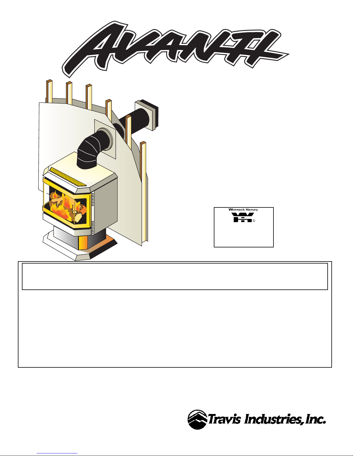
By Avalon
Direct Vent Heater
¥ HORIZONTAL or VERTICAL VENT
¥ MOBILE HOME APPROVED
¥ CLASS A CHIMNEY RETROFIT
Listed
(ANSI Z21.44)
WARNING: Improper installation, adjustment, alteration, service or maintenance can cause
injury or property damage. Refer to this manual. For assistance or additional
information consult a qualified installer, service agency, or the gas supplier.
- Do not store or use gasoline or other flammable vapors and liquids in the vicinity of this or
any other appliance.
- Installation must be performed by a qualified installer, service agency or the gas supplier
IF YOU SMELL GAS
¥ Do not try to light any appliance.
¥ Do not touch any electrical switch; do not use any phone in your building.
¥ Immediately call gas supplier from a neighbor's phone. Follow the gas supplier's instructions.
¥ If you cannot reach your gas supplier, call the fire department.
AVANTI DV
- September, 1995 -
Installer: After installation give this manual
to the homeowner and explain
operation of this heater.
10850 117th Place N.E. Kirkland, WA 98033
Page 2
PAGE 2 SAFETY PRECAUTIONS
¥ IF YOU SMELL GAS:
* Do not light any appliance
* Extinguish any open flame
* Do not touch any electrical switch or plug or unplug anything
* Open windows and vacate building
* Call gas supplier from neighbor's house, if not reached, call fire department
¥ This unit must be installed by a qualified installer to prevent the possibility of
an explosion. Your dealer will know the requirements in your area and can
inform you of those people considered qualified. The room stove should be
inspected before use and at least annually by a qualified service person. More
frequent cleaning may be required due to excessive lint from carpeting,
bedding material, etc.
¥ The instructions in this manual must be strictly adhered to. Do not use
makeshift methods or compromise in the installation. Improper installation
will void the warranty and safety listing.
¥ This stove is either approved for natural gas (NG) or for propane (LP).
CH
- or -
4
Burning the incorrect fuel will void the warranty and safety listing and may
cause an extreme safety hazard. Direct questions about the type of fuel used to
your dealer. Check the label and flame adjust knob on the gas control valve.
HC
Ok
Gas
83
ON
VENT
HI
OFF
T
P
O
L
PILOT ADJ
LO
I
RED
HI
LO
LP ( Pr opane)
THIS CONTROL
HAS BEEN
CONVERTED TO
LP
¥ Contact your local
building officials to
obtain a permit and
information on any
installation restrictions or
inspection requirements in
your area. Notify your
BLUE
-o r-
THIS CONTROL
HAS BEEN
HI
CONVERTED FOR
LO
NATURAL GAS
Na tu ral Ga s
¥ If the flame becomes
sooty, dark orange in
color, or extremely tall,
do not operate the stove.
Call your dealer and
arrange for proper
servicing.
insurance company of this
stove as well.
¥ It is imperative that
control compartments,
screens, or circulating air
passageways of the stove
be kept clean and free of
obstructions. These areas
provide the air necessary
?
¥ Do not operate the stove
if it is not operating
properly in any fashion or
if you are uncertain. Call
your dealer for a full
explanation of your stove
and what to expect.
for safe operation.
¥ Do not store or use
gasoline or other
flammable liquids in the
vicinity of this stove.
¥ Do not operate if any
portion of the stove was
submerged in water or if
any corrosion occurs.
¥ Keep all furniture or other
combustible items at least
36" away from the front
of the stove.
Page 3
SAFETY PRECAUTIONS (CONTINUED) PAGE 3
¥ Do not place clothing or
other flammable items on
or near the stove.
Because this stove can be
controlled by a thermostat
there is a possibility of the
stove turning on and
igniting any items placed
on or near it.
¥ The viewing glass should
be opened for service only
(see the maintenance
section of this manual).
¥ Any safety screen or
guard removed for
servicing must be
replaced prior to
operating the stove.
¥ Operate the stove
according to the
instructions included in
this manual.
¥ If the main burners do not
start correctly turn the gas
off at the gas control
valve and call your dealer
for service.
¥ Light the stove using the
built-in piezo igniter. Do
not use matches or any
other external device to
light your stove.
¥ Never remove, replace,
modify or substitute any
part of the stove unless
instructions are given in
this manual. All other
work must be done by a
trained technician. Don't
modify or replace orifices.
¥ Allow the stove to cool
before carrying out any
maintenance or cleaning.
¥ The pilot flame must
contact the thermopile,
thermocouple and deflect
off the pilot hood when
turned on. If it does not,
turn the gas control valve
to "OFF" and call your
dealer.
¥ This unit is not for use
with solid fuel
¥ Do not place anything
inside the firebox (except
the included fiber logs).
¥ If the fiber logs become
damaged, replace with
Travis Industries log set.
¥ Do not touch the hot
surfaces of the stove.
Educate all children of the
danger of a hightemperature stove. Young
children should be
supervised when they are
in the same room as the
stove.
¥ Instruct everyone in the
house how to shut gas off
to the appliance and at the
gas main shutoff valve.
The gas main shutoff
valve is usually next to
the gas meter or propane
tank and requires a
wrench to shut off.
This
Manual
¥ Do not throw this manual
away. This manual has
important operating and
maintenance instructions
that you will need at a
later time. Always follow
the instructions in this
manual.
¥ Plug the stove into a
115 V. grounded
electrical. Do not use an
adapter plug or remove
the grounding plug.
¥ Don't route the electrical
cord in front of or over
the stove
¥ Travis Industries, Inc.
grants no warranty,
implied or stated, for the
installation or
maintenance of your
stove, and assumes no
responsibility of any
consequential
damage(s).
Page 4
PAGE 4 TABLE OF CONTENTS
Introduction & Important Information
Introduction & Important Information ............. 1
Safety Precautions
Safety Precautions......................................... 2
Features & Specifications
Installation Options ........................................ 5
Features......................................................... 5
Heating Specifications ................................... 5
Dimensions.................................................... 5
Fuel................................................................ 5
Emissions....................................................... 5
Electrical Specifications ................................. 5
Installation
Installation Preparation.................................. 6
Items Required for Installation ....................... 6
Items Packed with the Avanti DV................... 6
Items Packed with the Stove Shell ................ 6
Items Packed with the Pedestal..................... 6
Order of Installation ....................................... 6
Door Removal ............................................... 6
Pedestal Attachment ..................................... 7
Stove Shell Assembly.................................... 7
Gas Inlet Installation ...................................... 10
Floor Protection Requirements...................... 11
Stove Placement Requirements .................... 11
Alcoves ................................................... 11
Minimum Clearances.............................. 11
Gas Line Installation ...................................... 12
Fuel......................................................... 12
Gas Line Connection.............................. 12
Gas Inlet Pressure.................................. 12
Manifold Pressure................................... 12
Vent Requirements........................................ 13
Approved Vent Configurations....................... 14
Restrictor Position................................... 14
Elbows.................................................... 15
How to Measure Vent Lengths ............... 15
Vertical Terminations with No Elbows .... 16
Vertical Term. with Two 45° Elbows ....... 16
Horizontal Termination (one 90° elbow) . 17
Vertical Term. with Two 90° Elbows ....... 18
Horizontal Vent Termination Requirements... 19
Vertical Vent Termination Requirements ....... 19
Electrical Connection ..................................... 19
Glass Removal .............................................. 20
Installation (Continued)
Installing the Logs and Coals........................ 21
Installing the Glass ........................................ 22
Leak, Pilot, and Flame Testing ..................... 22
Operating Your Stove
Before You Begin.......................................... 24
Location of Controls....................................... 24
Starting The Pilot Flame ............................... 25
Starting the Stove for the First Time .............. 26
Turning the Stove On and Off ....................... 26
Adjusting the Flame Height............................ 26
Adjusting the Blower Speed.......................... 27
Normal Operating Sounds ............................. 27
Maintaining Your Stove
Maintaining Your Stove's Appearance........... 28
Cleaning Your Stove ..................................... 28
Yearly Service Procedure .............................. 28
Troubleshooting
Troubleshooting Table .................................. 29
How this Stove Works.................................... 30
What Turns the Main Burners On & Off.. 30
What Prevents Gas Buildup................... 30
Why Nothing Should Be Placed
Against the Stove .................................. 31
Wiring Diagram ............................................. 31
Replacement Parts List.................................. 31
Warranty
Warranty ........................................................ 32
Listing Information
Safety Label................................................... 33
Optional Equipment
Propane (LP) Burner Pan ............................. 34
Remote Control.............................................. 35
Thermostat.................................................... 36
Gold Trim Kit .................................................. 36
Addendum
Altitude Considerations ................................. 37
Class A Chimney Conversion Kit................... 37
Index
Index .............................................................. 38
Symbols Used in this Manual
The illustration below details what the symbols used along the left margin indicate.
Requirement
¥¥
¥¥
11
11
++
++
Hint
NoteWarningStep
!!
!!
??
??
Page 5

FEATURES AND SPECIFICATIONS PAGE 5
Installation Options:
¥ Residential or Mobile Home
¥ Straight or Corner Placement
¥ Bedroom Approved
¥ Alcove Approved
¥ Vertical or Horizontal Vent
¥ Approved for use in homes of
unusually tight construction
Heating Specifications:
Approximate Heating Capacity (in square feet)* 600 - 1600 600 - 1600
High Burn Input Rate (In BTU's) 31,000 31,000
Low Burn Input Rate (In BTU's) 18,000 17,000
Efficiency** 81.5% 83.3%
AFUE (Annual Fuel Utilization Efficiency) 72.6% 74.2%
* Heating capacity will vary with the home's floor plan and insulation, natural gas or Propane BTU rating, and outside temperature.
** Efficiency rating is a product of thermal efficiency rating determined under continuous operation independent of installed system.
To measure the net BTU's, multiply the BTU input by the efficiency percentage (81.5% for natural gas, 83.3% for LP).
Dimensions
Features:
¥ Works During Power Outages (standing pilot)
¥ High Efficiency; 81.5% Natural Gas, 83.3% LP (Steady State)
¥ Optional Thermostat or Remote Control
¥ Realistic "Wood Fire" Look
¥ Convenient Operating Controls
¥ Variable-Rate Heat Output
¥ Quiet Blower for Effective Heat Distribution
¥ Low Maintenance
Natural Gas LP (Propane)
24-1/2"
2-3/4"
4-1/2"
20"
31-1/4"
Fuel: The stove is designed either for natural gas or for propane. Check
the sticker on the top of the gas control valve.
Emissions: This unit has passed the ANSI emission standards for vented room
stoves as tested by Warnock Hersey, LTD.
Electrical Specifications: 115 Volts, 1.3 Amps, 60 Hz (150 watts on high)
Page 6
PAGE 6 INSTALLATION
Installation Preparation
! This appliance must be installed in accordance with all local codes, if any; if not, follow ANSI
Z223.1 and the requirements listed in this manual. Failure to follow all of the requirements
may result in property damage, bodily injury, or even death.
! When installed in a mobile home, this appliance must be installed in accordance with the
Manufactured Home Construction and Safety Standard, Title 24 CFR, Part 3280, or if not
applicable, the Standard for Manufactured Home Installations (ANSI A225.1--1984).
! Notify your insurance company before hooking up this stove.
! The requirements listed below are divided into sections. All requirements must be met
simultaneously. The order of installation is not rigid Ð the qualified installer should follow the
procedure best suited for the installation.
Items Required for Installation
¥ Avanti Stove Shell
(Black #99200320, Almond #99200321, Green #99200322)
¥ Avanti Pedestal (Part # 99200115)
¥ Simpson Duravent with Silicone (see page 13 for part #'s)
¥ Gas Hookup Equipment
Items Packed with the Avanti DV
¥ Avanti DV (with gold door)
¥ Log Set (2 Logs, 2 Twigs, Coals)
Items Packed with the Stove Shell
¥ Top, Left, Right, and Rear Stove Panels
¥ Control Cover
¥ Black Grill
¥ Eight 10-32 Hex Nuts with Attached Lock Washers
¥ Two 10-24 Pan Head Screws
Items Packed with the Pedestal
¥ Pedestal
¥ Two 3/8 x 3/4" Bolts
Order of Installation
1 Remove the door and place aside
2 Attach the pedestal
3 Attach the stove panels to the stove
4 Install the gas inlet (included with the stove)
5 Position the stove , use floor protection if needed
6 Connect the gas line
Door Removal (place aside during installation)
¥ On/Off Switch (wired to the stove)
¥ Owner's Manual
¥ Gas Inlet Pipe (3/8" dia.)
¥ Fourteen 10-24 Self-Tapping Screws
¥ Nine U-Nuts
¥ Two 6" strips of self-adhesive gasket
¥ Gas Line Plate
¥ Left & Right Forward Mounting Brackets
¥ Two Washers
¥ Two Lag Bolts (these may be discarded)
7 Connect the gas vent
8 Remove the glass
9 Purge the gas line & leak test all gas line joints
10 Install the Logs
11 Replace the glass
12 Inspect the pilot, flames, and stove operation
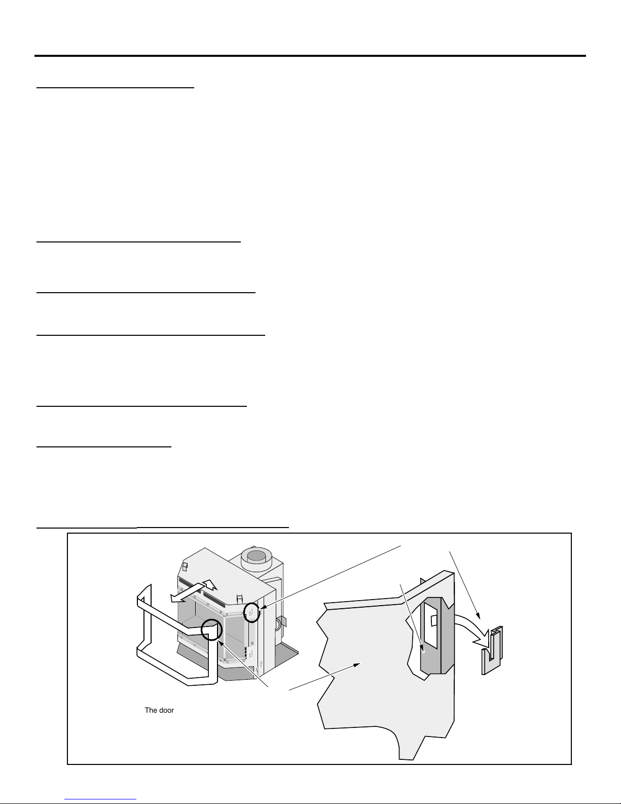
Hooks on Side
of Heater
Bracket (on back
side of door)
The door hangs on a pair of hooks on both
sides. Lift the door up and off the hooks to
remove. To replace, align the brackets on the
door over the hooks and slide downwards until
the door locks in place.
Door
Page 7
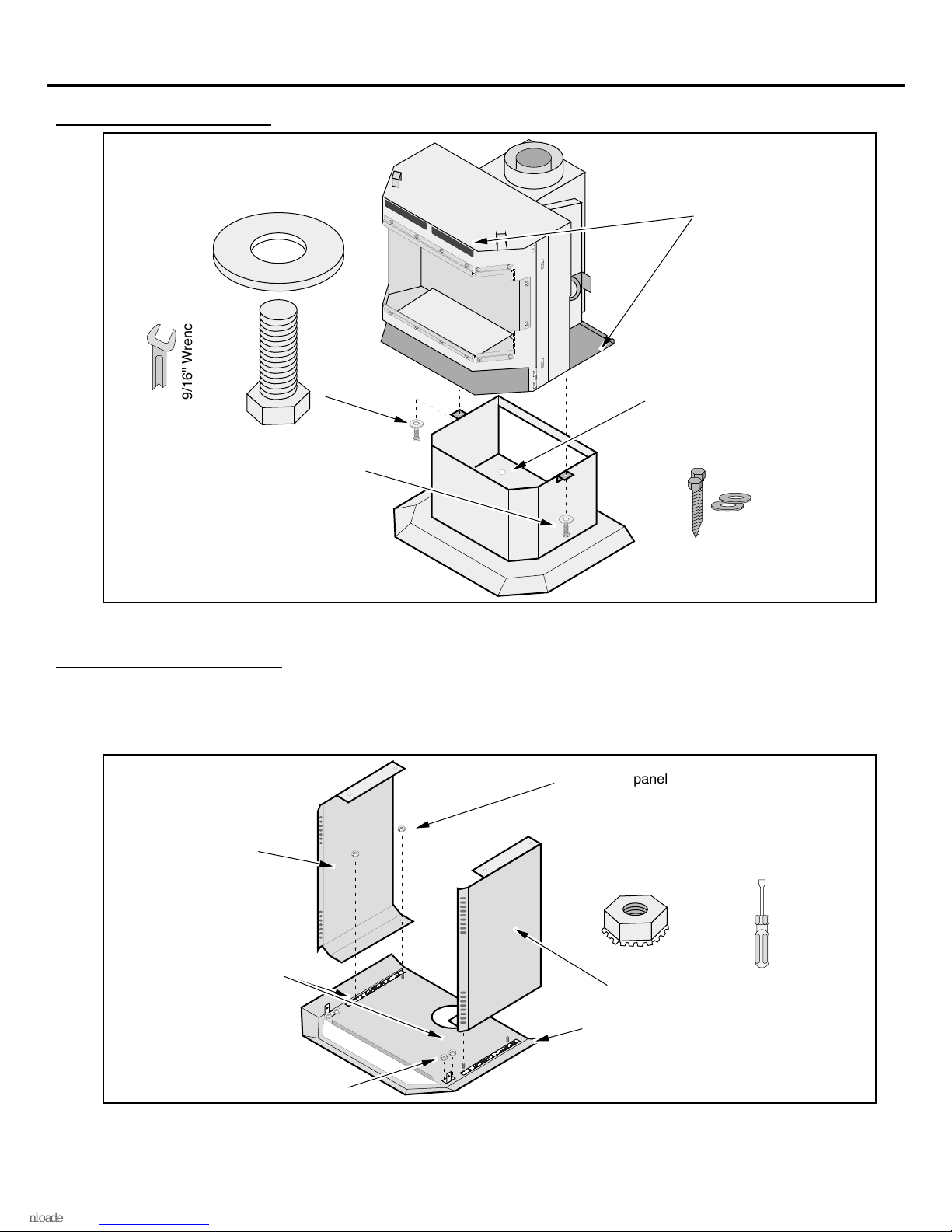
Pedestal Attachment
9/16" Wrench
Use a 9/16" wrench to
attach the two pedestal
bolts to the bottom of the
heater.
INSTALLATION (CONT.) PAGE 7
Lift from here
MOBILE HOME
INSTALLATIONS:
The lag bolts and washers
must be inserted through
these holes to anchor the
pedestal to the floor.
Stove Shell Assembly
1 Place the top panel upside down against a non-scratching surface. Attach the two strips of gasket
along the outside of the two studs on each side. Attach each side panel to the top panel with two 10-
32 lock-washer hex nuts (the smaller of the hex nuts) Ð use a 3/8" nutdriver - DO NOT OVER-
TIGHTEN. Attach each forward mounting bracket with two 10-32 nuts - use a 3/8" nutdriver.
Lay the top panel on a non-scratching
surface upside down. Attach the side
panels to the top panel with the four 10-32
hex nuts (the smaller of the two sizes)
Left side panel
Apply the two 6" long
gaskets along the
outside of the studs
Attach each Forward Mounting
Brackets with two 10-32 nuts.
until the gasket compresses.
Right side panel
Top panel
3/8" Nutdriver
Page 8
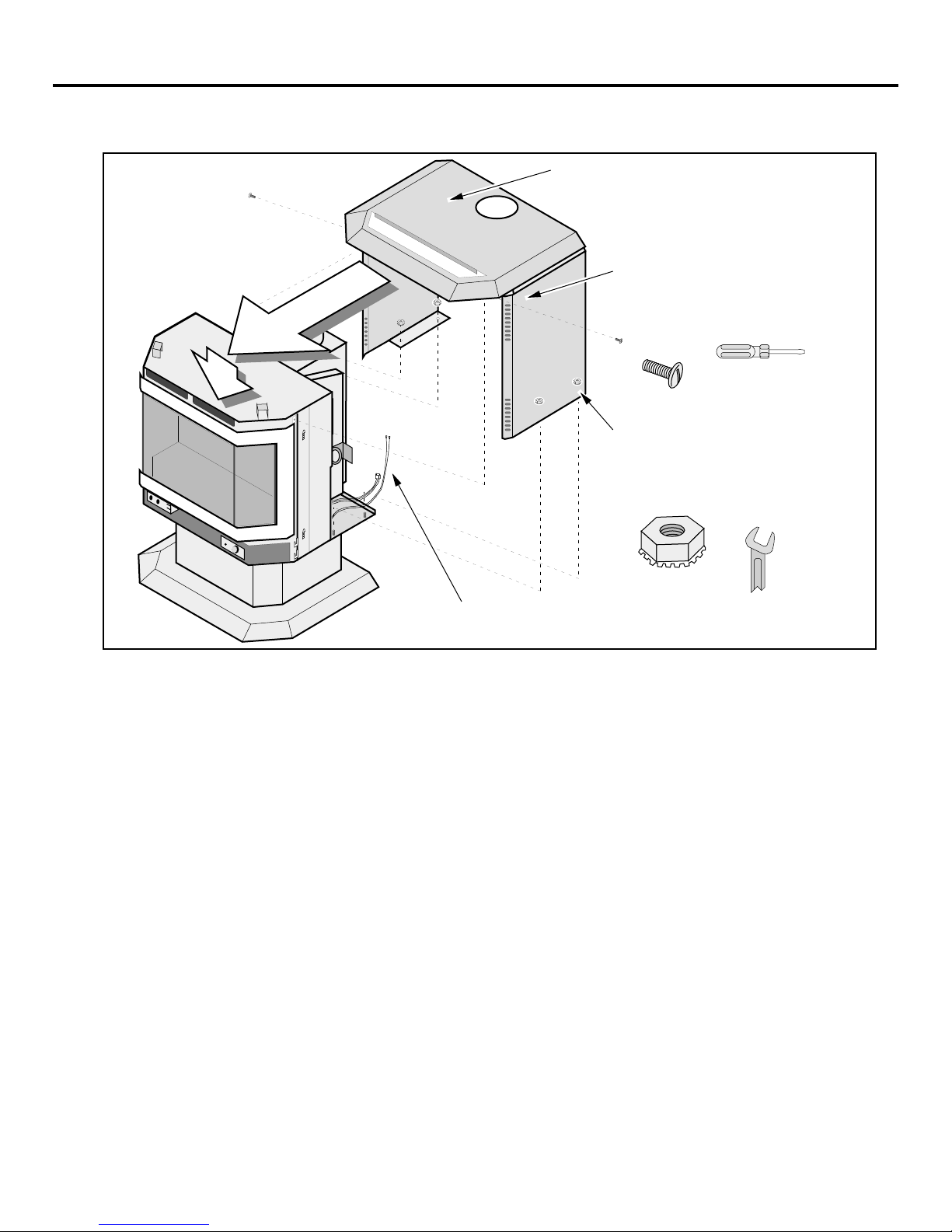
PAGE 8 INSTALLATION (CONT.)
2 Slide the side and top panels onto the stove from the back. Make sure the wires do not get caught
under the side panels. Attach with the four 1/4-20 lock-washer hex nuts and two screws.
Slide the top and side panels into place,
making sure they go underneath the wires
and gas line.
Attach the forward brackets of
the top panel to the heater with
the two black screws.
Standard
Screwdriver
Attach the side panels to the heater
with four1/4-20 hex nuts (reach in
from the rear of the heater with a
7/16" wrench to tighten).
7/16" Wrench
Route the on/off switch and blower
wires to the right rear of the heater.
+ If using a remote control or thermostat, follow the instructions in the optional equipment
section of the owner's manual for attaching the wire prior to attaching the rear panel.
3 Slide the nine U-Nuts into place (see the illustration on the following page).
4 Insert the molex connector on the power cord through the rear panel and attach it to the molex
connector coming from the blower (see the illustration on the following page).
Page 9

INSTALLATION (CONT.) PAGE 9
A
A
A
A
A
A
A
+ Before attaching the rear panel, you need to set the restrictor position. See the section
"Approved Vent Configurations" to determine which restrictor position is required and how
to adjust the restrictor.
5 Attach the on/off switch to the rear panel. Attach the rear panel to the stove and the gas inlet cover
to the rear panel (see the illustration below).
Slide the nine U-Nuts onto the holes
on the top and side panels (with the
flat portion out).
U-Nut
Back of Heater
Jumper Wire
(leave in place)
Detach the two red wires leading to the on/off switch.
Insert the switch into the hole in the upper left of the rear
panel until it locks in place. Then re-attach the two red
wires from the heater to the upper two posts on the switch.
Rear Panel
5/16" Nutdriver
Molex
Connection
Disconnect the power cord at the molex connection and insert it
through the hole in the lower right of the rear panel. Then reattach the power cord to the heater.
Attach the rear panel to the
heater with the twelve 10-24
self-tapping screws. Use a
5/16" nutdriver to tighten.
Page 10
PAGE 10 INSTALLATION (CONT.)
6 Pull gently on the power cord to take out any extra slack. Place the strain relief included with the
stove over the cord and push it into the hole in the rear panel (see the illustration below).
TO INSTALL THE
STRAIN RELIEF
Compress the strain
relief from the top and
bottom and insert it
into the hole until it
locks in place.
Strain Relief
Power Cord
7 Attach the control cover by sliding it over the attachment hooks. Place the black grill in place.
Grill
Gas Inlet Installation
¥ Apply thread sealant to
one end of the gas inlet
and insert it through the
rear panel and into the
90° elbow on the gas
control valve. Tighten
with a pipe wrench.
! Leak check all gas line
connections.
The control cover hangs on two sets of hooks on both sides. Align
the control cover and slide the bracket onto the hooks and then
move downwards.
Control Cover
Bracket on
Control Cover
Insert the gas inlet
into the hole
nearest the center.
NOTE:
Apply thread sealant
prior to installing.
Hooks on Side of Heater
Rear Panel
17-1/4"
Gas Inlet
(3/8" diameter pipe)
Page 11
INSTALLATION (CONT.) PAGE 11
Floor Protection Requirements
¥ When the stove is installed directly on carpeting, vinyl or other combustible material other than
wood flooring, the stove must be installed on a metal or wood protection panel extending the full
width and depth of the pedestal (Minimum 24-1/2" wide by 20" deep).
Stove Placement Requirements & Clearances
¥ The stove must be installed on a level surface capable of supporting the stove and vent
¥ Due to the high temperature of the stove, it should be located out of traffic and away from furniture
and draperies. Stove must be placed so no combustibles are within, or can swing within 36" of the
front of the stove (e.g. drapes, doors)
¥ The stove must not be placed so the vents below or above the door, along the sides of stove, or along
the back of the stove can become blocked.
Alcoves
When placed in a location where the floor to ceiling height is under 7 feet , the installation is
considered an alcove and must meet the following requirements:
¥ The alcove floor to ceiling height must be at least 58" tall
¥ The alcove must not be more than 48" deep (before the ceiling returns to 7 feet)
¥ The alcove must be a minimum of 44-1/2" wide
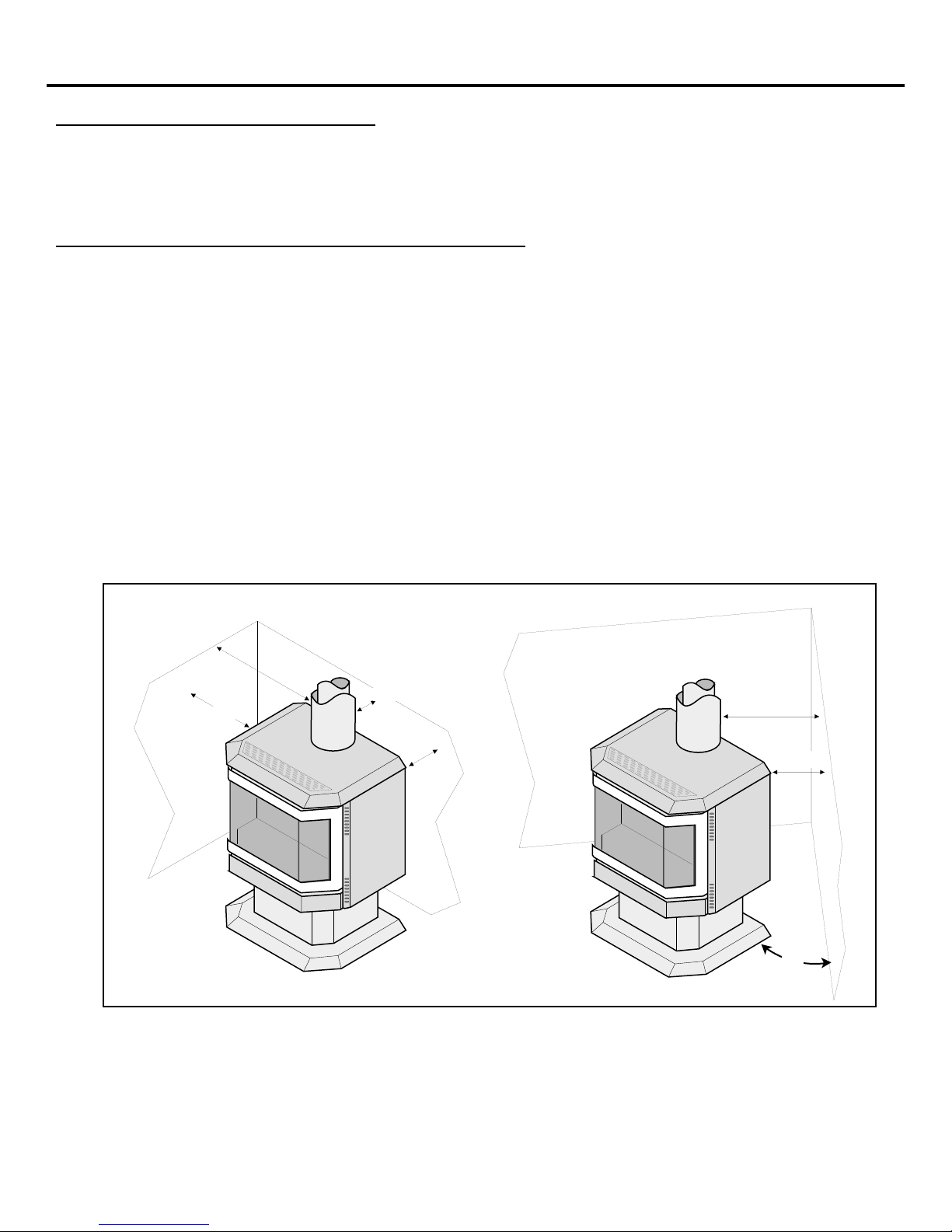
Minimum Clearances
Straight Installations Corner Installations
10" Min.
When installed with
this clearance, the
vent is 4-3/8" from
the back wall, 19"
from the side wall.
3" Min.
When installed with
this clearance, the
vent is 12-5/8" from
the wall.
4" Min.
45¡
+ Clearances may be reduced by methods specified in NFPA 211, listed wall shields, pipe shields, or
other means approved by local building or fire officials.
Page 12
PAGE 12 INSTALLATION (CONT.)
Gas Line Installation
! The gas line must be installed in accordance with all local codes, if any; if not, follow ANSI Z223.1
and the requirements listed below.
! The stove and gas control valve must be disconnected from the gas supply piping during any
pressure testing of that system at test pressures in excess of 1/2 psig. For pressures under 1/2 psig,
isolate the gas supply piping by closing the manual shutoff valve.
¥ The gas line must be properly purged to release all air in the gas line prior to starting the stove.
! We recommend you purge the gas line with the glass removed. This allows gas to be detected once
it enters the firebox, ensuring gas does not build up.
¥ Leak test all gas line joints and the gas control valve prior to and after starting the stove.
Fuel
¥ This stove is designed either for natural gas or
for propane (but not for both). Check the
sticker on the top of the gas control valve to
make sure the correct fuel is used.
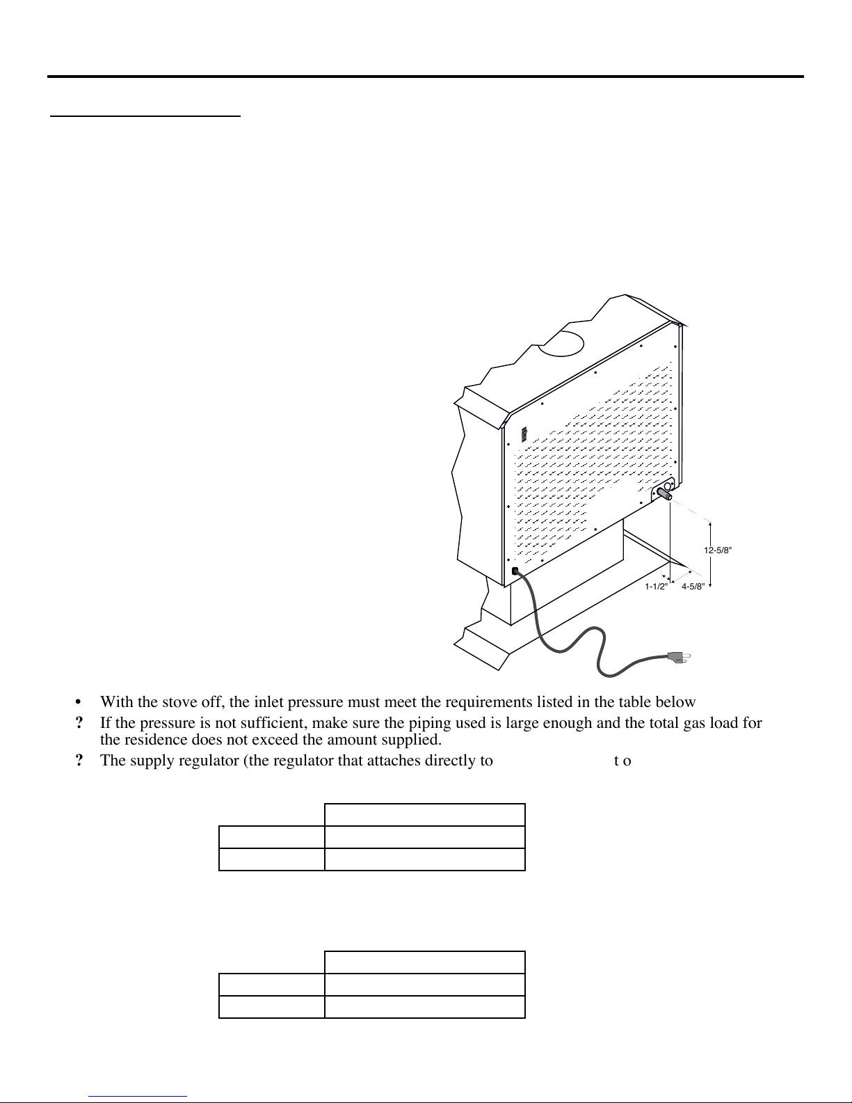
Gas Line Connection
¥ The gas inlet accepts a 3/8" F.P.T. Fitting
¥ The location of the gas inlet is shown below
¥ A manual shutoff valve is required for
installation (it must be located within 3' of the
stove)
12-5/8"
4-5/8"1-1/2"
Gas Inlet Pressure
¥ With the stove off, the inlet pressure must meet the requirements listed in the table below
? If the pressure is not sufficient, make sure the piping used is large enough and the total gas load for
the residence does not exceed the amount supplied.
? The supply regulator (the regulator that attaches directly to the residence inlet or to the propane tank)
should supply gas at the suggested input pressure listed below. Contact the local gas supplier if the
regulator is at an improper pressure.
Minimum Input Pressure
Natural Gas 7" W.C.
Propane 11" W.C.
Manifold Pressure
¥ Gas pressure downstream of the valve may only be checked by removing the manifold pressure tap
with a 3/16" allen wrench (1/8" N.P.T. plug). If the manifold pressure does not match the pressure
listed in the table below, check the inlet gas pressure and correct the problem.
Manifold Pressure on HI
Natural Gas 3.5" W.C.
Propane 11" W.C.
Page 13

INSTALLATION (CONT.) PAGE 13
Vent Requirements
! Always maintain the required 1" clearance (air space) to combustible materials to prevent a fire
hazard. Do not fill air spaces with insulation.
! The gas appliance and vent system must be vented directly to the outside of the building, and never
be attached to a chimney serving a separate solid fuel or gas-burning appliance. Each direct vent gas
appliance must use it's own separate vent system.
! If the stove is installed at an
altitude over 3,000 feet the
flame quality will need to be
carefully evaluated. See
Addendum #1, "Altitude
Considerations", on page 38.
¥ When the vent passes through
a wall, a wall thimble is
required. When the vent
passes through a ceiling, a
support box or firestop is
Use a roof flashing and storm collar
whenever passing through the roof
(Duravent Part #953 & #943 or #943S)
We recommend the use of
the high wind cap (# 991).
Use a firestop spacer whenever
passing through a ceiling
(Duravent Part #963)
Minimum framing
for fire stop
8-5/8"
Use a support box
on exposed vent
Vertical Vent
Requirements
Maintain a minimum 1"
clearance from vent to
any combustible (vent
is 6 5/8" diameter)
required. When the vent
passes through the roof, a
roof flashing and storm collar
are required. Follow the
instructions provided with the
vent (from Duravent) for
8-5/8"
Minimum
Framing for
wall thimble
Use a wall thimble
whenever passing
through a wall
(Duravent Part #940)
Horizontal Vent
Requirements
installing these items.
Maintain a minimum 1" clearance from vent
to any combustible (vent is 6 5/8" diameter)
Horizontal
Termination
¥ Use Model GS Direct Vent manufactured by Simpson Dura-Vent only (or the Chimney Conversion
Kit - see Addendum #2). Follow the installation instructions included with the vent. For the nearest
Simpson Dura-Vent supplier, call (800) 835-4429. Part numbers and descriptions are listed below.
Straight Lengths
908B 6" Pipe Length, Black (interior)
907B 9" Pipe Length, Black (interior)
906 12" Pipe Length, Galvanized
906B 12" Pipe Length, Black (interior)
904 24" Pipe Length, Galvanized
904B 24" Pipe Length, Black (interior)
903 36" Pipe Length, Galvanized
903B 36" Pipe Length, Black (interior)
902 48" Pipe Length, Galvanized
902B 48" Pipe Length, Black (interior)
911B 11" to 14 5/8" Pipe, Adjustable, Black (interior)
Vent Terminations
981 Snorkel Termination (36" rise)
(for basement or raised
termination installations)
982 Snorkel Termination (14" rise)
(for basement or raised
termination installations)
984 Horizontal Square Termination
983 Vertical Termination
950 Vinyl Siding Standoff
991 High Wind Vertical
Termination
Elbows
990 90¥ Elbow
990B 90¥ Elbow, Black (interior)
945 45° Elbow
945B 45° Elbow, Black (interior)
Penetration, Support Parts
940 Round Support Box/Wall Thimble
941 Cathedral Ceiling Support Box
943 Flashing, 0/12 to 6/12 Roof Pitch
943S Flashing, 7/12 to 12/12 Roof Pitch
953 Storm Collar
963 Ceiling Firestop
988 Wall Strap
¥ Apply high-temperature silicone to the male section of inner
pipe (on the lower section of vent) so the silicone seals the
inner pipe from the outer pipe when the sections are
assembled. Slide the sections together and turn 1/4 turn until
the sections lock in place. Install three metal screws through
each joint to lock the outer section in place (see the
instructions included with the vent for further details).
¥ Horizontal sections require a 1/4" rise every 12" of travel
+ Exterior Vent Diameter = 6 5/8", Inner Vent Diameter = 4"
¥ Horizontal sections require non-combustible support every three feet (e.g.: plumbing tape)
Apply a 1/8" bead of
high-temperature
silicone to the inner
Silicone
pipe. The silicone
must seal the inner
pipe from the outer
pipe.
Page 14
PAGE 14 INSTALLATION (CONT.)
Acceptable Vent Configurations
Restrictor Position
¥ A vent restrictor is built into the appliance to adjust the flow rate of exhaust gases. This insures
proper flames for the wide variety of vent configurations. The restrictor consists of a butterfly valve
below the starter section of pipe and an adjustment plate with index holes used to hold the valve in a
fixed position. Depending upon the vent configuration, you may be required to adjust the restrictor
position. The charts for acceptable vent configurations describe which position the vent restrictor
must be in.
Cutaway view of the back of the stove
with the rear panel removed
To Access the Restrictor:
Remove the rear panel. The
adjustment plate is on the right
side (when looking from the rear)
of the starter section of vent.
To Adjust the Restrictor:
1
Determine which position the restrictor should be in (see the
charts under "Acceptable Vent Configurations" - the stock position is #1).
2
Remove the screw with a 1/4" nutdriver (or screwdriver).
3
Rotate the adjustment plate clockwise until the correct index hole is above the pivot point.
4
Insert the screw into the correct index hole and tighten.
Index Holes
Pivot Point
4
5
6
1
2
3
The six holes on
the restrictor
plate correspond
to the six
restrictor
positions
1/4" Nutdriver
Screw
Adjustment
Plate
Rotate the adjustment plate to
change the restrictor position.
This
restrictor is
in Position
#3.
NOTE: Position #1 is the fully open position
Page 15

INSTALLATION (CONT.) PAGE 15
Elbows
¥ 2 Elbow maximum (two 45° or two 90°, not one 45° and one 90°)
Measuring Vent Lengths
Vent Horizontal Run
(measure from the closest
Elbows add 3" to the
length of the vent system.
Side
3"
View
3"
1-1/2"
Vent sections overlap
each other by 1-1/2"
9-5/8"
Vent Height is
calculated to the
top of the vent on
horizontal
terminations and
to the top of the
termination on
vertical
terminations.
edge of the starter section to
the end of the termination)
Starter
Section
9" tall with
1-1/2" of
overlap
Vent Length
1-1/2"
(4', 3', etc.)
EXAMPLE:
Two 4' lengths are 7' 10-1/2" long,
but when attached to the vent system
add 7' 9" to the horizontal run.
Vent
Height
9-1/4" wide
with 1-1/2" to
3-1/4" of overlap
The
starter
section is
32-1/2"
above the
floor
Page 16

PAGE 16 INSTALLATION (CONT.)
Approved Configurations with:
Vertical Termination (No Elbows)
- or -
Verticall Terminations with two 45° Elbows
¥ 10' Minimum Height (with or without offsets)
¥ 33' Maximum Height
¥ 6' Maximum Offset
¥ Use restrictor position indicated by the area that your
termination falls in
Horizontal
Offset
Vertical
Rise
Offset
Length
33 feet
Restrictor
#5
30 feet
25 feet
Restrictor
#4
20 feet
Offset Length Horizontal Offset Vertical Rise
None 5" 1'
1' Section 1' 1' 7"
2' Section 1' 9" 2' 4"
3' Section 2' 5" 3'
4' Section 3' 2" 3' 8"
4' + 1' Section 3' 9" 4' 4"
4' + 2' Section 4' 6" 5'
4' + 3' Section 5' 2" 5' 9"
4' + 4' Section 6' 6' 9"
15 feet
10 feet
(min. height)
5 feet
0 feet
6 feet
Page 17

INSTALLATION (CONT.) PAGE 17
A
A
A
A
A
A
Approved Configurations with a Horizontal Termination (using one 90° elbow)
¥ 16' Maximum Horizontal Run
¥ 16' Maximum Height
¥ If using a Snorkel Termination (14" or 36") add the snorkel height to the vertical height.
¥ Use restrictor position indicated by the area that your termination falls in
15 feet
10 feet
5 feet
0 feet
5 feet
10 feet
AAAAAAAAAAAA
Restrictor Position # 4
AAAAAAAAAAAA
AAAAAAAAAAAA
AAAAAAAAAAAA
Restrictor Position # 3
AAAAAAAAAAAA
AAAAAAAAAAAA
Restrictor Position # 1
15 feet
16 ' (max.)
15 feet
10 feet
5 feet
0 feet
0 feet
NOTE: Horizontal sections require a 1/4" rise every 12" of travel.
5 feet
10 feet
16 '
15 feet
0 feet
(max.)
Page 18

PAGE 18 INSTALLATION (CONT.)
A
A
A
A
A
A
A
A
A
A
A
A
Approved Configurations with a Vertical Termination and Two 90° Elbows
¥ 16' 5" Maximum Horizontal Run (4' 10" if the vertical rise is over 27' 9")
¥ 33' 5" Maximum Height (27' 9" if horizontal run is over 4' 10")
¥ Use restrictor position indicated by the area that your termination falls in
Restrictor
Position # 5
33' 5" (max)
30 feet
25 feet
20 feet
0 feet
Restrictor
Position # 4
5 feet
10 feet
AAAAA
AAAAA
AAAAA
AAAAA
AAAAA
AAAAA
Restrictor
AAAAA
Position # 3
AAAAA
15 feet
16' 5" (max)
30 feet
25 feet
20 feet
15 feet
10 feet
(min.)
5 feet
0 feet
0 feet
AAAAA
AAAAA
AAAAA
AAAAA
AAAAA
NOTE: Horizontal sections
require a 1/4" rise every 12"
of travel.
5 feet
10 feet
15 feet
10 feet
(min.)
5 feet
0 feet
15 feet
Page 19

INSTALLATION (CONT.) PAGE 19
C
Horizontal Vent Termination Requirements (see the illustration below)
¥ The horizontal vent termination (standard or snorkel) must meet the following requirements:
A Minimum 12" clearance to any door or window (9" if the window may not be opened)
B Minimum 12" above any grade, veranda, porch, deck or balcony
C Minimum 12" from outside corner walls
D Minimum 24" from inside corner walls
E Minimum 18" clearance below a soffit (eaves or overhangs) (24" for vinyl covered surfaces)
F Minimum 18" clearance below a veranda, porch, deck or balcony (must have two open sides)
G Minimum 48" clearance from any adjacent building
H Minimum 84" clearance above any grade when adjacent to public walkways or driveways
NOTE: may not be used over a walkway or driveway shared by an adjacent building
I Minimum 36" clearance from any mechanical air supply inlet
J Minimum 12" clearance from the top and sides or 36" below any non-mechanical air supply inlet
K Minimum 36" from the area above the meter/regulator (vent outlet)
L Minimum 36" from the meter/regulator (vent outlet)
E
A
A
G
NOTE: Measure all clearances from the center of the exhaust vent.
F
D
K
I
C
L
B
J
¥ Use the vinyl siding standoff (#950) when installing on an exterior with vinyl siding.
¥ Vent termination must not be located where it will become plugged by snow or other material
Vertical Vent Termination Requirements (see the illustration below)
U.S. Min.
Height (feet)
1
1.5
2
2.5
3.25
4
5
6
7
7.5
8
Use the
chart to the
right to
determine
the required
vent
termination
height.
Roof
Pitch
Height
Use the
vertical vent
termination
(#983)
Roof Pitch
Flat to 7/12
7/12 to 8/12
8/12 to 9/12
9/12 to 10/12
10/12 to 11/12
11/12 to 12/12
12/12 to 14/12
14/12 to 16/12
16/12 to 18/12
18/12 to 20/12
20/12 to 21/12
H
+ Travis Industries highly
recommends the high wind
vertical termination in all
installations (part # 991).
Electrical Connection
¥ Plug the power cord into a grounded 110 Volt outlet (do not remove the grounding plug).
Standard Vertical Termination (#983)
High-Wind Vertical Termination (#991)
Page 20

PAGE 20 INSTALLATION (CONT.)
Glass Removal
Center
Glass
Loosen all of the nuts
A
that hold the glass clips
against the glass.
Loosen two turns.
Right
Side
Glass
5/16" Nutdriver
Glass
Trim
Center
Glass
Slide the right side
B
glass to the right
until the glass trim
can be removed.
Right
Side
Glass
C
Right
Side
Glass
Slide the
center
glass out
Slide the side
D
pieces of glass out
+ If switching the burner pan to propane (LP), do so now.
+ We recommend you purge the gas line at this time (with the glass removed). This allows gas to be
detected once it enters the firebox, ensuring gas does not build up.
Page 21

Log and Ember Installation
Pilot Assembly
Burner Pan
Front Log
Rear Log (largest)
INSTALLATION (CONT.) PAGE 21
The rear log has a flat portion
that rests on this ledge
The front log has two slots that
straddle the clips on both sides
(push the log all the way back).
The right twig has a hole for
the pin on the left twig.
The left twig has two holes to accept
the pins in the front and rear log.
When in place, the
logs look like this.
Right Twig
Left Twig
Place the twig so the lower
branch rests inside this channel.
Place the coals on this ledge at the front of the firebox .
Do not place the coals over the burner holes.
Page 22

PAGE 22 INSTALLATION (CONT.)
Glass Installation
Install the glass by following the instructions on page 20 in reverse order. NOTE:
¥ The glass clips should be in place with the nuts threaded two turns onto the attachment studs.
¥ The gasket must be pliable and follow the perimeter of the firebox opening.
¥ After the glass and trim is in place, align the glass so it is centered and the pieces of glass insert
fully into the trim
¥ Tighten the glass clips on the center piece of glass first.
Cross Section of Glass Attachment
Glass Clip
Attachment Studs
Face of Heater
NOTE:
Make sure the gasket is not
pinched underneath the glass clip.
Glass Clip Nuts
(use a 5/16" nutdriver
to remove)
NOTE:
If the gasket does not stay in place,
use stove gasket cement to re-attach
or use a new gasket.
Glass Gasket
(5/8" self-adhesive gasket)
5/16" Nutdriver
Glass Clip
Glass
Door Installation
Place the door on the stove (see page 6 for details).
! Clean the door with a soft piece of cloth and denatured alcohol. Other cleaners may leave a film.
Marks left on the gold may become etched in place if not cleaned before starting the stove.
Leak, Pilot, and Flame Testing
! Leak test all gas line joints leading to the gas control valve. Correct any leaks. Start the pilot flame
and main burners (see the directions on page 25 & 26 if uncertain). Leak test all gas line joints
leading from the gas control valve to the burner pan. Correct any leaks. Turn the flame adjust knob
to its highest position - the flames should be a between 8" and 11". Check the flame on low position.
The flames should burn off of each burner hole. Turn the main burner off and check the pilot flame
to make sure it burns correctly (see the picture on page 28).
Page 23

INSTALLATION (CONT.) PAGE 23
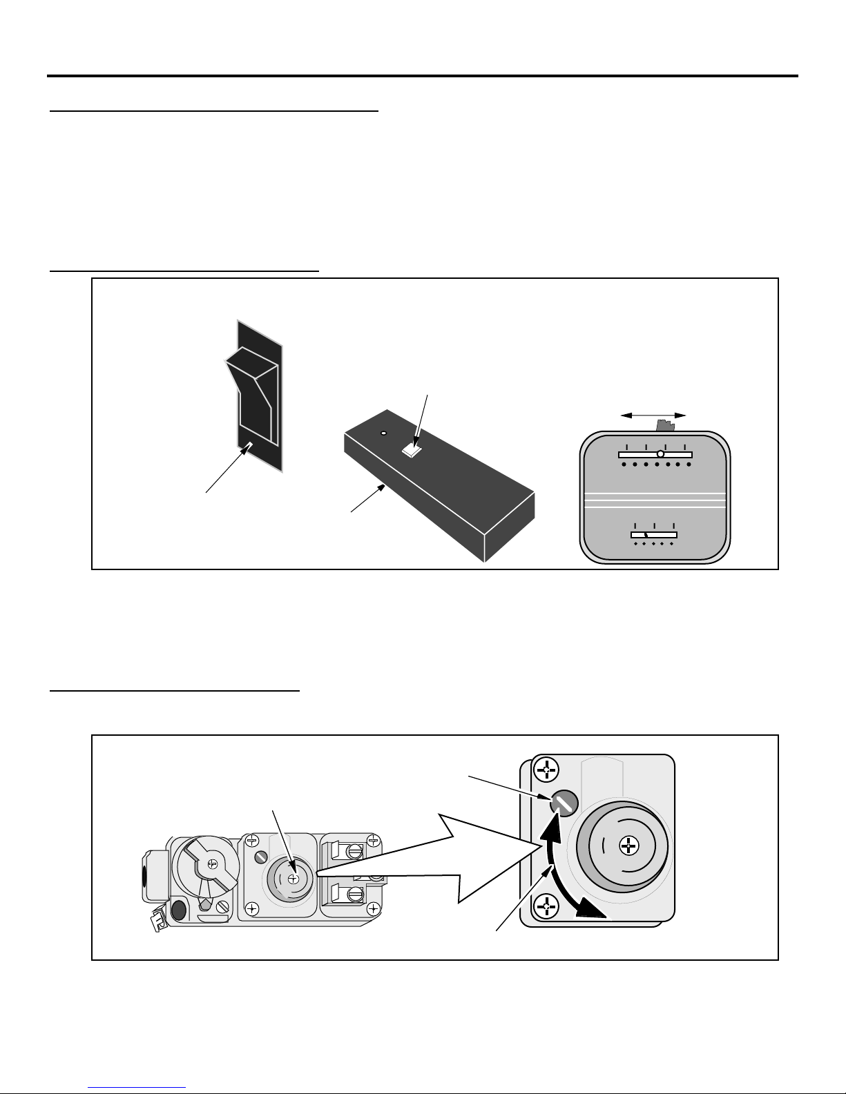
¥ Let the stove burn for fifteen minutes. Adjust the air shutter, if necessary, to achieve the correct
looking flame (see the illustration below). The air shutter adjusts the amount of air that mixes with
the gas before it exits the burner holes. It is used to fine-tune the flame for differences in altitude
and vent configuration.
Locate the air shutter adjustment
lever behind the gas control valve.
Move it up or down until the flame
looks correct. Pushing up gives the
flame more air (making it bluer).
Pulling it down cuts air down,
making it more orange.
NOTE: If the air control is all the
way up, yet the flames remain
sooty, shut off gas to the fireplace
and contact a qualified gas service
technician.
T
ON
O
PILOT ADJ
L
Gas Control Valve
OFF
P
I
VENT
HI
LO
NOTE: The logs must be installed correctly to
monitor the flame while adjusting the air shutter.
Correct
Flames should be blue at the
base, yellow-orange on the top.
If the flames are over 12" tall or sooty
on the ends, push up on the lever.
Not Enough Air Too Much Air
If the flames are all blue and
short, pull down the lever.
! If the air shutter is in its fully open position, yet the flames remain sooty, shut off gas to the stove
and contact your Travis Industries Dealer for a remedy.
! If the vent configuration is installed incorrectly the vent may cause the flames inside the stove to lift
or "ghost" Ð a dangerous situation. Inspect the flames after installation to insure proper performance.
If the vent configuration is correct, yet the flames are lifting or ghosting, shut off gas to the stove and
contact the dealer for information on remedying the problem.
Burner Ports
(consists of slots
Burner Pan
The flames should burn right off
the top of the burner ports (if they
are too blue, adjust the air control).
If the flames are lifting, yet the
vent configuration is correct,
contact your dealer.
and holes)
If the flames are ghosting, yet the
vent configuration is correct,
contact your dealer.
¥ Give this manual to the home owner and fully explain the operation of this stove.
Page 24

PAGE 24 OPERATING YOUR HEATER
Before You Begin
! Read this entire manual before you use your new stove (especially the section "Safety
Precautions" on pages 2 & 3). Failure to follow the instructions may result in property
damage, bodily injury, or even death.
Location of Controls - See explanation below
Gas
Control
Valve
T
O
PILOT ADJ
ON
ON/OFF Switch
TO ACCESS THE CONTROLS:
Grasp the control cover with both hands and
lift it up and off the hooks that hold it in place.
Place it on a non-scratching surface.
The on/off switch is located on the
rear panel.
PILOT
OFF
HI
O
N
O
F
F
IGNITER
LO
BLOWER
VENT
OFF
P
I
L
HI
LO
The Pilot Flame can be
found below the front log
on the left side.
Pilot Igniter
Blower Knob
Gas Control
Knob
Flame Adjust
On/Off Switch This control is used to turn the main burner on and off.
Gas Control Knob This knob is used to control gas to the stove and for starting the pilot. There
are three positions, ON, OFF, & PILOT. The pointer directly below the knob
indicates the position this knob is in.
Flame Adjust Knob This knob controls the flame height from low ("LO") to high ("HI"). The
pointer to the upper right of the knob points to the position this knob is in.
Pilot Igniter The pilot igniter is used only to start the pilot. When pressed, it sends an
electrical charge to the pilot assembly. This creates a blue spark directly next
to the pilot, igniting the pilot flame.
Blower Knob This knob controls the speed of the internal convection blower that pushes the
heated air into the room.
? If using a remote control or thermostat, the On/Off Switch must be left "ON". Turning the On/Off
Switch "OFF" will keep the stove off always.
Knob
Page 25

Starting The Pilot Flame
The pilot flame is required to ignite the main burners (it also plays a safety role). It should be
left on once lit. It will stay lit unless the gas control valve is turned to "OFF". However, the
pilot will go out if the gas is shut off or if the stove malfunctions. If the pilot turns off
frequently, call your dealer for information. To start the pilot follow the directions below:
OPERATING YOUR HEATER (CONTINUED) PAGE 25
A Push the gas control
knob in slightly and turn
it to the "OFF" position.
The knob will not turn
from "ON" to "OFF"
unless the knob is
depressed slightly.
B Wait five minutes to let
any gas that may have
accumulated inside the
firebox escape. If you
smell gas, follow the
directions on the cover
"IF YOU SMELL GAS".
C Turn the gas control
knob to the "PILOT"
position and press the
knob in, this will allow
gas to flow to the pilot
light. Press the red
button on the pilot
igniter repeatedly until
you see the pilot light.
KEEP THE GAS
CONTROL KNOB
DEPRESSED FOR 30
SECONDS ONCE IT IS
LIT. Note: If the pilot
does not light after
several tries, call your
dealer for service.
AB
T
O
L
I
ON
OFF
P
PILOT ADJ
5 minutes
C
ON
T
O
PILOT ADJ
ON
T
O
PILOT ADJ
L
L
OFF
P
I
OFF
P
I
PILOT
IGNITER
30 seconds
D Release the gas control
knob. If the pilot goes
out, repeat step C. If the
pilot refuses to stay lit,
call your dealer for
service.
E Turn the gas control
knob counter-clockwise
to "ON". The pilot is
now lit and the stove can
be turned on and off.
D
ON
T
O
PILOT ADJ
L
OFF
P
I
?
E
P
OFF
ON
PILOT ADJ
I
L
O
T
Page 26
PAGE 26 OPERATING YOUR HEATER (CONTINUED)
PILOT ADJ
Starting the Stove for the First Time
+ Fumes and smoke from the paint curing and oil burning off the steel may occur the first time you
start your stove. This is normal. We recommend you open windows to vent the room.
+ Condensation may appear on the glass each time you start the stove - this is normal.
+ Blue Flames will occur on the stove when it first comes on. After fifteen minutes the flames will
turn a more realistic yellow and orange color.
? Certain installations use a remote "wall switch" to turn the stove on and off. If this is the case, leave
the ON/OFF switch "ON".
Turning the Stove On and Off
After the pilot has been started...
For systems with thermostats,
use this switch to control the
temperature (right is hotter, left
cooler). Some systems
require the on/off switch to be
on.
O
N
O
Use this switch to
turn the main burner
on and off manually.
F
F
See the optional
equipment instructions
for installing the battery.
For systems with remotes,
make sure the On/Off Switch
shown to the left is on. Then
use this button here to turn the
main burner on and off.
! Do not place any combustible items on top of or directly in front of the stove, even temporarily. The
optional thermostat may start the stove causing a combustible item to ignite.
? If the stove turns on and off frequently while using the thermostat, you may want to adjust the flame
height down until it produces just enough heat needed.
Adjusting the Flame Height
+ Your stove has an adjustable flame to tailor the look and heat output to your specific needs. It is
adjusted by turning the middle dial on the gas control valve.
Flame Height
Adjustment Knob
ON
OFF
T
P
O
L
I
Index Mark
VENT
HI
VENT
HI
LO
Turn clockwise to adjust the flame higher, counter-clockwise to lower.
LO
Page 27

OPERATING YOUR HEATER (CONTINUED) PAGE 27
Adjusting the Blower Speed
+ The blower helps transfer the heat from the stove into the room. It will not turn on until the stove is
up to temperature (approximately 10 minutes after starting). See the illustration below for
instructions on adjusting the blower speed.
PILOT
IGNITER
LO
Normal Operating Sounds
Pilot Flame
The pilot flame,
which remains on,
makes a very slight
"whisper" sound.
OFF
HI
Blower Knob
Turn the knob all the way counter-clockwise to turn
the blower off. One click clockwise turns the
blower to high speed. Turning the knob clockwise
from the high position decreases the speed of the
BLOWER
blower.
Blower
This heater uses a blower to push
heated air into the room. You will hear
the sound of air movement that
increases as the speed is increased.
The appliance will
creak with change of
temperature.
Gas Control Valve
As the gas control
valve is turned on
and off you will hear
a dull clicking
sound. This is the
valve opening up
and shutting down.
Blower Snap Disk
This part can
produce a clicking
sound as it turns the
blower on and off.
Page 28

PAGE 28 MAINTAINING YOUR HEATER
Maintaining Your Stove's Appearance
! The enameled surfaces may chip if struck. Damaged surfaces may be repaired using the enamel touch-up paint available
from Your Dealer
! Fingerprints or other marks left on the gold surface may become etched in place if they are not wiped clean prior to
turning the stove on. Clean the surfaces with denatured alcohol and a soft cloth.
¥ Enameled surfaces may be cleaned with a soft rag and water. Do not use any other cleaning materials.
Yearly Service Procedure
! Failure to inspect and maintain the stove may lead to improper combustion and a potentially dangerous situation. We
recommend the following procedures be done by a qualified technician.
1 Check the pilot flame. It should engulf approximately 3/8" of the top of the thermopile and engulf the top of the
thermocouple (see illustration below). If it does not, contact your dealer for service.
2 Shut off gas to the stove by turning the gas control knob to "OFF" (see step A under "Starting the Pilot" on page 25). Let
the stove cool for 15 minutes. Remove the door (see page 6) and glass (see page 20).
3 Remove the log set (see page 21). If any log is cracked or deteriorated, replace it when re-installing. Check the logs for
sooting. A small amount of soot along the bottom of the logs is normal. If excessive sooting is found, the stove will
require adjustment. Contact your dealer.
4 Clean the burner pan (especially in the burner holes and slots) and inspect the following:
¥ Check for burner pan holes that are cracked, severely warped, or corroded.
¥ Make sure the burner pan assembly fits flat against the floor of the firebox.
¥ Check the firebox and area around the pilot to make sure there is no warping or damage.
If any problem is found, discontinue use and contact your dealer for service.
Before dissassembly, check the pilot flame. It should
engulf approximately 3/8" of the thermopile and engulf
the top of the thermocouple.
Thermopile
Check the burner
holes and slots.
Thermocouple
Make sure the burner pan seals
against the floor of the firebox.
Burner Pan
Check the walls and
ceiling of the firebox
for deterioration.
5 Replace the log set. Replace the glass (use a new gasket - if the glass is damaged, replace it). Make sure the gasket
along the perimeter of the glass contacts the face of the firebox and forms an air-tight seal. If it does not, re-align or
replace the gasket to insure an air-tight seal. Replace the faceplate.
6 Inspect the area behind the control cover. Check the gas control valve and all of the gas lines. If any damage is found,
discontinue use and contact your dealer for service.
7 Start the pilot and turn on the main burner. The flames should be orange/yellow and not touch the top of the firebox. If
the pilot or main burners do not burn correctly, contact your dealer for service. Monitor the blower operation. If it
makes excessive noise, contact your dealer for an evaluation.
8 Remove any debris or vegetation near the vent termination. Contact your dealer if any sooting or deterioration is found
near the vent termination.
Page 29

TROUBLESHOOTING PAGE 29
Problem: Possible Cause: Don't Call for Service
Until You:
Pilot Will Not Flame A gas shut off valve is turned off
The gas control knob isn't turned to "PILOT"
The valve control knob isn't pushed in
The igniter wasn't pressed repeatedly
Main Burners Will Not
The pilot flame has gone out
Start
The gas control valve is turned to "PILOT" or "OFF"
The ON/OFF switch is turned to "OFF"
The remote control is not working correctly
The thermostat is disconnected or set too high
Remote Control Does
The pilot light has gone out
Not Work
The gas control valve is turned to "PILOT" or "OFF"
The ON/OFF switch is turned to "OFF"
The remote is too far away from the stove
Check all gas shut off valves
See "Starting the Pilot Flame" Pg 25
See "Starting the Pilot Flame" Pg 25
See "Starting the Pilot Flame" Pg 25
See "Starting the Pilot Flame" Pg 25
See "Starting the Pilot Flame" Pg 25
Turn the ON/OFF switch to "ON"
Replace the batteries
Set the thermostat to a lower temperature
See "Starting the Pilot Flame" Pg 25
See "Starting the Pilot Flame" Pg 25
Turn the ON/OFF switch to "ON"
Use the remote closer to the stove
Thermostat Does Not
Work
Blower Does Not
Operate
Flames Are Too Blue
Flames Are Too Short
(Under 6")
The remote control receiver is turned "OFF"
One of the two remote control batteries is dead
The pilot flame has gone out
The gas control valve is turned to "PILOT" or "OFF"
The ON/OFF switch is turned to "OFF"
The thermostat is set too high
The stove is not getting electricity
The stove is not up to temperature
The stove has just been started This is normal - see "Starting the Stove for
The flame height may be turned too low Turn the flame height to "HI" -
Switch receiver to "ON" or "REMOTE"
See "Remote Control Operation"
See "Starting the Pilot Flame" Pg 25
See "Starting the Pilot Flame" Pg 25
Turn the ON/OFF switch to "ON"
Set the thermostat to a lower temperature
Check the outlet switch
See "Operating Your Stove"
the First Time"
See "Adjusting the Flame Height"
Page 30

PAGE 30 TROUBLESHOOTING (CONTINUED)
How this Stove Works
! This stove was designed with safety as the primary concern. Many of the components inside this
stove are for safety purposes. Therefore, only certified gas service technicians should service this
stove.
What Turns the Main Burners On and Off
This stove uses a millivolt system to control its operation (a millivolt is a very small amount of
electricity). The thermopile and thermocouple generates electricity when heated by the pilot flame.
This electricity is used to operate the gas valve. Without enough electricity, the gas valve will not
turn on. That is why when starting the pilot the gas control knob has to be pressed in long enough
for the thermocouple to heat up and generate enough electricity. The thermopile provides power for
the ON/OFF switch, remote control, or thermostat (see the illustration below). Because the
thermopile generates the electricity needed to turn the stove on and off, this stove can be operated
when the power is out (although the blower will not run).
When heated, the thermopile
generates electricity (a very small
amount, measured in "Millivolts").
This electricity is
used to operate the
main burners.
The main burners
are switched on and
off using the
electricity generated
ON
VENT
OFF
T
HI
LO
P
I
O
L
PILOT ADJ
by the thermopile.
The ON/OFF switch,
remote control, or
thermostat control
the circuit to the main
burner.
NN
OOOONN
RR
RR
EE
EE
NN
NN
RR
RR
UU
UU
BB
BB
NN
NN
II
II
AA
AA
FF
OOOOFFFFFF
MM
MM
What Prevents Gas Buildup
+ This appliance utilizes a high-technology gas valve in conjunction with a pilot flame to ensure no
gas builds up inside the firebox.
+ While the main burner is off the thermocouple (next to the pilot) senses when the pilot flame is lit.
If the pilot flame goes out, this thermocouple no longer generates electricity, causing the gas valve to
automatically shut off all gas to the stove, preventing the pilot from spilling gas into the firebox.
+ While the main burner is on the pilot flame insures all gas ignites inside the firebox.
Pilot Flame
The pilot flame is a time-proven
component that eliminates the possibility
of gas buildup inside the firebox.
Gas Valve
This high-technology valve automatically
shuts off all gas if it does not receive a signal
from the thermocouple. If any component is
damged or sensing a malfunction, or if the
wiring is damaged, it will shut off all gas.
ON
VENT
OFF
HI
P
T
O
PILOT ADJ
LO
L
I
External Shut Off Valve
This valve is placed on the gas line
to shut off gas to the appliance
during maintenance procedures.
Therocouple
The thermocouple generates a small
amount of electricity. If the pilot flame
goes out, the gas valve automatically
shuts off all gas.
Ceramic Glass
The glass in your heater is the most
durable glass available. It has been
tested to be extremely resistant to
breakage and temperature changes.
Page 31

TROUBLESHOOTING (CONTINUED) PAGE 31
Why Nothing Should Be Placed Against the Stove
For safety and operation purposes, do not place any object against the appliance.
Wiring Diagram
Green
Jumper Wire
(Manual
Operation)
Optional
Thermostat
EPU
terminal
Green
Optional
Remote
Control
Blower
Motor
Black
Black
Red
On/Off
Switch
Black
Black
Thermopile
White
Chassis
Ground
White
White
White
Red
Green
Piezo Igniter
Thermocouple
120 Volt
Grounded A.C.
Power Supply
Black
Orange
Red
Blower
Thermodisk
Blower
Rheostat
Replacement Parts List
Replacement parts are available at your dealer. Contact Travis Industries for information on the
closest dealer. The parts listed below are the only parts that the consumer may replace. All other
parts must be replaced by a qualified gas service person.
PART Part description
Glass Gasket Black 5/8" wide, 1/8" thick Self-Adhesive Fiberglass
Door Glass 5 mm neoceram - 3 pieces
Glass Clips 6 Clips
Log Set (includes coals) Front and back log, left and right twig, and coals
Owner's Manual This document
Black
Page 32

PAGE 32 WARRANTY
TRAVIS INDUSTRIES, INC. warrants the AVANTI DV gas appliance to be defect-free in material and workmanship for five (5) years
from the date of purchase, with the exception of the porcelain enamel finish, gold finish, glass, paint, electrical components, switches, piezo
igniter, fans, gaskets, logs, moving parts, gas valve, manifold, and burner pan. This does not include service call cost or any other
additional charges. Check with your dealer for all costs if arranging a warranty call. The exceptions listed are warranted for one (1) year
from the date of purchase to be defect-free in material and workmanship, with the exception of the porcelain enamel finish, gold finish,
glass and paint, which are not covered by the warranty.
Exclusions to this limited warranty include: Injury malfunction to the product, loss, damage, defect, failure to function due to accident,
negligence, misuse, improper installation, alteration or adjustment of the manufacturers settings of components, lack of proper and regular
maintenance, damage incurred while the unit is in transit, alteration, or act of God.
This limited warranty excludes damage caused by normal wear and tear, such as paint discoloration or chipping, worn or torn gasketing,
eroded or cracked logs, ember strip, etc. Also excluded is damage to the unit caused by abuse, improper installation, modification of the
unit, drilling of the orifices, or the use of fuel other than that indicated on the safety label (natural gas or propane).
TRAVIS INDUSTRIES, INC. is free of liability for any damages caused by the unit, as well as inconvenience expenses, material and labor
charges incurred by the removal or reinstallation of any AVANTI DV unit. Incidental or consequential damages are not covered by this
warranty. In some states, the exclusion of incidental or consequential damage may not apply.
This warranty does not cover any loss or damage incurred by the use or removal of any component or apparatus to or from the AVANTI
DV unit without the express written permission of TRAVIS INDUSTRIES, INC. and bearing a TRAVIS INDUSTRIES, INC. label of
approval.
Any statement or representation of AVANTI DV products and their performance contained in AVANTI DV advertising, packaging
literature, or printed material is not part of this limited warranty.
This warranty is automatically voided if the unitÕs serial number has been removed or altered in any way.
Only the original purchaser of an AVANTI DV stove is covered by this warranty. If the unit is used for commercial purposes, it is
excluded from this warranty.
No dealer, distributor, or similar person has the authority to represent or warrant AVANTI DV products beyond the terms contained within
this warranty. TRAVIS INDUSTRIES, INC. assumes no liability for such warranties or representations.
THIS LIMITED WARRANTY IS THE ONLY WARRANTY SUPPLIED BY TRAVIS INDUSTRIES, INC., THE MANUFACTURER
OF THE UNITS. ALL OTHER WARRANTIES, WHETHER EXPRESS OR IMPLIED, ARE HEREBY EXPRESSLY DISCLAIMED
AND PURCHASERÕS RECOURSE IS EXPRESSLY LIMITED TO THE WARRANTIES SET FORTH HEREIN.
This warranty is limited to the time frame set forth above. In some states, time limitations on warranties do not apply.
HOW TO USE YOUR AVANTI DV FIVE-YEAR WARRANTY: If you find your unit to be defective in workmanship or material within
a 5-year period from the date of purchase contact your local authorized AVANTI DV dealer. If your dealer is unable to repair your unitÕs
defect, he may process a warranty claim through TRAVIS INDUSTRIES, INC., including the name of the dealership where you purchased
the unit, a copy of your receipt showing the date of the unitÕs purchase, and the serial number on your unit. At that time, you will be asked
to ship your unit, freight charges prepaid, to TRAVIS INDUSTRIES, INC. TRAVIS INDUSTRIES, INC., at its option, will repair or
replace, free of charge, your AVANTI DV unit if it is found to be defective in material or workmanship within the time frame stated within
this limited warranty. TRAVIS INDUSTRIES, INC. will ship your unit, freight charges prepaid by TRAVIS INDUSTRIES, INC., to your
regional distributor, or dealership.
To register your TRAVIS INDUSTRIES, INC. Five-Year Warranty, complete the enclosed warranty card and mail it within ten (10) days
of the unit purchase date to: TRAVIS INDUSTRIES, INC., 10850 117th Place N.E., Kirkland, Washington 98033.
OTHER RIGHTS:
This warranty provides you with certain legal rights. You may have additional rights, which vary from state to state, in regards to this
warranty.
Unit Serial Number
Date of Purchase
Dealer Name and Address
Travis Industries, Inc. reserves the right to change, without notice, product features or specifications described.
10850 117th Place N.E. Kirkland, WA 98033
Complete and
save for your
records
Page 33
LISTING INFORMATION PAGE 33
The safety label can be found on a card that is chained to the unit behind the control cover. A copy is shown
below.
Warnock Hersey
AAAAvvvvaaaannnnttttiiii DDDDVV
Tested to ANSI Z21.446-1993 "Gas-Fired Direct Vent Wall Furnace", CAN/CGA IR #41, CAN/CGA #55, and
CAN/CGA-2.17-M91 "Gas-Fired Appliances for use at High Altitudes" (Report #1198, September, 1995)
Must be installed in accordance with all local codes, if any: if not, follow ANSI Z223.1-1992, NFPA 54(88), the
Manufactured Home Construction and Safety Standarad, Title 24 CFR, Part 3280, or the Canadian CAN1-B149
Installation Code and the requirements listed in the accompanying owner's manual.
WARNING:
Use Simpson Dura-Vent direct vent system (model GS) to vent this appliance to the exterior (direct discharge only
without duct connection).
Improper installation, adjustment, alteration, service or maintenance can cause injury or property damage. Refer
to the information in the owner's manual provided with this appliance. For assistance or additional information
consult a qualified installer, service agency or the gas supplier.
Risk of electrical shock. Switch the household breaker off or remove fuse before servicing unit.
Fan Type Vented Circulator
Blower Electrical Rating: 115 V., 1.5 Amps, 60 Hz, 150 watts
Thermal Efficiency.......... 81.5% (natural gas) 83.3% (propane)
Output Capacity Rating... 25,265 (natural gas) 25,823 (propane)
Listed Gas-Fired Direct Vent Wall Furnace
VV
Manufacture
Date:
1995
1996
1997
WH-
Jan.
Feb.
Mar.
Apr.
May
Jun.
Jul.
Aug.
Sep.
Minimum Clearances to Combustibles
Unit to Sidewalll........
Unit to Backwall........
Unit to Cornerwall.....
Front of Unit..............
For Use With: Natural Gas (NG) Propane (LP)
Input Rate on "HI" (BTU/Hr)*..................
Input Rate on "LO" (BTU/Hr)*................
Maximum Output (BTU/Hr)....................
Main Burner Orifice Size .......................
Min. Inlet Pressure (inches W.C.)..........
Max. Inlet Pressure (inches W.C.).........
Manifold Pressure HI (inches W.C.).......
Manifold Pressure LO (inches W.C.).....
Oct.
Nov.
Dec.
10"
3"
Alcove Min. Width......
4"
Alcove Min. Height.....
36"
Alcove Max. Depth.....
NG
31,000
18,000
25,265
#37 DMS
5.5
3.5
10850 117th Place N.E. - Kirkland, WA 98033
44-1/2"
58"
48"
LP
31,000
17,000
25,823
.0625"
11.5
7
1
14
11
2.7
Page 34

PAGE 34 OPTIONAL EQUIPMENT
Propane (LP) Burner Pan (Part # 98900740)
1 Remove the LP burner pan from the packaging and remove the two screws holding the boxing
brackets in place with a 5/16" nutdriver. Keep the packaging, boxing brackets, and screws. They are
used to ship the natural gas (NG) burner pan back to Travis Industries.
2 Remove the door and glass from
the heater (see page 6 and 20).
3 Using a phillips-head
screwdriver, remove the 5
screws holding the natural gas
Boxing Bracket
(NG) burner pan in place. Lift it
up and rotate it forward to
remove it from the firebox.
Attach the boxing brackets to it
with the screws removed in step
1 and place it inside the LP
burner pan packaging.
4 Place the LP label over the left
side of the serial number label,
thus replacing the NG
designation with the LP
designation (NOTE: this label is
attached by a chain to the heater
istinguishing Propane or Natural Gas Burner Pans
atural gas burner pans have a blue mark here, propane
as a red mark. On the top of the burner pan there is an
NG" stamped in the center front of the burner pan for
atural gas, "LP" for propane.
- see the illustration).
5 Install the LP burner pan by rotating it into position. Replace the five screws removed in step 4 and
tighten. Connect the orange wire to the piezo igniter. Replace the glass (see page 22)
Use a 7/16" wrench to remove the four nuts
holding the boxing brackets in place.
7/16" Wrench
oxing Bracket
Front of Heater
(with door &
glass removed)
Place the burner pan in
position. Tilt the burner
pan slightly forward to
allow the gas control valve
to insert into the heater.
7/16" Wrench
Attach the burner pan to
the stove with 6 1/4'-20
nuts (use a 7/16"
wrench to tighten). You
may access the nuts
from the rear.
Route the on/off switch
through the rear of the stove.
Place the LP label over the left side of the serial number
label, replacing the NG designation with LP.
Connect the orange wire
to the piezo igniter.
Piezo Igniter
6 Fill in the PRA form included with the kit. Remember to include the serial number of the heater.
Then ship it, along with the un-burned NG burner pan, to Travis Industries for credit.
¥ No credit will be issued if the NG burner pan is damaged, incomplete, or if it was burned.
¥ Incomplete PRA forms will delay credit.
Page 35

OPTIONAL EQUIPMENT (CONTINUED) PAGE 35
Remote Control (Part # 99300651)
! Do not connect 110-120 VAC to the gas control valve or wiring system of this unit.
1 The rear panel must be removed and the on/off switch installed prior to installing the remote control
(see page 9 for details). Remove and discard the jumper wire on the on/off switch Connect the two
female (black) connectors on the remote control wire to the two posts the jumper wire was attached
to.
Back of on/off switch
Rear Panel
Red wires leading to
the st ove.
Rem ove the jum per
wire and discar d.
A ttach th e
re m o te cont rol
wire s to the
bo tto m tw o
post s on the
o n / o ff sw itch.
2 Route the remote control wire through the gas inlet hole and pull through all the slack (you may wish
to wrap the wire in electrical tape where it passes through the heater to prevent damage to the wire).
Attach the rear panel (see page 9 for details).
3 Turn the gas control valve to "OFF". Install a standard 9 volt battery into both the remote control
receiver and remote control.
Remove this
screw with a
phillips head
screwdriver.
Install a 9 volt battery in
both the remote control and
remote control receiver.
This clip holds the
battery in place.
Attach the remote
control wire to
these two quickconnects.
Remote
Control
Receiver
(with cover
plate
removed)
4 Choose a location for the remote control receiver that is near the heater so that it may be reached
with the 50' length of remote control wire. Cut a 1-3/4" wide by 2-1/2" tall hole into the wall for the
remote control receiver. Route the remote control wire to the remote control receiver (the wire may
be routed externally on the wall or behind the wall). Attach the remote control wire to the remote
control receiver by inserting the quick-connects together.
Cover Plate
The distance between the
mounting holes is 3 1/4".
The mounting screws insert here
(screws not included)
The hole must
be 1 3/4" wide.
Remote Control
Receiver
The hole must
be 2 1/2" tall.
Remote
Control Wire
Page 36

PAGE 36 OPTIONAL EQUIPMENT (CONTINUED)
Thermostat (Part # 99300650)
! Do not connect 110-120 VAC to the gas control valve or wiring of this unit.
1 The rear panel must be removed and the on/off switch installed prior to installing the remote control
(see page 9 for details). Remove and discard the jumper wire on the on/off switch Connect the two
female connectors on the thermostat wire to the two posts the jumper wire was attached to.
Back of on/off switch
Rear Panel
Red wires leading
to the stove.
Remove the jumper
wire and discard.
Attach the
thermostat
wires to the
bottom two
posts on the
on/off switch.
2 Route the remote control wire through
the gas inlet hole and pull through all
the slack (you may wish to wrap the
wire in electrical tape where it passes
through the heater to prevent damage
to the wire). Attach the rear panel
(see page 9 for details).
3 Choose a location for the thermostat
that is centralized in the room and
Expose 1/2" of
wire and attach
to the two
connections on
the back of the
thermostat (use a
screwdriver).
Orientation does
not matter.
Back Side of
Thermostat
Wall
Run the thermostat
wire through the
wall (cut off
excess wire,
leaving 6" of slack)
away from the heater, yet may be
reached with the 50' length of
thermostat wire. Route the thermostat
wire to this location. The wire may
be routed externally on the wall or
behind the wall (preferred).
4 Cut the thermostat wire so there is
approximately 6" of slack (NOTE: Do
not splice thermostat wires togetherÐ
this leads to too much electrical
resistance). Expose 1/2" off each wire
Pull the cover off the
thermostat to expose the
holes for mounting the
thermostat.
se the appropriate screws to
ount the thermostat to the wall.
of the thermostat wire. Attach the
exposed wire to the clips on the back
of the thermostat using a screwdriver.
5 Pull the cover off the thermostat. Place the thermostat in location and attach it to the wall through
the two obround holes (use the appropriate screws for the type of wall it is being attached to).
Replace the cover on the thermostat to complete the installation.
Remove the black grill and replace with
the gold grill (Do not pry the grill out Ð this
may damage the enamel surface).
Avanti Gold Trim (Part # 99200116)
1 Install the stove shell prior to installing the
gold trim.
2 Place the pedestal trim against the pedestal.
Slide the trim until it is aligned. The magnets
on the back of the trim will hold them in place.
3 Remove the black grill from the upper stove
top. Replace with the gold grill.
! Do not pry the grill out Ð this may cause
chipping or cracking on enamel surfaces.
The pedestal trim has
magnets on the back
side to hold it in place.
Page 37

ADDENDUM PAGE 37
ADDENDUM #1 Altitude Considerations
This stove has been tested at altitudes ranging from sea level to 8,000 feet. In this research, we have
found that the stove, with its standard orifice, burns correctly with just an air shutter adjustment. This
testing, however, does not guarantee that every installation will work correctly. Compounding forces,
including gas BTU level, vent configuration, ambient temperature and altitude, may lead to improper
combustion inside the stove. For those stoves that burn excessively tall (flames touch the firebox
ceiling) or sooty, additional modifications may be necessary. Contact your dealer for instructions.
! Failure to remedy incorrect combustion may lead to an extreme safety hazard or decreased durability
of the stove.
ADDENDUM #2 Class A Chimney Conversion Kit
Simpson Duravent provides a conversion kit for those wishing to use an existing wood stove chimney to
vent this direct vent stove. The illustration below gives an overview of this type of installation. See the
instructions included with the kit for details.
! The conversion kit does not work on "thru-the-wall" chimney systems.
! Do not exceed the maximum vertical rise (see the section "Acceptable Vent Configurations"
starting on page 16) allowable. Remember to set the restrictor position to the correct position
(based upon the vertical rise height - see the chart on page 16).
Chimney Conversion Kit A (# 974)
Metalbestos 6" I.D.
Security Chimneys 6" I.D.
Jackes-Evans 6" I.D.
Hart & Cooley 6" I.D.
Pro-Jet 6" I.D.
Chimney Conversion Kit B (# 975)
Simpson Dura-Vent 6" I.D.
Air-Jet 6" I.D.
Metal-Fab 6" and 7" I.D.
American Metals 6" and 7" I.D.
Metalbestos 7" and 8" I.D.
Jackes-Evans 7" and 8" I.D.
Hart & Cooley 7" and 8" I.D.
Pro-Jet 7" and 8" I.D.
Security Chimneys 8" I.D.
Chimney Conversion Kit C (# 976)
Simpson Dura-Vent 7" and 8" I.D.
American Metals 8" I.D.
Air-Jet 8" I.D.
Metal-Fab 8" I.D.
American Metals 8" I.D.
Each Kit Contains:
Retro Connector
15' Heavy Duty Aluminum Flex
Retro Vertical Cap Adapter
Vertical Termination Cap
Additional Equipment
Flex Coupler (#751)
5' Flex Extension (#701)
15' Flex Extension (#7015)
Screw the Retro
Vertical Top to the
Flex Pipe
Type A Chimney
4" Aluminum
Flex Pipe
Retro Connector
(screw to chimney)
Simpson Duravent Direct
Vent Pipe Sections
(use adjustable section)
Retro Vertical Top
(screw to chimney)
Cut the Flex Pipe
to the chimney
height plus 3"
Screw the Retro
Connector to the
Flex Pipe
Page 38

PAGE 38 INDEX
Adjusting the Blower Speed ......................................... 27
Adjusting the Flame Height.......................................... 26
AFUE ........................................................................... 5
Air Shutter Adjustment ................................................. 23
Alcoves......................................................................... 11
Altitude Considerations ................................................ 37
Amperage (of blower)................................................... 5
Blower Speed............................................................... 27
BTU Output .................................................................. 5
Burn Rate ..................................................................... 5
Burner Pan Installation................................................. 34
Cap (vent termination) ................................................. 19
Class A Chimney Conversion Kit ................................. 37
Cleaning Your Stove .................................................... 28
Clearances (from stove)............................................... 11
Clearances (from vent - 1") .......................................... 13
Condensation ............................................................... 26
Controls........................................................................ 24
Dimensions................................................................... 5
Door Removal ............................................................. 6
Efficiency...................................................................... 5
Elbows ......................................................................... 15
Electrical Connection ................................................... 19
Electrical Specifications ............................................... 5
Emissions..................................................................... 5
Flame Height (on high should be 8" - 11") ................... 23
Floor Protection Requirements .................................... 11
Fuel .............................................................................. 5
Fumes .......................................................................... 26
Gas Control Valve (Location) ....................................... 24
Gas Inlet Installation..................................................... 10
Gas Leak............................................ See Inst. on Cover
Gas Line Connection ................................................... 12
Gas Line Installation..................................................... 12
Gas Smell............................................ See Inst. on Cover
Glass Installation.......................................................... 20,22
Glass Removal............................................................. 20
Gold Cleaning (see "Cleaning Your Stove")................. 28
Gold Trim Kit ................................................................ 37
Heating Capacity.......................................................... 5
High Wind Vertical Terminations.................................. 19
Horizontal Vent Termination Requirements ................. 19
How to Measure Vent Lengths..................................... 14
Installation Options....................................................... 5
Installation Preparation ................................................ 6
Leaking Gas ....................................... See Inst. on Cover
Lifting Flames............................................................... 23
Listing Label (Safety Label).......................................... 33
Log Installation ............................................................ 21
Maintaining Your Stove's Appearance ......................... 28
Manifold Pressure ....................................................... 12
Maximum Horizontal Vent Length ................................ 17,18
Maximum Vent Height (no elbows or 2 45° elbows) .... 16
Natural Gas Verses Propane Stove ............................ 2
On/Off Operation ......................................................... 26
On/Off Switch (Location) .............................................. 24
Operating Sounds ....................................................... 27
Order of Installation ..................................................... 6
Packing Lists ................................................................ 6
Paint Curing (see "Starting Your Stove for the First..".. 26
Pedestal Attachment .................................................... 7
Pilot (starting) ............................................................... 25
Pilot Flame (Location) ................................................. 24
Porcelain Cleaning (see "Cleaning Your Stove")......... 28
Pressure (of gas).......................................................... 12
Purging Gas Line (with glass off) ................................. 12
Remote Control Installation ......................................... 35
Replacement Parts List ................................................ 31
Required Components for Installation ......................... 6
Restrictor Adjustment................................................... 14
Restrictor Position ....................................................... 14
Safety Label ................................................................. 33
Safety Precautions ...................................................... 2
Silicone Vent Sections................................................. 13
Snorkel Terminations ................................................... 13,15
Sounds ........................................................................ 27
Starting The Pilot Flame.............................................. 25
Starting the Stove for the First Time ............................ 26
Stove Placement Requirements.................................. 11
Stove Shell Assembly .................................................. 7
Table of Contents......................................................... 4
Thermostat Installation................................................. 36
Troubleshooting Table................................................. 29
Vent Configurations...................................................... 14
Vent Part #'s................................................................. 13
Vent Requirements ...................................................... 13
Vertical Vent Termination Requirements..................... 19
Warranty....................................................................... 32
Water (on glass - see starting the stove)..................... 26
Wind (High Wind Vertical Termination) ....................... 19
Wiring Diagram............................................................ 31
Yearly Service Procedure ............................................ 28
 Loading...