

Page 1

Page 2

SAFETY PRECAUTIONS
¥ VIEWING DOOR MUST BE CLOSED AND
LATCHED DURING OPERATION.
¥ THE APPLIANCE IS DESIGNED AND
APPROVED FOR BURNING OF WOOD ONLY.
THE BURNING OF ANY TYPE FUEL OTHER
THAN WOOD WILL VOID ALL WARRANTIES
AND SAFETY LISTING OF THE APPLIANCE.
DO NOT ATTEMPT TO BURN ANY OTHER
FUEL THAN SPECIFIED IN THIS MANUAL.
¥ THIS APPLIANCE MUST BE PROPERLY
INSTALLED IN ORDER TO PREVENT THE
POSSIBILITY OF A HOUSE FIRE. FOR YOUR
SAFETY THE INSTALLATION
INSTRUCTIONS MUST BE STRICTLY
ADHERED TO. DO NOT USE MAKESHIFT
METHODS OR COMPROMISE IN
INSTALLATION.
¥ THE FLUE SYSTEM SHOULD BE CHECKED
TWICE A YEAR MINIMUM FOR ANY BUILDUP OF SOOT OR CREOSOTE.
¥ CONTACT YOUR LOCAL BUILDING
OFFICIALS TO OBTAIN A PERMIT AND
INFORMATION ON ANY INSTALLATION
RESTRICTIONS OR INSPECTION
REQUIREMENTS IN YOUR AREA. ALSO,
NOTIFY YOUR INSURANCE COMPANY THAT
YOU ARE INSTALLING YOUR WARNOCK
HERSEY LISTED STOVE OR INSERT.
¥ GASOLINE OR OTHER FLAMMABLE LIQUIDS
MUST NEVER BE USED TO START THE FIRE
OR "FRESHEN-UP" THE FIRE. DO NOT
STORE OR USE GASOLINE OR OTHER
FLAMMABLE LIQUIDS IN THE VICINITY OF
THIS APPLIANCE.
¥ THIS APPLIANCE MUST BE CONNECTED TO
A LISTED HIGH TEMPERATURE
RESIDENTIAL TYPE CHIMNEY OR AN
APPROVED MASONRY CHIMNEY WITH A
STANDARD CLAY, TILE, OR STAINLESS
STEEL LINER.
¥ NEVER BLOCK FREE AIRFLOW THROUGH
OPEN VENTS.
¥ ASHES MUST BE DISPOSED OF IN A METAL
CONTAINER WITH A TIGHT FITTING LID, AND
PLACED ON A NON-COMBUSTIBLE
SURFACE BEFORE FINAL DISPOSAL.
¥ NEVER TRY TO REPAIR OR REPLACE ANY
PART OF THE APPLIANCE UNLESS
INSTRUCTIONS ARE GIVEN IN THIS
MANUAL. ALL OTHER WORK SHOULD BE
DONE BY A TRAINED TECHNICIAN.
¥ DO NOT MAKE ANY CHANGES OR
MODIFICATIONS TO THE APPLIANCE OR AN
EXISTING MASONRY FIREPLACE OR
CHIMNEY TO INSTALL THIS APPLIANCE.
¥ WAIT UNTIL THE APPLIANCE HAS COOLED
BEFORE CARRYING OUT MAINTENANCE
PROCEDURES.
¥ TRAVIS INDUSTRIES, INC. GRANTS NO
WARRANTY, IMPLIED OR STATED, FOR THE
INSTALLATION OR MAINTENANCE OF YOUR
APPLIANCE, AND ASSUMES NO
RESPONSIBILITY FOR ANY
CONSEQUENTIAL DAMAGE(S).
¥ ALWAYS FOLLOW THE INSTRUCTIONS IN
THE OWNER'S MANUAL.
¥ KEEP THIS MANUAL FOR LATER USE.
¥ DO NOT INSTALL IN A SLEEPING ROOM
WHEN INSTALLING IN A MOBILE HOME.
¥ DO NOT CONNECT THIS APPLIANCE TO
ANY CHIMNEY SERVING ANOTHER
APPLIANCE.
¥ KEEP FURNITURE, DRAPES, CURTAINS,
WOOD, PAPER AND OTHER
COMBUSTIBLES A MINIMUM OF 36" AWAY
FROM THE APPLIANCE.
Page 2
Page 3

TABLE OF CONTENTS Page
IMPORTANT INFORMATION
INTRODUCTION...................................................................................................................................... 1
SAFETY PRECAUTIONS........................................................................................................................... 2
FEATURES AND SPECIFICATIONS ............................................................................................................ 4
CHIMNEY INFORMATION & REGULATIONS ................................................................................................. 5
The 3-Foot, 2-Foot, 10-Foot Rule .......................................................................................................... 5
Factory-Built Chimneys ...................................................................................................................... 6
Determining the Distance Between the Chimney and Combustibles.............................................................. 6
Masonry Chimneys............................................................................................................................ 7
FREESTANDING INSTALLATION
FREESTANDING OPTIONAL EQUIPMENT ................................................................................................... 8
PREPARATION FOR INSTALLATION - FREESTANDING ................................................................................. 14
FREESTANDING INSTALLATION - SPECIFICATIONS .................................................................................... 15
FREESTANDING INSTALLATION
Standard Ceiling Installation................................................................................................................ 17
Cathedral Ceiling Installation ............................................................................................................... 18
Horizontal Installation Into Factory-Built Chimney.................................................................................... 19
Hearth Stove Installation Using a Positive Connection.............................................................................. 20
Hearth Stove Installation Using a Direct Connection................................................................................. 22
Hearth Stove Installation Using a Horizontal Connection ........................................................................... 24
Mobile Home Installation..................................................................................................................... 26
Alcove Installation............................................................................................................................. 27
MASONRY FIREPLACE INSERT INSTALLATION
INSERT OPTIONAL EQUIPMENT ............................................................................................................... 28
INSULATION INSTALLATION INSTRUCTIONS ........................................................................................ 30
PREPARATION FOR INSTALLATION - MASONRY FIREPLACE INSERT ............................................................. 32
MASONRY FIREPLACE INSERT - SPECIFICATIONS...................................................................................... 33
MASONRY FIREPLACE INSERT INSTALLATION
Installation Using a Direct Connection ................................................................................................... 35
Installation Using a Positive Connection ................................................................................................ 37
Installation Using a Face Seal Connection.............................................................................................. 39
INSTALLATION OF A FIREPLACE BLOCK-OFF PLATE ................................................................................... 40
ZERO CLEARANCE (METAL) FIREPLACE INSTALLATION
PREPARATION FOR INSTALLATION - ZERO CLEARANCE (METAL) FIREPLACE ................................................ 42
ZERO CLEARANCE (METAL) FIREPLACE - SPECIFICATIONS ......................................................................... 43
ZERO CLEARANCE (METAL) FIREPLACE INSTALLATION .............................................................................. 45
OPERATING YOUR APPLIANCE
OPERATING YOUR APPLIANCE................................................................................................................ 47
Location and Use of Controls............................................................................................................... 47
Burning Procedure............................................................................................................................. 48
Burning Your Appliance Efficiently........................................................................................................ 49
Daily Use of Your Appliance................................................................................................................. 49
Wood .............................................................................................................................................. 50
Seasoning Wood............................................................................................................................... 51
Storing Wood.................................................................................................................................... 53
CARE AND MAINTENANCE
CARE AND MAINTENANCE ....................................................................................................................... 56
Maintenance Schedule....................................................................................................................... 56
Maintenance Instructions ................................................................................................................... 56
BEFORE CALLING FOR SERVICE
BEFORE CALLING FOR SERVICE .............................................................................................................. 59
REPLACEMENT PARTS AND REMOVAL INSTRUCTIONS
Replacement Parts............................................................................................................................ 60
Removal Instructions......................................................................................................................... 60
5-YEAR WARRANTY ................................................................................................................................ 66
SAFETY LABEL ...................................................................................................................................... 67
Page 3
Page 4

FEATURES AND SPECIFICATIONS
* EPA Phase II Approved
CONVENIENT
* 1.7 Cubic Foot Firebox Capacity
* 3/16" and 1/4" Steel Plate Construction
HIGH HEAT OUTPUT
* Long Burn time - Up to 9 Hours
VERSATILE
* Heavy Duty Firebrick Lining
* Conveniently Located Single Combustion
CLOSE CLEARANCES
Air Control
* 20" Log Length Capacity
DURABLE
Heating Capacity ............................................................................ 800 to 1,800 sq. ft.
Maximum B.T.U.'s/hr ...................................................................... 70,300 (Cord Wood)
Overall Efficiency ............................................................................ 73.6 % (Oregon Method)
Emissions grams/hr........................................................................ 5.5 (EPA Method)
Maximum Burning Time (Hours).................................................. 9
Flue Opening Diameter ................................................................ 6"
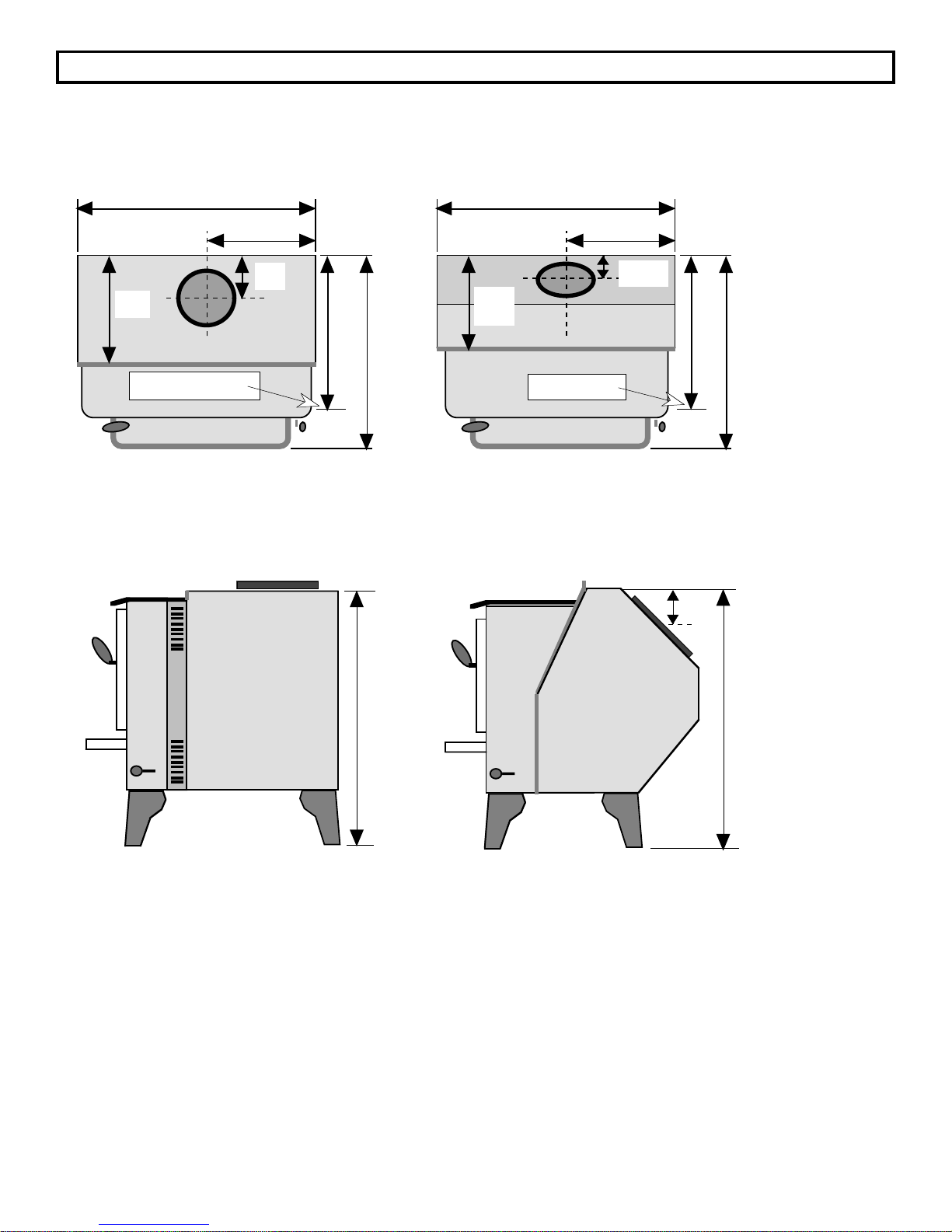
Height from floor to top of stove on:
No Legs ...................................................................................... 21 1/8" 21"
Steel Legs.................................................................................. 27 5/8" 27 1/2"
Brass Legs ................................................................................. 29" 28 7/8"
Cast Legs ................................................................................... 29" 28 7/8"
Pedestal...................................................................................... 32 5/8" 32 1/2"
996
Flush Top
Flue
Extended
45
996
o
Flue
Overall Width ................................................................................... 25 5/8" 25 5/8"
Overall Depth (Including Ashlip).................................................. 24 1/8" 24 1/8"
Weight............................................................................................... 325 lbs. (On Pedestal)
Fuel.................................................................................................... Solid Wood Only
Emissions, Efficiency, Heating Capacity and Burn Times may vary depending on actual
home floor plan, type of fuel used, and moisture content of wood. Emissions and
efficiency numbers are those that have been certified by the U.S. E.P.A. and the Oregon
Department of Environmental Quality.
Page 4
Page 5
CHIMNEY INFORMATION & REGULATIONS
Whether you install your wood heating appliance with a factory-built chimney or masonry chimney, there
are certain rules that must be followed. The following guidelines for chimney installation are included in
this manual to augment the information supplied with either the manufacturer's information for factory-built
chimneys or to insure that your present masonry chimney is suitable for this wood heating appliance. Do
not use makeshift methods or compromise in installation of any chimney equipment.
The 3-Foot, 2-Foot, 10-Foot Rule
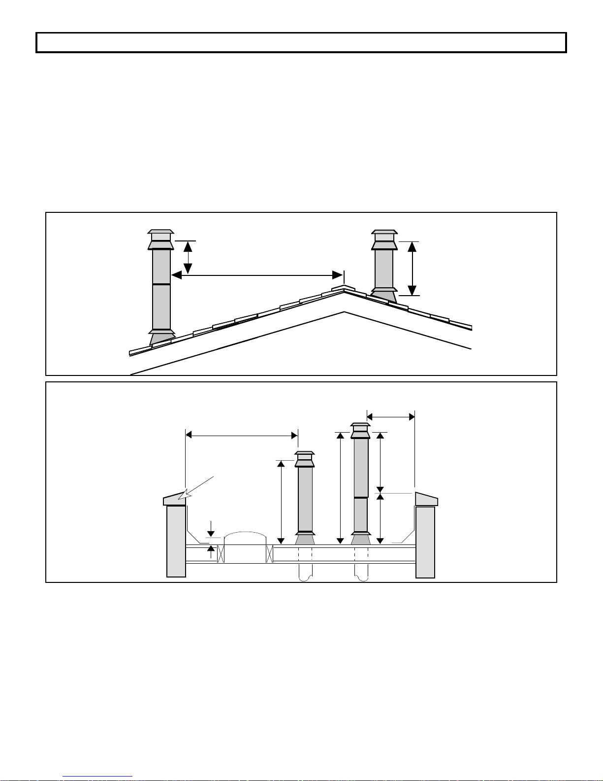
The 3-foot, 2-foot, 10-foot rule states that all chimneys (factory-built or masonry) must be:
1. At least 3 feet higher than the highest part of the roof opening through which it passes;
2. And at least 2 feet higher than any part of the roof within 10 feet, measured horizontally. A chimney
must meet requirement #1 and requirement #2. This rule, required by all building codes, applies to
both factory-built and masonry chimneys.
Minimum Chimney Height on a Sloped Roof
2' Minimum
Minimum Chimney Height on a Flat Roof
10' or Greater
Wall or
Parapet
6"
10'
Ridge
3' Minimum
Less
Than 10'
24"
42"
36"
18"
These minimum chimney heights are required by building codes for safety purposes, to allow time for
sparks exiting a chimney to cool before they land on the roof. In some problematic situations, additional
chimney height above the specified minimums may be necessary to reduce wind-induced down drafting
and back puffing, or to increase draft, thereby improving appliance operating characteristics.
"A" "B"
Page 5
Page 6
CHIMNEY INFORMATION & REGULATIONS (Cont.)
Factory-Built Chimneys
Depending on the manufacturer and where the chimney is to be installed, special supports, roof
assemblies, radiation shields, or locking bands may be supplied as a part of the chimney system. The
manufacturer's installation instructions, which are reviewed by the listing agency, specifies when and
where each of these components must be used.
There are three standard installations with factory-built chimneys. Each type of installation should use
flashing and an adjustable storm collar at the roof line to prevent water from entering the house.
Manufacturers require that chimneys extending beyond a certain height above the roof (frequently above
5 feet) must also be braced.
A chimney cap keeps out rain, birds and other animals, and may reduce down drafts. Spark arresters,
wire mesh devices designed to catch sparks and burning particles emitted with the smoke, may be
included with factory-built chimney caps. These spark arresters may become encrusted with creosote,
blocking the proper flow of flue gases out of the chimney. When burning wood, it is recommended that the
spark arrester be cleaned regularly, or removed entirely unless individual conditions or local codes
require their use.
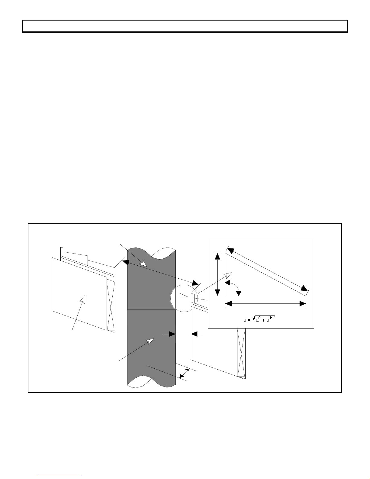
Determining the Distance Between the Chimney and Combustibles
The chimney must be kept a minimum distance of 2" away from combustibles (e.g., drywall, wood framing,
etc.). The distance between the outside surface of a chimney and combustibles is measured horizontally,
at right angles to the chimney. The pitch of the platform (e.g., the roof) must be considered in calculating
the size of the hole that is cut.
Calculating the Cut-Out on a Slanted Roof
Length of Cut-Out in Roof
Combustible Roof
Factory-Built Chimney with
Required 2" Clearance
a
2" Min.
Width of
Cut-Out in Roof
c
90û
b
Length of Cut-Out in Roof
= "c" times 2 + chimney width
Width of Cut-Out in roof
= 4" + chimney width
Page 6
Page 7

CHIMNEY INFORMATION & REGULATIONS (Cont.)
Determining the Distance Between the Chimney and Combustibles (Continued)
Installers may find it convenient to create hole cut-out templates for pitches common to their area rather
than performing the calculations or using a trial "cut and measure" system for each installation.
Carefully read the specifications, as minimum clearances other than 2 inches are sometimes required by
the manufacturer. Maintain a minimum clearance of 2" or what the manufacturer requires, whichever is
greater.
Masonry Chimneys
If you are going to use an existing masonry chimney for your wood heating appliance make sure the
chimney is inspected and found in good and safe condition. If the existing chimney is not in good
condition repairs should be made before installation.
WARNING:
Do not connect this unit to a chimney flue serving another appliance.
Do not use makeshift compromises in the installation.
Page 7
Page 8

FREESTANDING OPTIONAL EQUIPMENT
Your Avalon 996 appliance comes completely assembled. The options available for the freestanding
method of installation are listed below and require assembly.
1. Pedestal (With Solid Oak Trim)
2. Leg Kit, Steel
3. Leg Kit, Brass
4. Leg Kit, Cast
5. Avalon Blower, Rear (For Use With Pedestal Only)
6. Universal Blower, Rear (For 996 Flush Top Flue Only)
7. Blower, Front
8. Outside Air Kit (For Use With Pedestal Only)
9. Outside Air Boot (For Use With Legs Only)
1. Pedestal Assembly:
Optional Air Intake Port
Open the box marked Pedestal and
remove the pedestal and the two
attachment bolts and washers (3/8"
diameter - 16 x 3/4" hex. head
bolts).
Lift the stove onto the pedestal. Line up the threaded bolt holes in the bottom of the stove with the two
holes in the mounting angle of the pedestal. Using an open-end or socket wrench, fasten the pedestal to
the stove with the supplied bolts and washers. The Solid Oak Trim attaches to the front and rear edge of
the baseplate of the pedestal in the groove cut into the trim and is held in place by the weight of the stove.
To attach the trim, lift up the front side of the pedestal 2" (with stove attached) and slide the trim onto the
front edge, making sure it is aligned. Carefully lower the pedestal, making sure to keep the trim in place.
Repeat the process for the rear trim.
2. Steel Leg Kit Assembly:
Open the box marked Steel Leg Kit and remove the four 6 1/2" high black steel legs, complete with
rubber-tipped leveling bolts, the four attachment bolts (3/8" diameter - 16 x 3/4" hex. head bolts) and the
washers.
Raise the stove on some pieces of lumber to a height of about 7".
Line up the hole in the top of the leg with the threaded bolt hole
in each corner of the stove bottom. Using a 9/16" open end or
socket wrench, fasten the leg to the stove with the supplied
Attach Bolt (with
washer) to Stove
From Below
attachment bolts and washers, making sure the legs are flush
with the corners of the stove.
To level the stove, first make sure the leveling bolts with the rubber ends (some models come with steel
bolts -- the same directions apply) are screwed into position and backed off just enough to penetrate
below the steel portion of the leg. Unscrew each leveling bolt just enough so each leveling bolt is an
equal distance from the floor. You may wish to use a piece of wood or other spacer to measure this
distance. Next, lower the stove onto the ground and check for a level position. If slight adjustments need
to be made, make sure to first raise the stove before turning the leveling bolts. The rubber tips of the
leveling bolts will tear if they are adjusted while weight is applied to them.
Page 8
Page 9

FREESTANDING OPTIONAL EQUIPMENT (Continued)
3. & 4. Brass and Cast Legs Assembly:
Open the box marked Brass (or Cast) Leg Kit and remove the four 7 7/8" high legs, complete with rubbertipped leveling bolts, the four attachment bolts (3/8" diameter - 16 x 3/4" hex. head bolts) and the washers.
Use the same directions listed above for the steel legs assembly. The one difference is that the brass (or
cast) legs are taller, and the stove should be lifted approximately 8 1/2" above the floor before attachment.
Attach Bolt (with
washer) to Stove
From Below
5. Avalon Blower, Rear (For Use With Pedestal Only)
The Avalon rear blower is designed to improve the natural convection of this stove by pushing air through
the convection chamber of the stove and causing the heated air to exit through the vent along the top of
the stove. Follow the directions below to attach the blower.
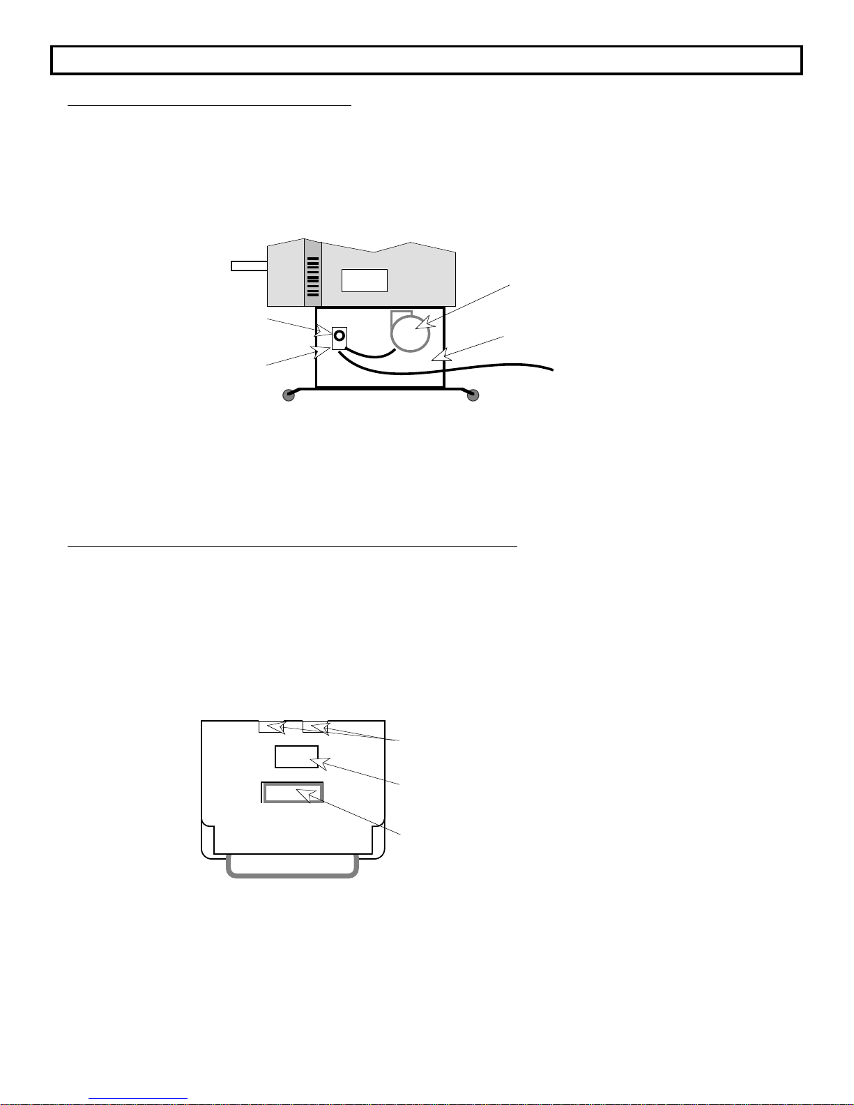
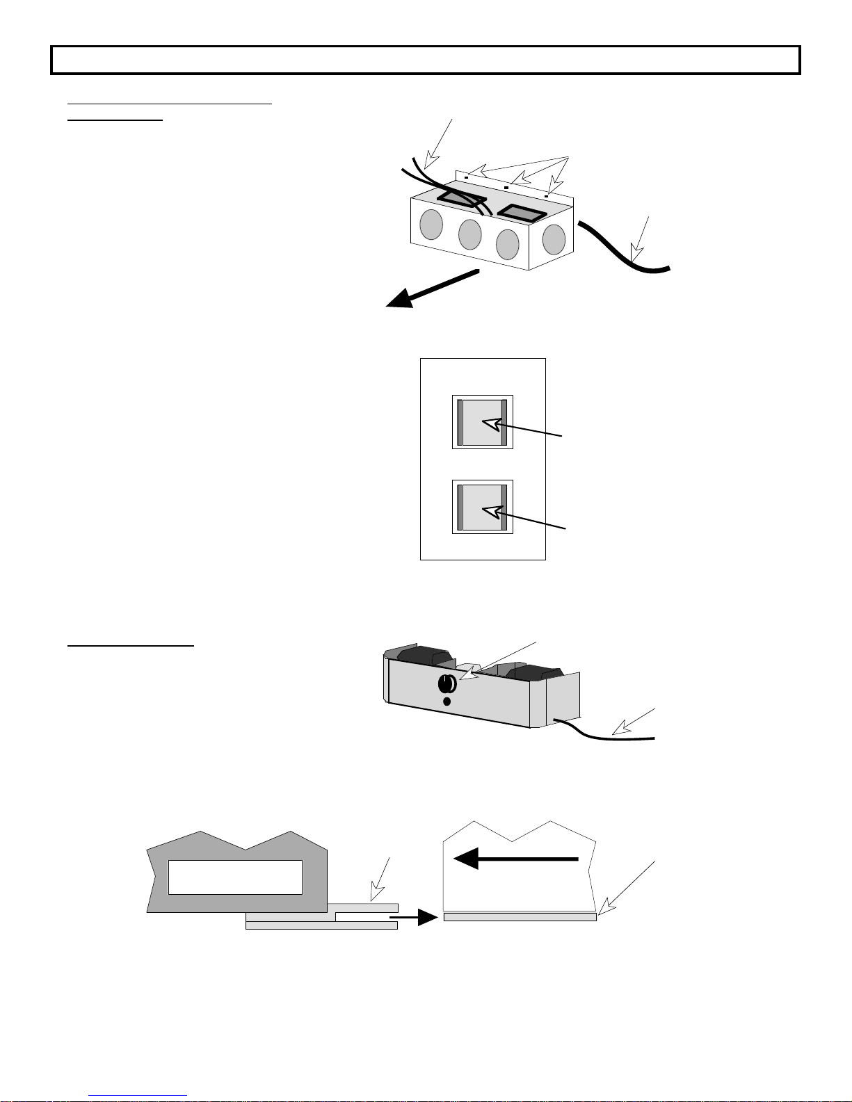
1. The stove should be attached to the pedestal. Before installing the blower, first remove the 6" x 4"
knock-out on the bottom rear of the stove by prying it out with a screwdriver (this is the opening to the
convection chamber).
Do not remove. These knock-outs
are for the universal rear blower.
Remove this knock-out for the
Avalon rear blower.
Do not remove. The front knock-out
is for the outside air connection.
2. Place the right side of the blower bracket up inside the knock-out first. Move the blower to the right
until the left side bracket can be inserted.
3. Center the blower evenly in the knock-out. Attach the two screws provided with the blower to the
blower through the notches in the knock-out. This will hold the blower against the stove.
Rear
Cut-Away
V i e w
Bottom panel of
the stove body
Notch in
knock-out
Blower Housing
Stove
Attach the two
screws through
the notches
and into the
blower housing
Page 9
Page 10
FREESTANDING OPTIONAL EQUIPMENT (Continued)
5. Avalon Blower, Rear (Continued)
4. The blower has a control box which needs to be attached to the pedestal body. With the stove
attached to the pedestal, locate the hole on the right side of the pedestal. Remove the knob on the
control box and the nut that is on the threaded shaft located directly behind where the knob was.
Feed the control box and wiring into the pedestal until the threaded shaft is directly behind the hole in
the pedestal. Insert the threaded shaft through the hole from the back and re-attach the nut until the
control box is secure against the pedestal. Re-attach the knob.
Stove
Hole in pedestal
Control Box
Blower Housing
Pedestal (Shown Transparent)
To Power Supply
5. Plug in the blower and test its operation. It should blow air out of the vent on top of the stove. The
blower is turned off by turning it all the way counter-clockwise. Turning the knob clockwise will
decrease the speed of the blower.
6. Universal Blower, Rear (For 996 Flush Top Flue Only)
The universal rear blower is designed to improve the natural convection of the stove by pushing air
through the convection chamber of the stove and causing the heated air to exit through the vents along
the top of the stove. The blower mounts to the back of the stove centered on the lower edge with three
screws. It also has a thermodisk assembly which turns the blower on and off automatically. Follow the
directions below to attach the blower.
1. Before installing the blower, first remove the two knock-outs on the bottom rear edge of the stove by
prying them out with a screwdriver. They are approximately 1" by 6" and are located near the rear
edge of the stove.
Remove these knock-outs for the
universal rear blower.
Do not remove. This knock-out is on
some models for the Avalon rear blower.
Do not remove. The front knock-out
is for the outside air connection.
Page 10
Page 11
FREESTANDING OPTIONAL EQUIPMENT (Continued)
6. Universal Blower, Rear (Continued)
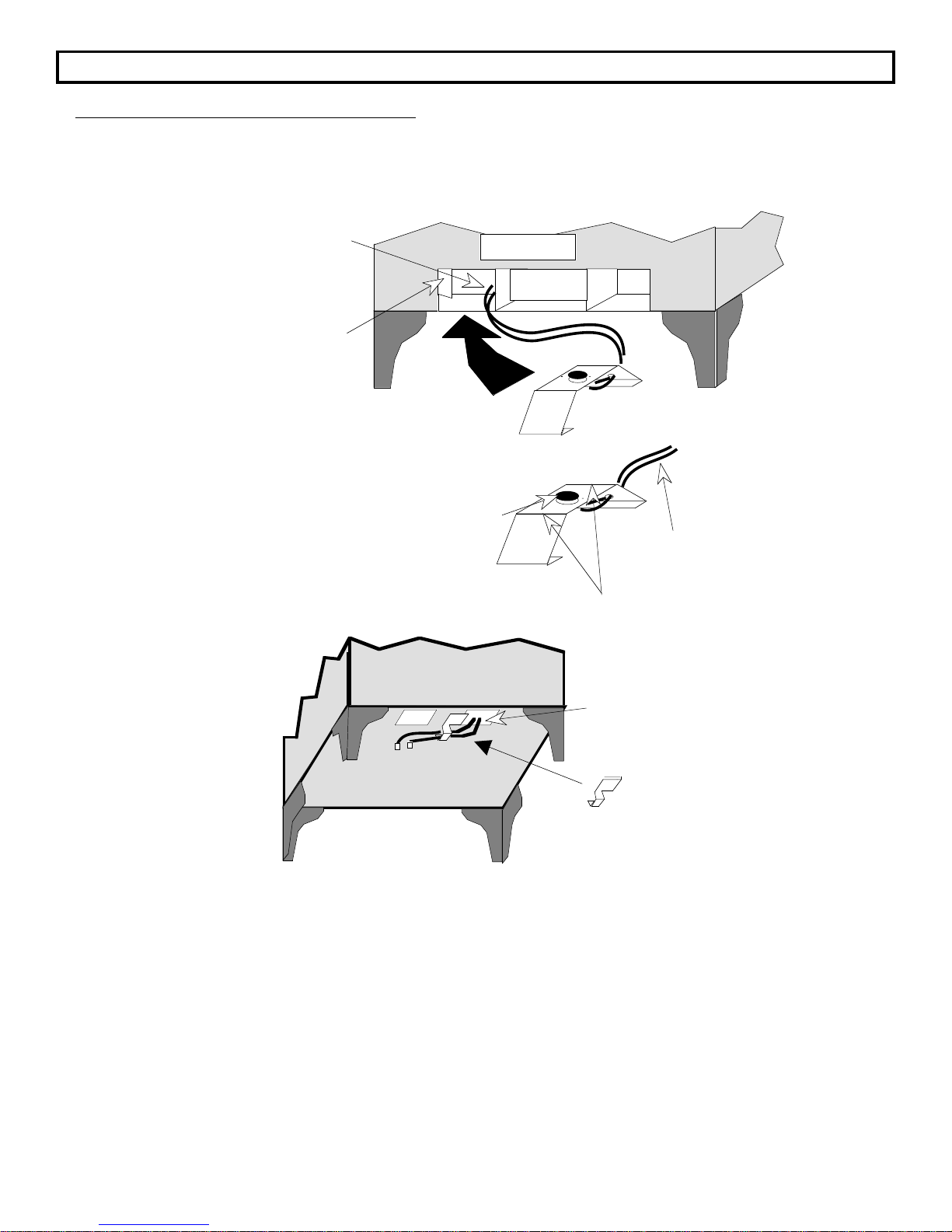
2. Feed the two wires coming from the thermodisk assembly through the stove and out the left side
knock-out that was removed in step 1. Take the thermodisk assembly and insert it directly below the
ashlip into the left side of the air intake. The thermodisk assembly should be positioned just behind
the support tab that sits at an angle to the left front corner.
Feed wires through stove and
out the left knock-out
removed in step 1.
Support Tab
Front of Stove
Thermodisk
The thermodisk must come in contact
with the bottom of the firebox when it is
As s emb ly
Thermodisk
installed. To insure this, bend the metal
portion of the thermodisk assembly up or
down to create a snug fit.
Bend metal up or down here to create a snug fit
Wires that
attach to
blower box
Slide the wire clip
over the edge of the
strip of metal
between the two
knock-outs removed
Feed the two thermodisk
wires into the eye of the
wire clip.
in step 1. Insert the
two thermodisk wires
into the eye of the
wire clip and pull the
slack wire out of the
stove.
Slide the wire clip over the
edge of the strip of metal
between the two knock-outs.
NOTE: The wires coming from the thermodisk assembly must not have too much slack
Ð these wires pass near the firebox and can cause a short if the slack is not
taken in and held in place with the wire clip. Do not pull so hard on the wires
that you dislodge the thermodisk housing from its location.
There are two yellow wires coming out of the blower box. These two wires must exit the blower box
from the top, not through the small access hole in the back. Re-route these wires so they exit out of
the top of the blower box. Attach these two wires to the two wires coming from the thermodisk by
connecting the mating quick-connects. It does not matter which wire from the blower box connects to
which wire from the thermodisk assembly. Push all of the excess wire into the cavity inside the blower
box.
Page 11
Page 12
FREESTANDING OPTIONAL EQUIPMENT (Continued)
6. Universal Blower, Rear
(Continued)
The two yellow wires
attach to the thermodisk.
3. Place the blower box near the bottom
rear of the stove and push any slack
wire into the blower box so that when
the blower box is attached the excess
wire will not contact the stove.
4. Attach the blower box to the bottom
rear of the stove with the three screws
provided. Push the blower box up
against the stove while tightening the
screws.
UNIVERSAL REAR BLOWER OPERATION
The blower controls are located on the switch box
that is connected by a cord to the blower. There
are two rocker switches that determine the speed
and mode (automatic or manual) of the blower.
The two speeds are RUN (slower) and STARTUP
(faster). The two modes are AUTO (the
thermodisk controls the switch and the
temperature of the firebox will determine when the
blower starts or stops) and MAN (manual Ð the
blower will run on the speed setting selected).
The blower should be switched "OFF" for
approximately 30 minutes after each reload of the
stove. This is to allow the stove to reach
operating temperature.
Three holes for attaching the blower
box to the back of the stove
FRONT
RUN OFF STARTUP
AUTO OFF MAN
Power Cord
(exits from back
of blower box)
Speed Control Rocker Switch
(If OFF is selected, the blower
will always be off, even if on
automatic)
Mode Rocker Switch (If OFF
is selected, the blower will
always be off, no matter what
the speed setting is at)
7. Blower, Front
Blower Control Knob
The front blower is designed to improve your
appliance's natural convection by pushing
heated air through the convection chamber
Power
Cord
and out of the vents along the top.
1. Carefully slide the blower assembly underneath the ashlip so that the two clips on the lower back
edge of the blower assembly slide over the front edge of the sheet metal under the appliance. You
should be able to feel the blower assembly snap into place as you slide it in. This is all the assembly
needed to attach the blower assembly.
Rear of Blower
Assembly (Side View)
Clip (One on
each side)
FRONT OF STOVE
Avalon Stove
or Insert
Sheet Metal
Below Ashlip
2. Plug in the blower and test its operation. It should blow air out of the vents on top of the appliance.
The blower is turned off by turning it all the way counter-clockwise. Each click clockwise will increase
the speed of the blower.
Page 12
Page 13
FREESTANDING OPTIONAL EQUIPMENT (Continued)
8 & 9. Outside Air Kit (Pedestal Only) and Outside Air Boot (Legs Only)
The outside air kit and boot are options that allow the stove to use outside air for combustion instead of
room air. This is a requirement for mobile home installations. Both the outside air kit and boot work in the
same fashion. Instead of having the air enter through the combustion air intake under the ashlip, the
outside air kit and boot re-route the air intake so the air is drawn from outside. This section will address
the special installation factors that must be considered when installing this model of stove with an outside
air kit or boot.
THE SPECIFIC INSTRUCTIONS FOR INSTALLING THE OUTSIDE AIR KIT AND OUTSIDE
AIR BOOT ARE INCLUDED WITH THOSE KITS AND MUST BE READ PRIOR TO
INSTALLING THE STOVE.
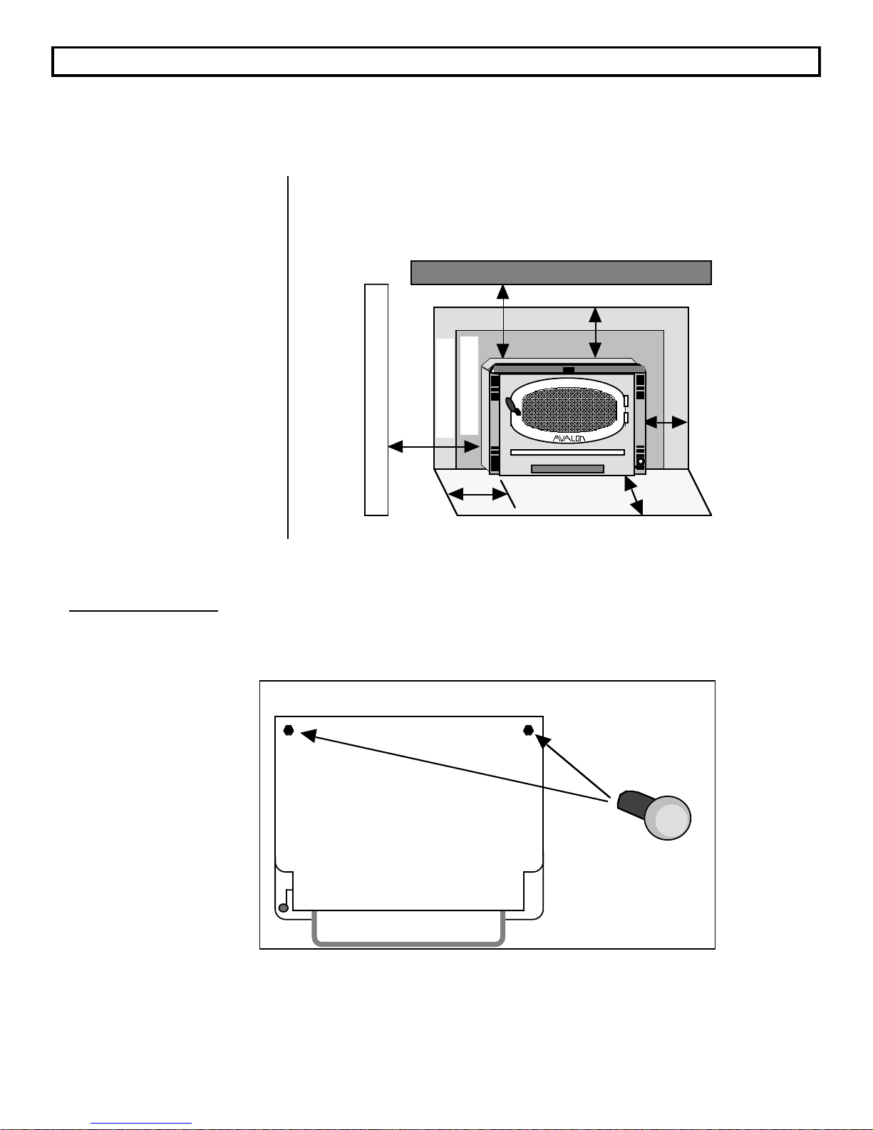
The most important factor that must be
considered when installing an outside air kit
or boot with your stove is placement. Make
detailed plans to determine the precise
location for your stove. When installing the
outside air kit or boot there are two
placement considerations that must be
addressed simultaneously. They are:
1. Does the stove line up with the flue in the
right location, avoiding structural
members of the roof?
Stove placement
should be made
so the chimney
avoids interference
with structural
members in roof.
2. Does the hole that is cut in the floor and
hearth for the outside air kit or boot avoid
all structural members of the floor?
These two questions must be considered in
determining the final location for the stove.
To determine the size, shape, and location of
the hole in the hearth and floor, refer to the
directions included with the outside air kit
and boot. To determine the size and location
of the hole in the roof, refer to the directions
included with the chimney being used and
the location of the flue collar in the section
"FREESTANDING INSTALLATION SPECIFICATIONS"
See the illustration to the right.
Do not remove any
of these knock-outs
Pedestal
Location
Knock-Out For Outside Air
Kit or Outside Air Boot
Stove placement
should be made
so the hole cut in
the floor and
hearth avoids
interference with
structural
members in floor.
Outside
Air Kit
After the precise location of the stove is
determined, the outside air kit or boot should
be installed prior to installing the stove.
Follow the directions included with the
outside air kit or boot. Make sure to remove
the correct knock-out for the outside air kit or
boot. See the illustration to the left.
Page 13
Page 14
PREPARATION FOR INSTALLATION - FREESTANDING
READ THIS ENTIRE MANUAL BEFORE YOU INSTALL AND USE YOUR NEW APPLIANCE. FAILURE TO
FOLLOW INSTRUCTIONS MAY RESULT IN PROPERTY DAMAGE, BODILY INJURY, OR EVEN DEATH.
PREPARATION:
1. Remove all tape and packaging.
2. Remove the wood shipping frame from around and under the appliance.
3. Check that no parts have become loose and the appliance has not been damaged during shipping.
4. Remove the hardware pack from the appliance.
5. READ THE OWNER'S MANUAL BEFORE PROCEEDING.
* Appliance should be located such that no doors, drapes, furniture or other combustibles can be placed
closer or swing closer than the minimum stated clearances.
* The appliance must be installed in a level, secure position.
REQUIRED FLOOR PROTECTION:
Minimum size 37 5/8"W x 41 3/8"L of non-combustible
material with a minimum thickness of 26 gauge floor
protection must extend under the appliance.
Chimney Lengths Maximum Minimum
Vertical 33 Feet 15 Feet
If you are going to use a factory built chimney it should be 6"
in diameter and a type suitable for use with solid fuels.
Follow the manufacturer's installation instructions packaged
within the chimney appliance.
Wall, ceiling, or roof penetrations can be made only with U.L.
listed chimney components. NOTE: Your interior single wall
chimney connector or double wall chimney connector must
not pass through an attic, roof space, closet or similar
unsealed space, floor, ceiling, wall or partition of
combustible construction.
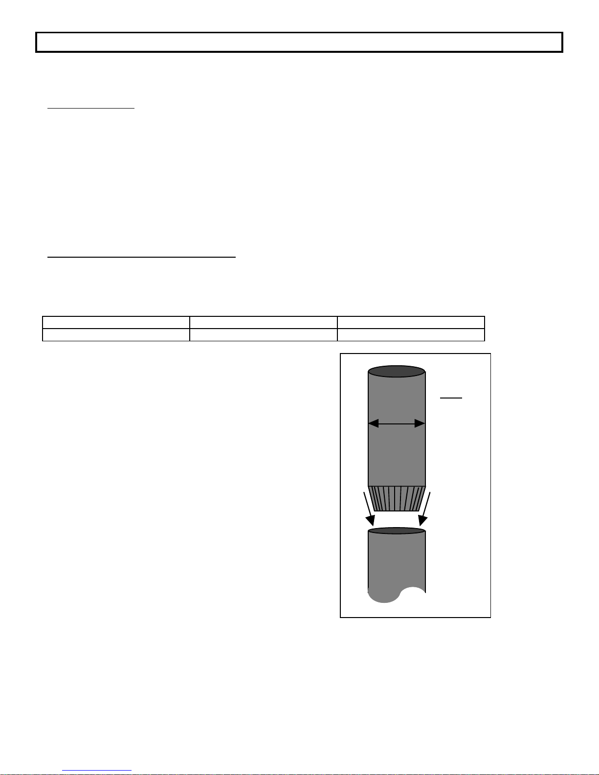
All sections of interior chimney connector should be securely
fastened together by at least three sheet metal screws. The
crimped end must be installed downwards (see drawing to
right).
When lifting the appliance, you may choose to remove the
interior components to make it lighter. Refer to the section
"REPLACEMENT PARTS AND REMOVAL INSTRUCTIONS"
for the proper sequence of removal and replacement of
internal components.
Front - 16"
Sides - 6"
Back - 6"
Top
6"
Page 14
Page 15
FREESTANDING INSTALLATION - SPECIFICATIONS
REQUIRED FLOOR PROTECTION:
}
6 "
Front = 16" NOTE: Front floor
protection is
measured from the
door opening.
Sides = 6"
Back = 6"
CLEARANCE TO COMBUSTIBLES:
Single Wall Connector
Backwall
A. Sidewall to unit.........................
D
A
Sidewall
E
B
B. Backwall to unit.........................
C. Cornerwall to unit .....................
D. Connector to sidewall..............
E. Connector to backwall .............
F. Connector to cornerwall..........
Reduced Clearance *
A. Sidewall to unit .........................
B. Backwall to unit .........................
C. Cornerwall to unit .....................
D. Connector to sidewall..............
E. Connector to backwall .............
F. Connector to cornerwall..........
}
6 "
16" From Door Opening
996
Flush
Top Flue
Extended
45
14"
14 1/2"
11"
23 1/2"
15 1/2"
19 1/2"
14"
9 1/2"
7 1/2"
23"
10"
15 1/2"
996
o
Flue
14"
17 1/2"
11"
23 1/2"
15 1/2"
16 1/2"
16"
14"
7 1/2"
25"
10"
12"
Cornerwall
C
F
F
Cornerwall
C
* Components required for alcove, mobile home,
and reduced clearance installations are one of
the following listed double wall connectors and
chimney systems.
¥ DURAVENT model DVL with DURA-PLUS chimney
¥ AMERI-TEC model DCC with model HS chimney
¥ SECURITY model DP with SECURITY model ASHT or S2100
chimney
¥ METAL-FAB model DW with model TG chimney
¥ SELKIRK METALBESTOS model DS connector with model SSII
chimney
¥ OLIVER MACLEOD PROVENT model PV connector with model
3103 chimney
¥ GSW-JAKES EVENS SUPERPIPE 2100
¥ Standard Masonry Chimney with any one of the
above listed connectors
Page 15
Page 16
FREESTANDING INSTALLATION - SPECIFICATIONS (Cont.)
TOP VIEW
996 Flush Top Flue 996 Extended 45o Flue
25 5/8"
15"
Firebox Front
SIDE VIEW
996 Flush Top Flue 996 Extended 45o Flue
12 13/16"
4"
19
3/8"
24
1/8"
10
3/8"
25 5/8"
12 13/16"
3 5/8"
19
3/8"
24
1/8"
Firebox Front
2 7/8"
Overall Height With:
Steel Legs............................................... 27 5/8" 27 1/2"
Brass Legs .............................................. 29" 28 7/8"
Cast Legs ................................................ 29" 28 7/8"
Pedestal................................................... 32 5/8" 32 1/2"
See
Chart
Below
996 Flush Top
Flue
996 Extended 45
Flue
See
Chart
Below
o
Page 16
Page 17

FREESTANDING INSTALLATION
Standard Ceiling Installation
When installing a freestanding stove into a residence with a standard ceiling, certain precautions should
be taken to insure a safe installation. The directions below illustrate one way to install your freestanding
stove into a standard ceiling with a factory-built chimney. There are several other alternative methods.
Check with your dealer or installer for information on other options available to you.
IT IS RECOMMENDED THAT NO CEILING
SUPPORT MEMBER BE CUT FOR CHIMNEY
AND SUPPORT BOX INSTALLATION. IF IT IS
NECESSARY TO CUT THEM, THE MEMBERS
MUST BE MADE STRUCTURALLY SOUND.
1. Make sure the factory built chimney satisfies
all of the rules in the section titled
"CHIMNEY INFORMATION &
REGULATIONS".
2. Follow all of the regulations and guidelines
specified in the sections titled
"FREESTANDING INSTALLATION SPECIFICATIONS" and "PREPARATION
FOR INSTALLATION - FREESTANDING".
3. Carefully place the stove on top of the floor
protection and join the chimney connector to
the stove. When determining the placement
of the stove, make sure to take into
consideration the necessary clearances to
combustibles and the placement of the
chimney.
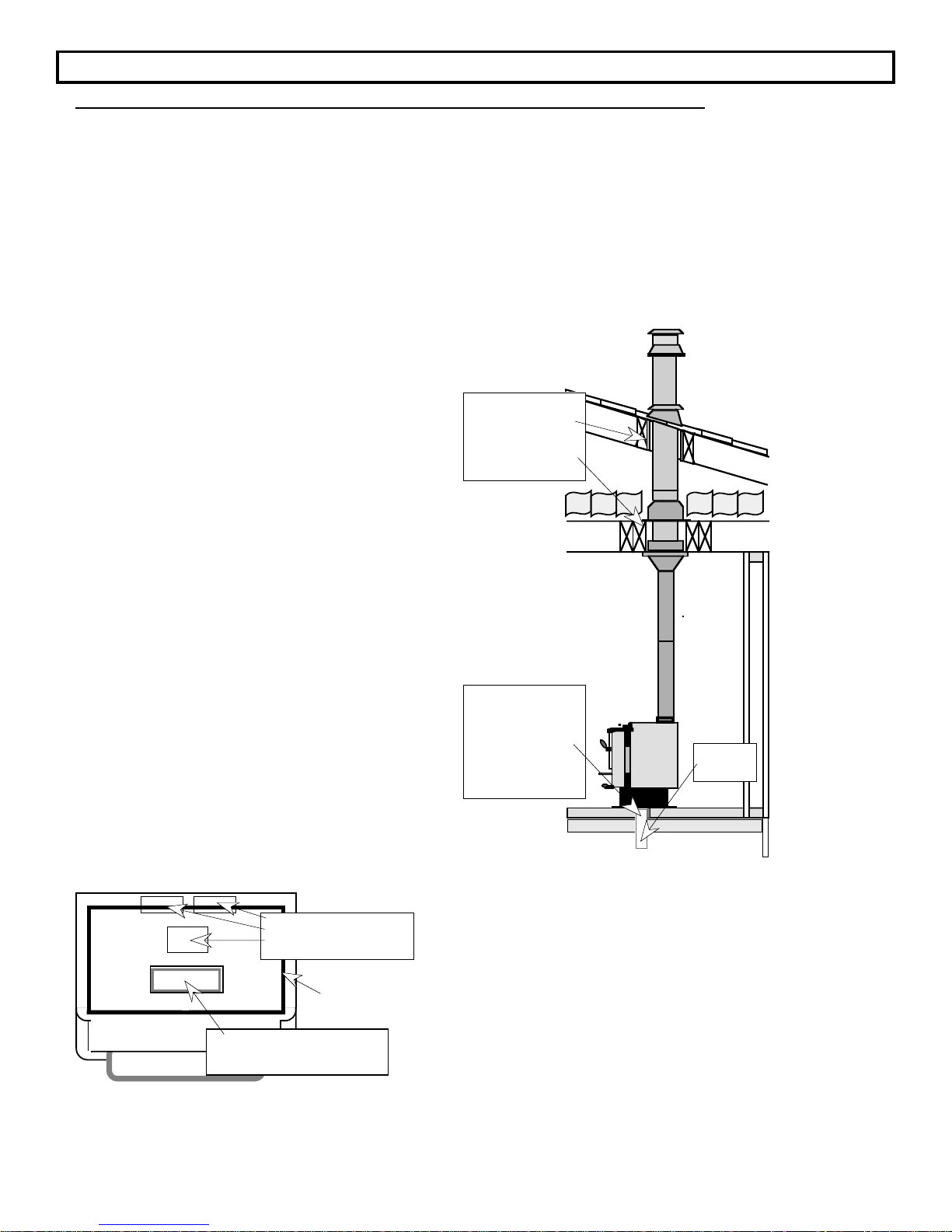
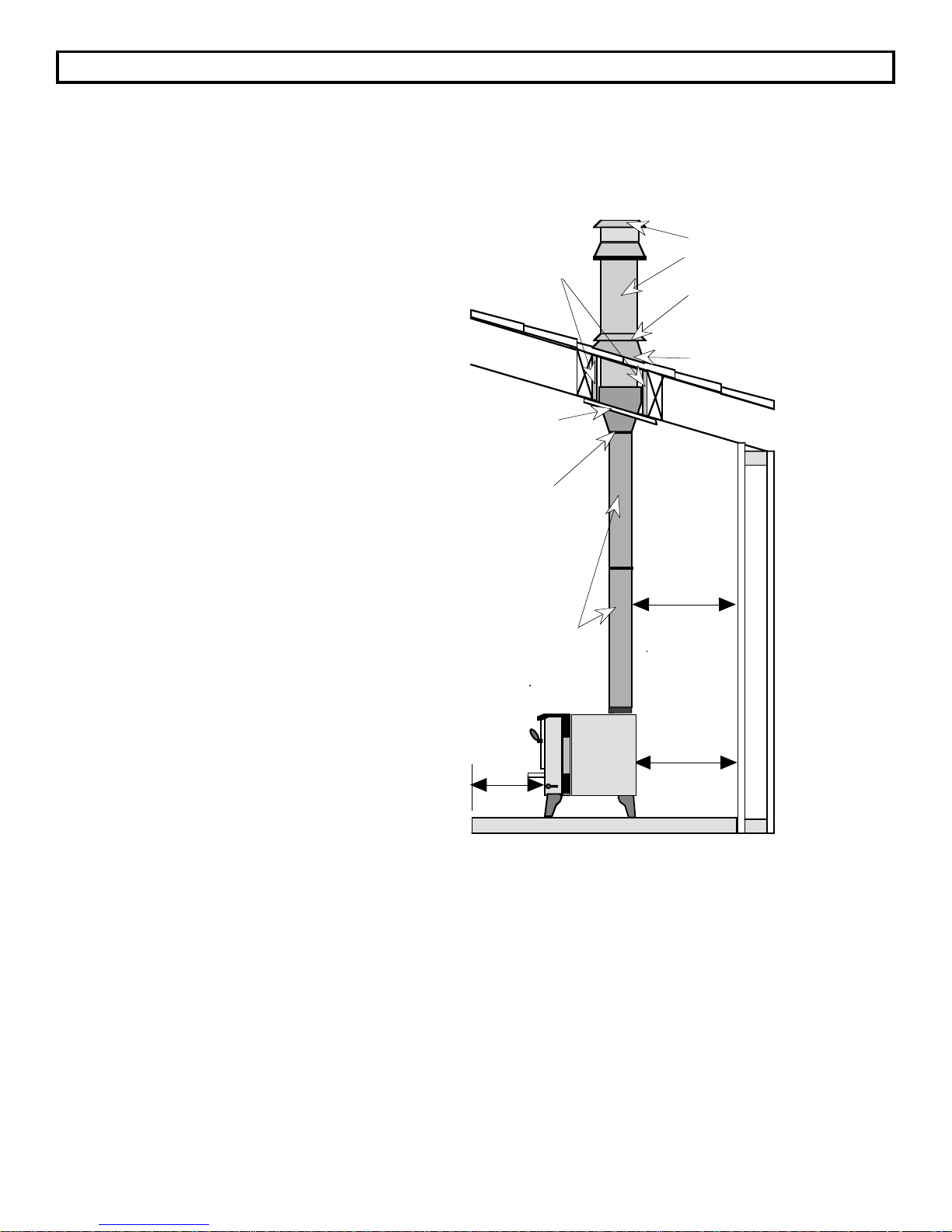
NOTE: When the chimney connector extends to a
standard ceiling, as shown to the right, a support
package and sometimes a chimney connector
adapter are installed at the ceiling.
Chimney Sections
Roof Radiation Shield
(Required by some
manufacturers)
Attic Radiation Shield
Minimum Air Space
in Accordance with
Chimney Listing
Chimney Cap
Storm Collar
Roof Flashing
Insulation
Min. 15 1/2" for
Single Wall, 10"
for Reduced
Clearance
Connector
Working from the attic or roof, sufficient sections of
factory-built chimney (available in different
Chimney Connector
lengths) are installed to go through the space
above the ceiling, then through and above the
roof to the correct height above the roof line. The
chimney sections should be stacked and locked
securely as specified by the manufacturer.
A
minimum clearance of 2 inches is typically
required between the outside surface of the
factory-built chimney and any combustibles or
996 Flush Top Flue
Shown Here Ð Follow the
clearances for the 996
Extended 45 Flue when
that model is used.
Min.
16"
Min. 14 1/2" for
Single Wall, 9
1/2" for Reduced
Clearance
Connector
insulation; the air space around the chimney
never must be filled with insulation or any other
material.
IMPORTANT: Make sure to follow all guidelines provided by the manufacturer of the chimney for safety
in installation.
Page 17
Page 18
FREESTANDING INSTALLATION (Cont.)
Cathedral Ceiling Installation
When installing a freestanding stove into a residence with a cathedral ceiling, certain precautions should
be taken to insure a safe installation. The directions below illustrate one way to install your freestanding
stove into a cathedral ceiling with a factory-built chimney. There are several other alternative methods.
Check with your dealer or installer for information on other options available to you.
IT IS RECOMMENDED THAT NO CEILING
SUPPORT MEMBER BE CUT FOR CHIMNEY
AND SUPPORT BOX INSTALLATION. IF IT IS
NECESSARY TO CUT THEM, THE MEMBERS
MUST BE MADE STRUCTURALLY SOUND.
1. Make sure the factory-built chimney
satisfies all of the rules in the section titled
"CHIMNEY INFORMATION &
REGULATIONS".
2. Follow all of the regulations and guidelines
specified in the sections titled
"FREESTANDING INSTALLATION SPECIFICATIONS" and "PREPARATION
FOR INSTALLATION - FREESTANDING".
3. Carefully place the stove on top of the floor
protection and join the chimney connector
to the stove. When determining the
placement of the stove, make sure to take
into consideration the necessary
clearances to combustibles and the
placement of the chimney.
NOTE: In rooms with cathedral
ceilings, the roof and ceiling are
combined . For this type of installation,
manufacturers of factory-built chimneys
provide a special cathedral ceiling roof
support kit with instructions that should
be followed.
Roof Radiation Shield
(Required by some
manufacturers)
Cathedral-Style
Chimney
Support
Finishing Collar
Minimum Air Space
in Accordance with
Chimney Listing
Chimney Connector
996 Flush Top Flue
Shown Here Ð Follow the
clearances for the 996
Extended 45 Flue when
that model is used.
Min.
16"
Chimney Cap
Factory-Built
Chimney
Storm Collar
Roof Flashing
Min. 15 1/2" for
Single Wall, 10"
for Reduced
Clearance
Connector
Min. 14 1/2" for
Single Wall, 9
1/2" for Reduced
Clearance
Connector
IMPORTANT: Because of the slope of the cathedral ceiling, care should be taken to extend the chimney
sufficiently far into the room so that the chimney connector will meet the minimum clearances requirement
from the sloped combustible ceiling. The greater the pitch of the ceiling, the further into the room the
chimney section must extend. Use the concepts from "CHIMNEY INFORMATION & REGULATIONS" to
accurately measure the appropriate distance from a sloping ceiling.
Page 18
Page 19
FREESTANDING INSTALLATION (Cont.)
Horizontal Installation Into Factory-Built Chimney
When installing a freestanding stove into a residence with horizontal connection to a factory-built
chimney, certain precautions should be taken to insure a safe installation. The directions below illustrate
one way to install your freestanding stove with a horizontal installation into a factory-built chimney. This
requires the use of an insulated tee, a wall support, wall closure plate, wall bands, roof flashing, storm
collar and chimney cap. There are several other alternative methods. Check with your dealer or installer
for information on other options available to you.
1. Make sure the factory-built
chimney satisfies all of the rules in
the section titled "CHIMNEY
INFORMATION & REGULATIONS".
2. Follow all of the regulations and
guidelines specified in the sections
titled "FREESTANDING
INSTALLATION - SPECIFICATIONS"
and "PREPARATION FOR
INSTALLATION - FREESTANDING".
3. Carefully place the stove on top of
the floor protection and join the
chimney connector to the stove.
When determining the placement
of the stove, make sure to take into
consideration the necessary
clearances to combustibles and
the placement of the chimney.
NOTE: An exterior chimney is subject to
cold outdoor temperatures, leading to
greater heat loss, creosote
accumulation, and moisture
condensation in the chimney. To reduce
this possibility, the chimney may be
enclosed in a chase. Specified
minimum clearances from combustibles
must be maintained. If the chase is
insulated, the insulated walls should be
sheathed with dry-wall or covered with
wire mesh to keep the insulation in
place. If the chase is to go through an
eaves area, a firestop must be used to
prevent air flow between the chase and
the attic. This is to isolate the chase/attic
area from fire and to prevent attic
insulation from falling into the chase
enclosure.
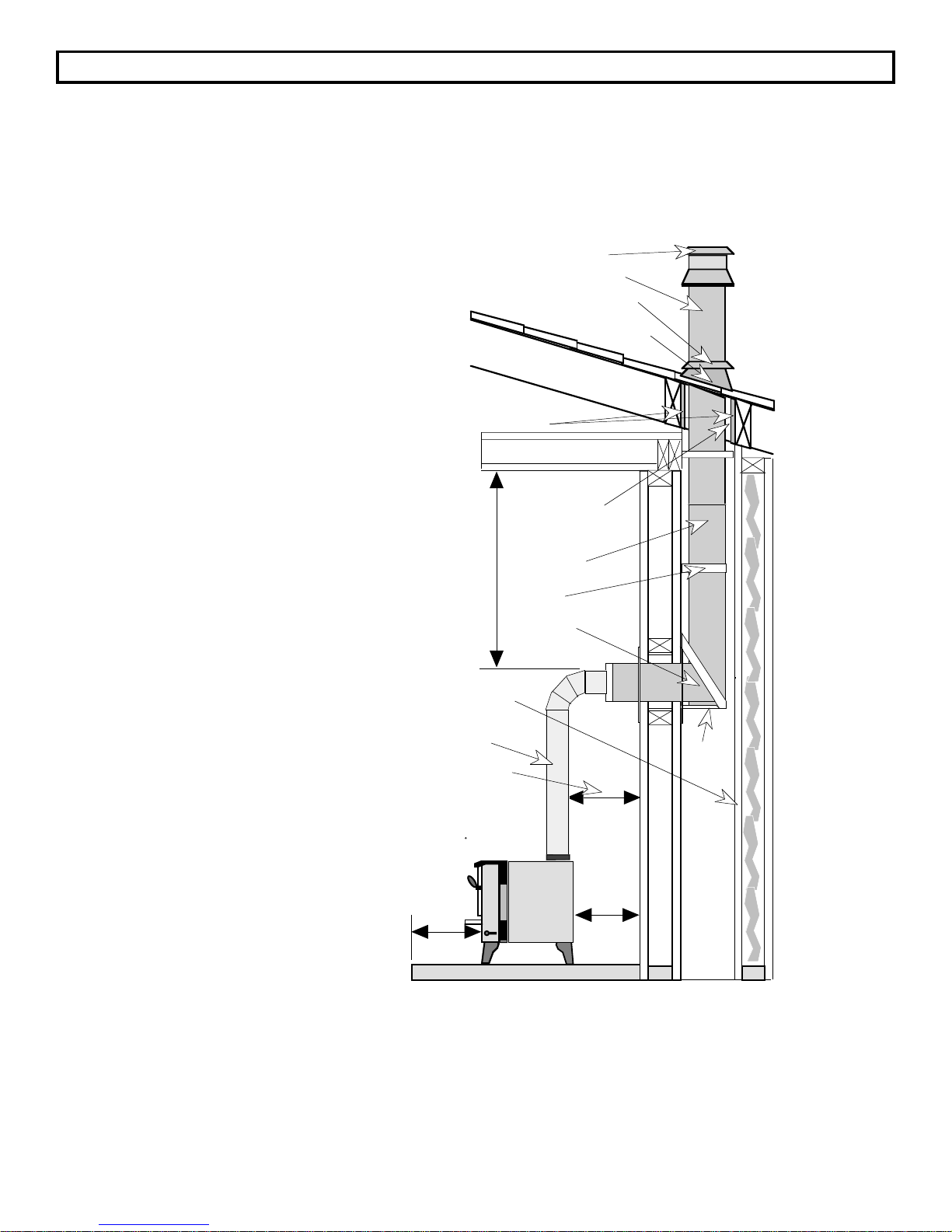
Roof Radiation Shield
(Required by some
manufacturers)
18" Min.
Chase (Optional)
Chimney Connector
Min. 15 1/2" for Single
Wall, 10" for Reduced
Clearance Connector
996 Flush Top Flue
Shown Here Ð Follow the
clearances for the 996
Extended 45 Flue when
that model is used.
Min.
16"
Chimney Cap
Chimney Sections
Storm Collar
Minimum Air Space
in Accordance with
Chimney Listing
Factory-Built
Metal
Chimney
Wall Band
Insulated Tee
Min. 14 1/2"
for Single
Wall, 9 1/2"
for Reduced
Clearance
Connector
Roof Flashing
Wall
Support
Page 19
Page 20

FREESTANDING INSTALLATION (Cont.)
Hearth Stove Installation Using a Positive Connection
When installing a freestanding stove into a masonry fireplace that is using a positive connection, certain
precautions should be taken to insure a safe installation. The advantages of this type of connection are
excellent chimney draft and ease of cleaning. A block-off plate is not needed for this type of installation
because the positive connection provides sufficient draft. If one is used, it need not be airtight. The
directions below illustrate one way to install your freestanding stove into a positive connection factory-built
chimney. There are several other alternative methods. Check with your dealer or installer for information
on other options available to you.
1. Install the positive connection (reline) through the masonry chimney according to the manufacturer's
instructions for installation and support. Make sure to follow all of the manufacturer's safety
precautions during assembly. Inspect the masonry chimney and make sure the chimney is in good
and safe condition. If the existing chimney is not in good condition, repairs should be made before
installation. Make sure the masonry fireplace and positive connection conform to all of the rules
outlined in the section titled "CHIMNEY INFORMATION & REGULATIONS".
2. If a block-off plate is desired (optional), follow the directions for making a block-off plate in the section
titled "INSTALLATION OF A FIREPLACE BLOCK-OFF PLATE".
3. Follow all of the clearance regulations for placement of your stove specified in the sections titled
"FREESTANDING INSTALLATION - SPECIFICATIONS" and "PREPARATION FOR INSTALLATION FREESTANDING ". Furthermore, make sure the stove also meets the specifications listed in the
sections titled "FIREPLACE INSERT - SPECIFICATIONS" and "PREPARATION FOR INSTALLATION MASONRY FIREPLACE INSERT" for clearance to the masonry fireplace.
4. If you are using a block-off plate, slide the pipe into the plate up through the damper. If you are not
using a block-off plate, make sure the last segment of the positive connection will reach the stove
once it is in place.
5. You may now place your stove into position so that it lines up with the chimney connector.
6. With the connector in place, you now have completed the positive connection for your insert. It is a
good idea to check your connection by trying to rock the chimney connector back and forth. If it feels
snug, a good connection is established. If you can feel some play when you rock it back in forth,
make sure that the insert is properly aligned and that the connector fits tight in the flue collar on the
top of the stove.
7. Check the diagram on the following page. Make sure all of the items listed are complete.
Follow these directions in reverse order for periodic inspection and cleaning.
WARNING: Do not connect this unit to a chimney flue serving another appliance.
Do not use makeshift compromises in the installation.
Page 20
Page 21
FREESTANDING INSTALLATION (Cont.)
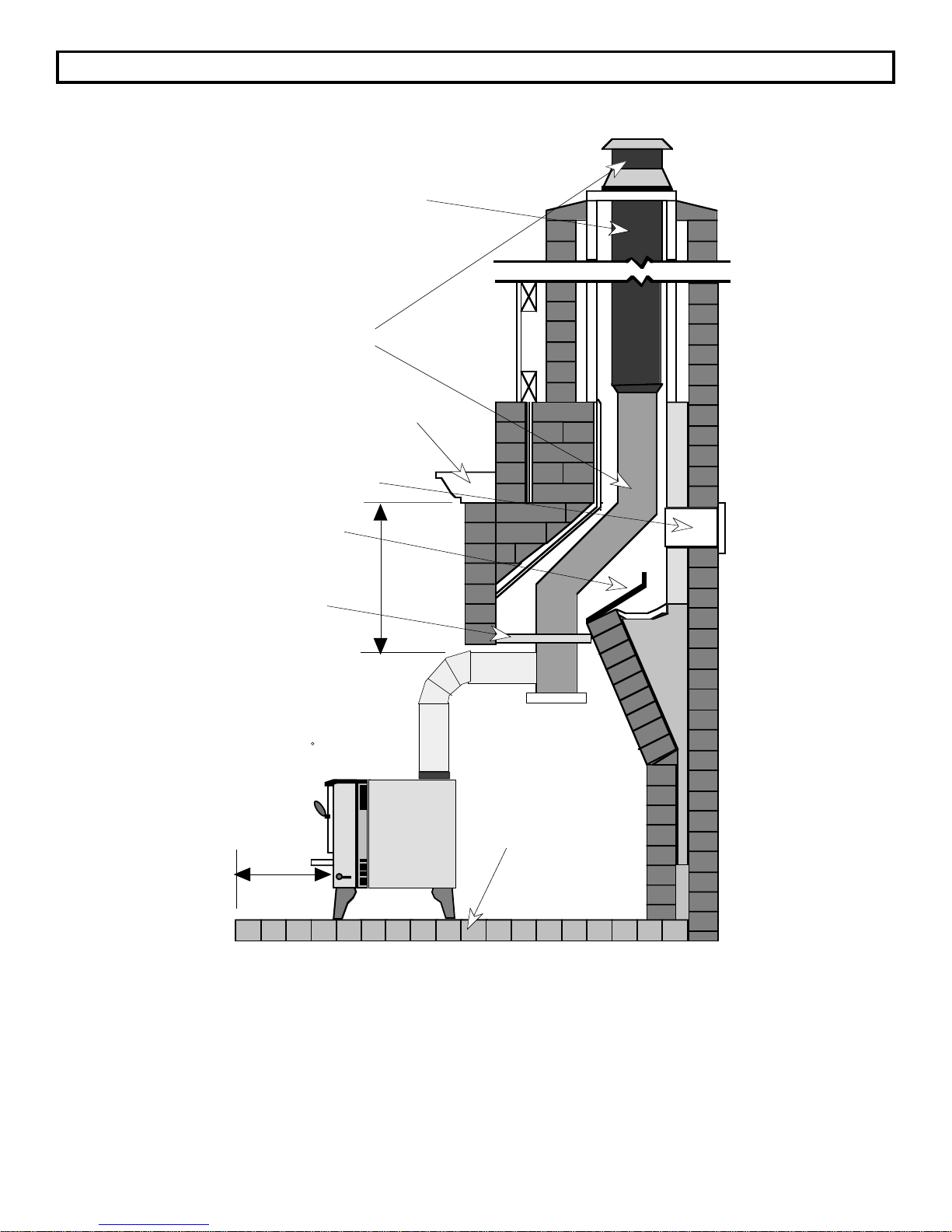
Hearth Stove with Positive Connection (Continued)
Stainless Steel
Chimney Liner System
Follow Liner
Manufacturer's
Instructions on
Installation and
Support
Combustible
Mantle
Airtight Insulated
Clean-Out
Remove Damper or
Wire it Open
Block-off Plate or
Damper Adapter
(Optional)
996 Flush Top Flue
Shown Here Ð Follow the
clearances for the 996
Extended 45 Flue when
that model is used.
Min.
16"
Min. 18"
Floor Protection
Follow the directions on the previous page for installation.
Page 21
Page 22

FREESTANDING INSTALLATION (Cont.)
Hearth Stove Installation Using a Direct Connection
Using the direct connection between your hearth stove and masonry chimney allows you to use your
existing chimney with a minimum of installation work. An airtight seal must be made with a block-off plate
to insure that your chimney will draw the smoke out of the appliance. The directions below illustrate one
way to install your freestanding stove into a direct connection. There are several other alternative
methods. Check with your dealer or installer for information on other options available to you.
1. Inspect the masonry chimney and follow all the rules outlined in the section titled "CHIMNEY
INFORMATION & REGULATIONS". Make sure the chimney is inspected and found in good and safe
condition. If the existing chimney is not in good condition, repairs should be made before installation.
2. Follow the directions for making a block-off plate in the section titled "INSTALLATION OF A
FIREPLACE BLOCK-OFF PLATE".
3. Follow all of the clearance regulations for placement of your stove specified in the sections titled
"FREESTANDING INSTALLATION - SPECIFICATIONS" and "PREPARATION FOR INSTALLATION FREESTANDING " . Furthermore, make sure the stove also meets the specifications listed in the
sections titled "FIREPLACE INSERT - SPECIFICATIONS" and "PREPARATION FOR INSTALLATION MASONRY FIREPLACE INSERT" for clearance to the masonry fireplace.
4. Once the plate is in position, slide the pipe into the plate up through the damper. It must extend up to
the flue liner or at least one foot past the block-off plate.
5. You may now position the hearth stove and connector pipe so that it can be easily joined with the pipe
coming from the flue opening.
6. With the connector in place, you have now completed the direct connection for your insert. It is a good
idea to check your connection by trying to rock the chimney connector back and forth. If it feels snug,
a good connection is established. If you can feel some play when you rock it back in forth, make sure
that the stove is properly aligned and that the connector fits tight in the flue collar on the top of the
stove.
7. Take a look at the figure on the following page. Make sure all of the items listed are complete.
Follow these directions in reverse order for periodic inspection and cleaning.
WARNING: Do not connect this unit to a chimney flue serving another appliance.
Do not use makeshift compromises in the installation.
Page 22
Page 23

FREESTANDING INSTALLATION (Cont.)
(Continued)
Hearth Stove with Direct Connection
Stainless Steel Chimney
Connector Must Extend 1'
past the Block-off Plate or
to the Flue Liner
Airtight Insulated
Clean-Out
Combustible
Mantle
Remove Damper or
Wire it Open
Block-off Plate or
Damper Adapter
996 Flush Top Flue
Shown Here Ð Follow the
clearances for the 996
Extended 45 Flue when
that model is used.
Min.
16"
Min. 18"
Floor Protection
Follow the directions on the previous page for installation.
Page 23
Page 24

FREESTANDING INSTALLATION (Cont.)
Hearth Stove Installation Using a Horizontal Connection
When installing a freestanding stove into a masonry fireplace that is using a horizontal connection, certain
precautions should be taken to insure a safe installation. A block-off plate is not needed for this type of
installation because the seal can be maintained simply by closing the damper and sealing with a noncombustible material. The directions below illustrate one way to install your freestanding stove using a
horizontal connection to a masonry chimney. There are several other alternative methods. Check with
your dealer or installer for information on other options available to you.
1. Install the horizontal pipe section along with the necessary thimble assembly through the masonry
chimney according to the manufacturer's instructions for installation and support. Make sure to follow
all of the manufacturer's safety precautions during assembly. Inspect the masonry chimney and make
sure the chimney is in good and safe condition. If the existing chimney is not in good condition,
repairs should be made before installation. Make sure the masonry fireplace and positive connection
conform to all of the rules outlined in the section titled "CHIMNEY INFORMATION & REGULATIONS".
2. Close the damper and seal the edges with non-combustible material. It is a good idea to also remove
the damper control rod to avoid anyone trying to re-open the damper.
3. Follow all of the clearance regulations for placement of your stove specified in the sections titled
"FREESTANDING INSTALLATION - SPECIFICATIONS" and "PREPARATION FOR INSTALLATION FREESTANDING ". Furthermore, make sure the stove also meets the specifications listed in the
sections titled "FIREPLACE INSERT - SPECIFICATIONS" and "PREPARATION FOR INSTALLATION MASONRY FIREPLACE INSERT" for clearance to the masonry fireplace.
4. Place your stove into its final position so that the chimney connector will line up with the horizontal
pipe section.
5. Attach the chimney connector to both the horizontal pipe section and the hearth stove. It is a good
idea to check your connection by trying to rock the chimney connector back and forth. If it feels snug,
a good connection is established. If you can feel some play when you rock it back and forth, make
sure that the insert is properly aligned and that the connector fits tight in the flue collar on the top of
the stove.
7. Check the diagram on the following page. Make sure all of the items listed are complete.
Follow these directions in reverse order for periodic inspection and cleaning.
WARNING: Do not connect this unit to a chimney flue serving another appliance.
Do not use makeshift compromises in the installation.
Page 24
Page 25

FREESTANDING INSTALLATION (Cont.)
Hearth Stove Installation Using a Horizontal Connection (Continued)
Minimum Clearance
from Chimney
Connector to
Unprotected Ceiling
Listed or Approved
Thimble Assembly
1" Clearance for
Completely
Exterior Chimney
or 2" Clearance for
Interior Chimney
and 2" Clearance
for N.F.P.A.
211-Type
Approved
Thimbles
18"
Combustible
Wall
Combustible
Mantle
Flue Liner
with
Required
Airspace
Airtight
Insulated
Clean-Out
Min. 15 1/2" for
Single Wall, 10"
for Reduced
Clearance
Connector
Chimney
Connector
Min.
16"
31 1/2" Min.
16 1/2" Min. With Shield
996 Flush Top Flue
Shown Here Ð Follow the
clearances for the 996
Extended 45 Flue when
that model is used.
Floor Protection
Follow the directions on the previous page for installation.
Damper Closed
and Sealed with
Non-Combustible
Material OR
Block-off Plate if
damper can not
be sealed
Page 25
Page 26

FREESTANDING INSTALLATION (Cont.)
Mobile Home Installation
When installing a wood burning stove in your mobile home you must follow the same procedures and
regulations outlined in the sections "PREPARATION FOR INSTALLATION - FREESTANDING " and
"FREESTANDING INSTALLATION - SPECIFICATIONS".
NOTE: You may not install a wood burning stove in the bedroom of a mobile home.
Follow the directions for installation according to the type of chimney installed (factory-built chimney with
either a standard ceiling, cathedral ceiling, or horizontal outside chimney). In addition to the normal
residential requirements, the following requirements are mandatory for installation into a mobile home:
1. The stove must be permanently bolted to
the floor of the mobile home. (Some
states do not require this; check with
your local building department.)
2. The stove must have a permanent
outside air (combustion air) intake. The
Pedestal Option is equipped with
provisions for outside air. Please see
the instructions for the Outside Air Kit
and Outside Air Boot in the section
"FREESTANDING OPTIONAL
EQUIPMENT".
3. The stove must be grounded to the steel
chassis of the mobile home (Some
states do not require this; check with
your local building department).
CAUTION: The structural integrity of the
mobile home floor, wall, ceiling and roof
must be maintained.
Unit
Grounded
to
Chassis
Pedestal
Bolted to
Floor
Permanent Outside
Air Inlet (Direction is
Optional)
Page 26
Page 27

FREESTANDING RESIDENTIAL INSTALLATION (Cont.)
Alcove Installation
If you are installing your appliance into an alcove, you must follow all of the directions for the type of
installation (e.g. standard ceiling installation, cathedral ceiling installation, etc.) you are using and follow
the additional specifications listed below.
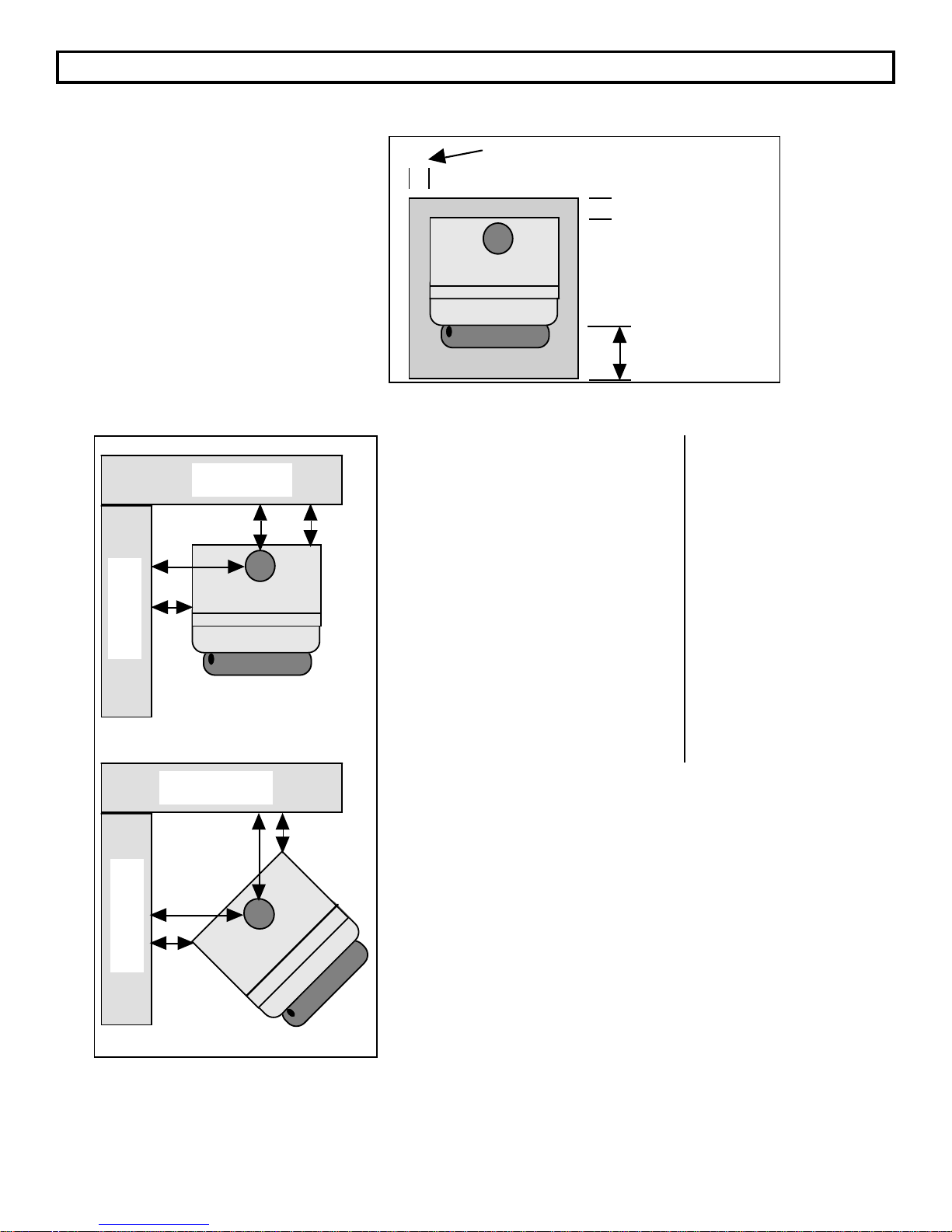
Minimum Alcove Dimensions
Backwall
G
996 Flush Top Flue
Shown Here Ð Follow the
clearances for the 996
Extended 45 Flue when
that model is used.
H
Combustible Alcove
J
996 Flush
Top Flue
996
Extended
45o Flue
D
A
Sidewall
Non-Combustible
Alcove*
BE
D
996 Flush
Top Flue
A
Sidewall
996
Extended
45o Flue
A. Sidewall to unit.............. 14" 16" A. Sidewall to unit.............. 6" 6"
B. Backwall to unit ............. 9 1/2" 14" B. Backwall to unit ............. 2" 4"
D. Connector to sidewall .. 23" 25" D. Connector to sidewall .. 15" 15"
E. Connector to backwall . 10" 10" E. Connector to
G. Max. Depth of Alcove ... 48" 48" G. Max. Depth of Alcove ... 48" 48"
H. Min. Width of Alcove..... 53 1/2" 57 1/2" H. Min. Width of Alcove..... 37 1/2" 37 1/2"
J. Min. Height of Alcove ... 84" 84" J. Min. Height of Alcove ... ** **
* Non-Combustible Alcoves include alcoves made of brick, stone, or concrete with at least 3 1/2" of
thickness along the walls and ceiling that is also spaced and ventilated at least 1" off of the
combustible wall to allow air to move around the non-combustible walls and ceiling.
** 6" Above Stove Top
2 1/2" 2"
backwall................................
Page 27
Page 28

INSERT OPTIONAL EQUIPMENT
Your Avalon 996 appliance comes completely assembled. The options available for the insert method of
installation are listed below and require assembly.
1. Surround Panels - 8", 10", and 12" Sizes (Includes Insulation)
2. Surround Panel Brass Trim (Included with Surround Panels)
3. Blower, Front
1. Surround Panels
The surround panels for your insert are sold separately and come in the three sizes listed below. It is very
important that you choose the surround panels that will adequately suit your installation. For direct or
positive connections the surround panels do not require insulation for an airtight seal. For face seal
connections the surround panels must overlap the fireplace at least 2" on the top and sides and require
insulation to insure an airtight seal.
SURROUND PANEL SIZES SIZE ON INSERT (INCLUDING TRIM)
8" 41 7/8" width by 28 7/8" height
10" 45 7/8" width by 30 7/8" height
12" 49 7/8" width by 32 7/8" height
NOTE: For a Face Seal Connection it is recommended that you have at least 2" of
overlap. On brick or stone facing an overlap of 2 1/2" may be necessary for an airtight
seal due to the rough surface.
It is very important that your surround panels overlap the fireplace opening by 1/4" or more. This will
insure a good seal and provide a more attractive facade. When determining your surround panel size,
remember that the panels must overlap the fireplace opening in both width and height. The surround
panels may overlap the fireplace opening by more than the 1/4" recommendation if it is to allow for a
complete seal. Any questions on selection of the surround panels should be directed towards your
dealer.
To install the surround
panels, first refer to the type
of installation you are using
(e.g. Face Seal Connection,
Direct Connection, etc...).
Follow the directions listed
for the type of installation you
are doing, and follow the
directions below when they
are referred in that section.
The insert will need to be
drawn out of the fireplace at
least 6" to allow for
installation of the surround
panels. If the insert is to be
connected to a flue, the
brass trim and top panel can
be removed with the insert in
its final position to access the
flue and then later reinstalled. If insulation is to
be used and the top panel is
to be removed, make sure to
allow for this by not gluing
the insulation along the top
until the flue is connected.
Refer to the illustration to the
right while installing the
surround panels.
Side Panel
Mounting Angle
(Used only on
Top-Flue models)
Remove
the Button
Plugs
panels and top of insert)
Joggle Clips
Top Panel (Attaches to side
Offset on the top
of side panel
Holes for
Mounting
Side Panel
Side Panel
Page 28
Page 29

INSERT OPTIONAL EQUIPMENT (Continued)
1. Surround Panels (Continued)
1. Remove the two button plugs from each side of the insert with a screwdriver.
2. Using a 5/16" nutdriver or large screwdriver, screw the thread-cutting screws into the four holes
exposed by removing the button plugs. The holes are now pre-threaded, remove the screws.
3. Place one of the side panels against the side of the insert, lining up the slots in the panel with the
threaded holes in the side of the insert. Attach the panel with the thread-cutting screws, leaving the
screws loose enough to adjust the side panel. Repeat for the other side.
4. FOLLOW THE SET OF INSTRUCTIONS FOR THE MODEL BEING INSTALLED:
MODEL: FOLLOW
INSTRUCTIONS:
996 Flush Top Flue 4A
996 Extended 45o Flue 4B
4A. The top mounting angle is designed to stabilize the top panel on the 996 Flush Top Flue
model. Center the mounting angle on the insert with the side that has only three holes in it
facing down. The mounting angle should be flush with the top edge of the top panel on the
insert (see the illustration below). Mark the locations on the insert where the center of the
holes in the mounting angle rest. Remove the mounting angle and drill 11/64" holes where
the marks were placed. Drill only enough to penetrate one layer of metal. Using a 5/16"
nutdriver or large screwdriver, screw the thread-cutting screws into these two holes. The
holes are now pre-threaded, remove the screws. Place the mounting angle back over these
holes and attach it to the insert with the two thread-cutting screws.
Mounting Angle
should be flush
with the edge of
the top panel
Mounting Angle
4B. The top mounting angle is not used on the 996 Extended 45o Flue model. Instead, the brass
trim that runs along the top of the insert must be removed to allow the top panels to slide over
the mounting flange.
5. Slide the top panel onto the offset on top of the side panels. The top panel must also slide over the
mounting flange (or mounting angle on top flue models) that is on the insert. The top panel has four
joggle clips that hold the top panel in place against the insert and the side panels. The best way to
insert the top panel is to hold it at an angle and insert one side first and gradually lower it until the
opposite side is inserted. Adjust the top panel so its edges are flush with the side edges of the side
panels.
6. Adjust the position of the side panels so they are: 1) flush with the bottom of the insert; 2) both the
same distance back from the front of the insert; 3) perpendicular to the floor.
Page 29
Page 30

INSERT OPTIONAL EQUIPMENT (Continued)
1. Surround Panels (Continued)
INSULATION INSTALLATION INSTRUCTIONS
The installation of the insulation is required only for face seal connections. Direct and positive
connections do not require the insulation to be installed. Refer to the owner's manual for more details on
the type of installations available and the items that are required for each type of installation.
1. With the insert drawn at least 6" away from the fireplace, glue the insulation strip included with the
surround panel kit to the back of the panels using RTV silicon or stove gasket cement. The insulation
should be installed so it overlaps the fireplace opening to form a seal between the panels and the
fireplace face.
2. Push the insert into the fireplace, ensuring a seal is made with the insulation between the panels and
the fireplace face.
2. Surround Panel Brass Trim (Included with Surround Panels)
The brass trim kit is included with the surround panel kit and includes all of the items needed for
installation.
1. Lay the three pieces of brass trim on the floor in front of the insert. Arrange the brass trim so that it
resembles the illustration below. The rounded edge of the trim that will be facing outwards when
installed should be facing down.
CROSS SECTION OF BRASS TRIM
Screw holds "L"
Bracket to Trim
"L" Bracket slides into
this groove
Surround Panels
slide into this
groove
Rounded portion
faces outward
when installed
Lay the trim on the floor in
front of the insert with the
rounded portion facing down.
Insert
Side Trim
"L" Brackets
Top Trim
2. Insert an "L" bracket leg into the groove in the 45o cut end of each side piece. Slide the other leg of
each "L" bracket into the groove in each end of the top piece.
3. With a small screwdriver tighten the screws into the "L" brackets, ensuring that the 45
o
cuts are butted
together to form a neat joint.
4. Lift the complete brass trim assembly and slide the side pieces down over the edge of the side panels
until the bottom edge of the brass trim is flush with the bottom of the side panels and the top panel is
in the groove of the top brass trim piece.
Page 30
Page 31

INSERT OPTIONAL EQUIPMENT (Continued)
3. Blower, Front
The front blower is designed to improve your appliance's natural convection by pushing heated air
through the convection chamber and out of the vents along the top.
BLOWER ASSEMBLY
Blower Control Knob
Power
Cord
1. Carefully slide the blower assembly underneath the ashlip so that the two clips on the lower back
edge of the blower assembly slide over the front edge of the sheet metal under the appliance. You
should be able to feel the blower assembly snap into place as you slide it in. This is all the assembly
needed to attach the blower assembly.
Rear of Blower
Assembly (Side View)
Clip (One on
each side)
FRONT OF STOVE
Avalon Stove
or Insert
Sheet Metal
Below Ashlip
2. Plug in the blower and test its operation. It should blow air out of the vents on top of the appliance.
The blower is turned off by turning it all the way counter-clockwise. Each click clockwise will increase
the speed of the blower.
Page 31
Page 32

PREPARATION FOR INSTALLATION MASONRY FIREPLACE INSERT
READ THIS ENTIRE MANUAL BEFORE YOU INSTALL AND USE YOUR NEW APPLIANCE. FAILURE TO
FOLLOW INSTRUCTIONS MAY RESULT IN PROPERTY DAMAGE, BODILY INJURY, OR EVEN DEATH.
PREPARATION:
1. Remove all tape and packaging.
2. Remove the wood shipping frame from around and under the appliance.
3. Check that no parts have become loose and the appliance has not been damaged during shipping.
4. Remove the hardware pack from the appliance.
5. READ THE OWNER'S MANUAL BEFORE PROCEEDING.
* Appliance should be located such that no doors, drapes, furniture or other combustibles can be
placed close or swing closer than the minimum 36" clearance.
* The appliance must be installed in a level, secure position.
REQUIRED FLOOR PROTECTION:
NOTE: Minimum hearth extension of 38 5/8" width by 18" depth from fireplace insert door opening is
required.
CHIMNEY LENGTH Maximum Minimum
Vertical 33 Feet 15 Feet
OPTIONS
Your fireplace insert comes completely assembled. Options available for your fireplace insert are:
1. Surround Panels - 8", 10", and 12" Sizes (Brass Trim is included with Surround Panels)
2. Blower, Front
SAFETY
For your safety, examine the fireplace and chimney prior to installation of the insert to determine that they
are free from cracks, loose mortar, creosote deposits, blockages, or other signs of deterioration. If
evidence of deterioration is noted, the insert should not be installed until after repairs have been made.
Any opening between the masonry of the fireplace and the facing masonry must be permanently
sealed.Your fireplace insert is listed for installation into masonry fireplaces, and is approved to be
installed with one of the following connections:
1. Positive
2. Direct
3. Face Seal
NOTE: It is recommended your chimney have a minimum 28 and a
maximum of 144 square inch cross-sectional area to use a face seal
connection, otherwise your chimney may not have sufficient draw for the
fireplace insert to operate correctly. If your chimney does not fit within these
parameters it is recommended you install a direct or positive connection.
When lifting the appliance, you may choose to remove the interior components to make it lighter. Refer to
the section "REPLACEMENT PARTS AND REMOVAL INSTRUCTIONS" for the proper sequence of
removal and replacement of internal components.
Page 32
Page 33

FIREPLACE INSERT - SPECIFICATIONS
LOCATION OF FLUE COLLAR DIMENSIONS REQUIRED FOR INSTALLATION INTO FIREPLACE AND
PANEL SIZING. WHEN INSTALLING THE 996 EXTENDED 45
DISTANCE THAT THE 45
o
ELBOW WILL EXTEND PAST THE BACK OF THE INSERT.
o
FLUE, MAKE ALLOWANCE FOR THE
TOP VIEW
996 Flush Top Flue 996 Extended 45o Flue
15"
Firebox Front
25 5/8"
12 13/16"
4"
19
3/8"
10
3/8"
24
1/8"
25 5/8"
12 13/16"
3 5/8"
19
3/8"
24
1/8"
Firebox Front
FIREPLACE SIZING
Measure and center the appliance into the fireplace based on the provided measurements.
A. Minimum Height
(Front)
B. Minimum Height
(Back)
C. Minimum Width (Front)
D. Minimum Width (Back)
E. Depth into Fireplace
996
Flush
Top Flue
21 3/4"
21 3/4"
25 5/8"
25 5/8"
14"
5 3/8"
996
Extended
o
Flue
45
21"
21"
25 5/8"
25 5/8"
9 3/8"
10"
D
B
E
F
C
F. Extension onto Hearth
A
Page 33
Page 34
FIREPLACE INSERT - SPECIFICATIONS (Continued)
FLOOR PROTECTION:
Hearth of 38 5/8" width and 18" depth when the insert is in place (see "E" and "F" below).
CLEARANCE TO COMBUSTIBLES:
996
Flush
Top
996
Extended
o
45
Flue
Flue
A. Adjacent
Sidewall to Insert
B. Side Facing
14"
13"
14"
13"
COMBUSTIBLE MANTLE
Combustible Surface
D
C
C. Top Facing
(Facing with
29 1/2"
14 1/2"
29 1/2"
14 1/2"
Shield)
D. Mantle to Insert
(Mantle with
Shield)
E. Minimum Floor
Protection-Front
F. Minimum Floor
Protection-Side
31 1/2"
16 1/2"
18"
8"
31 1/2"
16 1/2"
18"
8"
Combustible Surface
Fireplace Facing
A
COMBUSTIBLE SIDEWALL
Surround Panel
F
B
E
NOTE: For clearances, use this clearance diagram or the clearance diagram on the safety label attached
to the back of the appliance.
LEVELING BOLTS
If your fireplace is stepped down from the hearth, you will be required to use the leveling bolts located
within the hardware package.
Prior to placing the insert
BOTTOM VIEW
in the fireplace opening,
measure the step-down.
Screw the 1/2" bolts
provided into the threaded
holes in the back corners
Leveling
Bolts
of the insert body and
adjust them to match the
step-down measurement.
As you install the insert the
leveling bolts may need
further adjustment. This
may be done by tilting the
insert slightly and turning
the bolts.
Page 34
Page 35

MASONRY FIREPLACE INSERT INSTALLATION
Installation Using a Direct Connection
Using the direct connection between your insert and masonry chimney allows you to use your existing
chimney with a minimum of installation work. An airtight seal must be made with a block-off plate to insure
that your chimney will draw the smoke out of the appliance. The directions below illustrate one way to
install your insert into a direct connection masonry chimney. There are other alternative methods. Check
with your dealer or installer for information on other options available to you. The directions below should
be followed in the order listed.
1. Inspect the masonry chimney and follow all the rules outlined in the section titled "CHIMNEY
INFORMATION & REGULATIONS".
2. Follow the directions for making a block-off plate in the section titled "INSTALLATION OF A
FIREPLACE BLOCK-OFF PLATE".
3. Follow all of the regulations and guidelines specified in the sections titled "FIREPLACE INSERT SPECIFICATIONS" and "PREPARATION FOR INSTALLATION - MASONRY FIREPLACE INSERT".
4. Once the plate is in position, slide the
Block-off Plate
pipe into the plate up through the
damper. It must extend up to the flue
liner or at least one foot past the block-off
plate.
5. You may now place your new appliance
into the fireplace opening and position
the connector pipe so that it can be
easily pushed into the flue opening on
top of the insert. You may want to use a
towel or blanket to protect the floor while
positioning the insert.
6. Once this has been accomplished, reach in and pull the connector pipe down into the flue of the
insert. If ample room between the top of the insert and the fireplace opening does not exist, you will
need to remove the top firebricks by following the directions in the section "REPLACEMENT PARTS
AND REMOVAL INSTRUCTIONS". Then reach inside the appliance and pull the connector down by
placing your hand up through the flue opening of the appliance. The chimney connector should fit
tight and secure into the flue opening.
7. With the connector in place, you have now completed the direct connection for your insert. It is a good
idea to check your connection by trying to rock the chimney connector back and forth. If it feels snug,
a good connection is established. If you can feel some play when you rock it back in forth, make sure
that the insert is properly aligned and that the connector fits tight in the flue collar on top of the insert.
8. Take a look at the figure on the following page. Make sure all of the items listed are complete.
Page 35
Page 36

MASONRY FIREPLACE INSERT INSTALLATION (Cont.)
Installation Using a Direct Connection (Continued)
9. To install the surround panels, follow the directions listed in the section "INSTALLING SURROUND
PANELS" . NOTE: Surround panels are not required for a direct connection if a block-off plate is
used.
Follow the installation instructions in reverse order for periodic inspection and cleaning.
SIDE VIEW OF FIREPLACE INSERT DIRECT CONNECTION
Clay Flue Liner with
Required Air Space
Stainless Steel
Chimney Connector
Must Extend to Clay
Flue Liner or at least
one foot beyond
Block-off Plate
Airtight Insulated
Clean-Out
Remove Damper or
Wire it Open
Block-off Plate
Insulation
(Optional)
Block-off Plate
Insulation
Optional Surround
Panel
Non-Combustible
Material
18" Min.
Follow the directions on the previous page for installation.
996 Extended 45 Flue Shown
Here Ð Follow the clearances
for the 996 Flush Top Flue
when that model is used.
Page 36
Page 37

MASONRY FIREPLACE INSERT INSTALLATION (Cont.)
Installation Using a Positive Connection
Using a positive connection between your insert and masonry chimney allows you to use your existing
masonry chimney to support a new factory-built chimney liner. The advantages of a positive connection
are excellent chimney draft and ease of cleaning. A block-off plate is not needed for this type of
installation because the positive connection provides sufficient draft. If one is used, it need not be airtight.
The directions below illustrate one way to install your positive connection. There are several other
alternative methods. Check with your dealer or installer for information on other options available to you.
1. Install the positive connection (full reline) through the masonry chimney according to the
manufacturer's instructions for installation and support. Make sure to follow all of the manufacturer's
safety precautions during assembly. Inspect the masonry chimney and positive connection so that all
of the rules outlined in the section titled "CHIMNEY INFORMATION & REGULATIONS" are met.
2. If a block-off plate is desired (optional), follow the directions for making a block-off plate in the section
titled "INSTALLATION OF A FIREPLACE BLOCK-OFF PLATE".
3. Follow all of the regulations and guidelines specified in the sections titled "FIREPLACE INSERT SPECIFICATIONS" and "PREPARATION FOR INSTALLATION - MASONRY FIREPLACE INSERT".
4. If you are using a block-off plate, slide
Block-off Plate
the pipe into the plate up through the
damper. If you are not using a block-off
plate, make sure the last segment of the
positive connection will reach the insert
once it is inserted into the fireplace.
5. You may now place your insert into the
fireplace opening and position the
connector pipe so that it can be easily
pushed into the flue opening on top of
the insert. You may want to use a towel
or blanket to protect the floor or panel
finish while positioning the insert.
6. Once this has been accomplished, reach in and pull the connector pipe down into the flue of the
insert. If ample room between the top of the insert and the fireplace opening does not exist, you will
need to remove the top firebricks by following the directions in the section "REPLACEMENT PARTS
AND REMOVAL INSTRUCTIONS". Then reach inside the appliance and pull the connector down by
placing your hand up through the flue opening of the appliance. The chimney connector should fit
tight and secure into the flue opening.
7. With the connector in place, you have now completed the positive connection for your insert. It is a
good idea to check your connection by trying to rock the chimney connector back and forth. If it feels
snug, a good connection is established. If you can feel some play when you rock it back in forth,
make sure that the insert is properly aligned and that the connector fits tight in the flue collar on top of
the insert.
Page 37
Page 38

MASONRY FIREPLACE INSERT INSTALLATION (Cont.)
Installation Using a Positive Connection (Continued)
8. Take a look at the figure below. Make sure all of the items listed below are completed.
Must be sealed at
the top (preferable)
or with a block-off
plate
Stainless Steel
Chimney Liner System
Follow Liner
Manufacturer's
Instructions on
Installation and
Support
Airtight Insulated
Clean-Out
Remove Damper or
Wire it Open
Insulation
(Optional)
Optional Face Seal
Non-Combustible
Material
18" Min.
996 Extended 45 Flue Shown
Here Ð Follow the clearances
for the 996 Flush Top Flue
when that model is used.
9. To install the surround panels, follow the directions listed in the section "INSTALLING SURROUND
PANELS" .
Follow the installation instructions in reverse order for periodic inspection and cleaning.
Page 38
Page 39

MASONRY FIREPLACE INSERT INSTALLATION (Cont.)
Installation Using a Face Seal Connection
NOTE: It is recommended your chimney have a minimum 28 and a maximum of 144
square inch cross-sectional area to use a face seal connection, otherwise your chimney
may not have sufficient draw for the fireplace insert to operate correctly. If your chimney
does not fit within these parameters it is recommended you install a direct or positive connection.
Using a face seal connection allows you to use your existing masonry chimney with your new insert. The
advantages of a face seal connection are ease of installation and low cost. The directions below illustrate
the way to install a face seal connection with your insert.
1. Inspect the masonry chimney to make sure the fireplace meets all of the rules outlined in the section
titled "CHIMNEY INFORMATION & REGULATIONS". Make sure the fireplace and chimney are
thoroughly cleaned and in good condition.
2. Follow all of the regulations and guidelines specified in the sections titled "FIREPLACE INSERT SPECIFICATIONS" and "PREPARATION FOR INSTALLATION - MASONRY FIREPLACE INSERT".
3. Wire open or remove the fireplace damper
4. Follow the directions specified in the section titled "SURROUND PANEL INSTALLATION" for
installation of the panels and the insulation. Insulation between the surround panels and the facing
of the fireplace is required.
5. Take a look at the figure below. Make sure all of the items listed are completed.
Airtight Insulated
Clean-Out
Remove Damper or
Wire it Open
Insulation
(Required)
Face Seal (2" to
2 1/2" Overlap)
Non-Combustible
Material
18" Min.
996 Extended 45 Flue Shown
Here Ð Follow the clearances
for the 996 Flush Top Flue
when that model is used.
Follow the installation instructions in reverse order for periodic inspection and cleaning.
Page 39
Page 40

INSTALLATION OF A FIREPLACE BLOCK-OFF PLATE
A block-off plate is used to prevent the exhaust going into a masonry fireplace from entering the inside of
the house. It ensures a tight seal between the masonry fireplace and the stove pipe leading through it. A
properly made block-off plate, coupled with either a positive or direct connection, provides the wood
heating appliance with a vacuum draw that pulls the flue gases out of the appliance and out the top of the
chimney. The directions below show how a block-off plate is made.
1. Measure below damper area the width from side to side at rear of smoke chamber. Label this
Measurement "A".
2. Measure the width below damper area from side to side at front of smoke chamber. Label this
Measurement "B".
3. Measure the depth below damper front to back of smoke chamber. Label this Measurement "C".
4. Make a template of your measurements, but add 2" to each of the sides.
CROSS SECTION OF FIREPLACE
A
B
C
Your template should resemble the drawing on the next page with the dotted lines indicating your initial
measurements and the solid line indicating the additional 2". You will use this template to cut a piece of
sheet metal (minimum 24 gauge) to install in your smoke chamber.
The solid line will represent the shape of the piece of sheet metal cut while the dotted line will represent
where you will bend the sheet metal for installation. Mark the position of several holes on each side to
suit your specific installation, and drill 1/4" diameter holes.
Page 40
Page 41

INSTALLATION OF A FIREPLACE BLOCK-OFF PLATE
(Continued)
Measurement "A"
Measurement "C"
} 2 "
Measurement "B"
5. Bend the sheet metal as indicated on the template at a 45 degree angle on each side after cutting the
sheet metal (This 2" lip will allow you to screw this plate into the smoke chamber inside your
fireplace). The 2" lip with the 1/4" diameter holes will allow you to screw the plate to the firebox walls.
6. Determine the position of where to cut the 6-1/4" hole in the sheet metal plate so that it lines up with
the chimney flue opening and the final position of the wood burning appliance, then cut the hole. If
you are installing surround panels with your insert, refer to the section "SURROUND PANEL
INSTALLATION" for how to position your insert correctly.
7. Put the plate in position and drill the mounting holes. Then bolt into position using the mounting bolts.
The seal can be completed by using fiberglass insulation and/or furnace cement between the
masonry and the block-off plate.
NOTE: Allow the furnace cement to cure for 12 to 24 hours before starting a fire.
Page 41
Page 42

PREPARATION FOR INSTALLATION ZERO CLEARANCE (METAL) FIREPLACE
READ THIS ENTIRE MANUAL BEFORE YOU INSTALL AND USE YOUR NEW APPLIANCE. FAILURE TO
FOLLOW INSTRUCTIONS MAY RESULT IN PROPERTY DAMAGE, BODILY INJURY, OR EVEN DEATH.
PREPARATION:
1. Remove all tape and packaging.
2. Remove the wood shipping frame from around and under the appliance.
3. Check that no parts have become loose and the appliance has not been damaged during shipping.
4. Remove the hardware pack from the appliance.
5. READ THE OWNER'S MANUAL BEFORE PROCEEDING.
* Appliance should be located such that no doors, drapes, furniture or other combustibles can be
placed close or swing closer than the minimum 36" clearance.
* The appliance must be installed in a level, secure position.
REQUIRED FLOOR PROTECTION:
NOTE: Minimum hearth extension of 38 5/8" width by 18" depth from fireplace insert door opening is
required.
CHIMNEY LENGTH Maximum Minimum
Vertical 33 Feet 15 Feet
OPTIONS
Your fireplace insert comes completely assembled. Options available for your fireplace insert are listed
below. Installation instructions for these options are in the section "INSERT OPTIONAL EQUIPMENT".
1. Surround Panels - 8", 10", and 12" Sizes (Brass Trim is included with Surround Panels)
2. Blower, Front
SAFETY
For your safety, examine the fireplace and chimney prior to installation of the appliance to determine that
they are free from cracks, creosote deposits, blockages, or other signs of deterioration. If evidence of
deterioration is noted, the insert should not be installed until after repairs have been made.
Your Avalon 996 is listed for installation into the following brands of zero clearance (metal) fireplaces.
¥ Marco ¥ Majestic ¥ Heatilator
¥ Preway ¥ Tempco ¥ Superior
When lifting the appliance, you may choose to remove the interior components to make it lighter. Refer to
the section "REPLACEMENT PARTS AND REMOVAL INSTRUCTIONS" for the proper sequence of
removal and replacement of internal components.
Page 42
Page 43

ZERO CLEARANCE (METAL) FIREPLACE - SPECIFICATIONS
LOCATION OF FLUE COLLAR DIMENSIONS REQUIRED FOR INSTALLATION INTO FIREPLACE AND
PANEL SIZING. WHEN INSTALLING THE 996 EXTENDED 45
DISTANCE THAT THE 45
o
ELBOW WILL EXTEND PAST THE BACK OF THE INSERT.
o
FLUE, MAKE ALLOWANCE FOR THE
TOP VIEW
996 Flush Top Flue 996 Extended 45o Flue
15"
Firebox Front
25 5/8"
12 13/16"
4"
19
3/8"
10
3/8"
24
1/8"
25 5/8"
12 13/16"
3 5/8"
19
3/8"
24
1/8"
Firebox Front
FIREPLACE SIZING
Measure and center the appliance into the fireplace based on the provided measurements.
A. Minimum Height
(Front)
B. Minimum Height
(Back)
C. Minimum Width
(Front)*
D. Minimum Width
(Back)*
996
Flush
Top Flue
21 3/4"
21 3/4"
27 5/8"
27 5/8"
15"
5 3/8"
996
Extended
o
Flue
45
21"
21"
27 5/8"
27 5/8"
10 3/8"
10"
D
B
E
F
C
A
E. Depth into Fireplace*
F. Extension onto Hearth
* These dimensions include the 1" air space required between the sides and back of the insert and the
metal firebox of the zero clearance (metal) fireplace.
Page 43
Page 44

ZERO CLEARANCE (METAL) FIREPLACE - SPECIFICATIONS
(Continued)
FLOOR PROTECTION:
Hearth of 38 5/8" width and 18" depth when the insert is in place (see "E" and "F" below).
CLEARANCE TO COMBUSTIBLES:
996
Extended
o
45
Flue
30"
12"
COMBUSTIBLE MANTLE
Combustible Surface
D
A. Adjacent
Sidewall to Insert
B. Side Facing
996
Flush
Top Flue
30"
12"
C
C. Top Facing
D. Mantle to Insert
E. Minimum Floor
Protection-Front
F. Minimum Floor
12"
24"
18"
8"
12"
24"
18"
8"
Combustible Surface
Fireplace Facing
A
Surround Panel
B
Protection-Side
COMBUSTIBLE SIDEWALL
F
E
NOTE: For clearances, use this clearance diagram or the clearance diagram on the safety label attached
to the back of the appliance.
LEVELING BOLTS
If your fireplace is stepped down from the hearth, you will be required to use the leveling bolts located
within the hardware package.
Prior to placing the insert
BOTTOM VIEW
in the fireplace opening,
measure the step-down.
Screw the 1/2" bolts
provided into the threaded
holes in the back corners
Leveling
Bolts
of the insert body and
adjust them to match the
step-down measurement.
As you install the insert the
leveling bolts may need
further adjustment. This
may be done by tilting the
insert slightly and turning
the bolts.
Page 44
Page 45

ZERO CLEARANCE (METAL) FIREPLACE INSTALLATION
Your new wood burning insert is approved for use in suitable zero clearance (metal) fireplaces. Make
sure to follow all of the steps listed below to insure proper installation. The installation technique below
illustrates one way of installing your insert. Check with your dealer or installer for information on other
installation options available to you.
1. Inspect the chimney and make sure it follows all the rules outlined in the section titled "CHIMNEY
INFORMATION & REGULATIONS".
2. Follow all of the regulations and guidelines specified in the sections titled "ZERO CLEARANCE
(METAL) FIREPLACE INSERT - SPECIFICATIONS" and "PREPARATION FOR INSTALLATION ZERO CLEARANCE (METAL) FIREPLACE INSERT ". Make sure that your brand of zero clearance
(metal) firepalce matches one that is listed. Check with your dealer or installer if there are any
discrepencies.
3. The next step in installing a zero clearance insert is to remove all of the unnecessary components on
your brand of fireplace. Because of the wide differences between fireplace brands and models, it
would be difficult to list all the variations. Below, we have provided a generic view of a typical zero
clearance fireplace to illustrate which parts may or may not be removed.
Parts that
1. Damper plate (Must be removed)
2. Smoke shelf
3. All internal baffles
4. Grates (Must be removed)
5. Metal Screen
6. Glass Screen or Doors
Parts that
removed:
¥ Masonry lining or firebricks
¥ Any insulating materials.
¥ Any structured rigid frame
members (metal sides, floor, door
frame, face of fireplace, etc.)
NOTE: The installation of the decorative panels and trim is optional and not required. An alternative to
using the decorative panels is to simply draw the fireplace screens closed around the insert.
4. THE ZERO CLEARANCE FIREPLACE MUST BE INSTALLED WITH A STAINLESS STEEL STARTER
PIPE THAT PENETRATES BEYOND THE SMOKE SHELF AND IS DIRECTLY CONNECTED TO THE
FIREPLACE CHIMNEY. You may want to construct a steel block off plate and install it or use a pipe
adaptor to fill the gap between the fireplace chimney and the 6" stainless steel starter pipe that you
will be installing. See the illustration of a block-off plate example on the next page for what a block-off
plate should look like in a zero clearance (metal) fireplace.
may be removed:
may not be
5 3
2
6
4
1
5. Allow a minimum of 1" on each side of the plate larger than the outside dimension of the chimney flue
diameter. The 1" overlap of the block off plate is required to properly seal the gap between the
chimney and the 6-1/4" hole in the block off plate.
Page 45
Page 46

ZERO CLEARANCE (METAL) FIREPLACE INSTALLATION
(Continued)
6. After the plate has been trimmed, drill four 1/8"
holes in the plate as shown. These holes will be
used for mounting the plate to the inside of the
fireplace.
7. Place the plate inside the fireplace over the
chimney flue centering the 6-1/4" hole in the
chimney flue exit. Mark the location of the 1/8"
mounting holes on the inside top of the fireplace.
Drill the holes with a 1/8" drill bit.
8. Put the starter pipe through the block off plate,
leaving enough sticking through to allow it to be
connected to the appliance.
9. You can now place your appliance into the
fireplace opening and position the starter
pipe so it can be easily pushed into the flue
opening on top of the insert.
10. If the stove needs to be leveled, follow the
directions for using the leveling bolts
described in the specifications portion for
zero clearance installation.
BLOCK-OFF PLATE
14"
6-1/4"
1/8" Holes
14"
11. Once the insert is in position and leveled, connect the 6" liner to the unit and secure it with sheet metal
screws through the holes in the flue collar.
Install Screws in
Flue Collar
12. To install the surround panels or front blower, follow the directions listed in the section "INSERT
OPTIONAL EQUIPMENT". NOTE: Insulation for the surround panels is not required.
Page 46
Page 47

OPERATING YOUR APPLIANCE
Location and Use of Controls
Combustion Air Control
The Combustion Air Control is located on the lower right side. It is controlled by rotating it up and down.
When it is completely down, it is in the fully closed position. In the upwards position it is in the fully open
position, allowing for the most amount of air into the firebox, increasing combustion.
The Combustion Air Control
is operated by rotating it up
or down. In the down
position it is fully closed. In
the up position it is fully
open.
Page 47
Page 48

OPERATING YOUR APPLIANCE (Continued)
To build a fire in disregard of the information provided in this section can cause
permanent damage to your appliance and void your warranty.
This appliance is not designed for use with the door open. Burning with the loading door open could
create a safety hazard.
Burning Procedure
1. Open the door and place some paper and kindling or a solid, wax impregnated firestarter inside the
appliance.
2. Make sure that the combustion air intake control is fully open by rotating the control knob all the way
up.
3. Now light the fire. Once the kindling is burning, add some small dry pieces of wood and close the
loading door. NOTE: The first two or three fires in your new appliance will cause the high temperature
paint to give off a slight odor and a small amount of smoke. This is the paint curing. For best results
during the curing of the paint, burn small intense fires so the appliance does not overheat. The high
temperature paint cures best at medium temperatures. Also, the viewing glass may become
somewhat obscure the first few times, as your appliance is drying all moisture from bricks and even
the steel itself.
4. Next add two or three medium size dry logs (use of green or wet wood in your appliance will develop
creosote, cloud glass, and greatly decrease its efficiency). At this time establish a hot fire with a bed
of red hot coals.
5. To slow the rate of burn, you can close (rotate down) the combustion air intake control (lower right of
the appliance) as needed.
NOTE: Over-restricting the amount of combustion air into the appliance will cause creosote build-up on
glass and in the appliance and flue. This will also greatly decrease the efficiency of the
appliance.
Do not open the door of your appliance when the air control inlet is fully closed. There is
a possibility with a solid fuel burning appliance that doing so could result in a sudden
flash of flames as the fire ignites with oxygen. However, your Avalon 996 has been
thoroughly safety tested to reduce this possibility.
If your home is a new, airtight energy efficient home, you may have to supply an outside
air inlet to prevent possible air starvation to appliance.
Page 48
Page 49

OPERATING YOUR APPLIANCE (Continued)
Burning Your Appliance Efficiently
Your Avalon 996 is designed to heat your home efficiently with the lowest amount of creosote build-up
and pollutants emitted. The following steps provide a guideline to efficient burning:
On cold days, when you wish for high heat output from your appliance, load the appliance fully after the
fire has been established and burn at a medium-high to high burn mode. When a comfortable heat level
in your home has been reached, subsequent loadings would be of lesser amounts of wood. On warmer
days, burn smaller fires, using less wood. This method will give you the most efficient burn possible.
Although the fire will burn longer at a lower setting, your appliance will not produce as much heat and it
will increase soot accumulation on the appliance, chimney and glass.
For an overnight burn, establish a hot fire. Before you are ready to retire, completely fill the appliance with
wood. With the controls in the fully open position, let the fire burn intensely for 20-30 minutes. Next adjust
the combustion air control so that a low, lazy flame is visible. You should be able to maintain a fire for
about 9 hours, depending on the type of wood used, and still have a coal bed, with no visible flame, left to
start the morning fire. To re-establish a fire after an overnight burn, open the controls fully and stir the
ashes to bring hot coals to the surface. Then follow the instructions under "first fire". If you dampen the
fire down too low, you will not only lower the heat output, but you will be promoting creosote build-up. It
will take a few days of practice to achieve the desired settings.
APPROXIMATE COMBUSTION AIR CONTROL SETTINGS
TYPE OF BURN RATE AIR CONTROL SETTING
Overnight Burn ................................................................................ Fully Closed
Medium Burn ................................................................................... 1/64" to 1/32" Open
Medium High Burn.......................................................................... 1/32" to 1/16" Open
High Burn ......................................................................................... Fully Open
Daily Use of Your Appliance
During daily use of your appliance you will learn what rates of burn best accomodate your heating needs.
A stove thermometer is highly recommended. Approximate low burn is 300 degrees F., approximate
medium burn is 500 to 600 degrees F. and approximate high burn is 800 degrees F. with the thermometer
located on the top of the appliance.
Some helpful hints: After loading your appliance, open the air control and allow your appliance to burn
vigorously for 20 to 30 minutes. This will assist in the burn-off of any creosote which accumulates over
periods of extended use at low settings.
Page 49
Page 50
OPERATING YOUR APPLIANCE (Continued)
Wood
This appliance is designed to burn natural wood only. Higher efficiencies and lower emissions generally
result when you burn air dried, seasoned hardwoods as compared to softwoods or to green or freshly cut
hardwoods. DO NOT BURN treated wood, garbage, solvents, trash, coal, cardboard, colored paper, or
wax impregnated logs (i.e. Duraflame, etc.). Burning treated wood, garbage, solvents, colored paper or
driftwood from salt water may result in release of toxic fumes and may render the appliance ineffective
and void the limited warranty. Burning coal, cardboard or loose paper can produce soot, large flakes,
char or fly ash that can coat the inside of your appliance, causing smoke spillage into the room.
Choosing the kind of firewood to burn in your appliance depends on what is available to you. If all you
can obtain is softwoods, obviously, that will be your choice.
Softwoods such as pine and fir are easily ignited and burn rapidly with hot flames. Since they burn so
easily and quickly you will have to spend more time loading your firebox, especially in the high burn
mode. With softwoods it will be much more difficult to achieve an overnight burn. Furthermore, softwoods
make it necessary to reload the appliance more often. The chart below outlines the advantages of using
hardwood.
SPECIES* LBS./CORD** BTU's/CORD** Hours per Cord at 40,000 BTU's
per Hour**
ALDER
APPLE
ASH
BIRCH
CEDAR
COTTONWOOD
DOGWOOD
ELM
FIR, DOUGLAS
HEMLOCK
MAPLE
OAK, RED
OAK, WHITE
PINE
REDWOOD
SPRUCE
* At 20% moisture content
** All values are approximate
2540 19,050,000 476
4400 33,000,000 825
3440 25,800,000 645
3040 22,800,000 705
2060 15,450,000 386
2160 16,200,000 405
4320 31,725,000 793
2260 16,950,000 423
2970 22,275,000 556
2700 20,250,000 506
3200 24,000,000 600
3680 27,600,000 690
4200 31,500,000 787
2250 16,875,000 421
2400 18,000,000 450
2240 16,800,000 420
If you have a choice it is best to use the more dense hardwoods for a longer lasting fire. The best
arrangement is to have a mix of softwoods and hardwoods for ease of start-up and a longer lasting fire.
Also, it is a good idea once the fire is established to use larger diameter logs stacked tightly together. This
will promote a longer burn time.
Wood is typically sold by the "cord". A cord is a nicely stacked pile of logs measuring 4 feet wide by 4 feet
high by 8 feet long. Always look for the driest wood especially if you purchase your wood by weight.
Unseasoned, wet wood is much heavier.
Moisture content of the wood greatly affects the way any appliance operates. Well seasoned wood (split,
stacked and kept dry for at least 12 months) is your best fuel choice.
Page 50
Page 51

OPERATING YOUR APPLIANCE (Continued)
Wood (Continued)
Wet wood not only causes more work for you due to the increase in weight making it more burdensome to
carry, but most importantly it will not burn as efficiently. You will receive less heat output from a wet piece
of wood because it wastes energy evaporating the water, energy that should be used for heating your
home. When a wet piece of wood is placed in your appliance it will also cause more creosote
accumulation on the glass, in the appliance, flue and chimney. The primary reason for this is, as the water
evaporates from the wood it will "spit" creosote-like material. If you can hear your wood sizzle or you can
see moisture bubbling from the ends of the logs placed in a HOT appliance, your wood is too wet!
Another big advantage to burning seasoned wood, aside from higher efficiency and less creosote, is
LESS POLLUTION!
Seasoning Wood
Green wood will burn, but seasoned or dry wood is lighter, has more heat value, and is less apt to form
creosote deposits. Any moisture in the wood reduces the recoverable heat because water absorbs heat
in the process of being changed to steam. The net heat from a pound of completely dry (no moisture)
hardwood is about 7,950 BTU's. All wood has some moisture in it which reduces the net usable heat at a
rate of 1,200 BTU's per pound of water.
The moisture in the wood of living trees varies among species, within a species, and even within
individual trees. Frequently, there is a significant difference between the quantity of moisture contained in
the central column of heartwood of a tree and the outer layers of sapwood which is surrounded with bark.
For example, freshly cut American beech has been found to have a heartwood moisture content of 72%.
In contrast, heartwood moisture contents in American elm, northern red oak, and white ash are 95, 80 and
46%, respectively.
When drying wood, the greater the surface area exposed to the air, the more rapid the drying. Therefore,
stack the wood in loose piles that are raised off the ground. Wood greater than 8 inches in diameter or
longer than 4 feet dries very slowly. Reduce the size of such sticks by splitting and/or sawing.
Page 51
Page 52

OPERATING YOUR APPLIANCE (Continued)
Seasoning Wood (Continued)
Place firewood in an open area to obtain rapid drying and to prevent deterioration. Preferably, put a cover
on the top tier of wood. If you cut trees in summer, let them lie for a week. The leaves will draw moisture
from the wood and dry it more quickly than if you limb the tree immediately.
Seasoning can be accelerated greatly by simply stacking fuelwood in a sunny location and then covering
it with clear plastic sheeting. In sunny weather, temperatures within the plastic covering will rise much
higher than outside, warming the wood and evaporating the contained moisture. The water vapor
produced either escapes or condenses on the plastic covering; therefore some arrangement for
ventilation is necessary. It is also desirable to hold the plastic away from the rough ends of the wood to
prevent abrasion, allow air to flow, and keep any condensation from re-wetting the wood.
SOLAR WOOD DRYER
In sunny weather, the temperature within the dryer rises much higher than outside temperatures, warming
the wood and evaporating the contained moisture.
Cover with 4 mil Polyethylene
Air flow
Pr evail ing Win ds
Raise stack off
the ground to
increase air flow
Air flow
Air flow
Many arrangements for plastic covering are possible. Thin 2 millimeter, clear polyethylene sheeting sold
for drop cloths or garden mulching is not recommended because it is easily torn. The 4 millimeter
thickness is more satisfactory and less costly than 6 millimeter. Any clear polyethylene deteriorates badly
after a few months of exposure to full sunlight, so the stack may have to be re-roofed to remain dry over
winter.
Page 52
Page 53
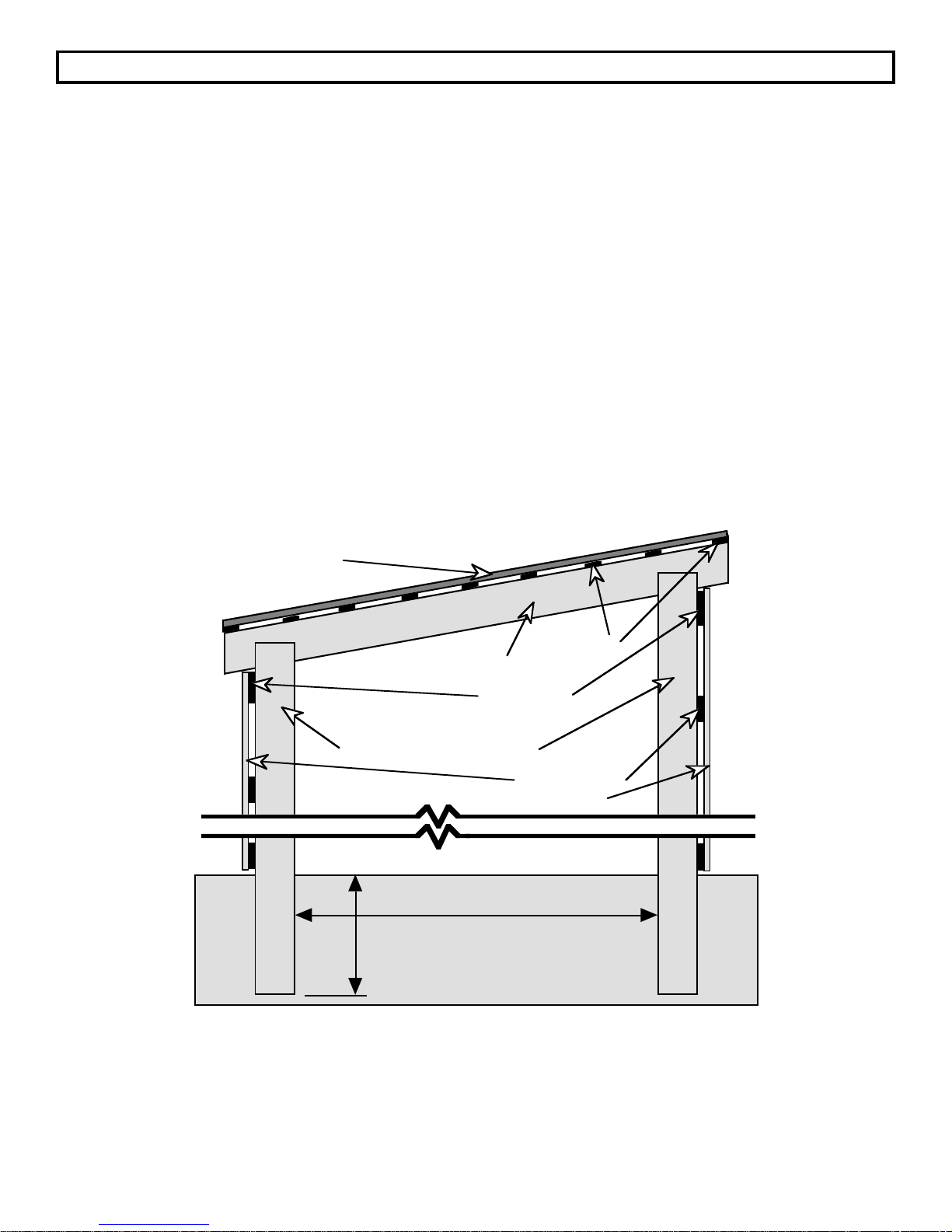
OPERATING YOUR APPLIANCE (Continued)
Seasoning Wood (Continued)
The bathroom scales can be used to check if firewood is still seasoning. Weigh a basket or bag of a few
pieces of firewood. Place them back in the wood pile as an identified unit. Then weigh them again in
about a month. If they have lost weight, the wood is still drying. Cracks that appear in the end of logs are
good signs that the wood is well seasoned.
Generally, wood that is 1) cut to length, 2) split, and 3) stacked in the open, preferably with a cover, during
the winter, should be thoroughly seasoned by the next heating season.
Storing Wood
Firewood is best stored outdoors, under cover and near the house so that valuable space in the house is
not used, insects are kept outside, and the dirt problem is reduced. Store the wood under cover to keep it
dry and its fuel value high. It can be stored in a wood shed, utility building, garage or under a sheet of
plastic or sheet metal roofing.
When drying wood, the greater the surface area exposed to the air, the more rapid the drying. Wood
greater than 8" in diameter or longer than 4' dries very slowly. Reduce the size of such sticks by splitting
and/or sawing. Be sure to keep an air space between the wood and any covering. Stack the wood in
loose piles that are raised off the ground. This will promote air circulation that helps dry the wood.
TYPICAL WOOD SHED
Sheet Metal Roofing
2x6x12 Rafter
2x4 Purlins
2x8x8' Girder
4x4x2 Posts Spaced 8' Apart
Siding and Girts
(Optional)
8' Width
3' Depth
Page 53
Page 54

OPERATING YOUR APPLIANCE (Continued)
Storing Wood (Continued)
If sufficient space is available under a roof, seasoning and storage can be accomplished in one handling.
This practice eliminates the extra handling of moving wood that has been dried outside into a covered
storage area.
Outside, wood will dry to between 14 and 25% moisture content depending on humidity, temperature, and
wind. In a garage or woodshed it may dry to between 10 and 15% moisture content; and wood may dry to
between 5 and 12% in the house.
End braces can be used if you have difficulty stacking wood and if the pile collapses at either end.
Constructed with two-by-fours, end braces are like book ends and can be built to accurately measure a
standard cord. The boards beneath the woodpile keep the bottom row off wet ground.
In some homes a wood box can be constructed inside the house, convenient to the wood appliance and
which has loading access outside. The access door to the wood box from the outside of the house should
be tight fitting.
Page 54
Page 55

OPERATING YOUR APPLIANCE (Continued)
SAFETY IN OPERATION
The Following Safety Rules Should Be Followed Whenever Using Your Appliance:
1. Do not use this appliance for any purpose other than heating. Burn solid
wood fuels only.
2. Never use gasoline, gasoline-type lantern fuel, kerosene, engine oil,
charcoal lighter fluid, or similar liquids to start or "freshen up" a fire. Keep
all such liquids well away from the appliance while it is in use.
3. Do not burn garbage in your appliance, or use chemicals or fluids to start
the fire.
4. Use caution when loading fuel into the appliance after it is already burning
vigorously.
5. Do not over-fire the appliance at any time. If the appliance glows red, it is
over-fired.
6. Keep all household combustibles and appliance fuel at least 3 feet from
the appliance at all times. Store fuel in a dry place well away from the
appliance.
7. Do not support or elevate the fire off of the firebrick. Burn the fire directly
on the bricks. Do not use a grate.
8. Educate your children of the dangers associated with fire and the
presence of a hot appliance. Touching a radiating surface can cause
serious burns. Child guards are available through your dealer.
9. Keep loading door closed at all times except to load fuel.
10. Avoid placing logs and fire against viewing glass.
11. Maintain the door and glass seal and keep them in good condition.
12. Do not modify your combustion air control to allow more air into your
appliance.
13. Do not burn any kind of coal in this appliance.
14. Do not slam door or strike glass.
Page 55
Page 56

CARE AND MAINTENANCE
Maintenance Schedule
The following schedule should be followed to insure your appliance stays in peak condition.
Weekly Maintenance: The following should be done once a week:
ASH DISPOSAL
BRASS CLEANING
GLASS CLEANING
Bi-Monthly Maintenance: The following should be done every two months:
CHECK FOR CREOSOTE
DOOR AND GLASS GASKET INSPECTION
LUBRICATE THE DOOR HINGE AND CONTROLS
Yearly Maintenance: The following should be done after each heating season:
FIREBRICK REMOVAL AND CLEANING
APPLIANCE TOUCH-UP
BLOWER CLEANING (If Applicable)
Maintenance Instructions
ASH DISPOSAL
During constant periods of use ashes must be periodically removed from the appliance to prevent a buildup which will affect the performance and limit the fuel load capacity.
Ashes should be placed in a metal container with a tight fitting lid. The closed container of ashes should
be stored on a non-combustible floor or on the ground, well away from any combustible material, pending
final disposal. If the ashes are to be disposed of by burial in soil or otherwise locally dispersed, they
should be retained in the closed container until all cinders have thoroughly cooled. Other waste must not
be placed in this container.
BRASS CLEANING
Your Avalon 996 may come with a solid brass door, ashlip trim and panel trim, which will require periodic
attention to retain its luster. Use a non-abrasive polish, such as "FLITZ" on the solid brass door and clean
it only when it is cool. A suitable polish is available at your dealer. The brass ashlip and panel trim
should only be cleaned with soap and water. The use of ANY type of brass polish will damage the finish.
GLASS CLEANING
Clean the glass only when the appliance is cool, using a non-abrasive cleaner. If glass cracks or breaks,
let the appliance cool before replacing it. DO NOT OPERATE THE APPLIANCE WITH BROKEN OR
MISSING GLASS. IF THE GLASS DOES BREAK, FOLLOW THE DIRECTIONS IN THE SECTION TITLED
"REPLACEMENT PARTS AND REMOVAL INSTRUCTIONS" FOR REPLACING THE GLASS.
Page 56
Page 57

CARE AND MAINTENANCE (Continued)
DOOR AND GLASS GASKET INSPECTION
A damaged or deteriorated glass or door gasket will allow air to enter the appliance through the space
between the door and firebox. This will allow smoke to enter the room and hamper efficient burning.
Inspect the door gasket to make sure it is flexible and completely intact. Any torn, broken, or flattened
gaskets should be replaced by following the directions in the section titled "REPLACEMENT PARTS AND
REMOVAL INSTRUCTIONS".
DOOR
Door Gasket
Glass Gasket
(Between Glass
and Door)
Ceramic Glass
Glass Clip with
Gasket
Glass Clip Screw
Door Cam &
Assembly
LUBRICATE THE DOOR HINGE AND CONTROLS
It is highly recommended that you periodically lubricate any moving parts such as the door hinges and
combustion air control rod. This will eliminate any scraping or squeaking noises as well as allow the parts
to move freely. A high temperature lubricant, such as Permatex Industrial (R) Anti-seize lubricant, is
required. Graphite or low-temperature lubricants will only last a few days.
CHECK FOR CREOSOTE
Creosote is a tarry liquid or solid resulting from the distilling of wood during the combustion process.
Using wet wood or burning at lower temperatures will result in a heavier creosote deposit. Creosote
vapors will condense in a relatively cool chimney flue of a slow burning fire. As a result, creosote residue
accumulates on the interior surface of the chimney and flue pipes, considerably reducing their diameter.
When ignited, this creosote makes an extremely hot and dangerous fire. The chimney should be
inspected at least once every 2 months during the heating season to determine if a creosote build-up of
approximately 1/4" has accumulated. If this is the case, the creosote should be removed to reduce the risk
of a chimney fire.
Most problems with creosote are due to poor chimneys with low draft and/or cold walls, and to a low rate
of burn when little heat is needed during the spring and fall months. Burning green and resinous wood
also creates creosote.
To prevent creosote accumulation
1. Burn your appliance with the combustion air control wide open for 20 to 30 minutes daily during the
burning season. This will burn out creosote deposits in your appliance.
Page 57
Page 58

CARE AND MAINTENANCE (Continued)
CHECK FOR CREOSOTE (Continued)
2. Burn the appliance with the combustion air control wide open for about 20 minutes every time you
add fresh wood. This allows the wood to achieve the charcoal stage faster and burns the wood
vapors which might otherwise be deposited within the system.
3. Burn only seasoned, dry wood. Seasoned wood is wood that has been dried for at least one year.
4. A small, more intense fire is preferable to a large smoldering one that will deposit creosote within the
system.
5. Establish a routine for using your new appliance. Be aware that the hotter the fire, the less creosote is
deposited on the glass and chimney system. Weekly inspection and cleaning may be necessary
during times of heavy appliance usage. Contact your local fire authority for information on how to
handle a chimney fire. Have a clearly understood plan to handle such a fire.
6. We recommend you have your chimney system and appliance checked and cleaned by a competent
chimney sweep twice a year.
FIREBOX INSPECTION AND CLEANING
At the end of each heating season, remove all of the ash inside the firebox and check for any scale that
may have built up during the heating season. Remove any scale from the inside of the firebox with a wire
brush or scraper. With a flashlight check to see that all of the firebrick lining the firebox is in good
condition. If any of the firebrick is cracked or broken, follow the directions in the section titled
"REPLACEMENT PARTS AND REMOVAL INSTRUCTIONS" for removal and replacement of any
damaged firebrick.
APPLIANCE TOUCH-UP
The outside of the appliance can be touched up using high temperature "Forrest Stove-Brite" paint,
available at your dealer. This will improve the looks of your appliance, but is not necessary. To touch up
paint, first sand the area to be painted with 120 grit sandpaper, clean it with water only, and dry with a
clean cloth. Paint using light covering coats. The newly painted area will appear darker until the paint
goes through the curing process.
BLOWER CLEANING (If Applicable)
You should remove your blower from the appliance at least twice a year for cleaning. Dust will
accumulate on the blower cover as well as the blower motor and impellers. These parts should be
cleaned to insure adequate flow of air and minimize strain on the motor.
Refer to the directions for installing your blower in the section titled "FREESTANDING OPTIONAL
EQUIPMENT" for freestanding models and "INSERT OPTIONAL EQUIPMENT" for insert models . Follow
the directions in reverse order to remove the blower assembly. On freestanding models you need not
remove the thermodisk. Brush away or vacuum all flyash that may have accumulated. Follow the
directions for installing your blower to re-assemble.
Page 58
Page 59

BEFORE CALLING FOR SERVICE
SAVE TIME AND MONEY - CHECK THIS LIST BEFORE YOU CALL FOR SERVICE
To eliminate unnecessary service calls, first read all the instructions in this manual carefully. The
following checklist provides possible solutions to common occurrences that are not the result of defective
workmanship or materials in this appliance.
If you do have a problem that you cannot fix yourself, call the dealer where you purchased your appliance.
When calling, have this manual handy with the model, serial number and purchase date of your
appliance.
Problem Possible Cause Don't Call for Service
Until You Check
Start-up fire extinguishes
itself.
Lazy orange smoky flame. ¥ Bad Fuel.
Smoke smell inside house. ¥ Restricted chimney or
¥ Combustion air inlet
blocked.
¥ Combustion air control
closed.
¥ Restricted Flue.
¥ Poor Draft.
reverse flow (down draft).
¥ Air leak from faulty door or
glass gasket.
¥ Door is out of adjustment.
¥ Combustion air inlet is not
blocked.
¥ Combustion air control is
open.
¥ Wood is dry & seasoned.
¥ Chimney is clean &
unrestricted.
¥ Sufficient chimney length &
correct size.
¥ Chimney is clean &
unrestricted.
¥ Chimney is not receiving a
down draft due to wind or
other obstruction.
¥ Door and glass gasket are
in good condition and
sealing properly.
¥ Door is aligned with the
opening so the door gasket
makes an airtight fit around
the opening.
Appliance won't shut down. ¥ Air leak from faulty door or
¥ Door is out of alignment.
glass gasket.
¥ Door and glass gasket are
in good condition and
sealing properly.
¥ Door is aligned with the
opening so the door gasket
makes an airtight fit around
the opening.
Page 59
Page 60

REPLACEMENT PARTS AND REMOVAL INSTRUCTIONS
Several components inside your appliance are serviceable by you. These components are usually easy
to remove and replace without special tools. Before you attempt to carry out any of these steps, be sure to
read through the entire section. To order new parts, use the chart below to order the appropriate part
number through your dealer. Use only parts from your dealer made specifically for your appliance.
Replacement Parts
Part Name Part Number Part Description
Door Gasket 90-1513 7/8" Dia. Round Fiberglass
Glass Gasket 91-1493 3/8" Flat Fiberglass
Door Glass 91-1491 19 1/8" x 10 1/4"
Firebrick (note size) 90-4000 1 1/4" x 4 1/2" x 9"
Secondary Air Tube 92-5001 21 1/4" Long
Baffle Support Angle 90-5032
Door Handle 90-2050 Wood
Air Control Handle 90-2054 Wood
Owner's Manual 92-3002
Glass Clip with Gasket 92-1480
Ceramic Blanket 90-5040 22 1/2" x 9 1/2"
Door Cam 90-2041 Cast Brass
Removal Instructions
The remaining text in this section details the items below. Make sure to follow the directions closely when
performing any of the procedures. If re-assembly directions are not given with the instructions, reassemble by following the directions in reverse order. All of these procedures can be done without
special tools.
¥ Removing and Replacing the Glass
¥ Removing and Replacing the Glass Gasket
¥ Removing and Replacing the Door Gasket
¥ Removing and Replacing the Firebricks
¥ Removing and Replacing the Secondary Air Tube
Page 60
Page 61

REPLACEMENT PARTS AND REMOVAL INSTRUCTIONS
(Continued)
Removing and Replacing the Glass
DO NOT OPERATE THE APPLIANCE WITH BROKEN OR MISSING GLASS. IF THE GLASS DOES
BREAK, FOLLOW THE DIRECTIONS BELOW FOR REPLACING THE GLASS.
To replace the glass, remove the glass clips on the back of the door by removing the screws. Replace
only with Neoceram 5mm thick, available from your dealer.
The gasket must be placed in the groove provided in the door. Door gaskets to be used are 7/8"
fiberglass weave. Glass gaskets to be used are 3/8" fiberglass weave. Glass clips must have 1/4" selfadhesive fiberglass gasket tape on them before tightening screws (the glass must not touch the door).
DOOR
Door Gasket
Glass Gasket
(Between Glass
and Door)
Ceramic Glass
Glass Clip with
Gasket
Glass Clip Screw
Door Cam &
Assembly
Removing and Replacing the Glass Gasket
A damaged or deteriorated glass gasket will allow air to enter the appliance through the space between
the door and glass. This may cause smoke to enter the room and hamper efficient burning. To replace
the glass gasket, follow the directions for removal of the glass and when re-installing, place the new
gasket in place.
Removing and Replacing the Door Gasket
A damaged or deteriorated glass gasket will allow air to enter the appliance through the space between
the door and firebox. This will allow smoke to enter the room and hamper efficient burning. The door
gasket is held in place with special cement made to withstand extreme heat. To remove the gasket,
carefully pull the gasket away from the door and scrape any excess cement off the door. To replace, use
the manufacturer's gasket and cement (provided by your dealer) and re-attach the gasket, making sure it
is aligned properly around the opening.
Page 61
Page 62

REPLACEMENT PARTS AND REMOVAL INSTRUCTIONS
(Continued)
Removing and Replacing the Firebricks
The firebricks inside your wood-burning appliance assist in retaining heat and create more thorough
combustion inside the firebox. Occasionally one of them may crack and require replacement. The
directions below are divided into three sections, each section addressing either the baffle (top) firebricks,
side and back firebricks, or floor (bottom) firebricks. Before any bricks are removed, make sure the
appliance is cool and cleaned out. The chart below describes the number and size of bricks by
placement.
# of Firebricks Full Size
(9" by 4 1/2" with
a 1 1/4" thickness)
Cut Size (9" by 1 1/2" with
a 1 1/4" thickness)
Cut Size (4 1/2" by 1 1/2"
with a 1 1/4" thickness)
Floor (Bottom) 6 1 1
Baffle (Top) 5
Side and Back 8 1
REMOVING THE BAFFLE (TOP) FIREBRICKS AND COMPONENTS
1. Make sure the appliance is cool and cleaned out.
2. Remove the door by opening it 90 degrees and pulling it upwards. Make sure to grasp the door by
both ends. It is heavy and can be damaged.
3. Note the illustration to the right.
The baffle firebricks can only be
accessed after the ceramic blanket
Ceramic Blanket Holder
Ceramic
Blanket
and holder have been removed.
5
4. Remove the ceramic blanket
holder by reaching into the space
between the door and baffle angle,
grasping the holder and pulling it
2
1
3
4
forward and rotating it down. See
the illustration on the following
page.
Baffle
Support
Angle
5. Remove the ceramic blanket by
pulling it out between the baffle
and door. It can be easily torn, so
use both hands and an even
pulling action.
Firebrick (Underneath Ceramic Blanket)
Ð The front edge rests on the baffle
angle and the back edge on top of the
firebricks at the back of the firebox.
6. Remove each of the baffle firebricks in the order listed on the illustration on the following page. Each
firebrick is removed by pushing it from the bottom and feeding it out of the space between the baffle
and the top of the firebox. The center three firebricks are removed by sliding them to the side first,
then removing them in the same fashion. If the baffle support angle needs to be removed, use a
hammer to knock the baffle support angle upwards and away from the ledge that holds it in place.
Page 62
Page 63

REPLACEMENT PARTS AND REMOVAL INSTRUCTIONS
(Continued)
Removing and Replacing the Firebricks (Continued)
REMOVING THE BAFFLE (TOP) FIREBRICKS AND COMPONENTS (Continued)
7. To reassemble the
baffle
firebricks,
follow the
removal
instructions in
reverse order.
When
inserting the
ceramic
blanket, make
sure it lines
up and is flat
before
installing the
ceramic
blanket
holder.
Remove the ceramic
blanket holder by pulling it
forward and rotating it
downwards and out the
door.
Remove the ceramic
blanket by CAREFULLY
pulling it out of the slot
between the baffle and
the door. Use both hands
and an even pulling action
to prevent tearing.
Remove each of the baffle
firebricks in the order listed here.
Push each firebrick from below so
the front comes off of the baffle.
Then slide it to the side and
towards the front between the
space between the baffle and the
top of the firebox. Slide the center
three firebricks to the side before
removing in the same fashion.
5
4
3
2
1
Baffle
Support
Angle
REMOVING THE SIDE AND BACK FIREBRICKS
1. Make sure the appliance is cool and
cleaned out.
2. Follow the directions for removing the
baffle (top) firebricks. The back edge of
the top firebricks rest on the firebricks at
the back of the firebox and must be
removed prior to removing the side and
back firebricks.
3. Remove the back firebricks in the order
listed in the illustration to the right (bricks
1 through 5).
4. If the side firebricks (bricks 6 through 9 in
the illustration to the right) need removal,
first remove the back firebricks, then
follow the directions for removing the
floor firebricks. The side firebricks are
removed by pivoting them out from the
bottom.
Cut Brick (Only
1 1/2" Wide)
9
1
2
3
8
4
5
7
6
Page 63
Page 64

REPLACEMENT PARTS AND REMOVAL INSTRUCTIONS
(Continued)
Removing and Replacing the Firebricks (Continued)
REMOVING THE SIDE AND BACK FIREBRICKS (Continued)
5. When re-installing the side or back firebricks, make sure to push the firebricks all the way against the
walls of the firebox. This will minimize any movement of the firebricks and reduce chipping.
REMOVING THE FLOOR (BOTTOM) FIREBRICKS
1. Make sure the appliance is cool and cleaned out.
2. Remove the door by opening it 90 degrees and pulling it upwards. Make sure to grasp the door by
both ends. It is heavy and can be damaged.
3. Follow the directions for removing all of the back firebricks. Remove the center forward firebrick by
lifting its front top edge (see illustration below). Do not use any object to pry the firebrick, for this may
cause the firebrick to chip or crack.
4. Remove the rest of the front bricks, one by one, following the order listed in the illustration below.
5. To replace the floor firebricks, follow these directions in reverse order, placing the bricks snug against
the firebox walls.
Cut Brick (Only
1 1/2" Wide)
Cut Brick (Only 1 1/2"
Wide and 4 1/2" Long)
4
2
1
5
6
7
3
8
Page 64
Page 65

REPLACEMENT PARTS AND REMOVAL INSTRUCTIONS
(Continued)
Removing and Replacing the Secondary Air Tube
The secondary air tube is a tube with holes in it that runs along the top of the firebox near the front. Over
time it may wear and become ineffective. The secondary air tube should be replaced if it cracks or shows
severe deterioration, because it supplies air into the firebox that allows for a more efficient fire. The parts
needed to replace the secondary air tube are available from your dealer.
To remove the
secondary air tube, first
Secondary Air Tube
Side of Firebox
remove the two pins
located on the right side
of the firebox that hold
Collar
the tube in place.
These pins are
removed by using a
Pins that hold Secondary
Air Tube and Collar in Place
screwdriver or needlenose pliers to pry them
out of their holes. The
pins are held in place
by flanges on the pins
that expand once they
are pushed into the
hole. Therefore, you
may have to pry with
some amount of force
when trying to remove
them.
Slide collar to the
left after removing
both of the pins.
Short Tube that is
welded to the side
of the firebox
One pin holds the secondary air tube to a collar while the other pin holds the collar to a short tube welded
to the side of the firebox. Once both pins are removed, the collar can be slid to the left and the secondary
air tube and collar can be pulled down and away from the left side. To replace the secondary air tube,
place the collar on the secondary air tube, insert the secondary air tube into the hole on the left side of the
firebox, and slide the collar over to the right so it slides over the short tube that is welded to the right side
of the firebox. Then line up the secondary air tube and collar so the holes for the pins line up and insert
both new pins that are included with the replacement air tube kit.
Page 65
Page 66

5-YEAR WARRANTY
TRAVIS INDUSTRIES, INC. warrants the AVALON 996 appliance to be defect-free in material and workmanship for five (5) years from the date of purchase, with the
exception of the glass, paint, refractory, removable baffle parts and blowers. The blowers and removable baffle parts are warranted for one (1) year from the date of
purchase to be defect - free in material and workmanship. The glass, paint and refractory are not warranted.
Exclusions to this limited warranty include: Injury, malfunction to the product, loss, damage, defect, failure to function due to accident, negligence, misuse, improper
installation, alteration or adjustment of the manufacturer's settings of components, lack of proper and regular maintenance, damage incurred while the appliance is in
transit, alteration, or act of God.
This limited warranty excludes damage caused by normal wear and tear, such as paint discoloration or chipping, worn or torn gasketing, eroded or cracked refractory, etc.
Also excluded is damage to the appliance caused by abuse, improper installation, the use of fuel or fuel loads other than specified by the manufacturer or use not set forth in
the OwnerÕs Manual. An over-fired condition will cause warped metal parts and discolored or burned-off paint.
TRAVIS INDUSTRIES, INC. is free of liability for any damages caused by the appliance, as well as inconvenience expenses, material and labor charges incurred by the
removal or reinstallation of any AVALON appliance. Incidental or consequential damages are not covered by this warranty. In some states, the exclusion of incidental or
consequential damage may not apply.
This warranty does not cover any loss or damage incurred by the use or removal of any component or apparatus to or from the AVALON appliance appliance without the
express written permission of TRAVIS INDUSTRIES, INC. and bearing a TRAVIS INDUSTRIES, INC. label of approval.
Any statement or representation of AVALON products and their performance contained in AVALON advertising, packaging literature, or printed material is not part of this
limited warranty.
This warranty is automatically voided if the applianceÕs serial number has been removed or altered in any way.
Only the original purchaser of an AVALON appliance is covered by this warranty. If the appliance is used for commercial purposes, it is excluded from this warranty.
No dealer, distributor, or similar person has the authority to represent or warrant AVALON products beyond the terms contained within this warranty. TRAVIS
INDUSTRIES, INC. assumes no liability for such warranties or representations.
THIS LIMITED WARRANTY IS THE ONLY WARRANTY SUPPLIED BY TRAVIS INDUSTRIES, INC., THE MANUFACTURER OF THE APPLIANCES. ALL OTHER
WARRANTIES, WHETHER EXPRESS OR IMPLIED, ARE HEREBY EXPRESSLY DISCLAIMED AND PURCHASERÕS RECOURSE IS EXPRESSLY LIMITED TO
THE WARRANTIES SET FORTH HEREIN.
This warranty is limited to the time frame set forth above. In some states, time limitations on warranties do not apply.
HOW TO USE YOUR TRAVIS INDUSTRIES, INC. FIVE-YEAR WARRANTY: If you find your appliance to be defective in workmanship or material within a 5-year
period from the date of purchase contact your local authorized AVALON dealer. If your dealer is unable to repair your appliance's defect, you may process a warranty
claim through TRAVIS INDUSTRIES, INC., including the name of the dealership where you purchased the appliance, a copy of your receipt showing the date of the
appliance's purchase, and the serial number on your appliance. At that time, you will be asked to ship your appliance, freight charges prepaid, to TRAVIS INDUSTRIES,
INC. TRAVIS INDUSTRIES, INC., at its option, will repair or replace, free of charge, your AVALON appliance if it is found to be defective in material or workmanship
within the time frame stated within this limited warranty. In addition, TRAVIS INDUSTRIES, INC. will refurbish your appliance at no charge to you, restoring its
appearance and condition. TRAVIS INDUSTRIES, INC. will ship your appliance, freight charges prepaid by TRAVIS INDUSTRIES, INC., to your regional distributor, or
dealership.
To register your TRAVIS INDUSTRIES, INC. Five-Year Warranty, complete the enclosed warranty card and mail it within ten (10) days of the appliance purchase date to:
TRAVIS INDUSTRIES, INC., 10850 117th Place N.E., Kirkland, WA 98033.
OTHER RIGHTS:
This warranty provides you with certain legal rights. You may have additional rights, which vary from state to state, in regards to this warranty.
APPLIANCE SERIAL NUMBER
DATE OF PURCHASE
Complete
and save
DEALER NAME AND ADDRESS
Travis Industries, Inc. reserves the right to change, without notice, product features or specifications described.
for your
records
Page 66
Page 67

SAFETY LABEL
The following is a safety label that is attached to your appliance for installation purposes. It is included
here in case it is removed or becomes unreadable.
Page 67
 Loading...