

AW-D5800
USER’S MANUAL
Point-to-point
Industrial-grade, ultra-long-range 5.8 GHz
line-of-sight wireless Ethernet systems

AW-D5800
User’s Manual
Line-of-sight :: 5.8 GHz
Thank you for your purchase of the AW-D5800 wireless Ethernet dome. The AvaLAN wireless radio functions in place of an Ethernet
cable and provides a transparent wireless point-to-point Ethernet cable replacement.
If you have any questions when conguring your AvaLAN system, please send an e-mail to support@avalanwireless.com.
For a live technician, please call technical support at (650) 384-0000.
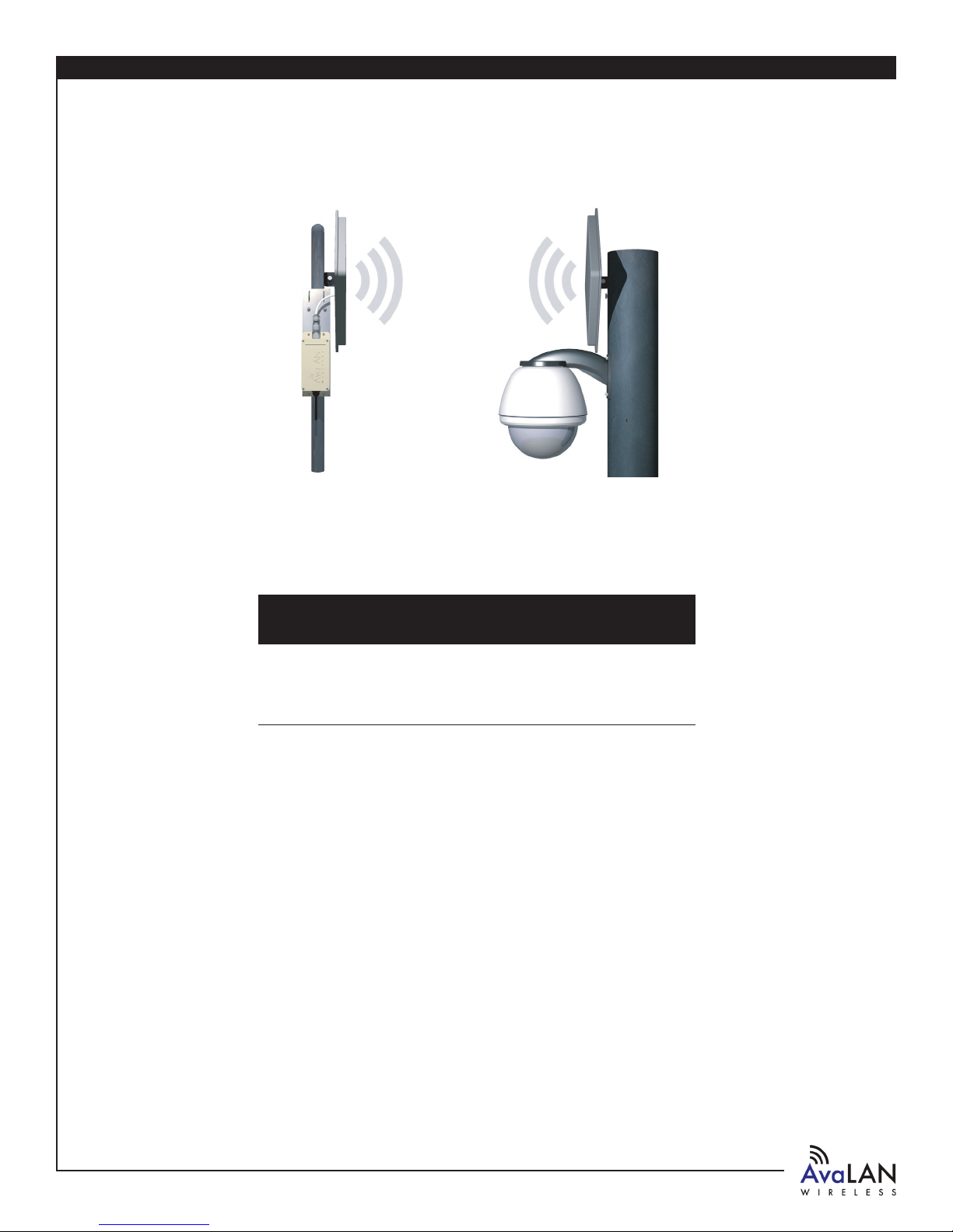
AW-D5800 Kit
Integrated 5.8 GHz wireless dome housing for PTZ network
cameras. Kit includes:
n
— (1) Videolarm (FDW75C2N) outdoor dome housing with
— heater/blower
n
— (1) AW5800x outdoor radio
n
— (2) 120 VAC to 24 VAC/40 Va transformers
n
— (2) AW5-5800 5dBi omni-directional antennae
n
— (1) 120 VAC to 12 VDC power adapter
n
— (1) Power over Ethernet injector
Shown with optional
AW23-5800 antennae
purchased separately
Or upgrade to optional AW23-5800 antennae
Initial setup
CAMERA
1) Set up your network camera while attached to a network. Please refer to the manufacturer’s instructions provided with the
camera.
2) Check that the video from the camera can be viewed on a networked PC.
3) To optimize the camera for use over a wireless link, please see the camera performance FAQ at www.avalanwireless.com/support.
DOME
1) Install the Videolarm FDW75C2N/AW-D5800 dome housing using the supplied 120 VAC to 24 VAC transformers. Please contact
Videolarm for installation support on the dome housing (www.videolarm.com; (800) 554-1124).
2) Mount the network camera within the dome housing according to Videolarm’s instructions.
3) Attach the antenna to the dome.
WIRELESS SETUP
1) Install the AW5800x.
2) Attach the antenna to the AW5800x (see Appendix B for polarization guide on Page 7).
3) Attach the white power injector to the end of the Ethernet cable.
4) Attach the 120 VAC to 12 VDC power supply to the white power injector.
5) Connect an Ethernet cable from the injector to the network (or directly to a PC).
6) The AvaLAN radios automatically select the best radio channel, encrypt the Ethernet data, and transport the data wirelessly to its
mate.
7) Use an Internet browser on a networked PC to view the video from the camera. Make sure the subnet/IP addresses of the PC and
the camera are compatible.
8) For radio/network troubleshooting, see Page 4.
Technical support :: (650) 384.0000
PAGE 2
www.avalanwireless.com
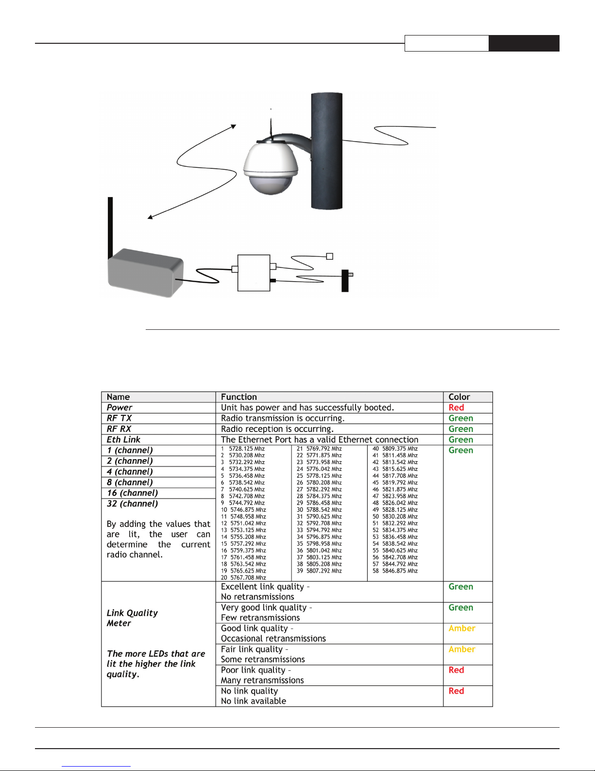
System diagram
AW-D5800User’s Manual
Ultra-long-range
digital Ethernet
5.8 GHz radio link
AW5800x mate
Power over Ethernet
injector (included)
9-48 VDC
24 VAC
Ethernet
RJ45 10BaseT
Power adapter
120 VAC to 12 VDC
(included)
Power adapter
2x 120 VAC to 24 VAC
(included)
LED display
The AW5800x mate has a 16 LED display that shows the status of the device. These LEDs can be viewed by removing the cover.
www.avalanwireless.com
PAGE 3
Technical support :: (650) 384.0000

AW-D5800 User’s Manual
Troubleshooting
See the online installation tutorial and FAQ at www.avalanwireless.com.
No Power LED
Check the power connections.
No Radio Link LED
The radio is looking for its matched partner. If both units are powered up and the Power LEDs are active, they may be too far away
to create the radio connection. Try other locations that may have a less obstructed path, or try reorienting the antennas. Direc-
tional antennae get their best range when they are oriented to point directly at each other with the antenna elements oriented in
the same plane (i.e. vertically or horizontally).
Radio LINK LED ON but Link Quality Indicator is low
The units may be too far away to create a good radio connection. Try other locations that may have a less obstructed path, or try
reorienting the antennas.
No Ethernet LINK LED
Check your network connections.
Installing multiple systems in close proximity
See the online installation tutorial and FAQ at www.avalanwireless.com.
Advanced settings
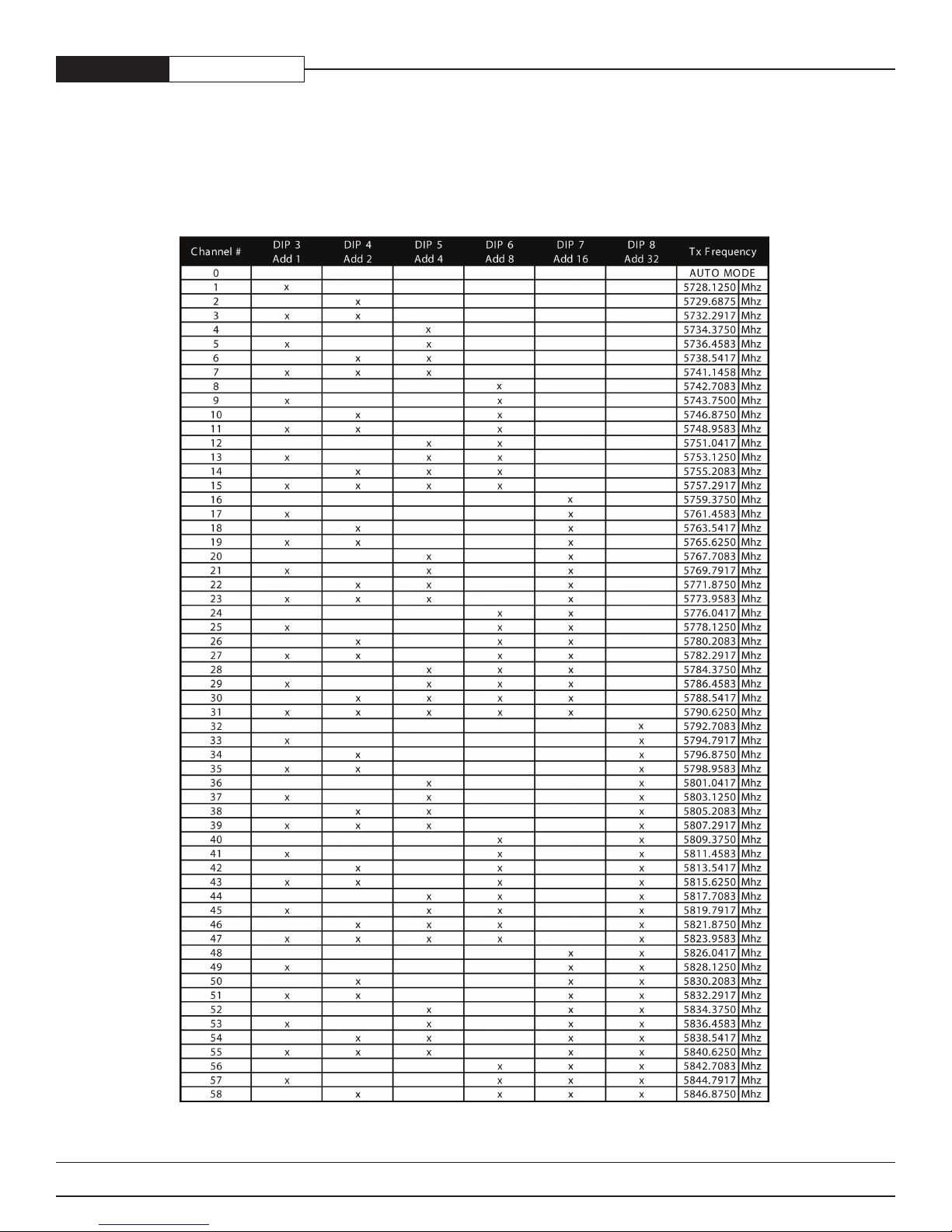
Automatic frequency selection mode (DIP switches — all OFF for automatic mode)
The AW5800x is designed to automatically select and continuously optimize the performance of its radio channel. The radio channel
is monitored to ensure it is providing low error rates necessary for successful radio transmission. In the event that the error rate
rises, the AW5800x will autonomously change to a new channel. There are 58 non-overlapping channels.
Manual frequency selection mode
This mode enables the user to restrict the operation of the AW5800x to a specic channel. This can be done by setting DIP switches
3-8 as shown in the table on Page 6.
Site survey mode (DIP switch 2 — default is OFF for normal operation)
In this mode the AW5800x can perform a site survey. With this mode activated the radios send and receive at 100 percent capacity
by transceiving self-generated simulated data. The installer can monitor the Link Quality display to assess channel quality while
optimizing antennae orientation. The installer can manually select each channel to evaluate performance and identify the best
channels for operation. By identifying channels with poor performance it is possible to identify possible interferers and use “manual
frequency selection mode” to avoid portions of the band or select a xed operating frequency.
NOTE: Ethernet trafc does not get transported while the radios are in this mode.
Power save mode (DIP switch 1 — default is OFF for normal LED display)
In this mode the display LEDs can be turned off for lower power applications (i.e. solar).
Technical support :: (650) 384.0000
PAGE 4
www.avalanwireless.com
Technical specications
CHARACTERISTIC SPECIFICATION / DESCRIPTION
RF transmission rate
Ethernet throughput
Output power
Receive sensitivity
Radio link budget
Line-of-sight range
Radio channels/bandwidth
Voltage range
Power consumption
Radio channels
Automatic frequency select
Manual frequency mode
Status LEDs
Error correction technique
Temperature range
Voltage range
1.563 Mb/s
935 Mb/s
+21 dBm (20 Watts EIRP used with 23 dBi antennae AW23-5800)
-98 dBm at 10e-4 BER (-121 dBm with 23 dBi antennae AW23-5800)
128 dB with 5 dBi antenna AW5-5800
164 dB with 23 dBi antennae AW23-5800
1 mile LOS with 5 dBi antenna AW5-5800
40 miles LOS with 23 dBi antennae AW23-5800
58 non-overlapping with 2.0833 MHz spacing and 1.75 MHz occupied bandwidth
AW-5800x receiver: 9-48 VDC (120 VAC to 12 VDC adapter included) / 24 VAC optional — AW-24V
AW-D5800: 24 VAC
AW-5800x: TX 1.8 W and RX 1 W over 9-48 VDC input voltage
AW-D5800: 55 W (including 20 W heater) maximum
58 non-overlapping
Yes — radio channel automatically selected and adaptively optimized
Ye s
Power, Ethernet Link, RF RX, RF TX, 6/Channel, and 6/Link Quality
Sub-block error detection and retransmission
AW-5800x: -40o C to 70o C (depends on temperature range of camera)
AW-D5800: -30o C to 50o C (depends on temperature range of camera)
Heater turns on at 10o C and off at 27o C
Blower turns on at 45o C and off at 27o C
Use with 9 VDC to 48 VDC POE systems with lines 4/5 positive, 7/8 ground
AW-D5800User’s Manual
Warranty
This product is warranted to the original purchaser for normal use for a period of 180 days from the date of purchase. If a defect
covered under this warranty occurs, AvaLAN will repair or replace the defective part, at its option, at no cost. This warranty does not
cover defects resulting from misuse or modication of the product.
www.avalanwireless.com
PAGE 5
Technical support :: (650) 384.0000
AW-D5800 User’s Manual
Appendix A — 5800 channel table
Manual frequency selection mode: This mode enables the user to restrict the operation of the AW5800x to a specic channel. This
can be done by setting DIP switches 3-8 as shown in the table below.
Technical support :: (650) 384.0000
PAGE 6
www.avalanwireless.com
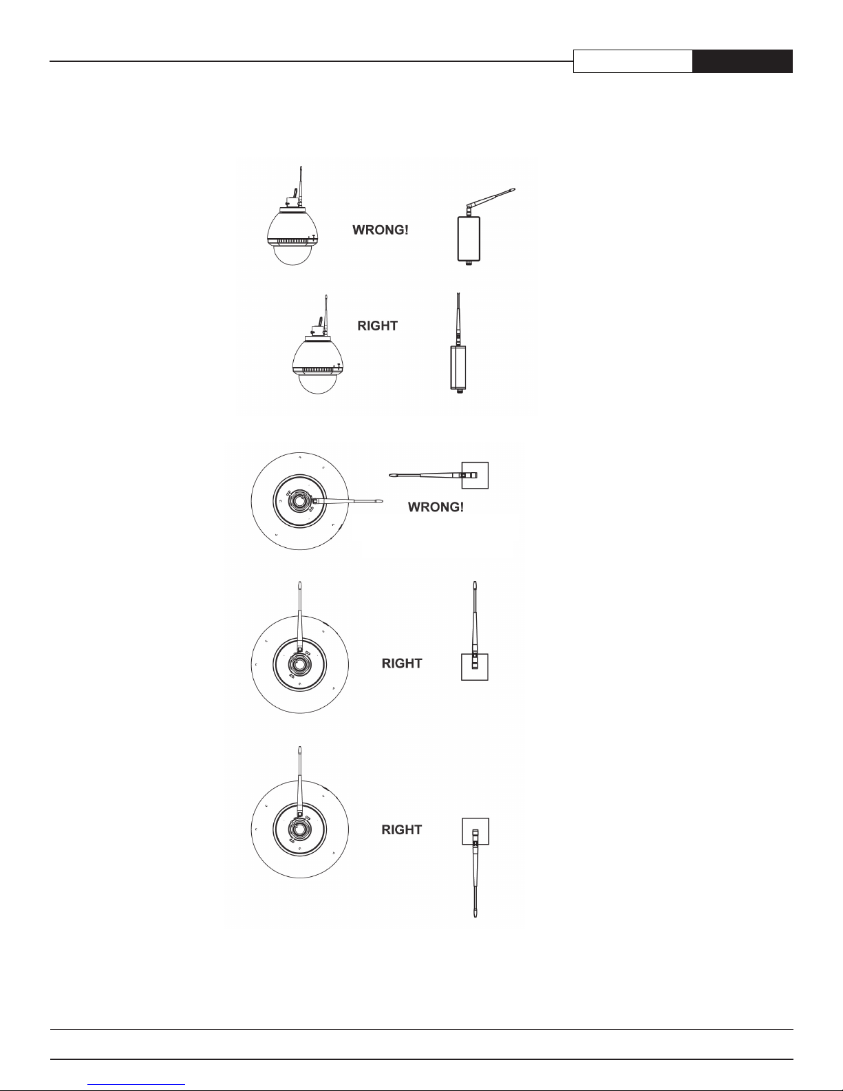
Appendix B — Antenna alignment guide
AW-D5800User’s Manual
Do not aim the omni-antennae
directly at each other
www.avalanwireless.com
PAGE 7
Technical support :: (650) 384.0000

©2004 — 2007 AvaLAN Wireless Systems Incorporated. All rights reserved. AvaLAN Wireless and the AvaLAN Wireless logo are registered trademarks of AvaLAN Wireless Systems
Incorporated. All other trademarks are property of their respective owners. AvaLAN Wireless makes no representations or warranties with respect to the accuracy, utility, or
completeness of the contents of this publication and reserves the right to make changes to specications and product descriptions at any time without notice. No license, express
or implied, by estoppel or otherwise, to any patents or other intellectual property rights is granted by this document. Particular uses or applications may invalidate some of the
specications and/or product descriptions contained herein. The customer is urged to perform its own engineering review before deciding on a particular application. AvaLAN
Wireless products are not designed for use in medical, life saving, or life sustaining applications. 07.07.2007
support@avalanwireless.com
Technical support :: (650) 384.0000
For advanced installation information visit
www.avalanwireless.com
 Loading...