

Page 1

USER’S
GUIDE
LSI21040
PCI to Dual Channel
Ultra160 SCSI
Host Adapter
Version 1.1
November 2000
®
S14043.B
Page 2
Electromagnetic Compatibility Notices
This device complies with Part 15 of the FCC Rules. Operation is subject to the following two conditions:
1. This device may not cause harmful interference, and
2. This device must accept any interference received, inc luding interference that may cause undesired operation.
This equipment has been tested and found to comply with the limits for a Class B digital device, pursuant to part 15
of the FCC Rules. These limits are designed to provide reasonable protection against harmful interference in a
residential installation. This equipment generates, uses, and can radiate radio frequency energy and, if not installed
and used in accordance with the instructions, may cause harmful interference to radio communications. However,
there is no guarantee that interference will not occur in a particular installation. If this equipment does cause har mful
interference to radio or television reception, which can be determined by turning the equipment off and on, the user
is encouraged to try to correct the interference by one or more of the following measures:
• Reorient or relocate the receiving antenna.
• Increase the separation between the equipment and the receiver.
• Connect the equipment into an outlet on a circuit different from that to which the receiver is connected.
• Consult the dealer or an experienced radio/TV technician for help.
Shielded cables for SCSI connection external to the cabinet are used in the compliance testing of this Product. LSI
Logic is notresponsible for anyradio or televisioninterference caused byunauthor ized modification of this equipment
or the substitution or attachment of connecting cables and equipment other than those specified by LSI Logic. The
correction of interferences caused by s uch unauthorized modification, substitution, or attachment will be the
responsibility of the us er.
The LSI Logic LSI21040 is tested to comply with FCC standards for home or office use.
This Class B digital apparatus meets all requirements of the Canadian Interference-Causing Equipment Regulations.
Cet appareil numérique de la classe B respecte toutes les exigences du Règlement sur le matériel brouilleur du
Canada.
This is a Class B product based on the standard of the Voluntary Control Council for Interference from Information
Technology Equipment (VCCI). If this is used near a radio or television receiver in a domestic environment, it may
cause radio interference. Install and use the equipment according to the instruction manual.
LSI Logic Corporation
North American Headquarters
Milpitas, CA
408.433.8000
ii
Page 3

This document contains proprietary information of LSI Logic Corporation. The
information contained herein is not to be used by or disclosed to third parties
without the express written permission of an officer of LSI Logic Corporation.
LSI Logic products are not intended for use in life-support appliances, devices,
or systems. Use of any LSI Logic product in such applications without written
consent of the appropriate LSI Logic officer is prohibited.
Document DB15-000148-02, Second Edition (November 2000).
This document describes the LSI Logic LSI21040 PCI to Dual Channel Ultra160
SCSI Host Adapter and will remain the official reference source for all
revisions/releases of this product until rescinded by an update.
To receive product literature, visit us at http://www.lsilogic.com.
LSI Logic Corporation reserves the right to make changes to any products herein
at any time without notice. LSI Logic does not assume any responsibility or
liability arising out of the application or use of any product described herein,
except as expressly agreed to in writing by LSI Logic; nor does the purchase or
use of a product from LSI Logic convey a license under any patent rights,
copyrights, trademark rights, or any other of the intellectual property rights of
LSI Logic or third parties.
Copyright © 2000 by LSI Logic Corporation. All rights reserved.
TRADEMARK ACKNOWLEDGMENT
The LSI Logic logo design, SDMS, SCRIPTS, SURElink, TolerANT, and LVDLink
are registeredtrademarks or trademarksof LSI Logic Corporation. Allo ther brand
and product names may be trademarks of their respective companies.
iii
Page 4

iv
Page 5

Audience
Organization
Preface
This book is the primary reference and user’s guide for the LSI Logic
LSI21040 PCI to Dual Channel Ultra160 SCSI Host Adapter. It contains
a complete functional description for the LSI21040 as well as complete
physical and electrical specifications.
This document assumes that you have some familiarity with SCSI
protocol and related support devices and will benefit persons installing
and using the LSI21040.
This document has the following chapters and appendix:
• Chapter 1, Using the LSI21040, defines the interfaces and
characteristics of the LSI21040.
• Chapter 2, Installing the LSI21040, provides both quick and detailed
installation instructions.
• Chapter 3, Specifying the Technical Characteristics, describes the
physical and operational environments of the LSI21040.
• Appendix A, Glossary of Terms and Abbreviations,provides
definitions of various terminology that is referenced throughout this
user’s guide.
Preface v
Page 6

Related Publications
PCI Storage Device Management System SDMS™ 4.0 User’s Guide,
Order Number S14007.A
SCSI SCRIPTS Processors Programming Guide,OrderNumber
S14044.A
LSI53C1010-33 PCI to Dual Channel Ultra3 SCSI Multifunction
Controller Technical Manual, Order Number S14025.C
Revision Record
Revision Date Remarks
1.0 5/00 Final version.
1.1 11/00 All product names changed from SYM to LSI.
vi Preface
Page 7

Contents
Chapter 1 Using the LSI21040
1.1 General Description 1-1
1.2 Features 1-2
1.2.1 PCI Interface 1-2
1.2.2 SCSI Interface 1-3
1.2.3 Board Characteristics 1-4
1.2.4 SCSI Bus Activity LED Connector 1-4
1.3 Benefits of Ultra160 SCSI 1-5
1.3.1 Double Transition (DT) Clocking 1-5
1.3.2 Cyclic Redundancy Check (CRC) 1-5
1.3.3 Domain Validation 1-5
1.3.4 Asynchronous Information Protection (AIP) 1-6
1.4 Benefits of LVD Link Technology 1-6
1.5 Benefits of TolerANT
1.6 Benefits of SURElink (Extended Domain Validation) 1-7
®
Technology 1-6
Chapter 2 Installing the LSI21040
2.1 Quick Installation Procedure 2-1
2.2 Detailed Installation Procedure 2-2
2.2.1 Before You Start 2-2
2.2.2 Inserting the Host Adapter 2-2
2.2.3 Connecting the SCSI Peripherals 2-6
2.2.4 Making Internal SCSI Bus Connections 2-9
2.2.5 Making External SCSI Bus Connections 2-14
2.2.6 SCSI Bus Termination 2-17
2.2.7 Setting SCSI IDs 2-23
2.3 Completing the Installation 2-25
2.4 Troubleshooting 2-26
Contents vii
Page 8

Chapter 3 Specifying the Technical Characteristics
3.1 Physical Environment 3-1
3.1.1 Physical Characteristics 3-1
3.1.2 Electrical Characteristics 3-2
3.1.3 Thermal, Atmospheric Characteristics 3-3
3.1.4 Electromagnetic Compliance 3-3
3.1.5 Safety Characteristics 3-3
3.2 Operational Environment 3-4
3.2.1 The PCI Interface 3-4
3.2.2 The SCSI Interface 3-7
3.2.3 SCSI Activity LED Interface 3-10
3.3 Subsystem and Subsystem Vendor ID 3-10
Appendix A Glossary of Terms and Abbreviations
Index
Customer Feedback
Figures
2.1 Hardware Connections for the LSI21040 2-4
2.2 Inserting the Host Adapter 2-5
2.3 SCSI Cables 2-8
2.4 Internal SCSI Ribbon Cable to Host Adapter Connection 2-9
2.5 Internal SCSI Ribbon Cable to Internal SCSI Device
Connection 2-10
2.6 Connecting Additional Internal SCSI Devices 2-11
2.7 Multiple Internal SCSI Devices Chained Together 2-12
2.8 SCSI LED Connector 2-13
2.9 External Cable to Host Adapter 2-14
2.10 External SCSI Device Cable 2-15
2.11 Multiple External SCSI Devices Chained Together 2-16
2.12 Internal SCSI Device Termination 2-19
viii Contents
Page 9

Tables
2.13 External SCSI Device Termination 2-20
2.14 Internal and External SCSI Device Termination 2-22
3.1 LSI21040 Mechanical Drawing 3-2
2.1 SCSI Bus Widths and Speeds 2-6
2.2 SCSI Bus Lengths 2-7
2.3 SCSI ID Record 2-24
3.1 PCI Connector J1 (F ront) 3-5
3.2 PCI Connector J1 (Back) 3-6
3.7 LED Connector J6 3-10
3.8 Subsystem and Subsystem Vendor ID 3-10
Contents ix
Page 10

xContents
Page 11

3.75 pc 10.25 pc 11.25 pc 38.25 pc
34.5 pc
4.333 pc
Chapter 1
Using the LSI21040
12 pc
12.938 pc
This chapter describes the LSI21040 PCI to Ultra160 SCSI Dual Channel
Host Adapter interface to PCI computer systems and includes these
topics:
• Section 1.1, “General Description,” page 1-1
• Section 1.2, “Features,” page 1-2
• Section 1.3, “Benefits of Ultra160 SCSI,” page 1-5
• Section 1.4, “Benefits of LVD Link Technology,” page 1-6
• Section 1.5, “Benefits of TolerANT
®
Technology,” page 1-6
13.851 pc
34.732 pc
• Section 1.6, “Benefits of SURElink (Extended Domain Validation),”
page 1-7
1.1 General Description
The LSI21040 provides an Ultra160 SCSI interface to PCI computer
systems. It is referred to as the LSI21040 throughout this guide.Installing
this adapter in your PCI system allows connection of up to 15 SCSI
devices per channel. The LSI21040 uses the LSI53C1010 PCI to
Ultra160 Multifunction Controller chip.
The dual channel LSI21040 provides 16-bit Low Voltage Differential
(LVD) and Single-Ended (SE) SCSI solutions for your computer, using
only one PCI slot. This board supports legacy Fast SCSI, Ultra SCSI,
Ultra2 SCSI, and the newest Ultra160 SCSI devices.
Channel A supports SE and LVD modes of operation. Channel B
supports only the SE mode.
The Storage Device Management System (SDMS™) software operates
the board. You may also use SCSI software provided by other vendors
48.583 pc
LSI21040 PCI to Dual Channel Ultra160 SCSI Host Adapter 1-1
52.5 pc
Page 12

3.75 pc 10.25 pc 11.25 pc 38.25 pc
34.5 pc
that works with the LSI53C1010. The flash memory device on the board
4.333 pc
can incorporate the BIOS support for this host adapter. The LSI21040
has a serial EEPROM device for storing your SCSI bus configuration.
The LSI53C1010 also contains a SCSI SCRIPTS™ processor that
permits both DMA and SCSI commands to be fetched from host memory
or internal SCRIPTS RAM. Algorithms written in SCSI SCRIPTS control
the actions of the SCSI and DMA cores. The SCRIPTS processor
executes complex SCSI bus sequences independently of the host CPU.
For more information on the SCSI SCRIPTS Instruction Set used to write
these algorithms, refer to the SCSI SCRIPTS Processors Programming
Guide.
The PCI Storage Device Management System SDMS 4.0 User’s Guide
and this user’s guide contain a complete library of product information
and installation instructions. With this information, the full benefits of your
LSI21040 are available to you.
1.2 Features
44.25 pc
This section provides an overview of the PCI Interface,theSCSI
Interface, and Board Characteristics for the LSI21040.
1.2.1 PCI Interface
PCI interfaces I/O components to the processor and memory
subsystems in equipment ranging from PCs to servers. The PCI interface
operates as a 64-bit DMA bus master capable of 64-bit addressing. The
LSI53C1010 contains the PCI functionality for the LSI21040.
The PCI interface includes these features:
• Complies with PCI 2.2 specification
• Complies with PCI Bus Power Management Specification Rev 1.1
• Complies with PC99
• Supports up to 64-bit/33 MHz PCI interface for 264 Mbytes/s
bandwidth that:
– Supports 64-bit DMA bus mastership with 64-bit addressing
– Operates at 33 MHz
48.583 pc
1-2 Using the LSI21040
52.5 pc
Page 13

3.75 pc 10.25 pc 11.25 pc 38.25 pc
34.5 pc
– Supports dual address cycle generation for all SCRIPTS
– Presents a single electrical load to the PCI Bus (True PCI
Multifunction Device)
• Bursts 2 to 128 Dwords across the PCI bus
• Supports 32-bit or 64-bit word data bursts with variable burst lengths
• Supports the PCI Cache Line Size register
• Prefetches up to 8 Dwords of SCRIPTS instructions
• Supports PCI Write and Invalidate, Read Line, and Read Multiple
commands
• Bursts SCRIPTS opcode fetches across the PCI bus
• Supports universal 3.3 V and 5 V PCI signaling environment
1.2.2 SCSI Interface
The SCSI interface on the LSI21040 operates as an 8-bit or 16-bit
interface. It supports 8-bit or 16-bit, synchronous and asynchronous, LVD
or SE, Fast, Ultra, Ultra2, and Ultra160 SCSI protocols in various
44.25 pc
combinations.
4.333 pc
The LSI53C1010 contains the SCSI functionality for the LSI21040. This
chip is a PCI to Ultra160 SCSI Controller with LVD Link™ Universal
Transceivers. It connects directly to the SCSI bus and generates signal
timing and bus protocol in compliance with SCSI standards.
The SCSI interface includes these features:
• Performs wide, Ultra160 SCSI synchronous data transfers as fast as
160 Mbytes/s using Double Transition (DT) clocking for Channel A
• Performs wide, Ultra SCSI SE synchronous transfers as fast as
40 Mbytes/s for Channel B
• Enables LVD or SE termination on Channel A automatically
• Enables SE termination on Channel B automatically
• Contains internal 68-pin high density connectors for Channel A and
Channel B
• Contains internal ribbon connector 50-pin for Channel B
• Contains external connector 68-pin high density for Channel A
Features 1-3
48.583 pc
52.5 pc
Page 14

3.75 pc 10.25 pc 11.25 pc 38.25 pc
34.5 pc
• Provides SCSI termination power (TERMPWR) source with
autoresetting circuit protection device
4.333 pc
• Includes 8 Kbytes internal RAM f or SCRIPTS instruction storage for
each channel
• Supports SCSI Plug and Play
• Supports variable block size and scatter/gather data transfers
• Performs complex bus sequences without interrupts, including
restore data pointers
• Contains a serial EEPROM for user configuration utility
• Provides SCSI bus activity LED connector for each channel on one
connector
1.2.3 Board Characteristics
The LSI21040 characteristics are:
• PCI board dimensions: 152.4 x 88.90 mm (6.875 x 3.99 inches)
44.25 pc
• PCI Universal 64-bit card edge connector
• One high density 68-pin external connector
• Two high density 68-pin internal connectors
• One 50-pin internal ribbon connector
• SCSI Bus Activity LED connector
In Chapter 3, “Specifying the Technical Characteristics,” Figure 3.1
illustrates the mechanical drawing for this host adapter board.
1.2.4 SCSI Bus Activity LED Connector
A SCSI Bus Activity LED connector indicates the status of the SCSI bus
when an LED is attached. This LED lights when the SCSI bus is
transferring information.
48.583 pc
1-4 Using the LSI21040
52.5 pc
Page 15

3.75 pc 10.25 pc 11.25 pc 38.25 pc
34.5 pc
4.333 pc
1.3 Benefits of Ultra160 SCSI
Ultra160 SCSI delivers data up to two times faster than Ultra2 SCSI.
Ultra160 SCSI is a subset of the SCSI Parallel Interface-3 (SPI-3) draft
standard that allows faster synchronous SCSI data transf er rates than
Ultra2 SCSI. When enabled, Ultra160 SCSI performs 80 megatransfers
per second resulting in approximately double the synchronous data
transfer rates of Ultra2 SCSI. The LSI53C1010 performs 16-bit, Ultra160
SCSI synchronous data transfers as fast as 160 Mbytes/s. This
advantage is most noticeable in heavily loaded systems or large block
size applications, such as video on-demand and image processing.
1.3.1 Double Transition (DT) Clocking
Ultra160 SCSI includes DT clocking in order to double data transfer
speeds without increasing the clock rate. As a result, data is clocked on
both rising and falling edges of the Request and Acknowledge signals.
44.25 pc
1.3.2 Cyclic Redundancy Check (CRC)
Ultra160 SCSI includes CRC to provide data bus protection. CRC offers
higher levels of data reliability by ensuring complete integrity of
transferred data. CRC is a 32-bit scheme, referred to as CRC-32. CRC
is guaranteed to detect all single bit errors, all double bit errors, or any
combination of errors within a single 32-bit range.
1.3.3 Domain Validation
Ultra160 SCSI also includes Domain Validation to provide basic integrity
checking. Domain Validation is a procedure that allows a host computer
and target SCSI peripheral to negotiate and find the optimal transfer
speed. This procedure improves overall reliability of the system.
SURElink™ extends this feature by providing three levels of integrity
checking. Refer to Section 1.6, “Benefits of SURElink (Extended Domain
Validation),” on page 1-7 for more detailed information.
48.583 pc
Benefits of Ultra160 SCSI 1-5
52.5 pc
Page 16

3.75 pc 10.25 pc 11.25 pc 38.25 pc
34.5 pc
1.3.4 Asynchronous Information Protection (AIP)
4.333 pc
The LSI53C1010 supports AIP to protect all non-data phases, including
command, status, and messages. CRC, along with AIP, provides end-toend protection of the SCSI I/O.
1.4 Benefits of LVD Link Technology
To support greater device connectivity and a longer SCSI cable, the
LSI21040 features LVD Link technology, the LSI Logic implementation of
Universal LVD SCSI. LVD Link transceivers provide the inherent reliability
of differential SCSI, and a long-term migration path to faster SCSI
transfer rates.
The LVD Link transceivers reduce the power needed to drive the SCSI
bus, so that the I/O drivers can be integrated directly into the chip.
LVD Link technology lowers the amplitude of noise reflections and allows
higher transmission frequencies.
44.25 pc
The LVD Link transceivers operate in LVD and SE modes. They also
allow the chip to detect a High Voltage Differential (HVD) signal when the
chip is mistakenly connected to external HVD transceivers. When
connected, the LSI53C1010 automatically detects signal type, based on
the voltage detected. It automatically switches to the SE or LVD mode,
as appropriate.
Important:
All bus devices must be LVD or SE. If a HVD device is
detected, the board puts the SCSI bus in the high
impedance state and shuts down.
1.5 Benefits of TolerANT®Technology
The LSI53C1010 features TolerANT technology, which includes active
negation on the SCSI drivers and input signal filtering on the SCSI
receivers. Active negation causes the SCSI Request, Acknowledge,
Data, and Parity signals to be actively driven HIGH rather than passively
pulled up by terminators.
48.583 pc
1-6 Using the LSI21040
52.5 pc
Page 17

3.75 pc 10.25 pc 11.25 pc 38.25 pc
34.5 pc
TolerANT receiver technology improves data integrity in unreliable
4.333 pc
cabling environments where other devices would be subject to data
corruption. TolerANT receivers filter the SCSI bus signals to eliminate
unwanted transitions, without the long signal delay associated with
RC-type input filters. This improved driver and receiver technology helps
eliminate double clocking of data, which is the single biggest reliability
issue with SCSI operations. TolerANT input signal filtering is a built-in
feature of the LSI53C1010 and all LSI Logic Fast SCSI, Ultra SCSI,
Ultra2 SCSI, and Ultra160 SCSI devices.
The benefits of TolerANT technology include increased noise immunity
when the signal transitions to HIGH, better performance due to balanced
duty cycles, and improved fast SCSI transfer rates. In addition, TolerANT
SCSIdevicesdonotcauseglitchesontheSCSIbusatpower-upor
power-down. This technology protects other devices on the bus from data
corruption. When it is used with the LVD Link transceivers, TolerANT
technology provides excellent signal quality and data reliability in real
world cabling environments. TolerANT technologyis compatible with both
the Alternative One and Alternative Two termination schemes proposed
by the American National Standards Institute.
44.25 pc
1.6 Benefits of SURElink (Extended Domain Validation)
SURElink represents the very latest SCSI interconnect management
solution. It ensures robust and low risk Ultra160 SCSI implementations
by extending the Domain Validation guidelines documented in the ANSI
T10 SPI-3 specifications. Domain Validation verifies that the system is
capable of transferring data at Ultra160 speeds, allowing it to renegotiate
to lower speed and bus width if necessary.
SURElink is the software control for the manageability enhancements in
the LSI53C1010. Fully integrated in the SDMS software solution,
SURElink provides Domain Validation at boot time as well as throughout
system operation. SURElink extends to the Distributed Management
Interface (DMI) based System Management components of SDMS,
providing the network administrator remote management capability.
SURElink Domain Validation provides three levels of integrity checking:
Basic (lev el 1), Enhanced (level 2), and Margined (level 3). The basic
check consists of an inquiry command to detect gross problems. The
48.583 pc
Benefits of SURElink (Extended Domain Validation) 1-7
52.5 pc
Page 18

3.75 pc 10.25 pc 11.25 pc 38.25 pc
34.5 pc
enhanced check sends a known data pattern using the Read and Write
4.333 pc
Buffer commands to detect additional problems. The margined check
verifies that the physical parameters have some degree of margin.
By varying LVD drive strength and REQ/ACK timing characteristics,
level 3 verifies that no errors occur on the transfers. These altered
signals are only used during the diagnostic check and not during normal
system operation. Should errors occur with a ny of these checks, the
system can drop back to a lower transmission speed, on a per-target
basis, to ensure robust system operation.
44.25 pc
48.583 pc
1-8 Using the LSI21040
52.5 pc
Page 19

3.75 pc 10.25 pc 11.25 pc 38.25 pc
34.5 pc
4.333 pc
Chapter 2
Installing the LSI21040
12 pc
12.938 pc
This chapter provides instructions on how to install the LSI21040 and
includes these topics:
• Section 2.1, “Quick Installation Procedure,” page 2-1
• Section 2.2, “Detailed Installation Procedure,” page 2-2
• Section 2.3, “Completing the Installation,” page 2-25
• Section 2.4, “Troubleshooting,” page 2-26
13.851 pc
34.732 pc
2.1 Quick Installation Procedure
This section provides an overview of the installation procedure. If you are
an experienced computer user with prior host adapter installation and
SCSI bus setup experience, this section may sufficiently describe the
procedure for you. If you prefer a more detailed guidance for installing
the LSI21040, proceed to Section 2.2, “Detailed Installation Procedure.”
For safe and proper installation, check the user’s manual supplied with
your computer and perform the following steps.
Step 1. Ground yourself before removing this host adapter board.
Step 2. Remove the LSI21040 from the packing and check that it is not
damaged.
Figure 2.1 illustrates an example of this host adapter board.
Also refer to Figure 3.1 to see a more detailed drawing of this
board.
Step 3. Open your PC cabinet and select an appropriate open PCI slot.
Step 4. Insert the host adapter board.
Step 5. Connect the internal and external SCSI peripherals.
48.583 pc
LSI21040 PCI to Dual Channel Ultra160 SCSI Host Adapter 2-1
52.5 pc
Page 20

3.75 pc 10.25 pc 11.25 pc 38.25 pc
34.5 pc
Step 6. Terminate the SCSI bus.
The SCSI bus requires proper termination and no duplicate
SCSI IDs.
Step 7. Set the peripheral SCSI IDs.
Step 8. Make any configuration changes.
Step 9. Close your PC cabinet cover.
Step 10. Make all external SCSI bus connections.
Step 11. Refer to the PCI Storage Device Management System SDMS
4.0 User’s Guide (or the guide for the software you will use) to
load the driver software for your particular operating system.
2.2 Detailed Installation Procedure
This section provides step-by-step instructions for installing the
LSI21040, and connecting it to your SCSI peripherals. If you are
experienced in these tasks, you may prefer to use Section 2.1, “Quick
Installation Procedure.”
44.25 pc
4.333 pc
2.2.1 Before You Start
Before starting, look through the following task list to get an overall idea
of the steps you will be performing. If you are not confident you can
perform the tasks as described here, LSI Logic recommends getting
assistance.
The SCSI host adapter acts on your computer’s behalf as the host to
your suite of SCSI peripherals. Each chain of SCSI peripheral devices
and their host adapter work together. They are referred to as a SCSI bus.
Each SCSI host adapter that you install can act as host for up to
15 peripheral devices, not including the adapter itself. Follow the detailed
instructions in the next section to successfully install your host adapter
board.
2.2.2 Inserting the Host Adapter
For safe and proper installation, you will need the user’s manual supplied
with your computer. Perform the following steps to install the LSI21040.
48.583 pc
2-2 Installing the LSI21040
52.5 pc
Page 21

3.75 pc 10.25 pc 11.25 pc 38.25 pc
34.5 pc
Step 1. Ground yourself before removing this host adapter board.
4.333 pc
Step 2. Remove the LSI21040 from the packing and check that it is not
damaged.
Figure 2.1 illustrates an example of this host adapter board.
Also refer to Figure 3.1 to see a more detailed drawing of this
board.
Step 3. Switch off the computer and unplug power cords for all
components in your system.
Step 4. Remove the cover from your computer per the instructions in
the user’s manual for your system to access the PCI slots.
44.25 pc
Caution:
Ground yourself by touching a metal surface before
removing the cabinet top . Static charges on your body can
damage electronic components. Handle plug-in boards by
the edge; do not touch board components or gold
connector contacts. The use of a static ground strap is
recommended.
Step 5. Locate the slots for PCI plug-in board installation.
Refer to the user’s manual for your computer to confirm the
location of the PCI slots.
The LSI21040 requires a 32-bit or 64-bit PCI slot that allows
bus master operation. If a 32-bit PCI slot is used, bits [31:0] of
the J1 connector are inserted while bits [63:32] remain
uninserted. See Figure 2.2.
Note:
For the LSI21040 to function as a 64-bit device, it must be
inserted in a 64-bit PCI slot. If the LSI21040 is inserted in
a 32-bit PCI slot, it will function as a 32-bit device.
Step 6. Remove the blank bracket panel on the back of the computer
aligned with the PCI slot you intend to use. Save the bracket
screw.
Detailed Installation Procedure 2-3
48.583 pc
52.5 pc
Page 22
3.75 pc 10.25 pc 11.25 pc 38.25 pc
34.5 pc
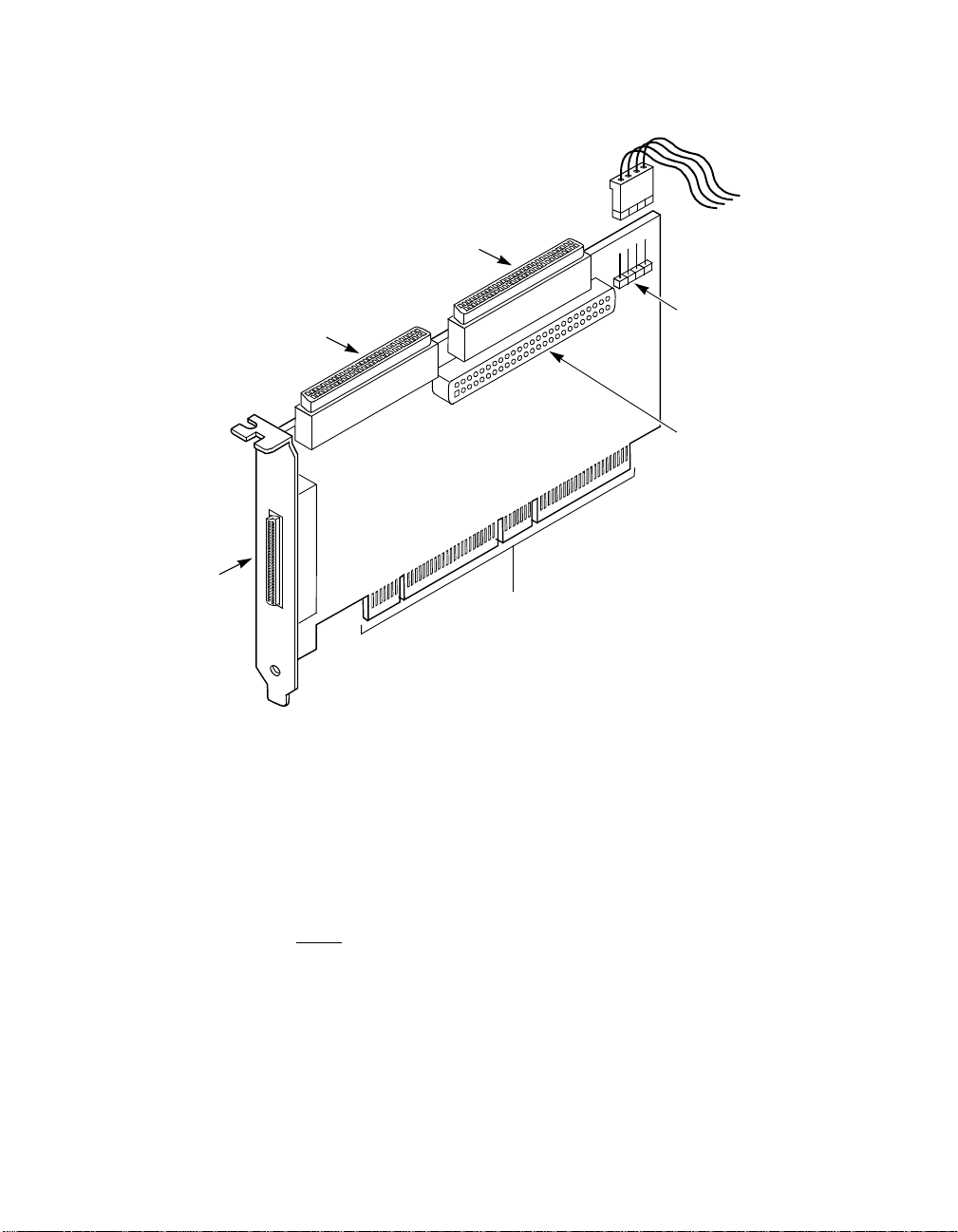
Figure 2.1 Hardware Connections for the LSI21040
Channel B 68-Pin
Internal High
Density SCSI
Connector J2
4.333 pc
44.25 pc
68-Pin External
High Density SCSI
Connector J3
Channel A 68-Pin
Internal High
Density SCSI
Connector J4
LSI21040 PCI Bus
Edge Connector J1
Channel A and B
Busy LED
Connector J6
Channel B 50-Pin
Low Density SCSI
Connector J5
Step 7. Carefully insert edge connector J1 (see Figure 2.1) of the host
adapter into the PCI slot.
Make sure the edge connector is properly aligned before
pressing the board into place as shown in Figure 2.2.The
bracket around connector J3 should fit where you removed the
blank panel.
Note:
You may notice that the components on a PCI host adapter
face the opposite way from non-PCI adapter boards you
have in your system. This orientation is correct. The board
is keyed and will only go in one way .
2-4 Installing the LSI21040
48.583 pc
52.5 pc
Page 23

3.75 pc 10.25 pc 11.25 pc 38.25 pc
34.5 pc
Figure 2.2 Inserting the Host Adapter
Bracket Screw
4.333 pc
44.25 pc
32-bit slot
64-bit slots
Step 8. Secure the board with the bracket screw (see Figure 2.2)before
making the internal and external SCSI bus connections.
48.583 pc
Detailed Installation Procedure 2-5
52.5 pc
Page 24

3.75 pc 10.25 pc 11.25 pc 38.25 pc
34.5 pc
2.2.3 Connecting the SCSI Peripherals
4.333 pc
All internal SCSI bus connections to the LSI21040 are made with an
unshielded 68 conductor Ultra SCSI TPE ribbon cable (see Figure 2.3)
and also a 50-pin ribbon cable. The lead connected to pin 1 on the cable
is marked with a colored stripe. The connectors on this cable may also
be keyed to ensure proper pin connection.
All external SCSI bus connections to the LSI21040 are made with high
quality shielded 68 conductor cables (see Figure 2.3). The connectors on
this cable are always keyed to ensure proper pin connection.
44.25 pc
Note:
All the cables shown in Figure 2.3 are included in the
LSI Logic Adapter Board Kit for the LSI21040.
Table 2.1 provides a list of the SCSI bus width and maximum data
transfer rate for various SCSI definitions.
Table 2.1 SCSI Bus Widths and Speeds
SCSI Bus Speed
STA Terms
SCSI-1 8 5
Fast SCSI 8 10
Fast Wide SCSI 16 20
Ultra SCSI 8 20
Wide Ultra SCSI 16 40
Wide Ultra2 SCSI 16 80
Ultra160 SCSI 16 160
SCSI Bus
Width, Bits
Maximum Data Rate,
Mbytes/s
You can connect up to eight SCSI, Fast SCSI, and Ultra SCSI devices
on an SE Ultra SCSI bus only if they are evenly spaced on a 1.5-meter
Ultra SCSI cable (0.19 m between devices).
2-6 Installing the LSI21040
48.583 pc
52.5 pc
Page 25

3.75 pc 10.25 pc 11.25 pc 38.25 pc
34.5 pc
You can connect up to four devices if they are evenly spaced on a
4.333 pc
3-meter Ultra SCSI cable (0.75 m between devices). Your SE SCSI bus
should not exceed 3 meters (total internal and external cable lengths),
even with fewer than four devices.
For LVD applications, you can connect up to 16 devices including the
host adapter if they are evenly spaced on a 12-meter Ultra SCSI cable
(0.19 m minimum between devices). Table 2.2 provides a list of the
maximum bus lengths and the maximum number of devices for various
SCSI definitions.
Table 2.2 SCSI Bus Lengths
44.25 pc
Maximum Bus Length, Meters
1
Maximum #
SE Differential LVD
of Devices
SCSI-1 6 25 12 8
Fast SCSI 3 25 12 8
Fast Wide SCSI 3 25 12 16
Ultra SCSI 1.5
Ultra SCSI 3
2
2
25 12 8
––4
Wide Ultra SCSI – 25 12 16
Wide Ultra SCSI 1.5 – – 8
Wide Ultra SCSI 3 – – 4
Ultra2 SCSI Note
Wide Ultra2 SCSI Note
Ultra160 SCSI Note
3
3
3
Note
Note
Note
3
3
3
12 8
12 16
12 16
1. This parameter may be exceeded in point-to-point and engineered
applications.
2. Additional spacing rules apply.
3. SE and high power differential are not defined at Ultra2 or Ultra160 speeds.
Detailed Installation Procedure 2-7
48.583 pc
52.5 pc
Page 26

3.75 pc 10.25 pc 11.25 pc 38.25 pc
34.5 pc
Figure 2.3 SCSI Cables
4.333 pc
44.25 pc
SCSI Cable for Internal Connections
68-Pin High Density
and/or
50-Pin Low Density
SCSI Cable for External Conn ections
68-Pin High Density
2-8 Installing the LSI21040
48.583 pc
52.5 pc
Page 27

3.75 pc 10.25 pc 11.25 pc 38.25 pc
34.5 pc
2.2.4 Making Internal SCSI Bus Connections
4.333 pc
This section provides step-by-step instructions about making internal
SCSI bus connections.
Step 1. Plug one end of the 68-pin internal SCSI ribbon cable into
connector J4 or J2. Figure 2.4 illustrates an example for this
step.
44.25 pc
Important
: You must match pin 1 on this and all subsequent
connections.
Figure 2.4 Internal SCSI Ribbon Cable to Host Adapter
Connection
J2
J4
Detailed Installation Procedure 2-9
48.583 pc
52.5 pc
Page 28

3.75 pc 10.25 pc 11.25 pc 38.25 pc
34.5 pc
Step 2. If you have only two internal devices to connect, plug the other
4.333 pc
end of the internal SCSI ribbon cable into the SCSI connector
on your internal SCSI device. Figure 2.5 illustrates an example
of this connection.
44.25 pc
Note:
For nonterminated internal SCSI devices, a terminated
cable will be required. This connector must be on the end
of the SCSI cable.
Figure 2.5 Internal SCSI Ribbon Cable to Internal SCSI Device
Connection
2-10 Installing the LSI21040
48.583 pc
52.5 pc
Page 29

3.75 pc 10.25 pc 11.25 pc 38.25 pc
34.5 pc
If you have more than one internal device to connect, use an internal
4.333 pc
SCSI ribbon cable with the required number of connectors attached
along its length and proceed to the next step. Figure 2.6 illustrates t his
type of a connection. If you have only one internal device, proceed to
Step 4 on page 2-13.
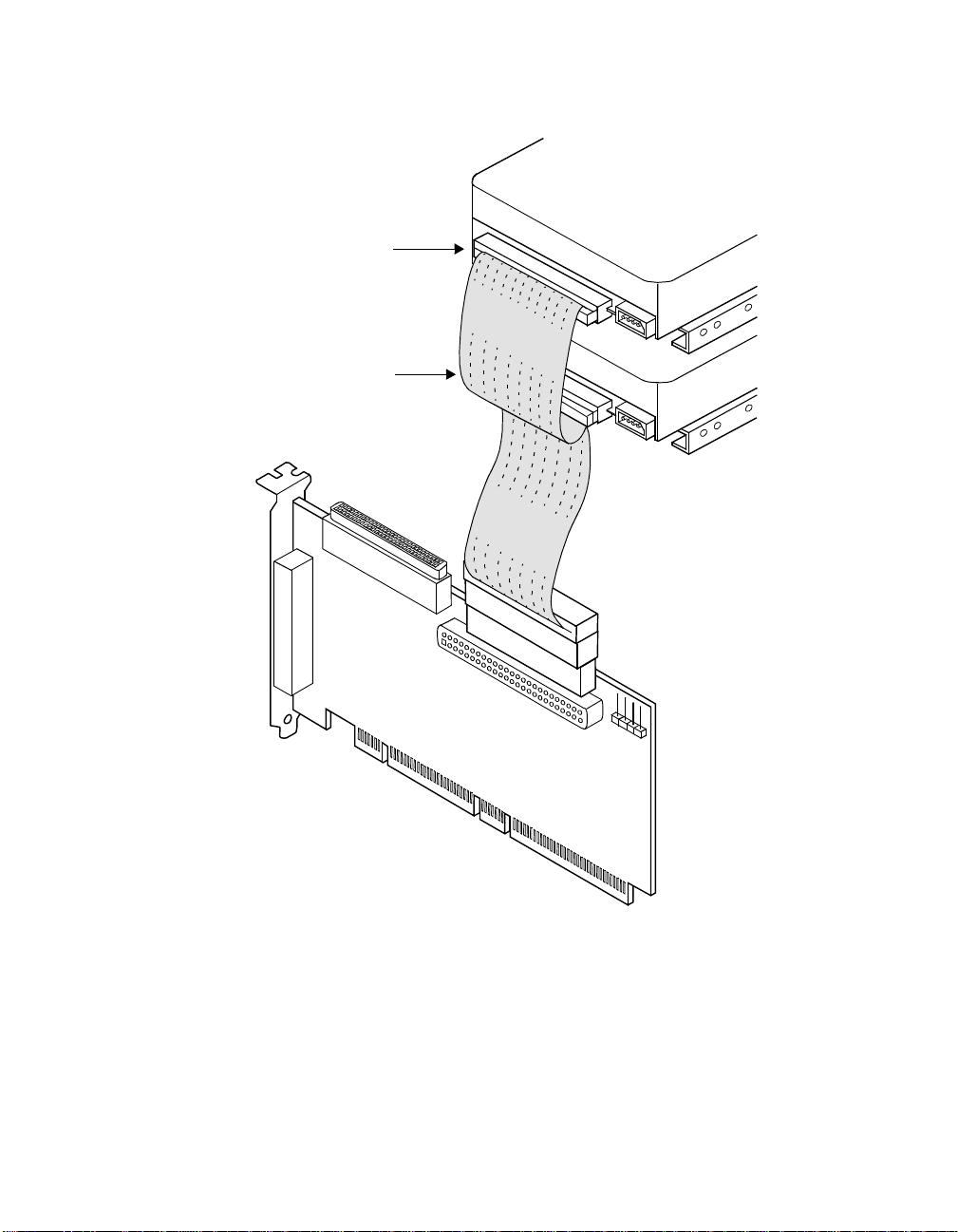
Step 3. Plug the cable into each additional device as needed.
Figure 2.7 provides an example of this type of chained
connection. Make sure to match pin 1 on all connections.
Figure 2.6 Connecting Additional Internal SCSI Devices
44.25 pc
48.583 pc
Detailed Installation Procedure 2-11
52.5 pc
Page 30
3.75 pc 10.25 pc 11.25 pc 38.25 pc
34.5 pc
Figure 2.7 Multiple Internal SCSI Devices Chained Together
4.333 pc
Termination
Enabled
Termination
Disabled
44.25 pc
48.583 pc
2-12 Installing the LSI21040
52.5 pc
Page 31

3.75 pc 10.25 pc 11.25 pc 38.25 pc
34.5 pc
Most PC cabinets are designed with a front panel LED.
4.333 pc
Step 4. Connect the LED cable to connector J6 on the host adapter, as
shown in Figure 2.8.
When properly connected, the front panel LED lights when
there is activity on the SCSI bus.
Connector J6 is not keyed. The orientation of the LED cable
should not matter as long as all four pins are connected. If the
LED does not light during SCSI bus activity from this host
adapter, you may have to rotate the LED cable connector 180
°
on J6.
Figure 2.8 SCSI LED Connector
44.25 pc
LED
Cable
LED Connector J6
Left two pins are for Channel A
Right two pinsare for Channel B
Some LED cables have only two wires. In this case, place the
connector on one end or the other of J6. If the LED does not
light when there is SCSI activity, put the connector on the other
half of J6.
48.583 pc
Detailed Installation Procedure 2-13
52.5 pc
Page 32

3.75 pc 10.25 pc 11.25 pc 38.25 pc
34.5 pc
2.2.5 Making External SCSI Bus Connections
4.333 pc
This section provides step-by-step instructions about making external
SCSI bus connections. To connect external SCSI devices to the
LSI21040, follow these steps:
Step 1. Plug the 68-pin HD connector on one end of a shielded external
SCSI cable into the host adapter connector J3. (Figure 2.3
provides examples of SCSI cables to use.)
This connector is in the bracket attached to the back panel of
your computer. Figure 2.9 shows how this connection is made.
Figure 2.9 External Cable to Host Adapter
44.25 pc
48.583 pc
2-14 Installing the LSI21040
52.5 pc
Page 33

3.75 pc 10.25 pc 11.25 pc 38.25 pc
34.5 pc
Step 2. Plug the 68-pin connector on the other end of the shielded
4.333 pc
external SCSI cable into the SCSI connector on your external
SCSI device. Figure 2.10 illustrates an example of this
connection.
Figure 2.10 External SCSI Device Cable
44.25 pc
If this is the only external SCSI device on your system, proceed to
Section 2.2.6, “SCSI Bus Termination,” on page 2-17 for termination
instructions. If you have multiple SCSI devices, proceed to the next page.
48.583 pc
Detailed Installation Procedure 2-15
52.5 pc
Page 34

3.75 pc 10.25 pc 11.25 pc 38.25 pc
34.5 pc
Step 3. Chain multiple devices together with shielded external SCSI
4.333 pc
cables.
Figure 2.11 illustrates an example of these chained
connections.
Figure 2.11 Multiple External SCSI Devices Chained Together
44.25 pc
After you have connected all of your internal and external devices,
proceed to Section 2.2.6, “SCSI Bus Ter mination.”
48.583 pc
2-16 Installing the LSI21040
52.5 pc
Page 35

3.75 pc 10.25 pc 11.25 pc 38.25 pc
34.5 pc
2.2.6 SCSI Bus Termination
4.333 pc
The devices making up the SCSI bus are connected serially (chained
together) with SCSI cables. The first and last physical SCSI devices
connected on the ends of the SCSI bus must have their terminators
active. All other SCSI devices on the bus must have their terminators
removed or disabled. Remember that the LSI21040 is also on the SCSI
bus—its termination is automatically enabled when it is connected to the
end of the bus.
44.25 pc
Important:
To utilize Ultra2 and faster SCSI performance, you must
only have LVD devices on the bus. Do not mix any SE
devices with L VD devices or the entire bus will drop to SE,
limiting bus performance to Ultra SCSI levels.
The peripheral device terminators are usually set with jumpers, resistor
modules, or with a switch on the peripheral. Refer to the peripheral
manufacturer’s instructions and to the user’s manual f or your computer
for information on how to identify the terminator type/setting for each
device and how to set/change it.
Caution:
The autoenable/disable sensing feature on the LSI21040
may enable termination erroneously if it is directly cabled to
another SCSI device or host adapter using the same
sensing method. The LSI21040 senses the presence of
SCSI devices by detecting the ground signal on
conductor 50 of the 68-pin SCSI cable and conductor 22 on
the 50-pin SCSI cable.
The LSI21040 automatically controls SCSI bus termination for three
different bus configurations, depending on how it is connected (see
Figure 2.1). The three bus configurations are:
• Section 2.2.6.1, “Internal Bus Connections”
• Section 2.2.6.2, “External Bus Connections”
• Section 2.2.6.3, “Internal and External Bus Connections”
Termination on the LSI21040 for these three different bus configurations
is discussed below.
Detailed Installation Procedure 2-17
48.583 pc
52.5 pc
Page 36

3.75 pc 10.25 pc 11.25 pc 38.25 pc
34.5 pc
2.2.6.1 Internal Bus Connections
4.333 pc
If only internal SCSI device connections to your host adapter have been
made, you must terminate the last internal device on the SCSI bus. You
must disable the terminators on all other devices. Termination on your
host adapter is automatically enabled in this case.
Figure 2.12 shows an example of how termination is determined for this
SCSI bus configuration.
44.25 pc
48.583 pc
2-18 Installing the LSI21040
52.5 pc
Page 37

3.75 pc 10.25 pc 11.25 pc 38.25 pc
34.5 pc
Figure 2.12 Internal SCSI Device Termination
Termination
Enabled
Termination
Disabled
4.333 pc
44.25 pc
48.583 pc
Detailed Installation Procedure 2-19
52.5 pc
Page 38

3.75 pc 10.25 pc 11.25 pc 38.25 pc
34.5 pc
2.2.6.2 External Bus Connections
If only external SCSI device connections to your host adapter have been
made, you must terminate the last external device on the SCSI bus. You
must disable the terminators on all other devices. Termination on the host
adapter is automatically enabled in this case.
Figure 2.13 shows an example of how termination is determined for this
SCSI bus configuration.
Figure 2.13 External SCSI Device Termination
Last Device
on Chain–
With the
Terminator
Installed
44.25 pc
Does Not
End Chain–
Termination
Disabled
4.333 pc
2-20 Installing the LSI21040
Host Adapter
Automatically
Terminated
48.583 pc
52.5 pc
Page 39

3.75 pc 10.25 pc 11.25 pc 38.25 pc
34.5 pc
2.2.6.3 Internal and External Bus Connections
4.333 pc
If you have both internal and external SCSI device connections to your
host adapter, you must terminate the last internal and last external
devices on the SCSI bus. You must also disable the termination on all
other devices. Termination on the host adapter is automatically disabled
in this case.
Figure 2.14 shows an example of how termination is determined for this
SCSI bus configuration.
44.25 pc
48.583 pc
Detailed Installation Procedure 2-21
52.5 pc
Page 40

3.75 pc 10.25 pc 11.25 pc 38.25 pc
34.5 pc
Figure 2.14 Internal and External SCSI Device Termination
Last Device
on Chain–
Termination
Enabled
4.333 pc
44.25 pc
Does Not
End Chain–
Termination
Disabled
Last Device
on Chain–
Termination
Enabled
48.583 pc
2-22 Installing the LSI21040
52.5 pc
Page 41

3.75 pc 10.25 pc 11.25 pc 38.25 pc
34.5 pc
2.2.7 Setting SCSI IDs
You must set each SCSI device and the host adapter to a separate SCSI
ID 0 through 15. SCSI ID 7 is the preset host adapter setting, giving it
the highest priority on the SCSI bus. If you plan to boot your computer
from a SCSI hard disk driv e on the SCSI bus, that drive should have the
lowest SCSI ID on the bus. Typically, SCSI ID 0 is used; however, for
system performance optimization, an ID other than 0 (zero) can be used.
Refer to Chapter 2 “SCSI BIOS” of the PCI Storage Device Management
System SDMS 4.0 User’s Guide about how to set the host adapter ID
using the LSI Logic SCSI BIOS Configuration Utility.
The peripheral device SCSI IDs are usually set with jumpers or with a
switch on the peripheral. Refer to the peripheral manufacturer’s
instructions and to the user’s manual for your computer to determine the
ID of each device and how to change it.
: You must not have any duplication of SCSI IDs on a SCSI
Note
bus.
Step 1. Determine the SCSI ID of each device on the SCSI bus. Note
44.25 pc
Step 2. Make any necessary changes to the SCSI IDs to eliminate
any duplications.
duplicates and record the IDs for future reference.
4.333 pc
Table 2.3 provides a place to keep this record.
Detailed Installation Procedure 2-23
48.583 pc
52.5 pc
Page 42

3.75 pc 10.25 pc 11.25 pc 38.25 pc
34.5 pc
4.333 pc
Table 2.3 SCSI ID Record
SCSI ID SCSI Device Channel A SCSI Device Channel B
15
14
13
12
11
10
9
8
7 LSI21040 (default) LSI21040 (default)
6
44.25 pc
5
4
3
2
1
0
48.583 pc
2-24 Installing the LSI21040
52.5 pc
Page 43

3.75 pc 10.25 pc 11.25 pc 38.25 pc
34.5 pc
4.333 pc
2.3 Completing the Installation
Before replacing the cover on your computer, review this installation
procedure check list. This can save you effort later.
Verify Installation Procedures Done
Host adapter connection in PCI bus slot secure
Internal SCSI bus connections secure (pin-1 continuity)
External SCSI bus connections secure
Proper SCSI bus termination established
Unique SCSI IDs set and recorded for each device
Step 1. Replace the cabinet cover on your computer.
Step 2. Plug in all power cords.
Step 3. Switch power on to all devices and your computer.
44.25 pc
Step 4. Wait for your computer to boot up.
Step 5. To change the configuration of the host adapter, refer to
Chapter 2 “SCSI BIOS” of the PCI Storage Device
Management System SDMS 4.0 User’s Guide.
Use this guide for LSI Logic software and driver information for
various operating systems (or the user’s guide for
non-LSI Logic software you will be using).
Step 6. Load the software and drivers suitable to your application and
system.
48.583 pc
Completing the Installation 2-25
52.5 pc
Page 44

3.75 pc 10.25 pc 11.25 pc 38.25 pc
34.5 pc
4.333 pc
2.4 Troubleshooting
Check these hardware items if problems arise:
• Cabling – Use an unshielded 68 conductor Ultra SCSI TPE ribbon
cable and a 50-pin ribbon cable for internal connections. Ensure the
pin-1 orientation is correct for internal cables. Use a 68-pin high
density SCSI cable for external connections.
• SCSI Devices –SeteachSCSIdeviceandthehostadaptertoa
separate SCSI ID 0 through 15. You must not have any duplication
of SCSI IDs on a SCSI bus. The default SCSI ID for the host adapter
is SCSI ID 7.
• Termination – Automatic termination is enabled when the LSI21040
is connected to the end of the bus. For internal and/or external bus
connections, terminate the last internal and/or external device on the
SCSI bus.
44.25 pc
48.583 pc
2-26 Installing the LSI21040
52.5 pc
Page 45

Chapter 3
Specifying the
Technical
Characteristics
This chapter provides specific details about the physical environment
associated with the LSI21040. This chapter includes these topics:
• Section 3.1, “Physical Environment,” page 3-1
• Section 3.2, “Operational Environment,” page 3-4
• Section 3.3, “Subsystem and Subsystem Vendor ID,” page 3-10
3.1 Physical Environment
This section provides information about the physical, electrical, thermal,
and safety characteristics of the LSI21040. Additionally, this board is
compliant with electromagnetic standards set by the FCC.
3.1.1 Physical Characteristics
The dimensions of the LSI21040 are 6.875 x 3.99 inches. Edge
connector J1 makes the PCI connection.
Connectors J4 for Channel A and J2 for Channel B are the 68-pin high
density connectors that make the internal SCSI connections. J5 is a
50-pin low density vertical connector for Channel B.
Connector J3 is a 68-pin high density connector that makes the external
SCSI connection. The J3 connector extends externally to the cabinet
through a bracket attached to the board and the face of the connector. The
bracket is a standard ISA type with a cutout to accommodate connector
J3.
Connector J6 provides connection to the computer’s drive activity LED.
This connector is a 4-pin one row right angle header. The left two pins
are for Channel A SCSI activity, while the right two pins are for Channel B
SCSI activity.
LSI21040 PCI to Dual Channel Ultra160 SCSI Host Adapter 3-1
Page 46
The component height on the top and bottom of the board conforms to
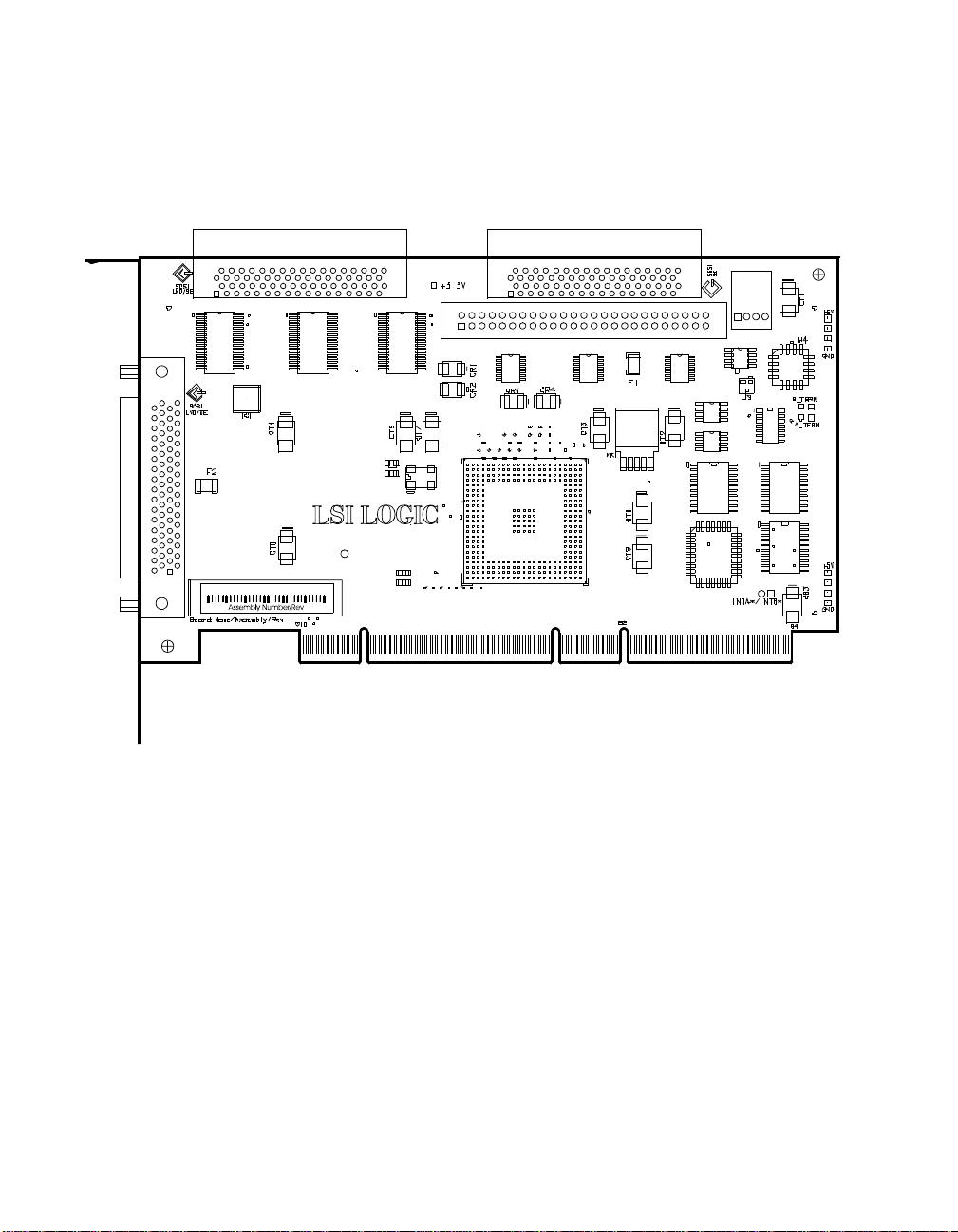
the PCI Local Bus Specification Revision 2.2. Figure 3.1 illustrates the
details of the LSI21040 mechanical drawing.
Figure 3.1 LSI21040 Mechanical Drawing
U3U2U1
VDDA
VSSA
LSI LOGIC HOSTADAPTER
2000 LSI Logic
C
All Rights Reserved
VDDA2
VSSA2
J3
J1T
3.1.2 Electrical Characteristics
J2J4
J5
A23
U15
A1
U6
U7 U8
AC23
AC1
U18
U10
U12
U17
J6
5
U11
U14U13
U16
Under normal conditions, the LSI21040 maximum power requirement
that includes SCSI TERMPWR is: +5 V DC,
operating range 0
°Cto55°C.
Under abnormal conditions, such as a short on SCSI TERMPWR, +5 V
current may be higher. At temperatures of at least 25
is sustained no longer than 30 seconds before the self-resetting
TERMPWR short circuit protection device (F1) opens.
The PCI PRSNT1/ and PRSNT2/ pins are set to indicate a 15 W maximum
configuration.
3-2 Specifying the Technical Characteristics
±5%, 3.0 A, and over the
°C, a current of 4 A
Page 47

3.1.3 Thermal, Atmospheric Characteristics
The thermal, atmospheric characteristics of the LSI21040 are:
• Temperature range: 0 °Cto55°C (dry bulb)
• Relative humidity range: 5% to 90% noncondensing
• Maximum dew point temperature: 32 °C
The following parameters define the storage and transit environment for
the LSI21040:
• Storage Temperature: −45 °Cto+105°C (dry bulb)
• Relative Humidity Range: 5% to 90% noncondensing
3.1.4 Electromagnetic Compliance
The board is designed and implemented to minimize electromagnetic
emissions, susceptibility, and the effects of electromagnetic discharge.
The board carries the CE mark, VCCI, Canada mark, and meets the
requirements of FCC Class B. The board is marked with the FCC
self-certification logo.
3.1.5 Safety Characteristics
The bare board meets or exceeds the requirements of UL flammability
rating 94 V0. The bare board is also marked with the supplier’s name or
trademark, type, and UL flammability rating. Since this board is installed
in a PCI bus slot, all voltages are below the SELV 42.4 V limit.
Physical Environment 3-3
Page 48

3.2 Operational Environment
Use the LSI21040 in PCI computer systems with an ISA/EISA bracket
type. The SDMS operates the board, but the design of the board does
not prevent the use of other software. An on-board flash memory device
is provided to allow BIOS code and open boot code support through PCI
and a serial EEPROM for each channel.
3.2.1 The PCI Interface
The PCI interface operates as a 64-bit DMA bus master. Edge connector
J1 makes the PCI connection, which provides connections on both the
front and back of the board. The signal definitions and pin numbers
conform to the PCI Local Bus Specification Revision 2.2 standard.
Table 3.1 and Table 3.2 show the signal assignments. The on-board
+3.3 V regulator provides power to the PCI portion of the LSI53C1010
device.
Note:
The +3.3 V pins are tied together and decoupled with high
frequency bypass capacitors to ground. No current from
these +3.3 V pins is used on the board. The board derives
power from the +5 V pins, directly and through a 3.3 V
voltage regulator. The PCI +3 V/+5 V pins are used to
differentiate between a 5 V or a 3.3 V PCI environment.
3-4 Specifying the Technical Characteristics
Page 49

Table 3.1 PCI Connector J1 (Front)
Signal Name Pin Signal Name Pin Signal Name Pin Signal Name Pin
−12 V 1 +3.3 V 25 M66EN 49 AD59 71
TCK 2 C_BE3/ 26 KEYWAY 50 AD57 72
GND 3 AD23 27 KEYWAY 51 GND 73
TDO 4 GND 28AD08 52AD55 74
+5 V 5 AD21 29 AD07 53 AD53 75
+5 V 6 AD19 30 +3.3 V 54 GND 76
INTB/ 7 +3.3 V 31 AD05 55 AD51 77
INTD/ 8 AD17 32 AD03 56 AD49 78
GND (PRSNT1/) 9 C_BE2/ 33 GND 57 +3 V / +5 V 79
RESERVED 10GND 34AD01 58AD47 80
GND (PRSNT2/) 11 IRDY/ 35 +3 V / +5 V 59 AD45 81
KEYWAY 12 +3.3 V 36
KEYWAY 13 DEVSEL/ 37 +5 V 61 AD43 83
RESERVED 14 GND 38 +5 V 62 AD41 84
GND 15 LOCK/ 39 KEYWAY xx GND 85
CLK 16 PERR/ 40 KEYWAY xx AD39 86
GND 17 +3.3 V 41
REQ/ 18 SERR/ 42 GND 64 +3 V / +5 V 88
+3 V / +5 V 19 +3.3 V 43
AD31 20 C_BE1/ 44 C_BE4/ 66 AD33 90
AD29 21 AD14 45 GND 67 GND 91
GND 22 GND 46 AD63 68
AD27 23 AD12 47 AD61 69
AD25 24 AD10 48 +3 V / +5 V 70
Note: Highlighted signals are not connected.
ACK64/ 60 GND 82
RESERVED 63 AD37 87
C_BE6/ 65 AD35 89
RESERVED 92
RESERVED 93
GND 94
Operational Environment 3-5
Page 50

Table 3.2 PCI Connector J1 (Back)
Signal Name Pin Signal Name Pin Signal Name Pin Signal Name Pin
TRST/ 1 AD24 25 AD09 49 AD58 71
+12 V 2 IDSEL 26 KEYWAY 50 GND 72
TMS 3 +3.3 V 27 KEYWAY 51 AD56 73
TDI 4 AD22 28 C_BE0/ 52 AD54 74
+5 V 5 AD20 29 +3.3 V 53 +3 V / +5 V 75
INTA/ 6 GND 30AD06 54AD52 76
INTC/ 7 AD18 31 AD04 55 AD50 77
+5 V 8 AD16 32 GND 56 GND 78
RESERVED 9 +3.3 V 33 AD02 57 AD48 79
+3V/+5V 10FRAME/ 34AD00 58AD46 80
RESERVED 11 GND 35 +3V/+5V 59 GND 81
KEYWAY 12 TRDY/ 36 REQ64/ 60 AD44 82
KEYWAY 13 GND 37 +5 V 61 AD42 83
RESERVED 14 STOP/ 38 +5 V 62 +3 V / +5 V 84
RST/ 15 +3.3 V 39 KEYWAY xx AD40 85
+3 V / +5 V 16
GNT/ 17 SBO/ 41 GND 63 GND 87
GND 18 GND 42 C_BE7/ 64 AD36 88
RESERVED 19 PAR 43 C_BE5/ 65 AD34 89
AD30 20 AD15 44 +3 V / +5 V 66 GND 90
+3.3 V 21 +3.3 V 45 PAR64 67 AD32 91
AD28 22 AD13 46 AD62 68
AD26 23 AD11 47 GND 69 GND 93
GND 24 GND 48 AD60 70
Note: Highlighted signals are not connected.
3-6 Specifying the Technical Characteristics
SDONE 40 KEYWAY xx AD38 86
RESERVED 92
RESERVED 94
Page 51

3.2.2 The SCSI Interface
The SCSI interface conforms to ANSI X 3T10.11/1142. The SCSI
interface operates as 16-bit, synchronous or asynchronous, SE or LVD,
and supports Ultra160 SCSI protocols. Arbitration is supported for 8-bit
(at lower SCSI speeds) and 16-bit. Active SE or LVD SCSI termination
is provided automatically. SCSI termination power is supplied by the
board.
Connectors J3 and J4 for Channel A and J2 and J5 for Channel B make
the SCSI interface. Refer to Figure 2.1 on page 2-4 toseeanexample
of this interface. J2 and J4 are 68-pin high density right angle connectors
for internal SCSI connections. J5 is a 50-pin low density vertical
connector. External connector J3 is a shielded 68-pin high density right
angle connector exposed in the back panel bracket.
LVD/SE dual mode, active termination is provided on the LSI21040 for
Channel A. SE SCSI termination is provided for Channel B. The
LSI21040 supplies SCSI bus TERMPWR through a blocking diode and
a self-resetting 1.5 A short circuit protection device. A 40 MHz oscillator
is installed on the LSI21040. This oscillator provides the clock frequency
necessary to support Ultra160 SCSI transfers of up to 160 Mbytes/s.
Table 3.3 and Table 3.4 show the signal assignments for J2 and J5.
Table 3.5 and Table 3.6 show the signal assignments for J4 and J3.
Operational Environment 3-7
Page 52

Table 3.3 Internal Channel B SCSI Connector J2
Signal Pin
GND 1
GND 2
GND 3
GND 4
GND 5
GND 6
GND 7
GND 8
GND 9
GND 10
GND 11
GND 12
GND 13
GND 14
GND 15
GND 16
TERMPWR 17
TERMPWR 18
Note: NC pins are not connected.
N/C 19
GND 20
GND 21
GND 22
GND 23
GND 24
GND 25
GND 26
GND 27
GND 28
GND 29
GND 30
GND 31
GND 32
GND 33
GND 34
SD12 35
Signal Pin
SD13 36
SD14 37
SD15 38
SDP1 39
SD0 40
SD1 41
SD2 42
SD3 43
SD4 44
SD5 45
SD6 46
SD7 47
SDP 48
GND 49
CPRSNT_A 50
TERMPWR 51
TERMPWR 52
Table 3.4 Internal Channel B SCSI Connector J5
Signal PinSignal Pin
N/C 53
GND 54
SATN 55
GND 56
SBSY 57
SACK 58
SRST 59
SMSG 60
SSEL 61
SC_D 62
SREQ 63
SI_O 64
SD8 65
SD9 66
SD10 67
SD11 68
Signal PinSignal PinSignal Pin Signal Pin
GND 1
SD0 2
GND 3
SD1 4
GND 5
SD2 6
GND 7
SD3 8
GND 9
SD4 10
GND 11
SD5 12
GND 13
Note: NC pins are not connected.
3-8 Specifying the Technical Characteristics
SD6 14
GND 15
SD7 16
GND 17
SDP 18
GND 19
GND 20
GND 21
CPRSNT_C 22
N/C 23
N/C 24
N/C 25
TERMPWR 26
N/C 27
N/C 28
GND 29
GND 30
GND 31
SATN 32
GND 33
GND 34
GND 35
SBSY 36
GND 37
SACK 38
GND 39
SRST 40
GND 41
SMSG 42
GND 43
SSEL 44
GND 45
SC_D 46
GND 47
SREQ 48
GND 49
SI_O 50
Page 53

Table 3.5 Internal Channel A SCSI Connector J4
Signal Pin Signal Pin
SD12+ 1
SD13+ 2
SD14+ 3
SD15+ 4
SDP1+ 5
SD00+ 6
SD01+ 7
SD02+ 8
SD03+ 9
SD04+ 10
SD05+ 11
SD06+ 12
SD07+ 13
SDP+ 14
GND 15
DIFFSENS 16
TERMPWR 17
Note: NC pins are not connected.
TERMPWR 18
N/C 19
GND 20
SATN+ 21
GND 22
SBSY+ 23
SACK+ 24
SRST+ 25
SMSG+ 26
SSEL+ 27
SC_D+ 28
SREQ+ 29
SI_O+ 30
SD08+ 31
SD09+ 32
SD10+ 33
SD11+ 34
Table 3.6 External SCSI Connector J3
Signal Pin Signal Pin
SD12+ 1
SD13+ 2
SD14+ 3
SD15+ 4
SDP1+ 5
SD00+ 6
SD01+ 7
SD02+ 8
SD03+ 9
SD04+ 10
SD05+ 11
SD06+ 12
SD07+ 13
SDP+ 14
GND 15
DIFFSENS 16
TERMPWR 17
Note: NC pins are not connected.
TERMPWR 18
N/C 19
GND 20
SATN+ 21
GND 22
SBSY+ 23
SACK+ 24
SRST+ 25
SMSG+ 26
SSEL+ 27
SC_D+ 28
SREQ+ 29
SI_O+ 30
SD08+ 31
SD09+ 32
SD10+ 33
SD11+ 34
SD12− 35
SD13− 36
SD14− 37
SD15− 38
SDP1− 39
SD00− 40
SD01− 41
SD02− 42
SD03− 43
SD04− 44
SD05− 45
SD06− 46
SD07− 47
SDP− 48
GND 49
CPRSNT/ 50
TERMPWR 51
SD12− 35
SD13− 36
SD14− 37
SD15− 38
SDP1− 39
SD00− 40
SD01− 41
SD02− 42
SD03− 43
SD04− 44
SD05− 45
SD06− 46
SD07− 47
SDP− 48
GND 49
CPRSNT/ 50
TERMPWR 51
Signal PinSignal Pin
TERMPWR 52
N/C 53
GND 54
SATN− 55
GND 56
SBSY− 57
SACK− 58
SRST− 59
SMSG− 60
SSEL− 61
SC_D− 62
SREQ− 63
SI_O− 64
SD08− 65
SD09− 66
SD10− 67
SD11− 68
Signal PinSignal Pin
TERMPWR 52
N/C 53
GND 54
SATN− 55
GND 56
SBSY− 57
SACK− 58
SRST− 59
SMSG− 60
SSEL− 61
SC_D− 62
SREQ− 63
SI_O− 64
SD08− 65
SD09− 66
SD10− 67
SD11− 68
Operational Environment 3-9
Page 54

3.2.3 SCSI Activity LED Interface
The SCSI activity LED interface on the LSI21040 is a four-wire
arrangement that allows you to connect an LED harness to the board.
The buffered GPIO0_FETCH line (maximum output low voltage 0.4 V
and minimum output low current 16 mA) is pulled low to complete the
circuit when a harness with an LED is attached. Connector J6 is the
SCSI busy LED connector. Table 3.7 provides the signal definitions for
the SCSI Busy LED connector.
Table 3.7 LED Connector J6
Signal Name Pin
Channel A LED+ 1
Channel A LED− 2
Channel B LED– 3
Channel B LED+ 4
3.3 Subsystem and Subsystem Vendor ID
The Subsystem ID and System Vendor ID for the LSI21040 are provided
in Table 3.8. The EEPROM of the LSI21040 contains the ID numbers.
During system initialization, the ID numbers are loaded into the
Subsystem Vendor ID and Subsystem ID registers of the LSI21040 SCSI
Controller (the LSI53C1010). For more information on the operation of
the Subsystem Vendor ID and Subsystem ID registers, refer to the
LSI53C1010-33 PCI to Dual Channel Ultra3 SCSI Multifunction
Controller Technical Manual.
T able 3.8 Subsystem and Subsystem Vendor ID
Subsystem ID Number
Subsystem Vendor ID 1000
Subsystem ID 1040
3-10 Specifying the Technical Characteristics
Page 55

3.75 pc 10.25 pc 11.25 pc 38.25 pc
34.5 pc
4.333 pc
Appendix A
Glossary of Terms and
Abbreviations
12 pc
12.938 pc
160/m An industry initiative extension of the Ultra160 SCSI specification that
requires support of Double Transition Clocking, Domain Validation, and
Cyclic Redundancy Check.
13.851 pc
34.732 pc
Active
Termination
Address A specific location in memory, designated either numerically or by a
AIP Asynchronous Information Protection provides error checking for
Asynchronous
Data Transfer
BIOS Basic Input/Output System. Software that provides basic read/write
Bit A binary digit. The smallest unit of information a computer uses. The
Bus A collection of unbroken signal lines across which information is
The electrical connection required at each end of the SCSI bus,
composed of active voltage regulation and a set of termination resistors.
Ultra, Ultra2, and Ultra160 SCSI require active termination.
symbolic name.
asynchronous, nondata phases of the SCSI bus.
One of the ways data is transferred over the SCSI bus. It is slower than
synchronous data transfer.
capability. Usually kept as firmware (ROM based). The system BIOS on
the mainboard of a computer is used to boot and control the system. The
SCSI BIOS on the host adapter acts as an extension of the system BIOS.
value of a bit (0 or 1) represents a two-way choice, such as on or off,
true or false, and so on.
transmitted from one part of a computer system to another. Connections
to the bus are made using taps on the lines.
LSI21040 PCI to Dual Channel Ultra160 SCSI Host Adapter A-1
48.583 pc
52.5 pc
Page 56

3.75 pc 10.25 pc 11.25 pc 38.25 pc
34.5 pc
Bus Mastering A high-performance way to transfer data. The host adapter controls the
transfer of data directly to and from system memory without interrupting
the computer’s microprocessor. This is the fastest way for multitasking
operating systems to transfer data.
Byte A unit of information consisting of eight bits.
CISPR A special international committee on radio interference (Committee,
International and Special, for Protection in Radio).
Configuration Refers to the way a computer is set up; the combined hardware
components (computer, monitor, keyboard, and peripheral devices) that
make up a computer system; or the software settings that allow the
hardware components to communicate with each other.
CPU Central Processing Unit. The “brain” of the computer that performs the
actual computations. The term Microprocessor Unit (MPU) is also used.
CRC Cyclic Redundancy Check is an error detection code used in Ultra160
SCSI. Four bytes are transferred with the data to increase the reliability
of data transfers. CRC is used on the Double Transition (DT) Data-In and
DT Data-Out phases.
44.25 pc
Device Driver A program that allows a microprocessor (through the operating system)
to direct the operation of a peripheral device.
4.333 pc
DMA Direct Memory Access.
Differential SCSI A hardware configuration for connecting SCSI devices. It uses a pair of
lines for each signal transfer (as opposed to Single-Ended SCSI which
references each SCSI signal to a common ground).
DMA Bus
Master
A feature that allows a peripheral to control the flow of data to and from
system memory by blocks, as opposed to PIO (Programmed I/O) where
the processor is in control and the flow is by byte.
Domain
Validation
Domain Validation is a software procedure in which a host queries a
device to determine its ability to communicate at the negotiated Ultra160
data rate.
DT Clocking In Double Transition (DT) Clocking data is sampled on both the asserting
and deasserting edge of the REQ/ACK signal. DT clocking may only be
implemented on an LVD SCSI bus.
A-2 Glossary of Terms and Abbreviations
48.583 pc
52.5 pc
Page 57

3.75 pc 10.25 pc 11.25 pc 38.25 pc
34.5 pc
Dword A double word is a group of four consecutive bytes or characters that are
4.333 pc
stored, addressed, transmitted, and operated on as a unit. The lower two
address bits of the least significant byte must equal zero in order to be
Dword aligned.
EEPROM Electronically Erasable Programmable Read Only Memory. A memory
chip typically used to store configuration information. See NVRAM.
EISA Extended Industry Standard Architecture. An extension of the 16-bit ISA
bus standard. It allows devices to perform 32-bit data transfers.
44.25 pc
External SCSI
Device
A SCSI device installed outside the computer cabinet. These devices are
connected in a continuous chain using specific types of shielded cables.
Fast-20 The SCSI Trade Association (STA) supports the use of “Ultra SCSI” over
the term “Fast-20”. Please see Ultra SCSI.
Fast-40 The SCSI Trade Association (STA) supports the use of “Ultra2 SCSI”
over the term “Fast-40”. Please see Ultra2 SCSI.
Fast SCSI A standard for SCSI data transfers. It allows a transfer rate of up to
10 Mbytes/s over an 8-bit SCSI bus and up to 20 Mbytes/s over a 16-bit
SCSI bus.
FCC Federal Communications Commission.
File A named collection of information stored on a disk.
Firmware Software that is permanently stored in ROM. Therefore, it can be
accessed during boot time.
Hard Disk A disk made of metal and permanently sealed into a drive cartridge. A
hard disk can store very large amounts of information.
Host The computer system in which a SCSI host adapter is installed. It uses
the SCSI host adapter to transfer information to and from devices
attached to the SCSI bus.
Host Adapter A circuit board or integrated circuit that provides a SCSI bus connection
to the computer system.
Internal SCSI
Device
A SCSI device installed inside the computer cabinet. These devices are
connected in a continuous chain using an unshielded ribbon cable.
A-3
48.583 pc
52.5 pc
Page 58

3.75 pc 10.25 pc 11.25 pc 38.25 pc
34.5 pc
IRQ Interrupt Request Channel. A path through which a device can get the
immediate attention of the computer’s CPU. The PCI bus assigns an IRQ
path for each SCSI host adapter.
ISA Industry Standard Architecture. A type of computer bus used in most
PCs.Itallowsdevicestosendandreceivedataupto16bitsatatime.
Kbyte Kilobyte. A measure of computer storage equal to 1024 bytes.
Local Bus A way to connect peripherals directly to computer memory. It bypasses
the slower ISA and EISA buses. PCI is a local bus standard.
Logical Unit A subdivision, either logical or physical, of a SCSI device (actually the
place for the device on the SCSI bus). Most devices have only one logical
unit, but up to eight are allowed for each of the eight possible devices on
aSCSIbus.
LUN Logical Unit Number. An identifier, zero to seven, for a logical unit.
LVD Link Low Voltage Differential Link allows greater Ultra2 SCSI device
connectability and longer SCSI cables. LVD Link lowers the amplitude of
noise reflections and allows higher transmission frequencies. Detailed
44.25 pc
information may be found in Section 1.4, “Benefits of LVD Link
Technology,” on page 1-6.
4.333 pc
Mainboard A large circuit board that holds RAM, ROM, the microprocessor, custom
integrated circuits, and other components that make a computer work. It
also has expansion slots for host adapters and other expansion boards.
Main Memory The part of a computer’smemory which is directly accessible by the CPU
(usually synonymous with RAM).
Mbyte Megabyte. A measure of computer storage equal to 1024 kilobytes.
Motherboard See Mainboard. In some countries, the term Motherboard is not
appropriate.
Multitasking The executing of more than one command at the same time. This allows
programs to operate in parallel.
Multithreading The simultaneous accessing of data by more than one SCSI device. This
increases the data throughput.
A-4 Glossary of Terms and Abbreviations
48.583 pc
52.5 pc
Page 59

3.75 pc 10.25 pc 11.25 pc 38.25 pc
34.5 pc
NVRAM NonVolatile Random Access Memory. Actually an EEPROM
4.333 pc
(Electronically Erasable Read Only Memory chip) used to store
configuration information. See EEPROM.
44.25 pc
Operating
System
A program that organizes the internal activities of the computer and its
peripheral devices. An operating system performs basic tasks such as
moving data to and from devices, and managing information in memory.
It also provides the user interface.
Parity Checking A way to verify the accuracy of data transmitted over the SCSI bus. The
parity bit in the transfer is used to make the sum of all the 1 bits either
odd or even (for odd or even parity). If the sum is not correct, the
information may be retransmitted or an error message may appear.
Passive
Termination
The electrical connection required at each end of the SCSI bus,
composed of a set of resistors. It improves the integrity of bus signals.
PCI Peripheral Component Interconnect. A local bus specification that allows
connection of peripherals directly to computer memory. It bypasses the
slower ISA and EISA buses.
Peripheral
Devices
A piece of hardware (such as a video monitor, disk drive, printer, or
CD-ROM) used with a computer and under the computer’s control. SCSI
peripherals are controlled through a SCSI host adapter.
Pin-1
Orientation
The alignment of pin 1 on a SCSI cable connector and the pin-1 position
on the SCSI connector into which it is inserted. External SCSI cables are
always keyed to insure proper alignment, but internal SCSI ribbon cables
sometimes are not keyed.
PIO Programmed Input/Output. A way the CPU can transfer data to and from
memory using the computer’s I/O ports. PIO is usually faster than DMA,
but requires CPU time.
Port Address Also Port Number. The address through which commands are sent to a
host adapter board. This address is assigned by the PCI bus.
Port Number See Port Address.
Queue Tags A way to keep track of multiple commands that allow for increased
throughput on the SCSI bus.
A-5
48.583 pc
52.5 pc
Page 60

3.75 pc 10.25 pc 11.25 pc 38.25 pc
34.5 pc
RAM Random Access Memory. The computer’s primary working memory in
4.333 pc
which program instructions and data are stored and are accessible to the
CPU. Information can be written to and read from RAM. The contents of
RAM are lost when the computer is turned off.
RISC Core LSI Logic SCSI chips contain a RISC (Reduced Instruction Set
Computer) processor, programmed through microcode SCRIPTS.
ROM Read Only Memory. Memory from which information can be read but not
changed. The contents of ROM are not erased when the computer is
turned off.
SCAM SCSI Configured AutoMatically. A method to automatically allocate SCSI
IDs using software when SCAM compliant SCSI devices are attached.
44.25 pc
SCRIPTS
Processor
The SCRIPTS processor allows users to fine tune SCSI operations with
regard to unique vendor commands or new SCSI specifications. The
SCRIPTS processor fetches SCRIPTS instructions from system memory
to control operation of the LSI53C8XX or LSI53C10XX device.
SCSI Small Computer System Interface. A specification for a high-performance
peripheral bus and command set. The original standard is referred to as
SCSI-1.
SCSI-2 The SCSI specification which adds features to the original SCSI
standard.
SCSI-3 The current SCSI specification which adds features to the SCSI-2
standard.
SCSI Bus A host adapter and one or more SCSI peripherals connected by cables
in a linear chain configuration. The host adapter may exist anywhere on
the chain, allowing connection of both internal and external SCSI
devices. A system may have more than one SCSI bus by using multiple
host adapters.
SCSI Device Any device that conforms to the SCSI standard and is attached to the
SCSI bus by a SCSI cable. This includes SCSI host adapters and SCSI
peripherals.
SCSI ID A way to uniquely identify each SCSI device on the SCSI bus. Each SCSI
bus has eight available SCSI IDs numbered 0 through 7 (or 0 through 15
for Wide SCSI). The host adapter usually gets the highest ID, (7 or 15)
giving it priority to control the bus.
A-6 Glossary of Terms and Abbreviations
48.583 pc
52.5 pc
Page 61

3.75 pc 10.25 pc 11.25 pc 38.25 pc
34.5 pc
SCSI SCRIPTS A SCSI programming language that works with the SCRIPTS processor
4.333 pc
that is embedded on the LSI53C8XX or LSI53C10XX device. These
SCRIPTS reside in host computer system memory.
SDMS Storage Device Management System. An LSI Logic software product that
manages SCSI system I/O.
44.25 pc
Single-Ended
SCSI
A hardware specification for connecting SCSI devices. It references each
SCSI signal to a common ground. This is the most common method (as
opposed to differential SCSI which uses a separate ground for each
signal).
STA SCSI Trade Association. A group of companies that cooperate to
promote SCSI parallel interface technology as a viable mainstream I/O
interconnect for commercial computing.
SURElink The domain validation method developed and used by LSI Logic.
SURElink provides three levels of integrity checking: Basic (level 1),
Enhanced (level 2), and Margined (level 3).
Synchronous
Data Transfer
One of the ways data is transf erred over the SCSI bus. Transfers are
clocked with fixed frequency pulses. This is faster than asynchronous
data transfer. Synchronous data transfers are negotiated between the
SCSI host adapter and each SCSI device.
System BIOS Controls the low-level POST (Power-On Self-Test), and basic operation
of the CPU and computer system.
TolerANT A technology developed and used by LSI Logic to improve data integrity,
data transf er rates, and noise immunity, through the use of active
negation and input signal filtering.
Ultra SCSI A standard for SCSI data transfers. It allows a transfer rate of up to
20 Mbytes/s over an 8-bit SCSI bus and up to 40 Mbytes/s over a 16-bit
SCSI bus. SCSI Trade Association (STA) supports using the term “Ultra
SCSI”overtheolderterm“Fast-20”.
Ultra2 SCSI A standard for SCSI data transfers. It allows a transfer rate of up to
40 Mbytes/s over an 8-bit SCSI bus, and up to 80 Mbytes/s over a 16-bit
SCSI bus. SCSI Trade Association (STA) supports using the term “Ultra2
SCSI” over the term “Fast-40”.
Ultra160 SCSI A standard for SCSI data transfers. It allows a transfer rate of up to
160 Mbytes/s over a 16-bit SCSI bus.
A-7
48.583 pc
52.5 pc
Page 62

3.75 pc 10.25 pc 11.25 pc 38.25 pc
34.5 pc
VCCI Voluntary Control Council for Interference.
4.333 pc
VDE Verband Deucher Elektroniker (Association of German Electrical
Engineers).
Virtual Memory Space on a hard disk that can be used as if it were RAM.
Wide SCSI A SCSI-2 feature allowing 16-bit or 32-bit transfers on the SCSI bus. This
dramatically increases the transfer rate over the standard 8-bit SCSI bus.
Wide Ultra SCSI The SCSI Trade Association (STA) term for SCSI bus width 16-bits, SCSI
bus speed maximum data rate 40 Mbytes/s.
44.25 pc
Wide Ultra2
SCSI
The SCSI Trade Association (STA) term for SCSI bus width 16-bits, SCSI
bus speed maximum data rate 80 Mbytes/s.
Word A two byte (or 16-bit) unit of information.
A-8 Glossary of Terms and Abbreviations
48.583 pc
52.5 pc
Page 63

Index
A
asynchronous information protection
feature of Ultra160 1-6
B
board characteristics 1-4
bus configurations 2-17
C
chained connection 2-11, 2-16
connecting the SCSI peripherals 2-6
cyclic redundancy check
feature of Ultra160 1-5
D
desktop management interface 1-7
detailed installation procedure 2-2
domain validation verifying 1-7
double transition clocking 1-5
duplication of SCSI IDs 2-23
E
edge connector 2-4
electrical characteristics 3-2
electromagnetic compliance 3-3
erroneous termination 2-17
external SCSI bus connections 2-14
external SCSI device 2-15
external SCSI device termination 2-20
F
features 1-2
front panel LED 2-13
G
GPIO0_FETCH line 3-10
H
hardware connections 2-4
I
inserting the host adapter 2-2, 2-5
installation procedure 2-2
installation procedure check list 2-25
internal SCSI bus connections 2-9
internal SCSI device connection 2-10
internal SCSI device termination 2-19
internal SCSI ribbon cable 2-9
L
LED
cable 2-13
connector 2-13
LED connector
SCSI bus activity 1-4
LVD Link technology benefits 1-6
M
multiple internal SCSI devices 2-12
O
operational environment 3-4
P
PCI connector J1 (back) 3-6
PCI connector J1 (front) 3-5
PCI interface 1-2
peripheral device SCSI IDs 2-23
peripheral device terminators 2-17
physical characteristics 3-1
physical environment 3-1
, 3-4
R
ribbon cable 2-6
S
safety characteristics 3-3
SCSI
bus connections 2-6
bus termination 2-17
IDs 2-23
interface 1-3 to 1-4
LED connector 2-13
, 3-7
LSI21040 PCI to Dual Channel Ultra160 SCSI Host Adapter IX-1
Page 64

SCSI (Cont.)
peripherals 2-6
ribbon cable 2-9
serial EEPROM 1-4
setting SCSI IDs 2-23
SURElink benefits 1-7
T
termination 2-17
(erroneous) 2-17
thermal, atmospheric characteristics 3-3
TolerANT technology benefits 1-7
U
Ultra SCSI 2-6
Ultra160 SCSI 1-5
asynchronous information protection 1-6
benefits 1-5
cyclic redundancy check 1-5
domain validation 1-5
double transition clocking 1-5
IX-2 Index
Page 65

Customer Feedback
We would appreciate your feedback on this document. Please copy the
following page, add your comments, and fax it to us at the number
shown.
If appropriate, please also fax copies of any marked-up pages from this
document.
Important:
Thank you for your help in improving the quality of our documents.
Please include your name, phone number, fax number, and
company address so that we may contact you directly for
clarification or additional information.
LSI21040 PCI to Dual Channel Ultra160 SCSI Host Adapter
Page 66

Reader’s Comments
Fax your comments to: LSI Logic Corporation
Technical Publications
M/S E-198
Fax: 408.433.4333
Please tell us how you rate this document: LSI21040 PCI to Ultra160
SCSI Dual Channel Host Adapter User’s Guide. Place a check mark in
the appropriate blank for each category.
Excellent Good Average Fair Poor
Completeness of information ____ ____ ____ ____ ____
Clarity of information ____ ____ ____ ____ ____
Ease of finding information ____ ____ ____ ____ ____
Technical content ____ ____ ____ ____ ____
Usefulness of examples and
illustrations
Overall manual ____ ____ ____ ____ ____
____ ____ ____ ____ ____
Whatcouldwedotoimprovethisdocument?
If you found errors in this document, please specify the error and page
number. If appropriate, please fax a marked-up copy of the page(s).
Please complete the information below so that we may contact you
directly for clarification or additional information.
Name Date
Telephone
Fax
Title
Department Mail Stop
Company Name
Street
City, State, Zip
Customer Feedback
Page 67

U.S. Distributors
by State
A. E. Avnet Electronics
http://www.hh.avnet.com
B. M. Bell Microproducts,
Inc. (for HAB’s)
http://www.bellmicro.com
I. E. Insight Electronics
http://www.insight-electronics.com
W.E. Wyle Electronics
http://www.wyle.com
Alabama
Daphne
I. E. Tel: 334.626.6190
Huntsville
A. E. Tel: 256.837.8700
B. M. Tel: 256.705.3559
I. E. Tel:256.830.1222
W.E. Tel: 800.964.9953
Alaska
A. E. Tel: 800.332.8638
Arizona
Phoenix
A. E. Tel: 480.736.7000
B. M. Tel: 602.267.9551
W.E. Tel: 800.528.4040
Tempe
I. E. Tel:480.829.1800
Tucson
A. E. Tel: 520.742.0515
Arkansas
W.E. Tel: 972.235.9953
California
Agoura Hills
B. M. Tel: 818.865.0266
Granite Bay
B. M. Tel: 916.523.7047
Irvine
A. E. Tel: 949.789.4100
B. M. Tel: 949.470.2900
I. E. Tel:949.727.3291
W.E. Tel: 800.626.9953
Los Angeles
A. E. Tel: 818.594.0404
W.E. Tel: 800.288.9953
Sacramento
A. E. Tel: 916.632.4500
W.E. Tel: 800.627.9953
San Diego
A. E. Tel: 858.385.7500
B. M. Tel: 858.597.3010
I. E. Tel:800.677.6011
W.E. Tel: 800.829.9953
San Jose
A. E. Tel: 408.435.3500
B. M. Tel: 408.436.0881
I. E. Tel:408.952.7000
Santa Clara
W.E. Tel: 800.866.9953
Woodland Hills
A. E. Tel: 818.594.0404
Westlake Village
I. E. Tel:818.707.2101
Colorado
Denver
A. E. Tel: 303.790.1662
B. M. Tel: 303.846.3065
W. E. Tel: 800.933.9953
Englewood
I. E. Tel: 303.649.1800
Idaho Springs
B. M. Tel: 303.567.0703
Connecticut
Cheshire
A. E. Tel: 203.271.5700
I. E. Tel: 203.272.5843
Wallingford
W. E. Tel: 800.605.9953
Delaware
North/South
A. E. Tel: 800.526.4812
Tel: 800.638.5988
B. M. Tel: 302.328.8968
W. E. Tel: 856.439.9110
Florida
Altamonte Springs
B. M. Tel: 407.682.1199
I. E. Tel: 407.834.6310
Boca Raton
I. E. Tel: 561.997.2540
Bonita Springs
B. M. Tel: 941.498.6011
Clearwater
I. E. Tel: 727.524.8850
Fort Lauderdale
A. E. Tel: 954.484.5482
W. E. Tel: 800.568.9953
Miami
B. M. Tel: 305.477.6406
Orlando
A. E. Tel: 407.657.3300
W. E. Tel: 407.740.7450
Tampa
W. E. Tel: 800.395.9953
St. Petersburg
A. E. Tel: 727.507.5000
Georgia
Atlanta
A. E. Tel: 770.623.4400
B. M. Tel: 770.980.4922
W. E. Tel: 800.876.9953
Duluth
I. E. Tel: 678.584.0812
Hawaii
A. E. Tel: 800.851.2282
Idaho
A. E. Tel: 801.365.3800
W. E. Tel: 801.974.9953
Illinois
North/South
A. E. Tel: 847.797.7300
Tel: 314.291.5350
Chicago
B. M. Tel: 847.413.8530
W. E. Tel: 800.853.9953
Schaumburg
I. E. Tel:847.885.9700
Indiana
Fort Wayne
I. E. Tel:219.436.4250
W. E. Tel: 888.358.9953
Indianapolis
A. E. Tel: 317.575.3500
Iowa
W. E. Tel: 612.853.2280
Cedar Rapids
A. E. Tel: 319.393.0033
Kansas
W. E. Tel: 303.457.9953
Kansas City
A. E. Tel: 913.663.7900
Lenexa
I. E. Tel:913.492.0408
Kentucky
W. E. Tel: 937.436.9953
Central/Northern/ Western
A. E. Tel: 800.984.9503
Tel: 800.767.0329
Tel: 800.829.0146
Louisiana
W. E. Tel: 713.854.9953
North/South
A. E. Tel: 800.231.0253
Tel: 800.231.5775
Maine
A. E. Tel: 800.272.9255
W. E. Tel: 781.271.9953
Maryland
Baltimore
A. E. Tel: 410.720.3400
W. E. Tel: 800.863.9953
Columbia
B. M. Tel: 800.673.7461
I. E. Tel:410.381.3131
Massachusetts
Boston
A. E. Tel: 978.532.9808
W. E. Tel: 800.444.9953
Burlington
I. E. Tel:781.270.9400
Marlborough
B. M. Tel: 800.673.7459
Woburn
B. M. Tel: 800.552.4305
Michigan
Brighton
I. E. Tel: 810.229.7710
Detroit
A. E. Tel: 734.416.5800
W. E. Tel: 888.318.9953
Clarkston
B. M. Tel: 877.922.9363
Minnesota
Champlin
B. M. Tel: 800.557.2566
Eden Prairie
B. M. Tel: 800.255.1469
Minneapolis
A. E. Tel: 612.346.3000
W. E. Tel: 800.860.9953
St. Louis Park
I. E. Tel: 612.525.9999
Mississippi
A. E. Tel: 800.633.2918
W. E. Tel: 256.830.1119
Missouri
W. E. Tel: 630.620.0969
St. Louis
A. E. Tel: 314.291.5350
I. E. Tel: 314.872.2182
Montana
A. E. Tel: 800.526.1741
W. E. Tel: 801.974.9953
Nebraska
A. E. Tel: 800.332.4375
W. E. Tel: 303.457.9953
Nevada
Las Vegas
A. E. Tel: 800.528.8471
W. E. Tel: 702.765.7117
New Hampshire
A. E. Tel: 800.272.9255
W. E. Tel: 781.271.9953
New Jersey
North/South
A. E. Tel: 201.515.1641
Tel: 609.222.6400
Mt. Laurel
I. E. Tel: 856.222.9566
Pine Brook
B. M. Tel: 973.244.9668
W. E. Tel: 800.862.9953
Parsippany
I. E. Tel: 973.299.4425
Wayne
W. E. Tel: 973.237.9010
New Mexico
W. E. Tel: 480.804.7000
Albuquerque
A. E. Tel: 505.293.5119
Page 68

U.S. Distributors
by State
(Continued)
New York
Hauppauge
I. E. Tel:516.761.0960
Long Island
A. E. Tel: 516.434.7400
W.E. Tel: 800.861.9953
Rochester
A. E. Tel: 716.475.9130
I. E. Tel:716.242.7790
W.E. Tel: 800.319.9953
Smithtown
B. M. Tel: 800.543.2008
Syracuse
A. E. Tel: 315.449.4927
North Carolina
Raleigh
A. E. Tel: 919.859.9159
I. E. Tel:919.873.9922
W.E. Tel: 800.560.9953
North Dakota
A. E. Tel: 800.829.0116
W.E. Tel: 612.853.2280
Ohio
Cleveland
A. E. Tel: 216.498.1100
W.E. Tel: 800.763.9953
Dayton
A. E. Tel: 614.888.3313
I. E. Tel:937.253.7501
W.E. Tel: 800.575.9953
Strongsville
B. M. Tel: 440.238.0404
Valley View
I. E. Tel:216.520.4333
Oklahoma
W.E. Tel: 972.235.9953
Tulsa
A. E. Tel: 918.459.6000
I. E. Tel:918.665.4664
Oregon
Beaverton
B. M. Tel: 503.524.1075
I. E. Tel:503.644.3300
Portland
A. E. Tel: 503.526.6200
W.E. Tel: 800.879.9953
Pennsylvania
Mercer
I. E. Tel:412.662.2707
Philadelphia
A. E. Tel: 800.526.4812
B. M. Tel: 877.351.2355
W.E. Tel: 800.871.9953
Pittsburgh
A. E. Tel: 412.281.4150
W.E. Tel: 440.248.9996
Rhode Island
A. E. 800.272.9255
W.E. Tel: 781.271.9953
South Carolina
A. E. Tel: 919.872.0712
W. E. Tel: 919.469.1502
South D akota
A. E. Tel: 800.829.0116
W. E. Tel: 612.853.2280
Tennessee
W. E. Tel: 256.830.1119
East/West
A. E. Tel: 800.241.8182
Tel: 800.633.2918
Texas
Arlington
B. M. Tel: 817.417.5993
Austin
A. E. Tel: 512.219.3700
B. M. Tel: 512.258.0725
I. E. Tel: 512.719.3090
W. E. Tel: 800.365.9953
Dallas
A. E. Tel: 214.553.4300
B. M. Tel: 972.783.4191
W. E. Tel: 800.955.9953
El Paso
A. E. Tel: 800.526.9238
Houston
A. E. Tel: 713.781.6100
B. M. Tel: 713.917.0663
W. E. Tel: 800.888.9953
Richardson
I. E. Tel: 972.783.0800
Rio Grande Valley
A. E. Tel: 210.412.2047
Stafford
I. E. Tel: 281.277.8200
Utah
Centerville
B. M. Tel: 801.295.3900
Murray
I. E. Tel: 801.288.9001
Salt Lake City
A. E. Tel: 801.365.3800
W. E. Tel: 800.477.9953
Vermont
A. E. Tel: 800.272.9255
W. E. Tel: 716.334.5970
Virginia
A. E. Tel: 800.638.5988
W. E. Tel: 301.604.8488
Haymarket
B. M. Tel: 703.754.3399
Springfield
B. M. Tel: 703.644.9045
Washington
Kirkland
I. E. Tel:425.820.8100
Maple Valley
B. M. Tel: 206.223.0080
Seattle
A. E. Tel: 425.882.7000
W. E. Tel: 800.248.9953
West Virginia
A. E. Tel: 800.638.5988
Wisconsin
Milwaukee
A. E. Tel: 414.513.1500
W. E. Tel: 800.867.9953
Wauwatosa
I. E. Tel:414.258.5338
Wyoming
A. E. Tel: 800.332.9326
W. E. Tel: 801.974.9953
Page 69

Direct Sales
Representatives by State
(Components and Boards)
E. A. Earle Associates
E. L. Electrodyne - UT
GRP Group 2000
I. S. Infinity Sales,Inc.
ION ION Associates, Inc.
R. A. Rathsburg Associ-
ates, Inc.
SGY Synergy Associates,
Inc.
Arizona
Tempe
E. A. Tel: 480.921.3305
California
Calabasas
I. S. Tel:818.880.6480
Irvine
I. S. Tel:714.833.0300
San Diego
E. A. Tel: 619.278.5441
Illinois
Elmhurst
R. A. Tel: 630.516.8400
Indiana
Cicero
R. A. Tel: 317.984.8608
Ligonier
R. A. Tel: 219.894.3184
Plainfield
R. A. Tel: 317.838.0360
Massachusetts
Burlington
SGY Tel: 781.238.0870
Michigan
Byron Center
R. A. Tel: 616.554.1460
Good Rich
R. A. Tel: 810.636.6060
Novi
R. A. Tel: 810.615.4000
North Carolina
Cary
GRP Tel: 919.481.1530
Ohio
Columbus
R. A. Tel: 614.457.2242
Dayton
R. A. Tel: 513.291.4001
Independence
R. A. Tel: 216.447.8825
Pennsylvania
Somerset
R. A. Tel: 814.445.6976
Texas
Austin
ION T el:512.794.9006
Arlington
ION T el:817.695.8000
Houston
ION T el:281.376.2000
Utah
Salt Lake City
E. L. Tel: 801.264.8050
Wisconsin
Muskego
R. A. Tel: 414.679.8250
Saukville
R. A. Tel: 414.268.1152
Page 70

Sales Offices and Design
Resource Centers
LSI Logic Corporation
CorporateHeadquarters
1551 McCarthy Blvd
Milpitas CA 95035
Tel: 408.433.8000
Fax: 408.433.8989
NORTH AMERICA
California
Irvine
18301 Von Karman Ave
Suite 900
Irvine, CA 92612
♦Tel: 949.809.4600
Fax: 949.809.4444
Pleasanton Design Center
5050 Hopyard Road, 3rd Floor
Suite 300
Pleasanton, CA 94588
Tel: 925.730.8800
Fax: 925.730.8700
San Diego
7585 Ronson Road
Suite 100
San Diego, CA 92111
Tel: 858.467.6981
Fax: 858.496.0548
Silicon Valley
1551 McCarthy Blvd
Sales Office
M/S C-500
Milpitas, CA 95035
♦Tel: 408.433.8000
Fax: 408.954.3353
Design Center
M/S C-410
Tel: 408.433.8000
Fax:408.433.7695
Wireless Design Center
11452 El Camino Real
Suite 210
San Diego, CA 92130
Tel: 858.350.5560
Fax: 858.350.0171
Colorado
Boulder
4940 Pearl East Circle
Suite 201
Boulder,CO 80301
♦Tel: 303.447.3800
Fax: 303.541.0641
Colorado Springs
4420 Arrowswest Drive
Colorado Springs, CO 80907
Tel: 719.533.7000
Fax: 719.533.7020
Fort Collins
2001 Danfield Court
Fort Collins,CO 80525
Tel: 970.223.5100
Fax:970.206.5549
Florida
Boca Raton
2255 Glades Road
Suite 324A
Boca Raton, FL 33431
Tel: 561.989.3236
Fax:561.989.3237
Georgia
Alpharetta
2475 North Winds Parkway
Suite 200
Alpharetta, GA 30004
Tel: 770.753.6146
Fax:770.753.6147
Illinois
Oakbrook Terrace
Two Mid American Plaza
Suite 800
Oakbrook Terrace,IL 60181
Tel: 630.954.2234
Fax:630.954.2235
Kentucky
Bowling Green
1262 Chestnut Street
Bowling Green, KY 42101
Tel: 270.793.0010
Fax:270.793.0040
Maryland
Bethesda
6903 Rockledge Drive
Suite 230
Bethesda, MD 20817
Tel: 301.897.5800
Fax:301.897.8389
Massachusetts
Waltham
200 West Street
Waltham,MA 02451
♦Tel: 781.890.0180
Fax:781.890.6158
Burlington - Mint Technology
77 South Bedford Street
Burlington, MA 01803
Tel: 781.685.3800
Fax:781.685.3801
Minnesota
Minneapolis
8300 Norman Center Drive
Suite 730
Minneapolis,MN 55437
♦Tel: 612.921.8300
Fax:612.921.8399
New Jersey
Red Bank
125 Half Mile Road
Suite 200
Red Bank, NJ 07701
Tel: 732.933.2656
Fax:732.933.2643
Cherry Hill - Mint Technology
215 Longstone Drive
Cherry Hill, NJ 08003
Tel: 856.489.5530
Fax:856.489.5531
New York
Fairport
550 Willowbrook Office Park
Fairport, NY 14450
Tel: 716.218.0020
Fax:716.218.9010
North Carolina
Raleigh
Phase II
4601 Six Forks Road
Suite 528
Raleigh, NC 27609
Tel: 919.785.4520
Fax:919.783.8909
Oregon
Beaverton
15455 NW Greenbrier Parkway
Suite 235
Beaverton, OR 97006
Tel: 503.645.0589
Fax:503.645.6612
Texas
Austin
9020 Capital of TX Highway North
Building 1
Suite 150
Austin, TX 78759
Tel: 512.388.7294
Fax:512.388.4171
Plano
500 NorthCentral Expressway
Suite 440
Plano,TX 75074
♦Tel: 972.244.5000
Fax:972.244.5001
Houston
20405 State Highway 249
Suite 450
Houston, TX 77070
Tel: 281.379.7800
Fax:281.379.7818
Canada
Ontario
Ottawa
260 Hearst Way
Suite 400
Kanata, ON K2L 3H1
♦Tel: 613.592.1263
Fax: 613.592.3253
INTERNATIONAL
France
Paris
LSI Logic S.A.
Immeuble Europa
53 bis Avenue de l'Europe
B.P. 139
78148 Velizy-Villacoublay
Cedex, Paris
♦Tel: 33.1.34.63.13.13
Fax: 33.1.34.63.13.19
Germany
Munich
LSI Logic GmbH
Orleansstrasse 4
81669 Munich
♦Tel: 49.89.4.58.33.0
Fax:49.89.4.58.33.108
Stuttgart
Mittlerer Pfad 4
D-70499 Stuttgart
♦Tel: 49.711.13.96.90
Fax: 49.711.86.61.428
Italy
Milan
LSI Logic S.P.A.
Centro Direzionale Colleoni
Palazzo Orione Ingresso 1
20041 Agrate Brianza, Milano
♦Tel: 39.039.687371
Fax: 39.039.6057867
Japan
Tokyo
LSI Logic K.K.
Rivage-Shinagawa Bldg. 14F
4-1-8 Kounan
Minato-ku, Tokyo108-0075
♦Tel: 81.3.5463.7821
Fax: 81.3.5463.7820
Osaka
Crystal Tower 14F
1-2-27 Shiromi
Chuo-ku, Osaka 540-6014
♦Tel: 81.6.947.5281
Fax: 81.6.947.5287
Page 71

Sales Offices and Design
Resource Centers
(Continued)
Korea
Seoul
LSI Logic Corporation of
Korea Ltd
10th Fl., Haesung 1 Bldg.
942, Daechi-dong,
Kangnam-ku, Seoul, 135-283
Tel: 82.2.528.3400
Fax: 82.2.528.2250
The Netherlands
Eindhoven
LSI Logic Europe Ltd
World TradeCenter Eindhoven
Building ‘Rijder’
Bogert 26
5612 LZ Eindhoven
Tel: 31.40.265.3580
Fax: 31.40.296.2109
Singapore
Singapore
LSI Logic Pte Ltd
7 TemasekBoulevard
#28-02 Suntec Tower One
Singapore 038987
Tel: 65.334.9061
Fax: 65.334.4749
Sweden
Stockholm
LSI Logic AB
Finlandsgatan 14
164 74 Kista
♦Tel: 46.8.444.15.00
Fax: 46.8.750.66.47
Taiwan
Taipei
LSI Logic Asia, Inc.
Taiwan Branch
10/F 156 Min Sheng E. Road
Section 3
Taipei, TaiwanR.O.C.
Tel: 886.2.2718.7828
Fax: 886.2.2718.8869
United Kingdom
Bracknell
LSI Logic Europe Ltd
Greenwood House
London Road
Bracknell, Berkshire RG12 2UB
♦Tel: 44.1344.426544
Fax: 44.1344.481039
♦Sales Offices with
Design Resource Centers
Page 72

International Distributors
Australia
New South Wales
ReptechnicPty Ltd
3/36 Bydown Street
Neutral Bay,NSW 2089
♦Tel: 612.9953.9844
Fax: 612.9953.9683
Belgium
Acal nv/sa
Lozenberg 4
1932 Zaventem
Tel: 32.2.7205983
Fax: 32.2.7251014
China
Beijing
LSI Logic International
Services Inc.
Beijing Representative
Office
Room 708
Canway Building
66 Nan Li Shi Lu
Xicheng District
Beijing 100045, China
Tel: 86.10.6804.2534 to 38
Fax: 86.10.6804.2521
France
Rungis Cedex
Azzurri Technology France
22 Rue Saarinen
Sillic 274
94578 Rungis Cedex
Tel: 33.1.41806310
Fax: 33.1.41730340
Germany
Haar
EBV Elektronik
Hans-Pinsel Str. 4
D-85540 Haar
Tel: 49.89.4600980
Fax: 49.89.46009840
Munich
Avnet Emg GmbH
Stahlgruberring 12
81829 Munich
Tel: 49.89.45110102
Fax:49.89.42.27.75
Wuennenberg-Haaren
Peacock AG
Graf-Zepplin-Str14
D-33181 Wuennenberg-Haaren
Tel: 49.2957.79.1692
Fax: 49.2957.79.9341
Hong Kong
Hong Kong
AVT Industrial Ltd
Unit 608 Tower 1
Cheung Sha Wan Plaza
833 Cheung Sha Wan Road
Kowloon,Hong Kong
Tel: 852.2428.0008
Fax:852.2401.2105
Serial System (HK) Ltd
2301 Nanyang Plaza
57 Hung ToRoad, Kwun Tong
Kowloon,Hong Kong
Tel: 852.2995.7538
Fax: 852.2950.0386
India
Bangalore
Spike Technologies India
Private Ltd
951, Vijayalakshmi Complex,
2nd Floor, 24th Main,
J P Nagar II Phase,
Bangalore, India 560078
♦Tel: 91.80.664.5530
Fax: 91.80.664.9748
Israel
Tel Aviv
Eastronics Ltd
11 Rozanis Street
P.O. Box 39300
Tel Aviv 61392
Tel: 972.3.6458777
Fax: 972.3.6458666
Japan
Tokyo
Daito Electron
Sogo Kojimachi No.3 Bldg
1-6 Kojimachi
Chiyoda-ku,Tokyo 102-8730
Tel: 81.3.3264.0326
Fax: 81.3.3261.3984
Global Electronics
Corporation
NichibeiTime24Bldg. 35 Tansu-cho
Shinjuku-ku,Tokyo 162-0833
Tel: 81.3.3260.1411
Fax: 81.3.3260.7100
Technical Center
Tel: 81.471.43.8200
Marubeni Solutions
1-26-20 Higashi
Shibuya-ku,Tokyo 150-0001
Tel: 81.3.5778.8662
Fax: 81.3.5778.8669
Shinki Electronics
Myuru Daikanyama 3F
3-7-3 Ebisu Minami
Shibuya-ku,Tokyo 150-0022
Tel: 81.3.3760.3110
Fax: 81.3.3760.3101
Yokohama-City
Innotech
2-15-10 Shin Yokohama
Kohoku-ku
Yokohama-City, 222-8580
Tel: 81.45.474.9037
Fax: 81.45.474.9065
Macnica Corporation
Hakusan High-Tech Park
1-22-2 Hadusan, Midori-Ku,
Yokohama-City, 226-8505
Tel: 81.45.939.6140
Fax: 81.45.939.6141
The Netherlands
Eindhoven
Acal Nederland b.v.
Beatrix de Rijkweg 8
5657 EG Eindhoven
Tel: 31.40.2.502602
Fax: 31.40.2.510255
Switzerland
Brugg
LSI Logic Sulzer AG
Mattenstrasse 6a
CH 2555 Brugg
Tel: 41.32.3743232
Fax: 41.32.3743233
Taiwan
Taipe i
Avnet-Mercuries
Corporation, Ltd
14F, No. 145,
Sec. 2,Chien Kuo N. Road
Taipei, Taiwan,R.O.C.
Tel: 886.2.2516.7303
Fax:886.2.2505.7391
Lumax International
Corporation, Ltd
7th Fl., 52, Sec. 3
Nan-Kang Road
Taipei, Taiwan,R.O.C.
Tel: 886.2.2788.3656
Fax:886.2.2788.3568
Prospect Technology
Corporation, Ltd
4Fl., No. 34, Chu Luen Street
Taipei, Taiwan,R.O.C.
Tel: 886.2.2721.9533
Fax:886.2.2773.3756
Wintech Microeletronics
Co., Ltd
7F., No. 34, Sec. 3, Pateh Road
Taipei, Taiwan,R.O.C.
Tel: 886.2.2579.5858
Fax:886.2.2570.3123
United Kingdom
Maidenhead
Azzurri TechnologyLtd
16 Grove Park Business Estate
WalthamRoad
White Waltham
Maidenhead, Berkshire SL6 3LW
Tel: 44.1628.826826
Fax: 44.1628.829730
Milton Keynes
Ingram Micro (UK) Ltd
Garamonde Drive
Wymbush
Milton Keynes
BuckinghamshireMK8 8DF
Tel: 44.1908.260422
Swindon
EBV Elektronik
12 Interface Business Park
Bincknoll Lane
Wootton Bassett,
Swindon, Wiltshire SN4 8SY
Tel: 44.1793.849933
Fax: 44.1793.859555
♦Sales Offices with
Design Resource Centers
 Loading...