

Page 1

USER’S
GUIDE
PCI Storage Device
Management System
SDMS™ 4.0
September 2001
Version 12
®
DB15-000099-04
Page 2

This document contains proprietary information of LSI Logic Corporation. The
information contained herein is not to be used by or disclosed to third parties
without the express written permission of an officer of LSI Logic Corporation.
LSI Logic products are not intended for use in life-support appliances, devices,
or systems. Use of any LSI Logic product in such applications without written
consent of the appropriate LSI Logic officer is prohibited.
Document DB15-000099-04 Twelfth Version (September 2001)
This document describes Version 12 of the LSI Logic PCI Storage Device
Management System SDMS™ 4.0 product and will remain the official reference
source for all revisions/releases of this product until rescinded by an update.
LSI Logic Corporation reserves the right to make changes to any products herein
at any time without notice. LSI Logic does not assume any responsibility or
liability arising out of the application or use of any product described herein,
except as expressly agreed to in writing by LSI Logic; nor does the purchase or
use of a product from LSI Logic convey a license under any patent rights,
copyrights, trademark rights, or any other of the intellectual property rights of
LSI Logic or third parties.
Copyright © 1993–2001 by LSI Logic Corporation. All rights reserved.
TRADEMARK ACKNOWLEDGMENT
The LSI Logic logo design, SCRIPTS, Symbios, and SDMS are registered
trademarks or trademarks of LSI Logic Corporation. MS-DOS is a registered
trademark of Microsoft Corporation. Windows and Windows NT are registered
trademarks of Microsoft Corporation. OS/2 is a registered trademark of the
International Business Machines Corporation. Solaris is a trademark of Sun
Microsystems, Inc. SCO and UnixWare are registered trademarks and SCO
OpenServer is a trademark of The Santa Cruz Operation, Inc. UNIX is a
registered trademark of The Open Group. NetWare is a registered trademark of
Novell, Inc. Linux is a registered trademark of Linus Torvalds. InstallShield is a
registered trademark of InstallShield Software Corporation. All other brand and
product names may be trademarks of their respective companies.
MH
To receive product literature, visit us at http://www.lsilogic.com
For a current list of our distributors, sales offices, and design resource
centers, view our web page located at
http://www.lsilogic.com/contacts/na_salesoffices.html
ii
Copyright © 1993–2001 by LSI Logic Corporation. All rights reserved.
Page 3

Audience
Preface
This book is the user’s guide for the PCI Storage Device Management
System SDMS™ 4.0. Version 12 of this user's guide is intended to
explain how to install and configure the LSI Logic SDMS software in your
PCI computer system.
This document was prepared for OEM customers and provides an
overview of the LSI Logic SDMS software. This document explains the
installation of software drivers as they relate to specific operating
systems.
• Chapter 1, Using the SDMS Software, describes the standard
method of interfacing SCSI I/O subsystems with devices, operating
systems, and application software.
• Chapter 2, SCSI BIOS and Configuration Utility, describes the
SDMS SCSI BIOS and its Configuration Utility, which allows
modifications or changes to the host adapters. It also provides
information about the Multilanguage Configuration Utility.
• Chapter 3, Windows 95, Windows 98, Windows Me Device Driver
Installation, describes the SYMC8XX.MPD, SYM_HI.MPD, and
SYM_U3.MPD drivers along with installation instructions for new and
existing Windows 95/98 systems.
• Chapter 4, Windows NT 4.0 Device Driver Installation, describes
the SYMC8XX.SYS, SYM_HI.SYS, and SYM_U3.SYS drivers along
with installation instructions for new and existing Windows NT
systems. This chapter also includes Windows NT DMI 2.0
Component Instrumentation information.
PCI Storage Device Management System SDMS 4.0 User’s Guide iii
Copyright © 1993–2001 by LSI Logic Corporation. All rights reserved.
Page 4

• Chapter 5,Windows 2000 Device Driver Installation, describes the
SYMC8XX.SYS, SYM_HI.SYS, SYM_895A.SYS, and SYM_U3.SYS
drivers along with installation instructions for new and existing
Windows 2000 systems. This chapter also includes Windows 2000
DMI 2.0 Component Instrumentation information.
• Chapter 6, DOS Device Driver Installation, describes the
ASPI8XX.SYS, SYMDISK.SYS, and SYMCD.SYS drivers. It also
provides information about various DOS utilities.
• Chapter 7, OS/2 Device Driver Installation, describes the
SYM8XX.ADD and SYMHI.ADD drivers along with installation
instructions for new or existing OS/2 systems.
• Chapter 8, SCO OpenServer 5 Device Driver Installation,
describes the Boot Time Loadable Driver (BTLD) along with
installation instructions for new or existing SCO UNIX systems.
• Chapter 9, UnixWare 7 Device Driver Installation, describes the
C8XX driver along with the installation instructions fornew or existing
UnixWare systems.
• Chapter 10, Solaris Device Driver Installation, describes the
SYMHISL driver along with installation instructions for new or
existing Solaris systems.
• Chapter 11, Linux Device Driver Installation, describes Linux
drivers to use with LSI Logic controllers along with installation
instructions and patch information.
• Chapter 12, NetWare Device Driver Installation, describes NWPA
LSI8XXNW.HAM, LSIHINW.HAM,and LSI_U3NW.HAMdrivers along
with installation instructions for new or existing NetWare systems.
• Appendix A, Glossary of Terms and Abbreviations, describes
various terminology that is referenced throughout this user’s guide.
iv Preface
Copyright © 1993–2001 by LSI Logic Corporation. All rights reserved.
Page 5

Related Publications
LSI8750SP PCI to Ultra SCSI Host Adapter User’s Guide, Version 2.1,
LSI Logic Corporation, Order Number 14020.A
LSI8751SP PCI to Ultra SCSI Host Adapter User’s Guide, Version 2.1,
LSI Logic Corporation, Order Number S14016.A
LSI8751SPE PCI to Ultra SCSI Host Adapter User’s Guide, Version 1.1,
LSI Logic Corporation, Order Number S14023.A
LSI8751D PCI to SCSI Host Adapter User’s Guide, Version 2.1,
LSI Logic Corporation, Order Number S14011.A
LSI8951U PCI to Ultra2 SCSI Host Adapter User’s Guide, Version 2.1,
LSI Logic Corporation, Order Number S14019.A
LSI8952U PCI to Ultra2 SCSI Host Adapter User’s Guide, Version 2.1,
LSI Logic Corporation, Order Number S14002.B
LSI8953U PCI to Ultra2 SCSI Host Adapter User’s Guide, Version 1.1,
LSI Logic Corporation, Order Number S14036.A
LSI22801 Dual Channel PCI to Ultra SCSI Host Adapter User’s Guide,
Version 2.1, LSI Logic Corporation, Order Number S14017.A
LSI22802 PCI to Dual Channel SCSI Host Adapter User’s Guide,
Version 2.1, LSI Logic Corporation, Order Number S14012.A
LSI22910 Dual Channel PCI to Ultra2 SCSI Host Adapter User’s Guide,
Version 1.1, LSI Logic Corporation, Order Number S14018.A
LSI22915A PCI to Dual Channel Ultra160 SCSI Host Adapter User’s
Guide, Version 1.2, LSI Logic Corporation, Order Number S14068
LSI21002 PCI to Dual Channel SCSI Host Adapter User’s Guide,
Version 1.1, LSI Logic Corporation, Order Number S14001.A
LSI21003 PCI to Dual Channel SCSI Host Adapter User’s Guide,
Version 1.0, LSI Logic Corporation, Order Number S14051
LSI22902 PCI to Ultra2 SCSI Dual Channel Low Profile PCI Host
Adapter User’s Guide,Version 1.0, LSI Logic Corporation, Order Number
S14039
Preface v
Copyright © 1993–2001 by LSI Logic Corporation. All rights reserved.
Page 6

LSI22903 PCI to Ultra160 Dual Channel SCSI Low Profile PCI Host
Adapter User’s Guide, Version 1.1, LSI Logic Corporation,
Order Number S14045.A
LSI21040 PCI to Dual Channel Ultra160 SCSI Host Adapter User’s
Guide, Version 1.1, LSI Logic Corporation, Order Number S14043.B
Ultra160 SCSI PCI Host Adapters User Guide, Version 1.0, LSI Logic
Corporation (only available in PDF format from the LSI Logic Web Site
http://www.lsilogic.com)
vi Preface
Copyright © 1993–2001 by LSI Logic Corporation. All rights reserved.
Page 7

Contents
Chapter 1 Using the SDMS Software
1.1 Introduction 1-1
1.2 Overview 1-2
1.3 SDMS Device Drivers 1-4
1.4 Basic Guidelines 1-4
Chapter 2 SCSI BIOS and Configuration Utility
2.1 Introduction 2-1
2.1.1 Features 2-2
2.1.2 LSI Logic Devices Supported 2-2
2.2 Boot Initialization with BBS 2-3
2.2.1 CD-ROM Boot Initialization 2-3
2.3 Using the SCSI BIOS Configuration Utility 2-3
2.3.1 User Inputs 2-4
2.4 Starting the SCSI BIOS Configuration Utility 2-4
2.4.1 Accessing the Configuration Utility Main Menu 2-6
2.4.2 Adapter Properties Menu 2-9
2.4.3 Device Properties Menu 2-12
2.4.4 Boot Adapter List Menu 2-17
2.4.5 Global Properties Menu 2-20
2.5 Exiting the SCSI BIOS Configuration Utility 2-22
Chapter 3 Windows 95, Windows 98, Windows Me Device Driver Installation
3.1 Introduction 3-1
3.1.1 Features 3-2
3.1.2 LSI Logic Devices Supported 3-2
3.1.3 Description 3-3
3.2 Using the SYMC8XX/SYM_HI/SYM_U3 Drivers 3-4
3.2.1 Preparing an SDMS Driver Diskette 3-4
PCI Storage Device Management System SDMS 4.0 User’s Guide vii
Copyright © 1993–2001 by LSI Logic Corporation. All rights reserved.
Page 8

3.3 Installing Drivers for Windows 95/98/Me 3-5
3.3.1 New System Installation 3-5
3.3.2 Existing System Installation 3-7
3.3.3 Existing System Using ASPI8XX.SYS DOS
ASPI Driver 3-10
3.3.4 Verifying Correct Driver Installation 3-11
3.4 Troubleshooting 3-13
3.5 Using the Command Line Options 3-14
3.5.1 Enabling/Disabling Ultra SCSI Support 3-15
3.5.2 Disabling Auto Request Sense Support 3-15
3.5.3 Enabling SCAM Support 3-16
3.5.4 Disabling Domain Validation Support 3-17
3.5.5 Multiple LSI Logic Host Adapters Considerations 3-19
3.6 Using SCSI Tools for Windows 95/98 3-20
3.6.1 Features 3-20
3.6.2 Installing SCSI Tools for Windows 95/98 3-21
Chapter 4 Windows NT 4.0 Device Driver Installation
4.1 Introduction 4-1
4.1.1 Features 4-4
4.1.2 LSI Logic Devices Supported 4-4
4.1.3 Description 4-5
4.2 Using the SDMS Windows NT Drivers 4-7
4.2.1 Preparing an SDMS Driver Diskette 4-7
4.3 Installing Drivers for Windows NT 4-7
4.3.1 New System Installation 4-7
4.3.2 Existing System Installation 4-11
4.4 Performance Tuning for Windows NT 4.0 4-13
4.4.1 Supporting Large Block Size 4-13
4.4.2 Maximum Number of Concurrent I/Os
(Guaranteed) 4-14
4.4.3 Disk Mirroring 4-15
4.5 Troubleshooting 4-17
4.6 Using the NT Configuration Utility 4-20
4.6.1 Installing the NT Configuration Utility
(x86 Platforms) 4-21
4.6.2 Starting the NT Configuration Utility 4-21
4.6.3 Exiting the NT Configuration Utility 4-31
viii Contents
Copyright © 1993–2001 by LSI Logic Corporation. All rights reserved.
Page 9

4.7 Using the Domain Validation Utility 4-32
4.7.1 Installing the Domain Validation Service Module 4-32
4.7.2 Stopping the DV Service Module 4-33
4.8 Using SDMS ASPI for Windows NT 4.0 4-33
4.8.1 Features 4-33
4.8.2 Description 4-33
4.8.3 Installing NT ASPI 4-34
4.9 Using SCSI Tools for Windows NT 4-34
4.9.1 Features 4-35
4.9.2 Installing SCSI Tools for Windows NT 4-35
Chapter 5 Windows 2000 Device Driver Installation
5.1 Introduction 5-1
5.1.1 Features 5-2
5.1.2 LSI Logic Devices Supported 5-3
5.2 Using the SDMS Windows 2000 Drivers 5-4
5.2.1 Preparing an SDMS Driver Diskette 5-4
5.2.2 Description 5-5
5.3 Installing Drivers for Windows 2000 5-6
5.3.1 New System Installation 5-6
5.3.2 Existing System Installation 5-7
5.4 Performance Tuning for Windows 2000 5-10
5.4.1 Large Block Size Support 5-10
5.4.2 Maximum Number of Concurrent I/Os
(Guaranteed) 5-11
5.4.3 Auto Request Sense 5-12
5.4.4 Disk Mirroring 5-12
5.5 Troubleshooting 5-14
5.6 Using SDMS ASPI for Windows 2000 5-18
5.6.1 Features 5-19
5.6.2 Description 5-19
5.6.3 Installing Windows 2000 ASPI 5-20
5.7 Using SCSI Tools for Windows 2000 5-20
5.7.1 Features 5-20
5.7.2 Installing SCSI Tools for Windows 2000 5-21
Contents ix
Copyright © 1993–2001 by LSI Logic Corporation. All rights reserved.
Page 10

Chapter 6 DOS Device Driver Installation
6.1 Introduction 6-1
6.1.1 When You Need to Load Drivers 6-1
6.1.2 LSI Logic Devices Supported 6-3
6.2 Using the DOS Installation Utility 6-3
6.2.1 Troubleshooting 6-4
6.3 About the ASPI8XX.SYS Driver 6-5
6.3.1 Features 6-5
6.3.2 Description 6-6
6.3.3 Installing the ASPI8XX.SYS Driver 6-6
6.3.4 Using Command Line Options 6-6
6.3.5 Troubleshooting 6-11
6.4 About the SYMDISK.SYS Driver 6-12
6.4.1 Features 6-12
6.4.2 Description 6-12
6.4.3 Installing the SYMDISK.SYS Driver 6-13
6.4.4 Using Command Line Options 6-13
6.4.5 Troubleshooting 6-16
6.5 About the SYMCD.SYS Driver 6-18
6.5.1 Features 6-18
6.5.2 Description 6-18
6.5.3 Installing the SYMCD.SYS Driver 6-19
6.5.4 Using Command Line Options 6-20
6.5.5 Troubleshooting 6-21
6.5.6 Assigning Drive Letters 6-22
6.6 Additional DOS Utilities 6-23
6.6.1 Using the Low-Level Format Utility 6-23
6.6.2 Using the DOS Configuration Utility 6-26
6.6.3 Using the DOS Verify Utility 6-28
6.6.4 Host Adapter Flash Utility 6-29
Chapter 7 OS/2 Device Driver Installation
7.1 Introduction 7-1
7.1.1 Features 7-2
7.1.2 LSI Logic Devices Supported 7-3
7.1.3 Description 7-4
x Contents
Copyright © 1993–2001 by LSI Logic Corporation. All rights reserved.
Page 11

7.2 Using the SDMS OS/2 Drivers 7-5
7.2.1 Preparing an SDMS Driver Diskette 7-5
7.3 Installing Drivers for OS/2 7-5
7.3.1 Installing SYM8XX.ADD/SYM_HI.ADD
During New System Installations 7-6
7.3.2 Updating SYM8XX.ADD/SYM_HI.ADD
for Existing System Installations 7-7
7.4 Using Command Line Options 7-9
7.5 Troubleshooting 7-17
Chapter 8 SCO OpenServer 5 Device Driver Installation
8.1 Introduction 8-1
8.1.1 Features 8-2
8.1.2 LSI Logic Devices Supported 8-3
8.1.3 Description 8-4
8.2 Building an SDMS 4.0 BTLD PCI Diskette 8-4
8.2.1 For UNIX System Users 8-5
8.2.2 For DOS and Windows System Users 8-5
8.3 Installing the SDMS BTLD Driver 8-6
8.3.1 New System Installation 8-7
8.3.2 Existing System Installation 8-8
8.4 Troubleshooting 8-17
Chapter 9 UnixWare 7 Device Driver Installation
9.1 Introduction 9-1
9.1.1 Features 9-1
9.1.2 LSI Logic Devices Supported 9-2
9.1.3 Description 9-3
9.2 Building the C8XX Driver Diskette 9-3
9.2.1 For UNIX System Users 9-3
9.2.2 For DOS and Windows System Users 9-4
9.3 Installing the C8XX Driver for Unixware 9-5
9.3.1 New System Installation 9-5
9.3.2 Existing System Installation 9-6
9.4 Troubleshooting 9-8
Contents xi
Copyright © 1993–2001 by LSI Logic Corporation. All rights reserved.
Page 12

Chapter 10 Solaris Device Driver Installation
10.1 Introduction 10-1
10.1.1 Features 10-2
10.1.2 LSI Logic Devices Supported 10-2
10.1.3 Description 10-3
10.2 Building the SYMHISL Driver Update Diskette 10-4
10.2.1 For UNIX System Users 10-4
10.2.2 For DOS System Users 10-5
10.3 Installing the SDMS Solaris Driver 10-6
10.3.1 New System Installation 10-6
10.3.2 Existing System Installation 10-11
10.4 Troubleshooting 10-12
Chapter 11 Linux Device Driver Installation
11.1 Introduction 11-1
11.1.1 Features 11-2
11.1.2 LSI Logic Devices Supported 11-3
11.1.3 Description 11-4
11.1.4 Upgrading your Linux Driver During Installation 11-4
11.2 Installing Your Linux Driver 11-4
11.3 Troubleshooting 11-9
Chapter 12 NetWare Device Driver Installation
12.1 Introduction 12-1
12.1.1 Features 12-2
12.1.2 LSI Logic Devices Supported 12-3
12.1.3 Description 12-4
12.1.4 Supporting NWPA ASPI 12-4
12.2 Using NWPA NetWare Drivers 12-4
12.2.1 Preparing an SDMS NWPA Driver Diskette 12-5
12.2.2 Preparing your System for NWPA Drivers 12-5
12.3 Installing Drivers for NetWare 12-6
12.3.1 New NetWare 5.XX Installations 12-6
12.3.2 New NetWare 4.XX Installations 12-7
12.3.3 Upgrading to Symmetric Multiprocessing (SMP) 12-8
12.3.4 Reconfiguring Driver Options 12-9
xii Contents
Copyright © 1993–2001 by LSI Logic Corporation. All rights reserved.
Page 13

12.4 Using the Command Line Options 12-9
12.4.1 Information Option 12-10
12.4.2 NetWare NWPA Driver Customizable Options 12-10
12.5 Important Additional Information 12-16
12.5.1 Specific Driver Options 12-16
12.5.2 DOS Access Dependencies 12-16
12.5.3 Supported DOS Configurations 12-16
12.5.4 Using the SDMS 4.XX BIOS 12-17
12.5.5 Using the ASPI8XX.SYS Driver 12-17
12.5.6 Supporting DOS Drivers 12-17
12.5.7 Using No SDMS BIOS 12-18
Appendix A Glossary of Terms and Abbreviations
Customer Feedback
Contents xiii
Copyright © 1993–2001 by LSI Logic Corporation. All rights reserved.
Page 14

xiv Contents
Copyright © 1993–2001 by LSI Logic Corporation. All rights reserved.
Page 15

Figures
1.1 The LSI Logic SDMS Software 1-2
1.2 SDMS Information Flow 1-3
2.1 Main Menu 2-7
2.2 Adapter Properties Menu 2-9
2.3 Device Properties Menu (Left Half) 2-13
2.4 Device Properties Menu (Right Half) 2-14
2.5 Boot Adapter List Menu 2-18
2.6 Global Properties Menu 2-20
2.7 Exit Menu 2-22
4.1 SCSI I/O Flow in Windows NT 4-3
4.2 NT Configuration Main Menu 4-22
4.3 Adapter Settings Menu 4-24
4.4 Device Selections Menu 4-26
4.5 Domain Validation Menu 4-28
4.6 Test Selections Menu 4-29
6.1 How SDMS DOS Drivers Communicate 6-2
8.1 SDMS Installation Tools 8-2
Copyright © 1993–2001 by LSI Logic Corporation. All rights reserved.
xv
Page 16

xvi
Copyright © 1993–2001 by LSI Logic Corporation. All rights reserved.
Page 17

Tables
2.1 Keyboard Options 2-4
2.2 Main Menu Fields and Descriptions 2-8
2.3 Adapter Properties Menu Fields and Descriptions 2-10
2.4 Device Properties Menu Fields and Descriptions 2-15
2.5 Boot Adapter List Menu Fields and Descriptions 2-19
2.6 Global Properties Fields and Descriptions 2-21
4.1 Main Menu Bar and Footer 4-23
4.2 Main Menu Fields and Descriptions 4-24
4.3 Adapter Properties Fields and Descriptions 4-25
4.4 Device Selections Fields and Descriptions 4-27
4.5 Adjustments Fields and Descriptions 4-30
4.6 Test Procedures Fields and Descriptions 4-31
6.1 ASPI8XX Command Line Options 6-7
6.2 SYMDISK.SYS Command Line Options 6-14
6.3 SYMCD.SYS Command Line Options 6-21
7.1 OS/2 Command Line Options 7-11
8.1 FDIMAGE Information Selection Options 8-5
9.1 FDIMAGE Information Selection Options 9-4
10.1 FDIMAGE Information Selection Options 10-5
11.1 LSI Logic Family of Chips Supported 11-3
12.1 Customizable Options for NWPA Drivers 12-11
12.2 DOS Drivers and Descriptions 12-18
Copyright © 1993–2001 by LSI Logic Corporation. All rights reserved.
xvii
Page 18

xviii
Copyright © 1993–2001 by LSI Logic Corporation. All rights reserved.
Page 19

Chapter 1
Using the SDMS
Software
This chapter describes the LSI Logic Storage Device Management
System (SDMS™) software, and includes these topics:
• Section 1.1, “Introduction,” page 1-1
• Section 1.2, “Overview,” page 1-2
• Section 1.3, “SDMS Device Drivers,” page 1-4
• Section 1.4, “Basic Guidelines,” page 1-4
1.1 Introduction
The LSI Logic PCI SDMS is a complete software packagethat solves the
increasingly complex problem of managing system I/O. It seamlessly
addresses hardware and software interfaces by supporting the LSI Logic
family of SCSI processors and controllers, and a wide range of SCSI
peripheral devices. At the same time, it offers interoperability across
application programs, operating systems, and host platforms.
SDMS 4.0 software provides a standard method to interface SCSI I/O
subsystems with devices, operating systems, and application software. It
also enhances system capabilities already provided by SCSI controllers
and processors by facilitating system-wide SCSI device access.
PCI Storage Device Management System SDMS 4.0 User’s Guide 1-1
Copyright © 1993–2001 by LSI Logic Corporation. All rights reserved.
Page 20
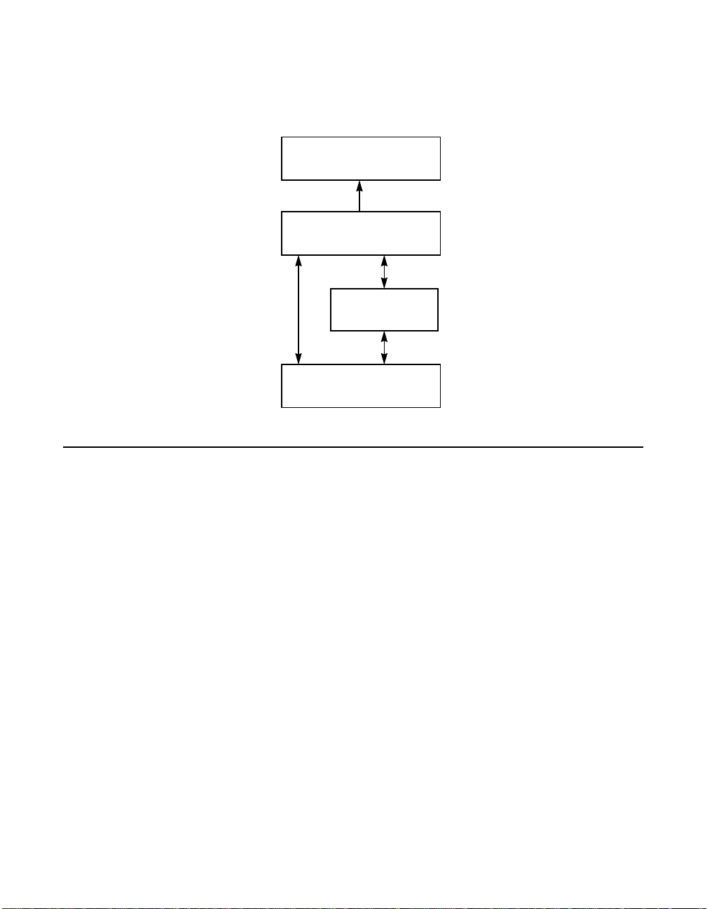
1.2 Overview
Figure 1.1 illustrates the format of the LSI Logic SDMS software.
Figure 1.1 The LSI Logic SDMS Software
.
Operating System
Supports
SDMS Storage Device Driver
SDMS Storage BIOS
Supports
LSI Logic Controller or
Processor
An LSI Logic SCSI controller or processor can control peripherals such
as hard disk drives, CD-ROM drives, tape drives, scanners, and
removable media. You can connect up to 15 wide (16-bit) SCSI
peripheral devices or seven 8-bit SCSI peripheral devices (by using the
SCSI bus) to a SCSI host adapter on which the SCSI controller or
processor resides.
1-2 Using the SDMS Software
Copyright © 1993–2001 by LSI Logic Corporation. All rights reserved.
Page 21
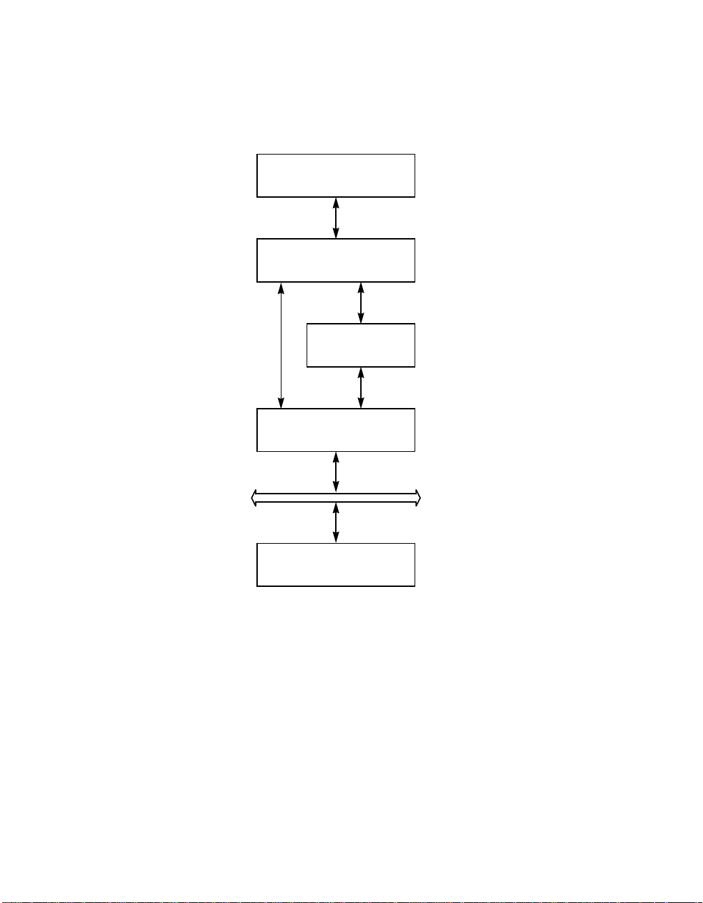
Figure 1.2 illustrates the flow of SDMS information within an operating
system.
Figure 1.2 SDMS Information Flow
.
Operating System
SDMS Storage Driver
SDMS Storage BIOS
LSI Logic Controller or
Processor
SCSI Bus
SCSI Peripherals
Overview 1-3
Copyright © 1993–2001 by LSI Logic Corporation. All rights reserved.
Page 22

1.3 SDMS Device Drivers
The SDMS device drivers translate an operating system I/O request into
a SCSI request. Each SDMS SCSI device driver is operating system
specific and is designed to work on standard LSI Logic chip
implementations.
Currently, LSI Logic provides PCI to SCSI device drivers for the following
operating systems:
• MS-DOS 6.0/Windows 3.1X
• Windows 95, Windows 98, and Windows Me (Millennium Edition)
• Windows NT - 4.0
• Windows 2000
• OS/2 - 4.XX
• SCO OpenServer - Release 5.XX
• UnixWare - 7
• Solaris - 7 and 8
• Linux
• NetWare - 4.XX and 5.XX (NWPA)
This user’s guide provides device driver installation and configuration
instructions for each of these operating systems.
1.4 Basic Guidelines
Some basic rules for using SDMS software and installing a SCSI host
adapter device follow. The SDMS software requires an IBM PC/AT or
compatible computer with an 80486 or higher microprocessor. An
understanding of basic operating system commands is assumed. In
addition, users of this manual should have a general knowledge of the
SCSI standard.
Before using the SDMS software, you should configure the SCSI
controller into your system, taking into account the configuration of other
host adapters and system resources.
1-4 Using the SDMS Software
Copyright © 1993–2001 by LSI Logic Corporation. All rights reserved.
Page 23

LSI Logic recommends that you back up all data before making any
changes or installing any software, including LSI Logic SCSI controllers
and software. Failure to adhere to this accepted computer practice may
lead to loss of data. You must terminate both ends of the SCSI bus.
Refer to the hardware manuals for the devices and users’ guides for the
host adapters to properly terminate the bus. Also you should locate
where jumpers or dip switches are for setting SCSI ID numbers. Usually,
the host adapter is ID 7. The devices are then set at IDs 0 through 6
(plus 8 through 15 for Wide SCSI). The bootable hard drive must have
the lowest numerical SCSI ID, unless you are able to use the BIOS Boot
Specification (BBS). Refer to Chapter 2 for additional information
regarding the BBS.
The red or blue line on a standard SCSI cable (or the black line on one
end of a multicolored SCSI cable) designates pin 1 on the cable
connector and must connect to pin 1 on the device and host adapter
connector. Refer to the hardware manuals for the devices and the
controller to locate pin 1 of the connector.
If the system already has an internal bootable hard drive (IDE, ESDI, or
ST506), the drivers for the SCSI device(s) must reside on the internal
bootable drive.
Basic Guidelines 1-5
Copyright © 1993–2001 by LSI Logic Corporation. All rights reserved.
Page 24

1-6 Using the SDMS Software
Copyright © 1993–2001 by LSI Logic Corporation. All rights reserved.
Page 25

Chapter 2
SCSI BIOS and
Configuration Utility
This chapter describes the SDMS SCSI BIOS and Configuration Utility.
It includes these topics:
• Section 2.1, “Introduction,” page 2-1
• Section 2.2, “Boot Initialization with BBS,” page 2-3
• Section 2.3, “Using the SCSI BIOS Configuration Utility,” page 2-3
• Section 2.4, “Starting the SCSI BIOS Configuration Utility,” page 2-4
• Section 2.5, “Exiting the SCSI BIOS Configuration Utility,” page 2-22
2.1 Introduction
The SDMS SCSI BIOS is the bootable ROM code that manages SCSI
hardware resources. Itis specific to a family of LSI Logic SCSI controllers
or processors. The SDMS SCSI BIOS integrates with a standard system
BIOS, extending the standard disk service routine provided through
INT13h.
During the boot time initialization, the SCSI BIOS determines if there are
other hard disks, such as an IDE drive, already installed by the system
BIOS. If there are, the SCSI BIOS maps any SCSI drives it finds behind
the drive(s) already installed. Otherwise, the SCSI BIOS installs drives
starting with the system boot drive. In this case, the system boots from
a drive controlled by the SCSI BIOS. For version 4.05.00 and higher,
LSI Logic supports the BIOS Boot Specification (BBS).
The next section, “Boot Initialization with BBS,” discusses selecting boot
and drive order.
PCI Storage Device Management System SDMS 4.0 User’s Guide 2-1
Copyright © 1993–2001 by LSI Logic Corporation. All rights reserved.
Page 26

2.1.1 Features
The SDMS SCSI BIOS supports these features:
• Configuration for up to 256 adapters-any 4 can be chosen for INT13h
(boot ROM) support
• All LSI53C8XX devices including LSI53C895A
• LSI53C1000 and LSI53C1010 devices
• SPI-3 Parallel Protocol Request (PPR)
• Domain Validation
2.1.2 LSI Logic Devices Supported
All LSI Logic devices and host adapters have undergone a name change.
They have transitioned from a SYM prefix to an LSI prefix. The SDMS
SCSI BIOS supports the following devices and their associated LSI Logic
host adapters:
• LSI53C810, LSI53C810A, LSI53C810AE (LSI8100S, LSI8100ASP,
LSI20810)
• LSI53C815 (LSI815XS, LSI8150SP)
• LSI53C825, LSI53C825A (LSI8250S, LSI8251S, LSI8251D,
LSI8250ASP, LSI8251ASP, LSI8251AD)
• LSI53C860, LSI53C860AE (LSI8600SP, LSI20860)
• LSI53C875, LSI53C875E (LSI8750SP, LSI8751SP, LSI8751SPE,
LSI8751D)
• LSI53C876 (LSI22801, LSI22802)
• LSI53C885
• LSI53C895 (LSI8951U, LSI8952U)
• LSI53C895A (LSI8953U)
• LSI53C896 (LSI22910, LSI21002, LSI22902)
• LSI53C1000 (LSI20160, LSI20160L)
• LSI53C1010 (ITI6200U3LP, LSI22915A, LSI21040, LSI22903,
LSI21003)
2-2 SCSI BIOS and Configuration Utility
Copyright © 1993–2001 by LSI Logic Corporation. All rights reserved.
Page 27

2.2 Boot Initialization with BBS
The SDMS SCSI BIOS provides support for the BBS, which allows you
to choose which device to boot from by selecting the priority.
To use this feature, the system BIOS must also be compatible with the
BBS. If your system supports the BBS, then use the system BIOS setup
menu to select the boot and drive order. In the system BIOS setup, the
Boot Connection Devices menu appears with a list of available boot
options. Use that menu to select the device and rearrange the order.
Then exit saving changes to continue the boot process.
2.2.1 CD-ROM Boot Initialization
The SCSI BIOS supports boot initialization from a CD-ROM drive. The
five types of emulation are:
• No emulation disk
• Floppy 1.2 Mbyte emulation disk
• Floppy 1.44 Mbyte emulation disk
• Floppy 2.88 Mbyte emulation disk
• Hard disk emulation
The type of emulation determines the drive letter assignment for the
CD-ROM. For example, if you load a 1.44 Mbyte floppy emulation
CD-ROM, then the CD-ROM drive would become the designated A:
drive, and the existing floppy would become drive B:.
2.3 Using the SCSI BIOS Configuration Utility
This section provides the menu formats and user inputs available to
inform all users about this utility prior to running it. All SCSI BIOS
Configuration Utility screens that display various menus are partitioned
into fixed areas. This area provides static general help text information.
Boot Initialization with BBS 2-3
Copyright © 1993–2001 by LSI Logic Corporation. All rights reserved.
Page 28

2.3.1 User Inputs
You make configuration changes in the main area of the menu. As in the
example menus, it is lighter in color than the header or footer areas.
Table 2.1 lists the various keyboard options you use to make changes.
Settings with grey or yellow text can be changed, settings with white text
cannot. This is true regardless of the Color/Mono setting chosen.
Table 2.1 Keyboard Options
Keyboard Options Description
F1 = Help Provides context sensitive help for the cursor
F2 = menu Sets cursor context to the menu Area. Select a
Arrow Keys = Select
Item
+/− = Change [Item] Changes items with values in [ ] brackets. Use the
Esc = Abort/Exit Aborts the current context operation and/or exits the
Home/End = Select Item Moves the cursor to the start/end of a scrollable
Enter = Execute <Item> Executes options with values in < > brackets. Press
resident field.
menu item and press Enter. This option is only
available from the Main menu.
Move the cursor up, down, left, or right.
‘+’ and ‘−’ keys in the top row of the main keyboard
or use the numerickeypad‘+’ and ‘−’ keys to change
values. When pressed, theytoggle a modifiable field
to its next relative value. ‘+’ toggles the value up and
‘−’ toggles the value down.
current screen. This option calls an Exit menu,
described further in Section 2.5, “Exiting the SCSI
BIOS Configuration Utility,” page 2-22.
field.
Enter to execute the field’s associated function.
2.4 Starting the SCSI BIOS Configuration Utility
If you have SCSI BIOS version 4.XX, and it includes the SDMS SCSI
BIOS Configuration Utility, you can change the default configuration of
your SCSI host adapters. You may decide to alter these default values if
2-4 SCSI BIOS and Configuration Utility
Copyright © 1993–2001 by LSI Logic Corporation. All rights reserved.
Page 29

there is a conflict between device settings or if you need to optimize
system performance.
You can see the version number of your SCSI BIOS in a banner
displayed on your computer monitor during boot. If the utility is available,
the following message also appears on your monitor:
Press Ctrl-C to start LSI Logic Configuration Utility...
This message remains on your screen for about five seconds, giving you
time to start the utility. If you decide to press Ctrl-C, the message
changes to:
Please wait invoking LSI Logic Configuration Utility...
After a brief pause, your computer monitor displays the Main menu of the
SCSI BIOS Configuration Utility.
The following messages may appear during the boot process:
• Adapter removed from boot order, parameters will be updated
accordingly! appears when an adapteris removed from the system
or relocated behind a PCI bridge.
• Configuration data invalid, saving default configuration!
appears if none of the information in NonVolatile Random Access
Memory (NVRAM) is valid.
• Found SCSI Controller not in following Boot Order List, to
Add: Press Ctrl-C to start LSI Logic Configuration
Utility... or Adapter configuration may have changed,
reconfiguration is suggested! could appear when fewerthan four
adapters are in the boot order and adapters exist in the system which
are not in the boot order.
The SDMS SCSI BIOS does not control all devices detected by this
configuration utility. Devices such as tape drives and scanners require
that a device driver specific to that peripheral be loaded.
To make changes with this menu-driven utility, one or more LSI Logic
SCSI host adapters must have NVRAM to store the changes. You can
change four sets of configurations. You make changes on subordinate
menus called from the Main menu, which is opened when you start the
SCSI BIOS Configuration Utility. The subordinate menus are:
Starting the SCSI BIOS Configuration Utility 2-5
Copyright © 1993–2001 by LSI Logic Corporation. All rights reserved.
Page 30

• Adapter Properties
• Device Properties
• Boot Adapter List
• Global Properties
All of these properties are controlled by menus you access through the
SCSI BIOS Configuration Utility’s Main menu. The Main menu also gives
an overview of some properties of installed LSI Logic host adapter
boards.
Important: The SCSI BIOS Configuration Utility is a powerful tool.
While using it, if you somehow disable all of your
controllers, press Ctrl-A (or Ctrl-E on version 4.04 or
later) after memory initialization during reboot. This will
allow you to re-enable and reconfigure your controllers.
Also, if the system locks up due to NonVolatile Storage
(NVS), press Ctrl-N to bypass the BIOS in order to
reflash the card.
2.4.1 Accessing the Configuration Utility Main Menu
After invoking the SCSI BIOS Configuration Utility, the Main menu
appears and displays a list of up to 256 PCI to SCSI host adapters in
the system and information about each of them. To select an adapter,
use only the arrow keys and enter key. The system scans the adapter’s
SCSI bus after selecting an adapter.
Only adapters with LSI LogicControl enabled canbe accessed. Adapters
without NonVolatile Memory (NVM) display default settings and cannot
be changed. Figure 2.1 illustrates this menu.
2-6 SCSI BIOS and Configuration Utility
Copyright © 1993–2001 by LSI Logic Corporation. All rights reserved.
Page 31

Figure 2.1 Main Menu
LSI Logic SDMS (TM) PCI SCSI Configuration Utility Version PCI-4.XX.00
<Boot Adapter List> <Global Properties>
LSI53C8XX Host Bus Adapters
Adapter PCI
Bus
Dev/
Func
Port
Number
IRQ NVM Boot
Order
LSI Logic
Control
<53C1010-66 0 60> E400 9 Yes 1 Enabled
<53C1010-66 0 61> E000 10 Yes 0 Enabled
<53C895 0 58> FC00 11 Yes 2 Enabled
F1 =Help ΑrrowKeys=Select Item -/+ =Change [Item]
Esc=Abort/Exit Home/End =Select Item Enter=Execute <Item>
F2 =Menu
Starting the SCSI BIOS Configuration Utility 2-7
Copyright © 1993–2001 by LSI Logic Corporation. All rights reserved.
Page 32

Table 2.2 lists the fields on this menu and their descriptions.
Table 2.2 Main Menu Fields and Descriptions
Fields
Adapter Information Indicates the specific LSI Logic family of host adapters. Clicking on an
PCI Bus Information Indicates the PCI bus number (range0x00–0xFF, 0–255 decimal) assigned
Dev/Func Information Indicates the PCI Device/Function assigned by the system BIOS to an
Port
Number
IRQ Information Indicates the Interrupt Request Line used by an adapter, which is assigned
NVM Information Indicates whether an adapter has NVM associated with it. An adapter's
Boot Order Information Indicates the relative boot order (0 to 3) of an adapter. The SDMS SCSI
LSI Logic
Control
Field Type
[Value] Descriptions
entry under Adapter will lead to the Adapter Properties menu.
by the system BIOS to an adapter.
adapter.
An 8-bit value is mapped as follows:
Bit#76543210
Bits [7:3]: Device (range 0x00–0x1F, 0–31 decimal)
Bits [2:0]: Function (range [0–7])
Information Indicates the I/O port number that communicates with an adapter, which
the system BIOS assigns.
by the system BIOS.
configuration is stored in its associated NVM. NVM can refer to NVRAM
that is resident on a host adapter or to system NVS.
BIOS traverses up to four adapters in the specified order in search of
bootable media. To modify this field, access the Boot Adapter List menu.
Information Indicates whether an adapter is eligible for LSI Logic software control or is
reserved for control by non-LSI Logic software.
Below the header area of the Main menu, the Boot Adapter List and
Global Properties options are available for you to configure their host
adapters. The Boot Adapter List allows selection and ordering of boot
adapters. Global Properties allow changes to global scope settings.
Refer to Section 2.4.4, “Boot Adapter List Menu,” page 2-17 and Section
2.4.5, “Global Properties Menu,” page 2-20 for more detailed information.
2-8 SCSI BIOS and Configuration Utility
Copyright © 1993–2001 by LSI Logic Corporation. All rights reserved.
Page 33

2.4.2 Adapter Properties Menu
The Adapter Properties menu allows you to view and modify adapter
settings and SCSI devices connected to it. It also provides access to an
adapter's device settings. To display this menu, select a device under
Adapter field on the Main menu and press Enter. Figure 2.2 illustrates the
Adapter Properties menu.
Figure 2.2 Adapter Properties Menu
LSI Logic SDMS (TM) PCI SCSI Configuration Utility Version PCI-4.XX.00
Adapter Properties
Adapter PCI Dev/
Bus Func
53C895
0
60
<Device Properties>
SCSI Parity [Yes]
Host SCSI ID [7]
SCSI Bus Scan Order [Low to High (0..Max)]
Removable Media Support [None]
CHS Mapping [SCSI Plug and Play Mapping]
Spinup Delay (Secs) [2]
Secondary Cluster
[No]
Server
Termination Control [Auto]
<Restore Defaults>
F1 =Help ΑrrowKeys=Select Item -/+ =Change [Item]
Esc=Abort/Exit Home/End =Select Item Enter=Execute <Item>
Starting the SCSI BIOS Configuration Utility 2-9
Copyright © 1993–2001 by LSI Logic Corporation. All rights reserved.
Page 34

Table 2.3 lists the fields on this menu and their descriptions.
Note: If the field displays in grey or yellow text it is available for
changes. If it displays in white text it is not available.
Table 2.3 Adapter Properties Menu Fields and Descriptions
Field Field Type
Device
Properties
SCSI Parity Configuration
Host SCSI ID Configuration
SCSI Bus
Scan Order
Removable
Media
Support
[Value]
Executable Select this option and press Enter to view and modify device
[Yes/No]
[0 to 7/0 to 15]
Configuration
[Low to High (0
.. Max)/High to
Low (Max .. 0)]
Configuration
[None/Boot
Drive Only/
With Media
Installed]
Descriptions
properties.
Indicates whether SCSI parity is enabled for an adapter. When
disabled, you must disable disconnects for all devices, as parity
checking for the reselection phase is not disabled. If a nonparity
generating device disconnects, its operation will never complete
because the reselection fails due to parity error.
Indicates the SCSI identifier of an adapter. LSI Logic
recommends that this field be set to the highest priority SCSI
identifier, which is 7.
Indicates the order in which to scan SCSI identifiers on an
adapter. Changing this item will affect drive letter assignment(s)
if more than one device is attached to an adapter.
Specifies the removable media support option for an adapter.
Removable media support only applies to devices that report
themselves as a hard drive. It does not apply to CD-ROM
devices or Magnetic Optical devices.
None indicates no removable media support whether the drive is
selected as first (BBS), or is first in the scan order (non-BBS).
Boot Drive Only provides removable media support for a
removable hard drive if it is first in the scan order.
With Media Installed provides removable media support
regardless of the drive number assignment. You must have
media in the drive at bootup.
2-10 SCSI BIOS and Configuration Utility
Copyright © 1993–2001 by LSI Logic Corporation. All rights reserved.
Page 35

Table 2.3 Adapter Properties Menu Fields and Descriptions (Cont.)
Field Field Type
[Value]
CHS Mapping Configuration
[SCSI Plug and
Play Mapping/
Alternate CHS
Mapping]
Spinup Delay
(secs)
Secondary
Cluster Server
Configuration
[1 to 15]
Configuration
[Yes/No]
Descriptions
Defines how the Cylinder HeadSector (CHS) values are mapped
onto a disk without pre-existing partition information.
SCSI Plug and Play Mapping automatically determines the most
efficient and compatible mapping.
Alternate CHS Mapping utilizes an alternate, possibly less
efficient mapping that may be required if a device is moved
between adapters from different vendors.
Caution: Neither of these options has any effect after a disk has
been partitioned using the FDISK command. The FDISK utility
is a tool that you can use to delete partition entries, one or all of
them. If all partition entries are deleted, it is necessary to reboot
to clear memory or the old partitioning data will be reused, thus
nullifying the previous operation. Use care to ensure that the
correct disk is the target of an FDISK command.
Indicates the delay in seconds between spinups of devices
attached to an adapter. Staggered spinups balance the total
electrical current load on the system during boot. The default
value is 2 seconds.
Indicates whether an adapter has one or more devices attached
that are shared with one or more other adapters. Therefore, the
SDMS SCSI BIOS should avoid SCSI bus resets as much as
possible.
This option allows you to enable an adapter to join a cluster of
adapters without doing any SCSI bus resets. This is a
requirement for the Microsoft Cluster Server. The default value is
No with an alternate option of Yes.
Termination
Control
Restore
Defaults
Configuration
[Auto/Off]
If available, the field Indicates whether an adapter has automatic
termination control. If not available, its current status is either
Auto or Off.
Auto means that the adapter automatically can determine
whether it should enable or disable its termination.
Off means termination on the adapter is off and the devices at
the ends of the SCSI bus must terminate the bus.
Executable Press Enter to obtain default settings.
Starting the SCSI BIOS Configuration Utility 2-11
Copyright © 1993–2001 by LSI Logic Corporation. All rights reserved.
Page 36

2.4.3 Device Properties Menu
The Device Properties menu allows you to view and update individual
device settings for an adapter. Changing a setting for the host device (for
example, SCSI ID 7) changes the setting for all devices. The number of
fields displayed requires the menu to scroll left/right in order to display
the information. When accessing this menu online, use the Home/End
keys to scroll to columns currently not displayed. The scroll indicator on
the bottom of the menu shows where the cursor is relative to the first and
last columns. The example for the Device Properties menu is split
(Figure 2.3 and Figure 2.4) due to the width of its multiple fields/columns.
2-12 SCSI BIOS and Configuration Utility
Copyright © 1993–2001 by LSI Logic Corporation. All rights reserved.
Page 37

Figure 2.3 Device Properties Menu (Left Half)
LSI Logic SDMS (TM) PCI SCSI Configuration Utility Version PCI-4.XX.00
Device Properties
SCSIIDDevice Identifier MB/Sec MT/Sec Data
Width
Scan
ID
Scan
LUNs>0
Dis-
connect
0 Quantum Viking 4.5 [160] [80] [16] [Yes] [Yes] [On]
1 Quantum Viking 4.5 [160] [80] [16] [Yes] [Yes] [On]
2 Quantum Viking 4.5 [160] [80] [16] [Yes] [Yes] [On]
3 Quantum Viking 4.5 [160] [80] [16] [Yes] [Yes] [On]
4 Quantum Viking 4.5 [160] [80] [16] [Yes] [Yes] [On]
5 Quantum Viking 4.5 [160] [80] [16] [Yes] [Yes] [On]
6 - [160] [80] [16] [Yes] [Yes] [On]
7 53C895 [160] [80] [16] [Yes] [Yes] [On]
8 - [160] [80] [16] [Yes] [Yes] [On]
9 - [160] [80] [16] [Yes] [Yes] [On]
10 - [160] [80] [16] [Yes] [Yes] [On]
11 - [160] [80] [16] [Yes] [Yes] [On]
12 - [160] [80] [16] [Yes] [Yes] [On]
13 - [160] [80] [16] [Yes] [Yes] [On]
14 - [160] [80] [16] [Yes] [Yes] [On]
15 - [160] [80] [16] [Yes] [Yes] [On]
F1 =Help ArrowKeys=Select Item -/+ =Change [Item]
Esc=Abort/Exit Home/End =Select Item Enter=Execute <Item>
Starting the SCSI BIOS Configuration Utility 2-13
Copyright © 1993–2001 by LSI Logic Corporation. All rights reserved.
Page 38

Figure 2.4 Device Properties Menu (Right Half)
LSI Logic SDMS (TM) PCI SCSI Configuration Utility Version PCI-4.XX.00
Device Properties
SCSIIDDevice Identifier SCSI
Timeout
Queue
Tags
Boot
Choice
Format Verify Restore
Defaults
0 Quantum Viking 4.5 < 10> [On] [No] [Format] [Verify] <Defaults>
1 Quantum Viking 4.5 < 10> [On] [No] [Format] [Verify] <Defaults>
2 Quantum Viking 4.5 < 10> [On] [No] [Format] [Verify] <Defaults>
3 Quantum Viking 4.5 < 10> [On] [No] [Format] [Verify] <Defaults>
4 Quantum Viking 4.5 < 10> [On] [No] [Format] [Verify] <Defaults>
5 Quantum Viking 4.5 < 10> [On] [No] [Format] [Verify] <Defaults>
6 - < 10> [On] [No] [Format] [Verify] <Defaults>
7 53C895 < 10> [On] [No] [Format] [Verify] <Defaults>
8 - < 10> [On] [No] [Format] [Verify] <Defaults>
9 - < 10> [On] [No] [Format] [Verify] <Defaults>
10 - < 10> [On] [No] [Format] [Verify] <Defaults>
11 - < 10> [On] [No] [Format] [Verify] <Defaults>
12 - < 10> [On] [No] [Format] [Verify] <Defaults>
13 - < 10> [On] [No] [Format] [Verify] <Defaults>
14 - < 10> [On] [No] [Format] [Verify] <Defaults>
15 - < 10> [On] [No] [Format] [Verify] <Defaults>
F1 =Help ArrowKeys=Select Item -/+ =Change [Item]
Esc=Abort/Exit Home/End =Select Item Enter=Execute <Item>
2-14 SCSI BIOS and Configuration Utility
Copyright © 1993–2001 by LSI Logic Corporation. All rights reserved.
Page 39

Table 2.4 lists the fields on this menu and their descriptions.
Table 2.4 Device Properties Menu Fields and Descriptions
Field Field Type
Description
[Value]
SCSI ID Information Displays the device’s SCSI identifier.
Device
Identifier
MB/Sec Information
MT/Sec Configuration
Data Width Configuration
Scan ID Configuration
Information Indicates the ASCII device identifier string, as extracted from the
device’s inquiry data.
Indicates the maximum synchronous data transfer rate of the
[0/5/10/20/40/
80/160]
adapter in megabytes per second corresponding to the width and
transfer rate settings that follow.
Indicates the maximum synchronous data transfer rate of the
[0/5/10/20/40/
80]
adapter in megatransfers per second. Can be changed to a lower
transfer rate.
Displays the maximum data width of the adapter in bits. Can be
[8/16]
changed to narrower, if available.
Indicates whether to scan for this SCSI identifier at boot time.
[Yes/No]
Utilizing this setting allows you to ignore a device. This decreases
boot time by disabling inquiry of unused SCSI identifiers.
Set this option to No if there is a device that you do not want to
be available to the system. Also, on a bus with only a few devices
attached, you can speed up boot time by changing this setting to
No for all unused SCSI IDs.
Scan LUNs > 0 Configuration
[Yes/No]
Indicates whether to scan for Logical Unit Numbers(LUNs) greater
than zero for a device. LUN 0 is always queried. Use this option if
a multi-LUN device responds to unoccupied LUNs or if it is desired
to reduce the visibility of a multi-LUN device to LUN 0 only.
Disconnect Configuration
[On/Off]
Starting the SCSI BIOS Configuration Utility 2-15
Copyright © 1993–2001 by LSI Logic Corporation. All rights reserved.
Set this option to No if you have problems with a device that
responds to all LUNs whether they are occupied or not. Also, if a
SCSI device with multiple LUNs exists on your system but you do
not want all of those LUNs to be available to the system, then set
this option to No. This will limit the scan to LUN 0.
Indicates whether to allow a device to disconnect during SCSI
operations. Some (usually newer) devices run faster with
disconnect enabled, while some (usually older) devices run faster
with disconnect disabled.
Page 40

Table 2.4 Device Properties Menu Fields and Descriptions (Cont.)
Field Field Type
Description
[Value]
SCSI Timeout Executable
[0–9999]
Indicates the maximum allowable time for completion of a SCSI
operation in seconds. Since timeouts provide a safeguard that
allows the system to recover should an operation fail, LSI Logic
recommends that a value greater than zero be used. A value of
zero allows unlimited time for an operation to complete and could
result in the system hanging (waiting forever) should an operation
fail.
Note: This field is executable and must be selected with the Enter
key. Youalso input the new value with the number keys from either
the keyboard or number pad.
Queue Tags Configuration
[On/Off]
Indicates whether to allow the use of queue tags for a device.
Currently the BIOS does not use queue tags. This item specifies
queue tag control to higher level device drivers.
Boot Choice Configuration
[Yes/No]
Indicates whether this device can be selected as the boot device.
This option is only applicable to devices attached to adapter
number zero in the boot list on non-BBS systems. It provides
primitive BBS flexibility to non-BBS systems.
Format Executable Allows low-level formatting on a disk drive, if enabled. Low-level
formatting will completely and irreversibly erase all data on the
drive. To low level format a device, select the device from the
menu and use the arrow keys to move the cursor to the Format
column. Press Enter.
Note: Formatting will default the drive to a 512-byte sector size
even if the drive had previously been formatted to another sector
size.
Verify Executable Allows verification of all sectors on a device and reassigns
defective Logical Block Addresses (LBAs), if enabled. To verify all
sectors, select the device from the menu and use the arrow keys
to move the cursor to the Verify column. Press Enter.
Restore
Executable Press Enter to obtain default settings.
Defaults
2-16 SCSI BIOS and Configuration Utility
Copyright © 1993–2001 by LSI Logic Corporation. All rights reserved.
Page 41

2.4.4 Boot Adapter List Menu
The Boot Adapter List menu specifies the order in which adapters boot
when more than one LSI Logic host adapter is in a system. Up to four
of the total adapters in a system can be selected as bootable. To control
a Boot Volume, only one of the four “active” controllers can be used.
To select this menu:
1. Press F2 while on the Main menu to move the cursor to the menu
Area.
2. Move the cursor to Boot Adapter List with the arrow keys.
3. Press Enter.
Adapters can be added or deleted using this menu. To add an adapter
to the boot list, press the Insert key while on the Boot Adapter List. Use
the arrow keys to select the desired adapter and press Enter to add it to
the end of the Boot Adapter List.
To remove an adapter from the boot list, press the Delete key while on
the desired adapter in the Boot Adapter List. You can also change the
boot order by using the “+” or “−” keys. For example, place the cursor on
the adapter that you want to change, and use the “+” or “−” key to raise
or lower the boot order.
Starting the SCSI BIOS Configuration Utility 2-17
Copyright © 1993–2001 by LSI Logic Corporation. All rights reserved.
Page 42

Figure 2.5 illustrates the Boot Adapter List menu.
Figure 2.5 Boot Adapter List Menu
LSI Logic SDMS (TM) PCI SCSI Configuration Utility Version PCI-4.XX.00
Boot Adapter List
Insert=Add an adapter Delete=Remove an adapter
Adapter PCI
Bus
Dev/
Func
Boot
Order
Current
Status
Next
Boot
53C895 0 98 [2] Off [On]
53C1010-66 0 60 [0] On [On]
53C1010-66 0 61 [1] On [On]
Hit Insert to select an adapter from this list.
<53C895 0 98>
<53C1010-66 0 60>
<53C1010-66 0 61>
F1=Help ArrowKeys=Select Item -/+ =Change [Item]
Esc=Abort/Exit Home/End =Select Item Enter=Execute <Item>
2-18 SCSI BIOS and Configuration Utility
Copyright © 1993–2001 by LSI Logic Corporation. All rights reserved.
Page 43

Table 2.5 lists the fields on this menu and their descriptions.
Table 2.5 Boot Adapter List Menu Fields and Descriptions
Field Field Type
Description
[Value]
Adapter Information Indicates the specific LSI Logic family of host adapters.
PCI Bus Information Indicates the PCI bus number (range 0x00–0xFF, 0–255 decimal)
assigned by the system BIOS to an adapter.
Dev/Func Information Indicates the PCI Device/Function assigned by the system BIOS to an
adapter.
An 8-bit value is mapped as follows:
Bit#76543210
Bits [7:3]: Device (range 0x00–0x1F, 0–31 decimal)
Bits [2:0]: Function (range 0–7)
BootOrder Configuration
[0 to 3]
Indicates the relative boot order (0 to 3) of the listed adapter. The SDMS
SCSI BIOS traverses up to four adapters in the specified order in search
of bootable media.
Current
Status
Information Indicates whether an adapter in the boot list was enabled during the most
recent boot. The SDMS SCSI BIOS ignores disabled adapters and their
attached devices, although they are still visible to the configuration utility.
Next Boot Configuration
[On/Off]
Indicates whether to enable an adapter upon the next boot. The SDMS
SCSI BIOS ignores disabled adapters and their attached devices
although they are still visible to the configuration utility.
Starting the SCSI BIOS Configuration Utility 2-19
Copyright © 1993–2001 by LSI Logic Corporation. All rights reserved.
Page 44

2.4.5 Global Properties Menu
The Global Properties menu allows you to view boot information and to
set display and video modes. Figure 2.6 illustrates the Global Properties
menu. Table 2.6 lists the fields and their descriptions.
Figure 2.6 Global Properties Menu
LSI Logic SDMS (TM) PCI SCSI Configuration Utility Version PCI-4.XX.00
Global Properties
Pause When Boot Alert
[No]
Displayed
Boot Information Display
[Verbose]
Mode
Negotiate with devices [Supported]
Language [English]
Video Mode [Color]
Support Interrupt [Hook Interrupt, the Default]
<Restore Defaults>
F1 =Help ArrowKeys=Select Item -/+ =Change [Item]
Esc=Abort/Exit Home/End=Select Item Enter=Execute <Item>
2-20 SCSI BIOS and Configuration Utility
Copyright © 1993–2001 by LSI Logic Corporation. All rights reserved.
Page 45

Table 2.6 Global Properties Fields and Descriptions
Field Field Type
Description
[Value]
Pause When Boot
Alert Displayed
Configuration
[Yes/No]
Specifies a pause during the boot for user
acknowledgement. The pause occurs after displaying
an alert message.
To continue after displaying a message, specify No.
To wait for any key after displaying a message, specify
Yes.
Boot Information
Display Mode
Configuration
[Terse/Verbose]
Specifies how much BIOS information displays during
boot.
To display minimum information, specify Terse mode.
To display detailed information, specify Verbose mode.
Negotiate with
Devices
Configuration
[All, None, Supported]
Sets the default value for synchronous and wide
negotiations with specified devices.
Language Configuration This option specifies the current language set for using
this utility.
Video Mode Configuration
[Color/Monochrome]
Specifies the default video mode for the SCSI BIOS
Configuration Utility. The monochrome setting
enhances readability on a monochrome monitor.
Support Interrupt Configuration for BBS
Systems
[Hook Interrupt, the
This option allows the ability to prevent a hook on
INT40h, if required. The two settings are: Hook
Interrupt, the default, and Bypass Interrupt Hook.
default/Bypass
Interrupt Hook]
Hook Interrupt is the normal operation that supports
booting CD-ROMs in floppy emulation mode on most
Fixed for non-BBS
machines.
systems
On certain platforms, the system BIOS uses the
INT40h interrupt chain in a nonstandard way. On these
platforms, you should use the "Bypass Interrupt Hook"
setting. This setting prevents a hook into the INT40h
chain. If the "Bypass Interrupt Hook" setting is used on
systems that do not require it, the CD-ROM may fail to
boot and an error message may appear and indicate it
is unable to read the boot device.
Note:Try toggling this value if your machine fails to
boot a CD-ROM in floppy emulation mode.
Restore Defaults Executable Press Enter to obtain default settings.
Starting the SCSI BIOS Configuration Utility 2-21
Copyright © 1993–2001 by LSI Logic Corporation. All rights reserved.
Page 46

2.5 Exiting the SCSI BIOS Configuration Utility
The Exit menu for the SCSI BIOS Configuration Utility is used for all five
of the menus listed above. However, the available functionality is different
for the Main menu and the four subordinate menus. Figure 2.7 illustrates
the Exit menu.
Figure 2.7 Exit Menu
LSI Logic SDMS (TM) PCI SCSI Configuration Utility Version PCI-4.XX.00
Adapter and/or device property changes have been made
<Cancel exit>
Exit the Configuration Utility
<Save changes then exit this menu>
<Discard changes then exit this menu>
To exitfrom the AdapterProperties, Device Properties, Boot Adapter List,
or Global Properties menus, use these exit options:
Cancel exit This option returns you to the previous menu.
Save changes then
exit this menu
Discard changes then
exit this menu
This option implements any changes you made on the
previous menu and returns you to the Main menu.
This option restores the default settings and returns you
to the Main menu.
To exit from the Main menu, use these exit options:
Cancel exit This returns you to the Main menu.
Exit the Configuration
Utility
This option exits the configuration and automatically
reboots your system.
Important: If you reboot the system without properly exiting from this
utility, some changes may not take effect.
2-22 SCSI BIOS and Configuration Utility
Copyright © 1993–2001 by LSI Logic Corporation. All rights reserved.
Page 47

Chapter 3
Windows 95, Windows
98, Windows Me Device
Driver Installation
This chapter describes the device drivers for the Windows 95, Windows
98, and Windows Me operating systems. It provides installation
instructions for new and existing system installations and includes these
topics:
• Section 3.1, “Introduction,” page 3-1
• Section 3.2, “Using the SYMC8XX/SYM_HI/SYM_U3 Drivers,”
page 3-4
• Section 3.3, “Installing Drivers for Windows 95/98/Me,” page 3-5
• Section 3.4, “Troubleshooting,” page 3-13
• Section 3.5, “Using the Command Line Options,” page 3-14
• Section 3.6, “Using SCSI Tools for Windows 95/98,” page 3-20
3.1 Introduction
Windows 95, Windows 98, and Windows Millennium Edition (Me) are
operating systems designed to run on Intel processors using current
technology. This chapter refers to Windows 95, Windows 98, and
Windows Me as Windows 95/98/Me in many instances.
Windows 95/98/Me provides a graphical user interface (GUI)
environment incorporating many high-level features. Refer to the
Microsoft Windows 95/98/Me documentation for more details. An I/O
manager handles I/O requests by going through the appropriate drivers
to address a SCSI peripheral.
Windows 95/98/Me provides class drivers for hard disk, floptical,
CD-ROM, printer, and scanner peripherals. Other class drivers, provided
by peripheral manufacturers, are added to support new devices.
Microsoft provides the port driver and LSI Logic provides the miniport
drivers, which are called SYMC8XX.MPD, SYM_HI.MPD, and SYM_U3.MPD.
PCI Storage Device Management System SDMS 4.0 User’s Guide 3-1
Copyright © 1993–2001 by LSI Logic Corporation. All rights reserved.
Page 48

3.1.1 Features
These drivers complete the path to an LSI Logic controller or processor
with an optional SDMS SCSI BIOS.
LSI Logic uses the same filenames for their drivers for different Windows
operating systems. The driver files are packaged either in separate
subdirectories based on the Windows operating system or on different
flex disks. To determine the driver file for Windows 95/98/Me, note that
the filename ends with .MPD. The following sections describe these
drivers and their installation.
The SDMS device drivers for Windows 95/98/Me support these features:
• Ultra160 data transfers (for LSI53C1000 and LSI53C1010)
• Domain Validation (for the SYM_U3.MPD driver only)
• Parallel Protocol Request (PPR) (for the SYM_U3.MPD driver only)
• Cyclic Redundancy Check (CRC) (for the SYM_U3.MPD driver only)
• Synchronous negotiation (including Fast SCSI, Ultra SCSI, Ultra2 SCSI)
• Wide negotiation
• Auto Request Sense
• Multiple host adapters
• Multiple LUNs
• Disconnect/Reselect
• Scatter/Gather
• Differential support
• SCSI pass-through functionality
• SCSI Configured AutoMatically (SCAM)
• Target Initiated Negotiation (TIN)
• NVRAM (wide/sync parameters, SCSI Host ID, SCAM on/off)
3.1.2 LSI Logic Devices Supported
All LSI Logic devices and host adapters have undergone a name change.
They have transitioned from a SYM prefix to an LSI prefix. No name
changes have occurred for the SDMS Windows 95/98/Me drivers.
3-2 Windows 95, Windows 98, Windows Me Device Driver Installation
Copyright © 1993–2001 by LSI Logic Corporation. All rights reserved.
Page 49

The SYMC8XX.MPD driver supports the following devices and their
associated LSI Logic host adapters:
• LSI53C810, LSI53C810A, LSI53C810AE (LSI8100S, LSI8100ASP,
LSI20810)
• LSI53C815 (LSI815XS, LSI8150SP)
• LSI53C825, LSI53C825A (LSI8250S, LSI8251S, LSI8251D,
LSI8250ASP, LSI8251ASP, LSI8251AD)
• LSI53C860, LSI53C860AE (LSI8600SP, LSI20860)
• LSI53C875, LSI53C875E (LSI8750SP, LSI8751SP, LSI8751SPE,
LSI8751D)
• LSI53C876, LSI53876E (LSI22801, LSI22802)
• LSI53C885
• LSI53C895 (LSI8951U, LSI8952U)
The SYM_HI.MPD driver supports the following devices and their
associated LSI Logic host adapters:
• LSI53C895A (LSI8953U)
• LSI53C896 (LSI22910, LSI21002, LSI22902)
The SYM_U3.MPD driver supports the following devices and their
associated LSI Logic host adapters:
• LSI53C1000 (LSI20160, LSI20160L)
• LSI53C1010 (LSI22915A, LSI22903, LSI21040, LSI21003,
3.1.3 Description
The SYMC8XX.MPD, SYM_HI.MPD , and SYM_U3.MPD drivers conform to the
Microsoft specification for miniport drivers. These drivers allow
connection of SCSI devices including disk drives, CD-ROMs, and tape
drives for PCI-based machines. To support a new SCSI device,
Windows 95/98/Me architecture requires that a class driver for that type
of device bepresent. These are usually supplied by Microsoft, or possibly
by the peripheral manufacturer. No changes to SYMC8XX.MPD,
SYM_HI.MPD ,orSYM_U3.MPD are required. These drivers are only
supported under Windows 95/98/Me.
Introduction 3-3
Copyright © 1993–2001 by LSI Logic Corporation. All rights reserved.
ITI6200U3LP).
Page 50

A Windows application passes SCSI commands directly to the SCSI
devices by using the SCSI pass-through facility. Refer to Microsoft
Windows 95/98/Me documentation for more details. This facility allows
applications to directly control and access SCSI devices by filling in a
data structure and calling into the port driver.
The SYMC8XX.MPD and SYM_HI.MPD drivers support Ultra SCSI protocol,
providing twice the raw data transfer rate of Fast SCSI for disk drives and
LSI Logic host adapters that support Ultra SCSI. These drivers also
support Ultra2 SCSI protocol, providing quadruple the raw data transfer
rate of Fast SCSI.
The SYM_U3.MPD driver supports Ultra160 SCSI protocol providing up to
160 Mbytes/s data transfer for double transition. Ultra160 also includes
CRC, PPR, and Domain Validation. The standard Ultra160 SCSI protocol
performs 80 megatransfers per second resulting in approximately double
the synchronous data transfer rates of Ultra2 SCSI.
Caution: Ultra SCSI requires more stringent SCSI bus cabling
setups than Fast SCSI. Ultra2 SCSI and Ultra160 SCSI
require Low Voltage Differential (LVD) termination.
3.2 Using the SYMC8XX/SYM_HI/SYM_U3 Drivers
The SDMS Software Device Driver and Utilities CD-ROM contains the
SYMC8XX.MPD , SYM_HI.MPD, and SYM_U3.MPD drivers and their associated
files in this directory:
{CD-ROM Drive Letter}:\DRIVERS\WIN9X
You must prepare an SDMS Driver Diskette before proceeding with the
installation instructions.
3.2.1 Preparing an SDMS Driver Diskette
Copy the files listed in this section to the root directory of a clean
diskette. Various subdirectories contain the appropriate driver files. You
will use this SDMS driver diskette during installation.
For the SYMC8XX.MPD driver, locate the files at:
{CD-ROM Drive Letter}:\DRIVERS\WIN9X\8XX9X.
3-4 Windows 95, Windows 98, Windows Me Device Driver Installation
Copyright © 1993–2001 by LSI Logic Corporation. All rights reserved.
Page 51

• SYMC8XX.MPD
• SYMC8XX.INF
For the SYM_HI.MPD driver, locate the files at:
{CD-ROM Drive Letter}:\DRIVERS\WIN9X\WIN9XHI.
• SYM_HI.MPD
• SYM_HI.INF
For the SYM_U3.MPD driver, locate the files at:
{CD-ROM Drive Letter}:\DRIVERS\WIN9X\9XULTRA3
• SYM_U3.MPD
• SYM_U3.INF
You may also obtain the Windows 95/98/Me drivers from the LSI Logic
web site at: http://www.lsilogic.com. After you are connected to this
web site, place your cursor on the Get Drivers option in the menu bar.
Click on the Drivers selection. Choose the Windows 95/98/Me operating
system for SCSI and click on the Go button. Follow the instructions on
subsequent screens to download the drivers.
3.3 Installing Drivers for Windows 95/98/Me
This section provides installation instructions for new and existing
Windows 95/98/Me systems.
3.3.1 New System Installation
Use this procedure to install the SYMC8XX.MPD , SYM_HI.MPD,or
SYM_U3.MPD drivers onto Windows 95/98/Me systems. Windows
95/98/Me automatically adds the driver to the registry and copies the
driver to the appropriate directories. You must install drivers for all host
adapters that are listed as “PCI SCSI Bus Controller.” Installing these
drivers can be done completely before rebooting your system.
Note: A driver bundled in Windows 95, Windows 98, or Windows
Me supports some LSI Logic PCI to SCSI host adapters.
For those adapters, the bundled driver is automatically
Installing Drivers for Windows 95/98/Me 3-5
Copyright © 1993–2001 by LSI Logic Corporation. All rights reserved.
Page 52

installed during Windows Setup. To change to the
SYMC8XX.MPD , SYM_HI.MPD,orSYM_U3.MPD drivers, follow
the instructions in Section 3.3.2, “Existing System
Installation,” after the Windows 95/98/Me installation has
completed.
Follow these instructions for new system installations:
Step 1. Start the Windows 95, Windows 98, or Windows Me Setup
according to the Microsoft instructions.
Step 2. Setup enters the hardware detection phase after a system
reboot.
If the message Symbios™ PCI SCSI Host Adapter appears,
then the bundled driver supports thehost adapter, and it installs
automatically. After the Windows installation has completed,
you can install the SYMC8XX.MPD, SYM_HI.MPD, and/or
SYM_U3.MPD drivers according to the instructions for an
existing system installation
Step 3. If the bundled driver does not support the host adapter, Setup
displays a New Hardware Found - PCI SCSI Bus Controller
dialog box.
Step 4. Select Driver from disk provided by hardware
manufacturer and click OK.
Note: If ASPI8XX.SYS (the SDMS 4.0 DOS ASPI driver) is loaded
when beginning the Windows 95/98/Me installation, no
messages about PCI SCSI Bus Controllers will appear. The
installation completes, but real-mode disk drivers are used.
Refer to Section 3.3.4, “Verifying Correct Driver
Installation,” page 3-11 for more information.
To install the SYMC8XX.MPD , SYM_HI.MPD,orSYM_U3.MPD ,
drivers, (which disable loading of the ASPI8XX.SYS driver
under Windows 95/98/Me) refer to Section 3.3.3, “Existing
System Using ASPI8XX.SYS DOS ASPI Driver,” page 3-10
for installation instructions.
Step 5. Insert the SDMS driver diskette into drive A: (or B:) If using
drive B:, you must select it from the pick list.
Windows 95/98/Me automatically copies the appropriate driver
files and rebuilds its driver database.
3-6 Windows 95, Windows 98, Windows Me Device Driver Installation
Copyright © 1993–2001 by LSI Logic Corporation. All rights reserved.
Page 53

The System Settings Change dialog box appears.
Step 6. Remove the diskette from the drive and click Yes to restart the
computer.
At this point, Windows 95/98/Me Setup has completed and the new
driver is operational. To verify this, see Section 3.3.4, “Verifying Correct
Driver Installation.”
Note: These instructions for Windows 98 are similar to the
installation instructions for Windows Me. Although some
differences exist with a new system installation for Windows
Me, an experienced user should be able to follow the
prompts as they appear. LSI Logic recommends that you
also refer to the Microsoft documentation that is included
with the Windows Me operating system.
3.3.2 Existing System Installation
This procedure installs the SYMC8XX.MPD , SYM_HI.MPD,orSYM_U3.MPD
drivers onto an existing Windows 95/98/Me system. Steps 1 through 7
are general instructions that apply to both operating systems. Starting at
Step 8, specific information for Windows 95, Windows 98, or Windows
Me is listed separately. Review the steps below before starting the
installation and then follow these instructions to install the drivers:
Step 1. Boot Windows 95, Windows 98, or Windows Me.
Step 2. Click on the Start button. Move to Settings-->Control Panel.
Step 3. Double click on the System icon.
Step 4. Click on the Device Manager tab.
Note: If the SCSI controllers entry, or the PCI LSI Logic C8XX
SCSI Host Adapter entry do not exist, the system is
probably using the ASPI8XX.SYS DOS ASPI driver. Refer to
Section 3.3.3, “Existing System Using ASPI8XX.SYS DOS
ASPI Driver,” page 3-10 for more information.
Step 5. Either double click on the SCSI controllers entry or click once
on the plus sign to the left of it.
Step 6. Select the PCI LSI Logic C8XX SCSI Host Adapter entry
and click on the Properties button.
Installing Drivers for Windows 95/98/Me 3-7
Copyright © 1993–2001 by LSI Logic Corporation. All rights reserved.
Page 54

Step 7. Click on the Driver button.
In Windows 95, the version of the currently active driver should
display in the File details section. In Windows 98 and Windows
Me, press the Driver File Details button to get this information
to appear.
Note: In certain versions of Windows 95, the version of the active
driver appears as not available. This operating system
issue is fixed in later versions of Windows 95. To verify the
version of the driver, click on the Properties field of the
SYMC8XX.MPD , SYM_HI.MPD,orSYM_U3.MPD file under the
Version tab. The MPD driver is generally found in the
\WINDOWS\SYSTEM\IOSUBSYS\ directory.
For Windows 95
Step 8. Click on the Change Driver... button.
Step 9. Even though you may have previously installed the
SYMC8XX.MPD , SYM_HI.MPD ,orSYM_U3.MPD drivers, proceed to
click on the Have Disk... button to install a newer version.
Step 10. Insert the SDMS driver diskette in drive A: (or B:) (the one
prepared in Section 3.2.1, “Preparing an SDMS Driver
Diskette”) and click OK. If using drive B:, you must select it
from the pick list.
The Select Device dialog box should display Symbios 8xx PCI
SCSI Host Adapter, where 8xx matches the installed adapter.
Step 11. Click on the OK button.
The Driver tab is updated to display the new driver files.
Step 12. Click on the OK button to install these drivers.
(Do not click on the Change Driver... button.) The system
copies the driver files and builds a new driver database.
For Windows 98
The Update Device Driver Wizard starts and provides several windows
with choices. Follow the steps below to correctly install the device driver
for Windows 98.
Step 8. Click on the Change Driver...button
3-8 Windows 95, Windows 98, Windows Me Device Driver Installation
Copyright © 1993–2001 by LSI Logic Corporation. All rights reserved.
Page 55

Step 9. Click on the Next button after the Intro window appears.
The Wizard provides a choice between having this utility search
for a better driver than the one in use or displaying a list of
drivers from a specific location.
Step 10. Choose search... and click on the Next button.
The next window allows you to specify which device(s) are
searched, such as a floppy diskette, CD-ROM, or to specify a
precise path.
Step 11. Select Floppy disk drive only, then click on the Next button.
The next window queries you about utilizing the currently
installed driver.
Step 12. Mark Install one of the other drivers, then click on the
View List button.
Next, a list of drivers appears from the specified search devices
as well as the currently installed driver.
Step 13. Highlight the driver of choice, and click on the OK button.
The previous window (in Step 12) appears with the selected
driver displayed as the driver to be installed.
Step 14. Click on the Next button.
The next window displays the chosen driver along with
reference to the designated path to install it in.
Step 15. Click on the Next button.
The Wizard Summary window appears.
Step 16. Click on the Finish button.
When installation has completed, the System Settings Change
dialog box appears.
Step 17. Remove the diskette from the drive and click Yes to restart the
computer.
For Windows Me
Step 8. Select the radio button that specifies the location of the driver.
Step 9. Click on the Next button.
Another window appears.
Installing Drivers for Windows 95/98/Me 3-9
Copyright © 1993–2001 by LSI Logic Corporation. All rights reserved.
Page 56

Step 10. Choose search as well as specifying the media to search, such
as floppy diskette, CD-ROM, or specific path.
Step 11. Click on the Next button.
For example, if floppy diskette was chosen, the system would
search for the correct driver on this diskette and automatically
select it.
Step 12. Click on the Next button.
The system displays a window indicating the directory where
the file will reside.
Step 13. Click on the Next button.
Step 14. Click on the Finish button.
The system displays a window prompting you to reboot your
computer.
Step 15. Reboot your system at this point for the installation of the driver
to take effect.
At this point, the new driver is operational. To check this, see
Section 3.3.4, “Verifying Correct Driver Installation.”
3.3.3 Existing System Using ASPI8XX.SYS DOS ASPI Driver
This procedure installs the SYMC8XX.MPD , SYM_HI.MPD,orSYM_U3.MPD
drivers onto an existing Windows 95/98/Me system that is using the
ASPI8XX.SYS DOS ASPI driver. Follow these instructions to install the
miniport drivers:
Step 1. Boot Windows 95 or Windows 98 or Windows Me.
Step 2. Click on the Start button. Select Settings-->Control Panel.
Step 3. Double click on the System icon.
Step 4. Click on the Device Manager tab.
Step 5. Either double click on the Other entry or click once on the plus
sign to the left of it.
Step 6. Select the PCI SCSI Bus Controller entry and click the
Properties button.
Step 7. Click on the Driver button.
3-10 Windows 95, Windows 98, Windows Me Device Driver Installation
Copyright © 1993–2001 by LSI Logic Corporation. All rights reserved.
Page 57

A message should state that no drivers are installed for this
device.
Step 8. Click on the Change Driver... button.
Step 9. Select SCSI Controllers in the Select Hardware Type dialog
box.
Step 10. Click on the Have Disk button in the Select Device dialog box.
Step 11. Insert the SDMS driverdiskette in drive A: (or B:) and click OK.
If using drive B:, you must select it from the pick list.
Step 12. The Select Device dialog box should display Symbios 8xx PCI
SCSI Host Adapter, where 8xx matches the installed adapter.
Click on the OK button.
The Driver tab is updated to display the new driver files.
Step 13. Click on the OK button to install these driver files.
(Do not click on the Change Driver... button.)
The system copies the driver files and builds a new driver
database. The System Settings Change dialog box appears.
Ignore the message saying to turn off your computer and
change hardware settings.
Step 14. Remove the diskette from the drive and click on the Yes button
to shut down the computer.
Step 15. Press the Ctrl-Alt-Delete keys or the system reset button to
restart the system.
At this point, the new driver is operational. To confirm this, refer to
Section 3.3.4, “Verifying Correct Driver Installation.”
3.3.4 Verifying Correct Driver Installation
After installing orupdating the SYMC8XX.MPD, SYM_HI.MPD,orSYM_U3.MPD
drivers, LSI Logic recommends that you verify the operation of these
drivers. Follow these steps to verify the correct driver has been installed.
Step 1. Check that all devices on the SCSI bus are available by using
the Windows Explorer option called “My Computer.”
Step 2. Double click on the My Computer icon.
All CD-ROMs available appear here.
Installing Drivers for Windows 95/98/Me 3-11
Copyright © 1993–2001 by LSI Logic Corporation. All rights reserved.
Page 58

Step 3. Check the SCSI hard drives entry in the Device Manager.
Step 4. Click on the Start button. Select Settings-->Control Panel.
Step 5. Double click on the System icon.
Step 6. Click on the Device Manager tab.
Step 7. Check that no host adapter appears with a yellowor red symbol
under the SCSI controllers entry.
If none, you have completed the verifying process.
or
If there is, continue with the steps below to help determine the
problem.
Step 8. Either double click on the SCSI controllers entry, or click once
on the plus sign to the left of it.
One entry for each host adapter installed in the system
appears.
Step 9. Select an entry, and then click on the Properties button.
The Device Status message should read This device is
working properly. If any other messages appear, continue
with the steps below to get more information about the problem.
Step 10. Click on the Driver tab for Windows 95.
-or-
Press Driver File Details for Windows 98.
Two entries should appear: one for the INF file and one for the
MPD file. The INF file does not contain embedded version
information, so the File Details are all “Not Available.”
Step 11. Select the MPD file. The file version of the driver appears.
Step 12. Click Cancel to leave the Host Adapter Properties dialog box.
Step 13. Click on the Performance tab.
A list of performance attributes appears. Below the list, you
should see the message Your system is configured for
optimal performance.
If any other messages appear, select each message and click
on the Details button. This provides more information on why
3-12 Windows 95, Windows 98, Windows Me Device Driver Installation
Copyright © 1993–2001 by LSI Logic Corporation. All rights reserved.
Page 59

If you do not encounter any problems, the new driver is operating
properly. Otherwise, consult Section 3.4, “Troubleshooting,” for additional
information.
3.4 Troubleshooting
Some potential problems and their suggested solutions are:
During installation, no SCSI devices are found.
• Ensure that all devices are powered on and terminated correctly.
• Check that no devices have duplicate SCSI IDs.
• Make sure INTA is assigned for the PCI slot(s) where your SCSI host
adapter(s) are installed.
• Be sure that all devices appear properly in the display banner of the
SDMS SCSI BIOS at boot time.
Problems with Ultra SCSI devices using Ultra SCSI protocol.
the system is not performing optimally and methods to correct
the problem.
If the system is configured with an LSI Logic host adapter that supports
Ultra SCSI, an Ultra SCSI device is on the SCSI bus, and Ultra SCSI
support by the SYMC8XX.MPD, SYM_HI.MPD,orSYM_U3.MPD driver is
enabled, intermittent problems and possible system crashes can occur.
It may be that the SCSI bus cable and terminators do not conform to the
Ultra SCSI specification.
To resolve problems with Ultra SCSI devices, follow these steps:
Step 1. Disable Ultra SCSI support using the procedure described in
Section 3.5.1, “Enabling/Disabling Ultra SCSI Support,”
page 3-15 if the system is bootable.
or
Hold down the F8 function key when Starting Windows
95/98/Me... appears if the system is not bootable to
Windows 95/98/Me.
Step 2. Select Safe Mode.
Troubleshooting 3-13
Copyright © 1993–2001 by LSI Logic Corporation. All rights reserved.
Page 60

Step 3. Disable Ultra SCSI support using the procedure described
Section 3.5.1, “Enabling/Disabling Ultra SCSI Support,” once
the system is booted.
If the system operates properly without Ultra SCSI enabled, it
is highly likely that the SCSI bus cable and terminators are not
configured correctly for Ultra SCSI. Refer to the LSI Logic host
adapter user’s guide for information on Ultra SCSI cabling
requirements.
Step 4. Verify that the devices appear with the proper value for speed
in the SDMS SCSI BIOS banner at boot time. Refer to
Chapter 2, “SCSI BIOS and Configuration Utility,” for additional
details.
Problems with scanners.
If a scanner is not operating properly (either the scanner is not found or
a SCSI interface error occurs during scanning), it is possible that the third
party scanner drivers do not support the auto request sense feature of
LSI Logic host adapters. Disable the auto request sense feature as
described in Section 3.5.2, “Disabling Auto Request Sense Support,” and
try the scanner operation again.
The system hangs at boot, has a long boot time, or SCSI device not
available.
Some older SCSI devices do not tolerate Domain Validation operations.
At system boot time, Domain Validation is performed to test the data
integrity of the SCSI bus between the host adapter and each target
device. With some older SCSI devices, these operations can cause the
device to stop responding to SCSI commands.
Refer to the Command Line Options Section 3.5.4, “Disabling Domain
Validation Support,” page 3-17. Disable this support as described either
for a specific problem SCSI target or all adapters controlled by the
SYMC8XX.MPD, SYM_HI.MPD,orSYM_U3.MPD driver.
3.5 Using the Command Line Options
This section describes various command line options that allow changes
to the host adapter.
3-14 Windows 95, Windows 98, Windows Me Device Driver Installation
Copyright © 1993–2001 by LSI Logic Corporation. All rights reserved.
Page 61

3.5.1 Enabling/Disabling Ultra SCSI Support
Settings in the adapter NVRAM control Ultra SCSI support. These
settings can be viewed or changed through the SCSI BIOS Configuration
Utility. During system boot, after the LSI Logic PCI SCSI BIOS banner,
the message Press Ctrl-C to start Configuration Utility
appears for a few seconds.
To enable/disable Ultra SCSI support, follow these steps:
Step 1. Press Ctrl-C to start this utility.
Step 2. Select one of the adapters displayed, then select Device
Properties.
This shows the Sync Rate for each device and the selected
adapter.
Step 3. Set the speed to 20 Mbytes/s for an Ultra device (for width of
8) or 40 Mbytes/s (for width of 16).
or
Set the speed to 10 Mbytes/s (for width of 8) or 20 Mbytes/s
(for width of 16) to disable Ultra. If the speed of the adapter
itself is changed, the speed for all devices will be set no higher
than the adapter speed.
3.5.2 Disabling Auto Request Sense Support
When the system installs the SYMC8XX.MPD, SYM_HI.MPD , and/or
SYM_U3.MPD drivers, support for auto request sense is enabled. Auto
request sense is a feature of the adapter where certain device
information is obtained automatically without system control, thereby
increasing overall performance. However, some third party peripheral
drivers do not support the use of auto request sense, resulting in
perceived device failures.
To allow these devices to operate properly, the auto request sense
feature can be disabled using the Device Manager on a per adapter
basis. Follow this procedure to disable auto request sense support:
Step 1. Click on the Start button. Select Settings-->Control Panel.
Step 2. Double click on the System icon.
Using the Command Line Options 3-15
Copyright © 1993–2001 by LSI Logic Corporation. All rights reserved.
Page 62

Step 3. Click on the Device Manager tab.
Step 4. Either double click on the SCSI controllers entry or click once
on the plus sign to the left of it.
One entry for each host adapter installed in the system
appears.
Step 5. Select the desired adapter, and click on the Properties button.
Step 6. Click on the Settings tab.
Step 7. Type DisableAutoReqSense=1;. If there is already an entry
displayed, type the above at the end of the existing entry. Be
sure to include the semicolon.
Step 8. Click OK to exit the Settings tab.
Step 9. Click OK again.
If the entry was changed, the System Settings Change dialog
box appears.
Step 10. Click Yes to restart the computer.
After the system reboots, auto request sense is disabled for the selected
adapter. To re-enable auto request sense, delete the entry that was
made above. If other entries exist, be sure to leave them intact.
3.5.3 Enabling SCAM Support
SCAM is a protocol that allows SCAM-compliant peripherals to assign
their SCSI IDs dynamically at boot time, eliminating the need for you to
check and set unique SCSI IDs. The SDMS PCI BIOS and the
SYMC8XX.MPD , SYM_HI.MPD, and SYM_U3.MPD drivers have this feature
disabled by default.
Some peripherals haveproblems with the SCAM protocol, resultingin the
device either not being seen by the operating system, or not working
correctly. Windows 98 and Windows Me do not support the use of
SCAM.
If you desire usage of the SCAM protocol, follow these steps to enable
SCAM
Step 1. Click on the Start button. Select Settings-->Control Panel.
Step 2. Double click on the System icon.
3-16 Windows 95, Windows 98, Windows Me Device Driver Installation
Copyright © 1993–2001 by LSI Logic Corporation. All rights reserved.
Page 63

Step 3. Click the Device Manager tab.
Step 4. Either double click on the SCSI controllers entry or click once
on the plus sign to the left of it.
One entry for each host adapter installed in the system
appears.
Step 5. Select the adapter desired, then click the Properties button.
Step 6. Click on the Settings tab.
Step 7. Type in the Adapter settings entry:
do_SCAM=1;
If an entry already appears there, type the above at the end of
the existing entry. Be sure to include the semicolon.
Step 8. Click OK to exit the Settings tab.
Step 9. Click OK again.
If you changed the entry, the System Settings Change dialog
box appears.
Step 10. Click Yes to restart the computer.
After the system reboots, SCAM is enabled for the selected adapter. To
disable SCAM, delete the entry that was made above. If other entries
exist, be sure to leave them intact.
3.5.4 Disabling Domain Validation Support
When the SYMC8XX.MPD , SYM_HI.MPD ,orSYM_U3.MPD driver is installed,
support for Domain Validation is enabled. Domain Validation is a feature
of the adapter where the data transfer speed between the adapter and
each target is tested at system boot. If the test fails, the data transfer
speed is reduced and the test is repeated until a supported data transfer
speed is found.
However, some older SCSI devices do not properly support the standard
SCSI commands used during this testing, resulting in the system not
booting or a device not available. To allow these devices to operate
properly, you can disable the Domain Validation feature by using the
Device Manager for all adapters controlled by the respective driver, or by
using the SCSI BIOS Configuration Utility on a per device basis.
Using the Command Line Options 3-17
Copyright © 1993–2001 by LSI Logic Corporation. All rights reserved.
Page 64

To disable Domain Validation support for all adapters controlled by the
SYMC8XX.MPD , SYM_HI.MPD,orSYM_U3.MPD driver, follow these steps:
Step 1. Click on the Start button. Select Settings-->Control Panel.
Step 2. Double click on the System icon.
Step 3. Click on the Device Manager tab.
Step 4. Either double click on the SCSI controllers entry, or click once
on the plus sign to the left of it.
One entry for each host adapter installed in the system
appears.
Step 5. Select any adapter controlled by the desired driver, then click
on the Properties button.
Step 6. Click on the Settings tab.
Step 7. Type DisableDomainValidation=1; in the Adapter
settings entry.
If there is already an entry displayed, type the above at the end
of the existing entry. Be sure to include the semicolon.
Step 8. Click OK to exit from the Settings tab.
Step 9. Click OK again.
If the entry was changed, the "System Settings Change" dialog
box appears.
Step 10. Click Yes to restart the computer.
After the system reboots, Domain Validation is disabled for
adapters controlled by the selected driver. To re-enable Domain
Validation, delete the entry that was made above. If other
entries exist, be sure to leave them intact.
To disable Domain Validation support for a selected device, using the
SCSI BIOS Configuration Utility, follow these steps:
Step 1. Press Ctrl-C to start this utility when prompted to do so
during system boot.
Step 2. Select the desired adapter and press Enter.
Step 3. Choose "Device Selections" and press Enter.
3-18 Windows 95, Windows 98, Windows Me Device Driver Installation
Copyright © 1993–2001 by LSI Logic Corporation. All rights reserved.
Page 65

This shows the Sync Rate and Width for each device and the
selected adapter.
Step 4. Set the Sync Rate to 0 and Width to 0 for the selected device.
This sets the device to asynchronous/narrow transfers and
Domain Validation functions are not issued to this device.
Step 5. Exit the SCSI BIOS Configuration Utility and save changes.
3.5.5 Multiple LSI Logic Host Adapters Considerations
If multiple LSI Logic PCI SCSI host adapters are installed in the system,
special actions are sometimes required to install or change drivers. This
is due to the fact that the bundled driver supports some LSI Logic host
adapters, and also that one SDMS device driver can support multiple
LSI Logic host adapters installed in the system.
With multiple LSI Logic adapters, it is possible to have a situation where
one adapter is assigned to one driver, and another is assigned to a
different version of the same driver. This can cause conflicts that may
cause the system to switch to real-mode drivers, affecting performance
and access to CD-ROM or tape drives.
When installing additional boards or updating drivers, only one version of
the appropriate driver controls all the LSI Logic host adapters. To update
your system to the correct driver, two methods are available.
3.5.5.1 Method 1
Follow these steps:
Step 1. Change the driver for a particular host adapter to the desired
driver by using the Device Manager.
Step 2. Click No when prompted to reboot the system for the new
settings to take effect.
Step 3. Change drivers for all LSI Logic host adapters in the system
supported by that same driver to the new driver, and reply No
to rebooting until the final adapter is changed.
If booting from a SCSI device, ensure that the adapter
controlling this device is the last one changed.
Using the Command Line Options 3-19
Copyright © 1993–2001 by LSI Logic Corporation. All rights reserved.
Page 66

3.5.5.2 Method 2
Follow these steps:
Step 1. Determine which driver file is active for all adapters through the
Properties tab in Device Manager. Go to the:
\WINDOWS\SYSTEM\IOSUBSYS
directory and rename the driver file to an extension other than
MPD.
Step 2. Reboot the system.
While booting, the system may ask to load the bundled driver
file from the Windows 95/98 installation disk.
Step 3. Click OK.
Step 4. Click Skip File when the system says it cannot find the file.
Repeat this step for all adapter messages while booting.
Step 5. Use the Device Manager to change the driver for each adapter
to the desired driver after the system is booted.
Step 6. Do not reply Yes to reboot the system until the final adapter has
been changed.
3.6 Using SCSI Tools for Windows 95/98
SDMS SCSI Tools software for Windows 95/98 is a support utility that
provides a mechanism for examining host adapters and SCSI devices
within the Windows 95/98 environment. Under Windows 95/98, the ASPI
support is bundled with the operating system.
3.6.1 Features
The SCSI Tools for Windows 95/98 support these features:
• Examination of SCSI device parameters
• Power management support
• Disk cache management support
3-20 Windows 95, Windows 98, Windows Me Device Driver Installation
Copyright © 1993–2001 by LSI Logic Corporation. All rights reserved.
Page 67

3.6.2 Installing SCSI Tools for Windows 95/98
To install the SCSI Tools software for Windows 95/98, you execute an
InstallShield setup program. If you obtained the software from the
LSI Logic web site, it is in the form of a self-extracting zip file. Expand
the zip file into a directory on the hard disk drive or to a diskette and then
run SETUP.EXE program.
If you obtained this software from the SDMS Software Device Drivers
and Utilities CD-ROM, run the SETUP.EXE program directly from:
{CD-ROM Drive Letter}:\UTILITY\WINDOWS\SYMTOOLS\I386
The setup program installs the SCSI Toolsfiles into the proper directories
and makes the appropriate registry entries. Reboot your computer after
installing the software.
Using SCSI Tools for Windows 95/98 3-21
Copyright © 1993–2001 by LSI Logic Corporation. All rights reserved.
Page 68

3-22 Windows 95, Windows 98, Windows Me Device Driver Installation
Copyright © 1993–2001 by LSI Logic Corporation. All rights reserved.
Page 69

Chapter 4
Windows NT 4.0 Device
Driver Installation
This chapter describes the device drivers for the Windows NT 4.0
operating system. It provides installation instructions for new and existing
system installations along with utility information. This chapter includes
these topics:
• Section 4.1, “Introduction,” page 4-1
• Section 4.2, “Using the SDMS Windows NT Drivers,” page 4-7
• Section 4.3, “Installing Drivers for Windows NT,” page 4-7
• Section 4.4, “Performance Tuning for Windows NT 4.0,” page 4-13
• Section 4.5, “Troubleshooting,” page 4-17
• Section 4.6, “Using the NT Configuration Utility,” page 4-20
• Section 4.7, “Using the Domain Validation Utility,” page 4-32
• Section 4.8, “Using SDMS ASPI for Windows NT 4.0,” page 4-33
• Section 4.9, “Using SCSI Tools for Windows NT,” page 4-34
4.1 Introduction
Windows NT 4.0 is an operating system designed to run on processors
using current technology. It provides a graphical user interface
environment that incorporates many high-level features. Refer to the
Microsoft Windows NT documentation for more information. An I/O
manager handles I/O requests in Windows NT by going through the
appropriate drivers to address a SCSI peripheral.
Windows NT provides class drivers for hard disk, floptical, CD-ROM,
printer, and scanner peripherals. Other class drivers, provided by
peripheral manufacturers, may be added to support new devices. Tape
device support is built into the operating system itself and does not
PCI Storage Device Management System SDMS 4.0 User’s Guide 4-1
Copyright © 1993–2001 by LSI Logic Corporation. All rights reserved.
Page 70

require a class driver. Microsoft provides the port driver and LSI Logic
provides the miniport drivers, which are called SYMC8XX.SYS,
SYM_HI.SYS, and SYM_U3.SYS. These drivers complete the path to an
LSI Logic controller or processor with an optional SDMS SCSI BIOS.
LSI Logic uses the same filenames for their drivers for different Windows
operating systems. The driver files are packaged either in separate
subdirectories based on the Windows operating system or on different
flex disks. To determine the driver file for Windows NT 4.0, note that the
filename ends with .SYS.
To determine the operating system version, go into Windows Explorer,
display the driver file, right click on the filename, click on Properties, and
click on the Version tab. Finally, click on the Internal Filename in the
lower section. For Windows NT 4.0, the filename appears as filename
(NT 4.0). For example, SYMC8XX.SYS (NT 4.0).
The sections below describe these drivers and their installations.
4-2 Windows NT 4.0 Device Driver Installation
Copyright © 1993–2001 by LSI Logic Corporation. All rights reserved.
Page 71

Figure 4.1 illustrates the SCSI I/O flow in Windows NT 4.0.
Figure 4.1 SCSI I/O Flow in Windows NT
Windows NT
ASPI Driver
Windows NT
Disk
Class Driver
Windows NT
CD_ROM
Class Driver
Windows NT
Port Driver
SDMS Miniport Drivers
LSI Logic SCSI Chip
Windows NT
Other
Class Driver
Introduction 4-3
Copyright © 1993–2001 by LSI Logic Corporation. All rights reserved.
Page 72

4.1.1 Features
The SDMS device drivers for Windows NT 4.0 support these features:
• Synchronous negotiation (including Fast SCSI, Ultra SCSI,
Ultra2 SCSI)
• Ultra160 data transfers (for LSI53C1000 and LSI53C1010)
• Domain Validation (for SYM_U3.SYS driver only)
• Cyclic Redundancy Check (CRC) (for SYM_U3.SYS driver only)
• Parallel Protocol Request (PPR) (for SYM_U3.SYS driver only)
• Wide negotiation
• Tagged command queuing
• Multiple host adapters
• Multiple Logical Unit Numbers (LUNs)
• Disconnect/Reselect
• Scatter/Gather
• Differential support
• SCSI pass-through functionality
• Disk array configurations with no LUN 0
• Disk array configurations with noncontiguous LUNs
• Target Initiated Negotiation (TIN)
• Auto Request Sense
• Maximum block size of 1 Mbyte for NT 4.0
• NVRAM (wide/sync parameters, SCSI Host ID)
4.1.2 LSI Logic Devices Supported
All LSI Logic devices and host adapters have undergone a name change.
They have transitioned from a SYM prefix to an LSI prefix. No name
changes have occurred for the SDMS Windows NT 4.0 miniport drivers.
The SYMC8XX.SYS driver is named “Symbios PCI (53C8XX)” for driver
installation. It supports the following devices and their associated
LSI Logic host adapters:
4-4 Windows NT 4.0 Device Driver Installation
Copyright © 1993–2001 by LSI Logic Corporation. All rights reserved.
Page 73

• LSI53C810, LSI53C810A, LSI53C810AE (LSI8100S, LSI8100ASP,
LSI20810)
• LSI53C815 (LSI815XS, LSI8150SP)
• LSI53C825, LSI53C825A (LSI8250S, LSI8251S, LSI8251D,
LSI8250ASP, LSI8251ASP, LSI8251AD)
• LSI53C860, LSI53C860AE (LSI8600SP, LSI20860)
• LSI53C875, LSI53C875E (LSI8750SP, LSI8751SP, LSI8751SPE,
LSI8751D)
• LSI53C876 (LSI22801, LSI22802)
• LSI53C885
• LSI53C895 (LSI8951U, LSI8952U)
The SYM_HI.SYS driveris named “Symbios PCI High Performance Driver”
for driver installation. It supports the following devices and their
associated LSI Logic host adapters:
• LSI53C895A (LSI8953U)
• LSI53C896 (LSI22910, LSI21002, LSI22902)
The SYM_U3.SYS driver is named “Symbios Ultra3 PCI SCSI Driver” for
driver installation. It supports the following devices and their associated
LSI Logic host adapters:
• LSI53C1000 (LSI20160, LSI20160L)
• LSI53C1010 (LSI21040, LSI22915A, LSI22903, LSI21003,
4.1.3 Description
The SYMC8XX.SYS, SYM_HI.SYS, and SYM_U3.SYS drivers meet the
Microsoft specification for miniport drivers. These drivers allow
connection of SCSI devices including disk drives, CD-ROMs, and tape
drives for PCI-based machines.
To support a new SCSI device, the Windows NT architecture requires
that a class driver for that type device be present (usually supplied by
Microsoft, or possibly by the peripheral manufacturer). No changes to
SYMC8XX.SYS, SYM_HI.SYS,orSYM_U3.SYS are required. These drivers
Introduction 4-5
Copyright © 1993–2001 by LSI Logic Corporation. All rights reserved.
ITI6200U3LP).
Page 74

are only supported under Windows NT 4.0 and later versions. They do
not run under earlier versions of Windows NT.
A Windows application passes SCSI commands to the SCSI devices by
using the SCSI pass-through facility. Refer to the Microsoft
Windows NT 4.0 documentation for more information. This facility allows
applications to directly control and access SCSI devices by filling in a
data structure and calling into the port driver or class driver.
The SYMC8XX.SYS and SYM_HI.SYS drivers support Ultra SCSI protocol,
providing twice the raw data transfer rate of Fast SCSI. These drivers
also support Ultra2 SCSI protocol, providing quadruple the raw data
transfer rate of Fast SCSI.
The SYM_U3.SYS driver supports the Ultra160 SCSI protocol providing up
to 160 Mbytes/s data transfer rates using double transition clocking.
Ultra160 also includes CRC, PPR, and Domain Validation. The Ultra160
SCSI protocol performs 80 megatransfers per second resulting in
approximately double the synchronous data transfer rates of Ultra2 SCSI.
Caution: Ultra SCSI requires more stringent SCSI bus cabling
setups than Fast SCSI. Ultra2 and Ultra160 require LVD
termination.
The SDMS driver bundled in Windows NT 4.0 is named SYMC810.SYS.
When Windows NT selects the bundled SDMS driver during setup, the
driver information (that is, “Symbios C810 PCI SCSI Host Adapter”)
appears. Although this implies that the driver only supports the
LSI53C810, it actually supports the LSI53C810, LSI53C810A,
LSI53C815, LSI53C825, LSI53C825A, LSI53C860, LSI53C875, and
LSI53C876.
This bundled driver does not “see” or “support” the LSI53C885,
LSI53C895, LSI53C896, LSI53C895A, LSI53C1000, and LSI53C1010
chipsets and any newer host adapters based on these chipsets that
LSI Logic currently produces.
Note: Keep in mind that the Windows NT 4.0 setup only displays
the driver information, not every controller found by that
driver.
4-6 Windows NT 4.0 Device Driver Installation
Copyright © 1993–2001 by LSI Logic Corporation. All rights reserved.
Page 75

4.2 Using the SDMS Windows NT Drivers
The SDMS Software Device Drivers and Utilities CD-ROM contains the
SYMC8XX.SYS, SYM_HI.SYS, and SYM_U3.SYS drivers at this location:
{CD-ROM Drive Letter}:\ DRIVERS\WINNT
You must prepare an SDMS Driver Diskette before proceeding with the
installation instructions.
4.2.1 Preparing an SDMS Driver Diskette
Various subdirectories contain the miniport drivers and their associated
files. The subdirectory structure is:
{CD-ROM Drive Letter:} \DRIVERS\WINNT\XXXXX\I386
where XXXXX represents the specific Windows NT subdirectory. For
example, the SYMC8XX.SYS driver is located in the 8XXNT subdirectory.
Copy all the files starting from the I386 subdirectory through the
MINIPORT subdirectory (I386/WINNT/MINIPORT) to the root directory of a
clean diskette. You will use this SDMS driver diskette during installation.
You may also obtain the Windows NT 4.0 drivers from the LSI Logic web
site at: http://www.lsilogic.com. After you are connected to this web
site, place your cursor on the Get Drivers option in the menu bar. Click
on the Drivers selection. Choose the Windows NT operating system for
SCSI and click on the Go button. Follow the instructions on subsequent
screens to download the drivers.
4.3 Installing Drivers for Windows NT
This section provides installation instructions for new and existing
Windows NT 4.0 systems.
4.3.1 New System Installation
This procedure installs the SYMC8XX.SYS, SYM_HI.SYS,orSYM_U3.SYS
drivers onto a Windows NT 4.0 system. Use this procedure when
installing Windows NT 4.0 onto an unused SCSI drive. Windows NT 4.0
Using the SDMS Windows NT Drivers 4-7
Copyright © 1993–2001 by LSI Logic Corporation. All rights reserved.
Page 76

automatically adds the driver to the registry and copies the driver to the
appropriate directory.
Choose one of two methods to install these drivers onto a
Windows NT 4.0 system:
1. Boot directly from the Windows NT CD-ROM.
or
2. Use Windows NT Boot Diskettes.
Different steps are required depending on the method used. For
Compaq/DEC systems based on the Alpha processor, CD-ROM
installation is the only method available. The CD-ROM Installation and
Boot Floppy Diskette Installation procedures are listed below. Select the
appropriate installation for your system.
4.3.1.1 CD-ROM Installation
The driver that is bundled with Windows NT 4.0 is SYMC810.SYS. This
driver supports controllers that are listed in Section 4.1.3, “Description.”
Step 1. Have the SDMS driver diskette available for inserting into the
A: drive when prompted.
Important: Read Steps 2 and 3 before performing the instructions
contained within these steps.
Step 2. Start the Windows NT 4.0 installation by booting from the
Windows NT CD-ROM:
For Intel-based systems, the system BIOS must support
booting from a CD-ROM. SDMS SCSI BIOS settings may need
to be changed to allow CD-ROM booting.
For Alpha-based systems, select Supplementary menu from
the firmware Boot Menu, and then select Install Windows NT
from CD-ROM.
Step 3. Press the F6 key when the screen displays Windows NT
Setup.
Note: Be sure to press the F6 key as any driver loaded later in
the installation process is not recognized by the Windows
4-8 Windows NT 4.0 Device Driver Installation
Copyright © 1993–2001 by LSI Logic Corporation. All rights reserved.
Page 77

setup. If F6 is not pressed, all devices controlled by the
drivers are not available during Windows NT setup.
Step 4. Choose S to specify an additional device when the screen
displays Setup could not determine the type of one or
more mass storage devices... .
Note: If this screen does not display as the first user input, then
the F6 key that was pressed in Step 3 was not seen by the
setup program. Reboot the system and try again.
The system prompts for the manufacturer-supplied hardware
support disk.
Step 5. Insert the appropriate SDMS driver diskette containing the
Windows NT driver and press Enter.
This driver supports your LSI Logic adapter(s).
Note: If more than one SDMS driver needs to be installed, install
additional drivers one after the other using Steps 4 through
6. Installation order is not important.
Step 6. Depending on the driver being installed, either Symbios PCI
(53C8XX), Symbios PCI High Performance Driver, or
Symbios Ultra3 PCI SCSI Driver is shown highlighted.
Press Enter to proceed.
Windows NT 4.0 should now recognize the miniport driver(s)
and the SCSI hardware.
Step 7. Press Enter to continue.
Step 8. Continue with the Microsoft Windows NT 4.0 installation
procedure at this point.
4.3.1.2 Boot Diskette Installation
This section provides installation steps when using a boot diskette. The
driver that is bundled with Windows NT 4.0 is SYMC810.SYS. This driver
supports controllers that are listed in Section 4.1.3, “Description.”
Important: Read these steps before performing the instructions
contained within them.
Step 1. Have the SDMS driver diskette available for inserting into the
A: drive when prompted to do so.
Installing Drivers for Windows NT 4-9
Copyright © 1993–2001 by LSI Logic Corporation. All rights reserved.
Page 78

Step 2. Start the Windows NT 4.0 installation by booting from the
Microsoft Setup diskette.
Step 3. Press Enter when the Welcome to Setup screen appears.
The Windows NT Workstation Setup window appears.
Step 4. Press S to skip automatic detection and do manual selection.
A screen displays the message “Setup has recognized the
following mass storage devices in your computer... ”
Step 5. Choose S to configure additional SCSI adapters when a screen
displays the SCSI adapters found.
Step 6. Move the highlight bar to Other and press Enter.
The system prompts for the manufacturer-supplied hardware
support disk.
Step 7. Insert the SDMS driver diskette containing the Windows NT 4.0
driver required to support your LSI Logic adapter(s) and press
Enter.
Step 8. Depending on the driver being installed, either Symbios PCI
(53C8XX), Symbios PCI High Performance Driver, or
Symbios Ultra3 PCI SCSI Driver is shown highlighted. Press
Enter to proceed.
Note: If more than one SDMS driver needs to be installed, install
additional drivers one after the other using Steps 5 through
8. Installation order is not important.
The Windows NT Workstation Setup window reappears.
Step 9. Press S to load additional drives if using an IDE CD-ROM for
installation.
Another window appears. Proceed to Step 10;
or
If you have completed configuring additional SCSI adapters,
press Enter. Proceed to Step 11.
Step 10. Scroll up and select:
IDE CD-ROM (ATAPI 1.2)/PCI IDE Controller
Press Enter.
4-10 Windows NT 4.0 Device Driver Installation
Copyright © 1993–2001 by LSI Logic Corporation. All rights reserved.
Page 79

Step 11. Upon exiting, a screen displays the message Setup will load
support for the following mass storage device(s). Press
Enter.
This message implies that WindowsNT recognizes theminiport
driver and the SCSI hardware.
Step 12. Follow the Microsoft Windows NT 4.0 installation procedure at
this point.
4.3.2 Existing System Installation
This procedure installs the SYMC8XX.SYS, SYM_HI.SYS,orSYM_U3.SYS
driver onto an existing Windows NT 4.0 system.
Note: Windows NT 4.0 uses the Windows 95/98/Me user
interface, resulting in minor changes to the procedure for
updating SCSI drivers. The Windows NT 4.0 procedure
follows.
To install the SDMS miniport drivers onto an existing Windows NT 4.0
system, follow these steps:
Step 1. Boot Windows NT 4.0 and log on as Administrator.
Step 2. Click on the Start button. Select Settings-->Control Panel.
Step 3. Double click on SCSI Adapters.
Step 4. Click on the Drivers tab.
If NCRSDMS.SYS, NCRC810.SYS, NCRC8XX.SYS,orSYMC810.SYS
drivers are listed, select the driver(s) and choose Remove
before adding the new driver. Also, if the name of the driver you
are installing (SYMC8XX.SYS, SYM_HI.SYS,orSYM_U3.SYS)is
listed, remove it before adding the new driver.
Step 5. Select OK when the Remove Driver message prompts, Are
you sure you want to remove this driver?
Another message may appear saying The SCSI Adapter has
been marked as a boot device... If so, click on the OK button.
Step 6. Click Add.
A list of installed adapters appears.
Step 7. Click on the Have Disk button.
Installing Drivers for Windows NT 4-11
Copyright © 1993–2001 by LSI Logic Corporation. All rights reserved.
Page 80

The system prompts for the manufacturer-supplied hardware
support disk.
Step 8. Insert the appropriate SDMS driver diskette containing the
Windows NT driver, which was created in Section 4.2.1,
“Preparing an SDMS Driver Diskette.”
This driver is required to support your LSI Logic adapter(s).
Step 9. Enter or type the path to copy manufacturer’s files from:
A:\WINNT\MINIPORT
Select OK.
Step 10. Depending on the driver being installed, either Symbios PCI
(53C8XX), Symbios PCI High Performance Driver ,orSymbios
Ultra3 PCI SCSI Driver is shown highlighted on the Install
Driver menu. If it is not highlighted, select it. Choose OK.
At this point, the following message may occur:
The driver(s) for this SCSI Adapter are already on the
system. Do you want to use the currently installed
driver(s) or install new one(s)?
Selecting Current uses the driver already on the system, and
selecting New uses the driver on the diskette.
Step 11. Choose New unless you want to use the older version already
on the system. If you choose Current, go to Step 13.
Step 12. Enter or type the path to the OEM SCSI Adapter files:
A:\WINNT\MINIPORT
Select Continue.
Step 13. Remove the diskette from your A: drive.
The System Settings Change message displays You must
restart your computer before the new settings take
effect. Do you want to restart your computer now?
Step 14. Click on the Yes button to restart and reboot Windows NT 4.0.
If you choose Cancel, remember that you must restart before
the new driver is loaded.
4-12 Windows NT 4.0 Device Driver Installation
Copyright © 1993–2001 by LSI Logic Corporation. All rights reserved.
Page 81

Note: If more than one SDMS driver needs to be installed, they
can be installed one after the other without rebooting for
each one. Installation order is not important.
Step 15. Reboot your computer to load the new miniport driver(s).
4.4 Performance Tuning for Windows NT 4.0
Windows NT 4.0 has registry entries that can be used to increase the
performance of SCSI I/O for certain configurations. The tunable
parameters include large transfer block size support and a guaranteed
number of concurrent I/Os for a particular SCSI bus.
4.4.1 Supporting Large Block Size
The SYMC8XX.SYS, SYM_HI.SYS, and SYM_U3.SYS drivers can support up
to a 1 Mbyte transfer size in Windows NT 4.0. However, in Windows
NT 4.0, the default transfer size is 64 Kbytes. To enable a larger transfer
size, an entry must be added to the registry by using the SYM_256K.REG
file. This file will set a 256 Kbytes maximum, but it can be edited to set
other desired maximum transfer sizes.
Important: Be sure to read the information in the SYM_256K.REG data
file before editing it.
Choose one of two methods to add this registry setting:
1. Locate the SYM_256K.REG data file (supplied with the driver files)
using Windows Explorer and double click on the file.
or
2. Type at the command prompt:
REGEDIT SYM_256K.REG
This inserts an entry into the registry to enable 256 Kbytes block size
support.
Editing the SYM_256K.REG file can set any maximum block size between
64 Kbytes and 1 Mbyte (− 8 Kbytes). The formula to calculate the proper
value for MaximumSGList is:
MaximumSGList = (Maximum Block Size)/4K +1
Performance Tuning for Windows NT 4.0 4-13
Copyright © 1993–2001 by LSI Logic Corporation. All rights reserved.
Page 82

For 256 Kbytes: 256 Kbytes/4 Kbytes = 64, add 1 for 65 (decimal) or
0x41 (hexadecimal). The maximum value allowed for MaximumSGLIst is
255 or 0xFF. This denotes an absolute maximum transfer size of
1040384, which is 8 Kbytes less than 1 Mbyte (1040384/4K = 0xFE,
add 1 for 0xFF or 255).
Reboot your system for the new registry setting to be effective. To reset
the maximum block size to the default of 64 Kbytes, follow the
instructions above, and use SYMDFBLK.REG as the data file.
4.4.2 Maximum Number of Concurrent I/Os (Guaranteed)
Windows NT 4.0 only guarantees a maximum of 32 concurrent I/Os
active on a particular SCSI bus. However, due to the method of memory
allocation, the actual limit of concurrent I/Os can vary greatly between
various drivers or versions of drivers. This can have a huge impact on
performance benchmarking between different driver versions or adapter
vendors. In effect, one adapter may actually be able to have 70 or
80 I/Os outstanding, while another adapter could only have 32. This can
affect systems with high performance storage subsystems, such as disk
arrays.
Important: Be sure to read the information in the SYM100IO.REG data
file before editing it.
In order to have a guaranteed number of concurrent I/Os, an entry must
be added to the registry, using the SYM100IO.REG. file for the SDMS
miniport drivers.
Choose one of two methods to add this registry setting:
1. Locate the SYM100IO.REG data file (supplied with the driver files)
using Windows Explorer and double click on the file.
or
2. Type at the command prompt:
REGEDIT SYM100IO.REG
This inserts an entry in the registry to guarantee a maximum of
100 concurrent I/Os per adapter.
If a maximum other than 100 is desired, the SYM100IO.REG file can be
edited. The system administrator should be aware that increasing the
4-14 Windows NT 4.0 Device Driver Installation
Copyright © 1993–2001 by LSI Logic Corporation. All rights reserved.
Page 83

number of concurrent I/Os from the default of 32 will use increasing
amounts of nonpaged pool memory. High values for this setting can
degrade system performance.
Reboot the system for the new registry setting to be effective. To reset
the guaranteed number of concurrent I/Os to the default of 32, follow the
instructions above, and use the SYMDEFIO.REG data file.
4.4.2.1 Auto Request Sense
Enabling and Disabling Auto Request Sense is found in Section 4.5,
“Troubleshooting.”
4.4.3 Disk Mirroring
This section applies only to Intel x86 platforms where the SDMS 4.XX
SCSI BIOS is used.
The SDMS 4.XX SCSI BIOS loads only one image into system memory
at boot time regardless of how many host adapters are used in the
system. All of the disk drives on all host adapters are recognized through
the INT13h function call. Due to this implementation, disk mirroring under
Windows NT needs to be done if it is desired. Disk mirroring allows
booting from the mirrored partition in case the primary partition fails.
Note: These instructions may be different from Microsoft
documentation.
To create an NT Fault Tolerant (FT) diskette, follow these instructions:
Step 1. Format a diskette in drive A: using NT (File Manager or
Windows Explorer) for use as a FT boot floppy.
Step 2. Copy NTLDR, NTDETECT.COM, and BOOT.INI from the root
directory of the primary partition to this diskette.
Step 3. Temporarily remove the read only attribute of the BOOT.INI file
so that it can be modified and saved.
Step 4. Edit BOOT.INI on the FT diskette and modify the following line
where you want to boot the mirrored partition.
MULTI(0)DISK(0)RDISK(X)PARTITION(Y)\<WINNT_DIRECTORY>
where:
Performance Tuning for Windows NT 4.0 4-15
Copyright © 1993–2001 by LSI Logic Corporation. All rights reserved.
Page 84

multi(0) and disk(0) should always remain the same, and
X = the drive number of the mirrored partition in the INT13h
chain minus 80h.
The drive number of the mirrored partition can be found during
system bootup of the SDMS 4.XX SCSI BIOS when the primary
partition does not exist. It should say either BOOT (= 80h), 81h,
82h, and higher. Therefore, the value of X would be 0 when
BOOT, 1 when 81h, 2 when 82h, etc.
Y = the partition number on the drive (starts at 1 which equals
single partition on the drive)
The next example provides a scenario to better illustrate the
above information.
Example: Two LSI Logic 8XX host adapters are in the system.
The first host adapter, #0 which is the boot path, has two SCSI
hard drives on ID 0 and ID 5. The second host adapter, #1, has
two SCSI hard drives on ID 2 and ID 4. Assuming that the SCSI
bus scan starts from ID 0 and goes up, the drive number of
INT13h will look like this:
Host Adapter #0, ID 0 = BOOT (which is 80h)
Host Adapter #0, ID 5 = 81h
Host Adapter #1, ID 2 = 82h
Host Adapter #1, ID 4 = 83h
Now Windows NT is installed on the boot drive, host adapter
#0 ID 0, and a mirrored partition is established on host adapter
#1 ID 2. If the primary partition fails, for example due to power
failure, then the drive number of INT13h will change:
Host Adapter #0, ID 5 = BOOT (which is 80h)
Host Adapter #1, ID 2 = 81h
Host Adapter #1, ID 4 = 82h
Therefore, to boot from the mirrored partition, enter this line in
the BOOT.INI file on the NT FT boot floppy:
MULTI(0)DISK(0)RDISK(1)PARTITION(1)\<WINNT_DIRECTORY
where the host adapter is #1 with ID 2.
Note that RDISK(1) was calculated from x = 81h − 80h.
4-16 Windows NT 4.0 Device Driver Installation
Copyright © 1993–2001 by LSI Logic Corporation. All rights reserved.
Page 85

Step 5. Save the BOOT.INI file and restore the “read only” attribute.
4.5 Troubleshooting
Some potential problems and their suggested solutions are:
During installation, no SCSI devices are found.
• Ensure that the custom setup is chosen on the Setup Method
screen.
• Ensure that all devices are powered on and terminated correctly.
• Check that no devices have duplicate SCSI IDs.
• Make sure INTA is assigned for the PCI slot(s) where your SCSI host
adapter(s) are installed.
• Ensure that all devices can be seen in the display banner of the
SDMS SCSI BIOS at boot time.
• For systems with some versions of the Award BIOS, ensure that the
PCI IRQ is set to edge triggered.
System crashes during installation with a message indicating
inaccessible boot device.
• This error is usually associated with an IRQ, DMA channel, I/O (chip)
address, or BIOS address conflict. Set the SCSI host adapter to use
a different interrupt through the system BIOS in CMOS.
• A virus sometimes causes this error that infects the Master Boot
Record of the boot device. Use a write-protected DOS bootable flex
containing virus scanning and cleaning software to check for any
viruses on the boot device, and remove if any are found.
A disk drive is recognized as seven different devices when only one
is physically connected to the SCSI bus.
Older SCSI devices that incorrectly indicate to Windows NT that they
support multiple LUNs usually cause this error.
• Contact the device manufacturer for a firmware upgrade.
• Ensure that there are no devices with the same SCSI ID as the host
adapter board.
Troubleshooting 4-17
Copyright © 1993–2001 by LSI Logic Corporation. All rights reserved.
Page 86

Problems with SCSI devices installation or operation.
If a SCSI device is not operating properly (either the device is not found
or a SCSI interface error occurs during scanning), it is possible that the
third party device drivers do not support the auto request sense feature
of LSI Logic host adapters. Disable the auto request sense feature as
described below and try the device operation again.
Step 1. To disable the auto request feature, use the SYMNO_AR.REG file
supplied with the SDMS driver files for Windows NT, either
double click the file in Windows Explorer/File Manager.
or
Type REGEDIT SYMNO_AR.REG at the command prompt.
This inserts a registry entry that disables the auto request
sense feature. The system must be rebooted for this change to
take effect.
Step 2. To re-enable the auto request sense feature, use the
SYM_AUTO.REG file and perform one of the update methods as
described in the preceding paragraph.
Problems with certain SCSI devices when using an Ultra SCSI
adapter.
Some SCSI devices do not function properly when the adapter attempts
to negotiate Ultra SCSI transfer rates. If a device is not operating
properly, check the transfer speed setting using the SDMS 4.XX SCSI
BIOS Configuration Utility (press Ctrl-C when the LSI Logic SDMS PCI
BIOS banner appears during the system boot process). Devices that do
not support Ultra SCSI should be set to a maximum of 10 Mbytes/s for
8-bits, or 20 Mbytes/s for 16-bits.
Problems with Ultra SCSI devices using Ultra SCSI protocol.
• If the system is configured with an LSI Logic host adapter that
supports Ultra SCSI and an Ultra SCSI device is on the SCSI bus,
intermittent problems and possible system crashes can occur if the
SCSI bus cable and terminators do not conform to the Ultra SCSI
specification.
• Disable Ultra SCSI support for all devices using the SDMS 4.XX
SCSI BIOS Configuration Utility (press Ctrl-C when the LSI Logic
PCI SCSI BIOS banner appears during the system boot process).
4-18 Windows NT 4.0 Device Driver Installation
Copyright © 1993–2001 by LSI Logic Corporation. All rights reserved.
Page 87

• If the system operates properly without Ultra SCSI enabled, it is
highly likely that the SCSI bus cable and terminators are not
configured correctly for Ultra SCSI. Refer to the appropriate LSI
Logic Host Adapter User’s Guide as listed in the Related Publications
section on page v.
At Ultra3 speed (160 Mbytes/s), the system hangs (waits forever),
has a long boot time, or SCSI device is not available.
Some older SCSI devices do not tolerate Domain Validation operations.
At system boot time, Domain Validation is performed to test the data
integrity of the SCSI bus between the host adapter and each target
device. With some older SCSI devices, these operations can cause the
device to stop responding to SCSI commands.
To resolve this problem, disable Domain Validation either for a specific
SCSI target or all adapters controlled by the driver. To do so, follow these
steps:
• To disable Domain Validation for a specific SCSI target, use the
SDMS 4.XX PCI SCSI BIOS Configuration Utility to set the Sync
Rate to 0 (async) and the Data Width to 8. This target will now run
in async/narrow mode and no Domain Validation operations will be
performed on it.
• To disable Domain Validation for all host adapters controlled by this
driver, use the SYMNO_DV.REG file (supplied with the SDMS
Windows NT driver files).
Either double click on the file in Windows Explorer/File Manager
or
Type REGEDIT SYMNO_DV.REG at the command prompt.
This inserts a registry entry that disables Domain Validation
operations. You must reboot your system for the new registry setting
to take effect.
• To re-enable the Domain Validation feature, use the SYM_DOMV.REG
file and perform one of the update methods described in the
preceding paragraph.
Troubleshooting 4-19
Copyright © 1993–2001 by LSI Logic Corporation. All rights reserved.
Page 88

4.6 Using the NT Configuration Utility
You may use the NT Configuration Utility to change selected
configuration parameters of LSI Logic SCSI host adapters. You must
have installed Windows NT 4.0 and the latest SDMS Windows NT
driver(s) (SYMC8XX.SYS, SYM_HI.SYS,orSYM_U3.SYS) to match your
hardware prior to using this utility. You may decide to alter configuration
values if a conflict exists between device settings or if you need to
optimize system performance. You must reboot the system for the
changes to take effect. During boot, the version number of Windows NT
appears in a banner on the computer monitor.
Important: The NT Configuration Utility may be used with Windows
2000 in conjunction with the following LSI Logic device
drivers:
SYMC8XX.SYS, version 4.16 or later,
SYM_895A.SYS, version 4.16 or later,
SYM_HI.SYS, version 4.16 or later
SYM_U3.SYS, version 5.08 or later
These drivers may be obtained from the LSI Logic Website
(www.lsilogic.com) or on the SDMS Software Device
Drivers and Utilities CD-ROM, release 4.8.
Since Windows NT and the SDMS Windows NT drivers do not need the
adapter's BIOS to operate, only a limited number of the configuration
parameters that can be changed by this utility will have any impact on
the system once rebooted. These parameters are:
• SCSI ID of the adapter
• Wide data bits setting
• Synchronous rate (Mbytes/s)
If you have Windows NT 4.0 and are using the SDMS SYM_U3.SYS driver,
the NT Configuration Utility allows you to perform Domain Validation
testing on the installed LSI Logic LSI53C1000 or LSI53C1010 host
adapter and connected devices. This testing verifies that the installed
LSI Logic hardware functions correctly with the configuration information
(synchronous speed and bus width) set through either the SCSI BIOS
Configuration Utility or by using the capabilities of this utility.
4-20 Windows NT 4.0 Device Driver Installation
Copyright © 1993–2001 by LSI Logic Corporation. All rights reserved.
Page 89

Changes to the wide data bit setting and/or synchronous rate can be
made during this testing to ensure functionality. These settings can also
be saved in a similar way as when doing the configuration settings. The
difference when saving these new values during Domain Validation
testing is that they are in effect immediately, and no system reboot is
necessary.
Important: The companion product to the NT Configuration Utility is
the Domain Validation Utility, which monitors the
SYM_U3.SYS miniport driver. Refer to Section 4.7, “Using
the Domain Validation Utility,” for more information.
4.6.1 Installing the NT Configuration Utility (x86 Platforms)
You execute an InstallShield program to install the NT Configuration Utility.
Use the SDMS Software Device Drivers and Utilities CD-ROM that
contains the InstallShield program to perform the installation.
Run the SETUP.EXE program directly from:
{CD-ROM Drive Letter}: \UTILITY\WINDOWS\NTCONFIG\I386
A shortcut icon appears automatically on the desktop after installation.
4.6.2 Starting the NT Configuration Utility
4.6.2.1 Main Menu
To start the NT Configuration Utility, double click on the shortcut icon.
After a brief pause, yourcomputer monitor displaysthe Main Menu of this
utility.
To make changes with this menu-driven utility, one or more LSI Logic
SCSI host adapters installed in the system must have NVRAM to store
the changes. Also, due to Windows NT constraints, each of the adapters
must have at least one hard drive attached to it so that NT Configuration
can properly identify the adapter.
Important: The NT Configuration Utility is a powerful tool. The system
can be rendered inoperable if care is not taken when
reconfiguring the parameters.
After starting the NT Configuration Utility, the Main menu appears and
displays a summary list of all LSI Logic PCI to SCSI host adapters in
Using the NT Configuration Utility 4-21
Copyright © 1993–2001 by LSI Logic Corporation. All rights reserved.
Page 90

your system and information about each of them. Figure 4.2 illustrates
the Main menu.
Figure 4.2 NT Configuration Main Menu
Symbios NVRAM Configuration Utility
File Options Help
Devices Found Port Num IRQ Level NvRAM Found
LSI53C895 FC00 9 Yes
LSI53C1010-66 F800 9 Yes
LSI53C1010-66 F400 11 Yes
4.6.2.2 Main Menu Bar
The menu bar offers three items:
• File
• Options
• Help
Accept Cancel
The menu bar provides a drop-down menu displaying more choices. Click
on the menu item to display the selections. Table 4.1 provides a description
of each menu choice.
4-22 Windows NT 4.0 Device Driver Installation
Copyright © 1993–2001 by LSI Logic Corporation. All rights reserved.
Page 91

Table 4.1 Main Menu Bar and Footer
Items Descriptions
File Displays the menu path for Save and Exit choices. To save NVRAM
data pertinent to the adapters using the NT Configuration Utility,
select Save. To exit from the NT Configuration Utility, select Exit.
Note: No automatic update to the adapter(s) is done. Select Save or
click on the Accept button to save all changes.
Options Displays utility or adapter configuration options to change. To change
the language used for the interface, select Language. This list is
dynamic and is based on the number/type of language DLLs found
in the directory with the executable.
To change settings for host adapter cards, select Adapter Settings.
To change settings for SCSI devices, select Device Selections.
To execute Domain Validation on an installed LSI53C1010 based
host adapter, select Domain Validation.
The selected option displays a corresponding menu with adapters
found. Click on the adapter whose related values are to be changed.
When the values of the adapters in the NVRAM Found column
indicate Yes, then changes are allowed. If the value isNo,the adapter
can be selected to display default values, but no changes are
allowed.
Help To display information pertinent to a particular menu, click on the
Help menu selection.
Accept To save the configuration change(s) and exit from the Main menu,
click on the Accept button. If concluding Domain Validation testing
and new values were saved, it is not necessary to click on the Accept
button.
Cancel To exit from a particular menu level and discard any changes that
may have been made, click on the Cancel button. Changes are not
discarded once changes have been saved during Domain Validation
testing. Exiting from previous menu levels does not affect changes
made and saved at the Domain Validation Test level.
Using the NT Configuration Utility 4-23
Copyright © 1993–2001 by LSI Logic Corporation. All rights reserved.
Page 92

Table 4.2 lists the fields, field types, and descriptions shown on this menu.
Table 4.2 Main Menu Fields and Descriptions
Fields
Device Found Information Indicates the specific LSI Logic family of host adapters.
Port Number Information Indicates the I/O port number that communicates with an adapter.
IRQ Information Indicates the Interrupt Request Line used by an adapter. The system
NVRAM Found Information Indicates NonVolatile Random Access Memory.
Field Type
[Value] Descriptions
The system BIOS assigns this port number.
BIOS assigns the IRQ.
Note: The NT Configuration display defaults to the English
language. Versions with the Domain Validation option have
English displays only at this time. For earlier versions, if the
display language is to be Czechoslovakian, Russian,
Korean, or Japanese, you must install Windows NT into the
corresponding language so that the display is readable.
This is not applicable to other languages that use the
Roman alphabet.
4.6.2.3 Adapter Settings Menu
When you click on an adapter, the corresponding menu appears.
Figure 4.3 illustrates the Adapter Settings menu.
Figure 4.3 Adapter Settings Menu
Adapter Settings
Help
SCAM Support On
Parity Enabled
Host SCSI ID 7
Scan Order Low to High <0.Max>
Set Defaults OK Cancel
To change a setting, double click on it. For example, if you double click
on SCAM Support, a window appears with two options: On or Off. Once
4-24 Windows NT 4.0 Device Driver Installation
Copyright © 1993–2001 by LSI Logic Corporation. All rights reserved.
Page 93

you select an option, this window closes and the new values appear on
the Adapter Settings screen.
To set default values, click on the Set Defaults button, and then click on
the OK button to accept the values. To set changed values, click on the
OK button. To abort any changes made on this screen, click on the
Cancel button. When you click on OK or Cancel, the system returns to
the Main menu.
The settings in this menu are global settings that affect the selected host
adapter and all SCSI devices attached to it. Table 4.3 provides a
description of each setting.
Table 4.3 Adapter Properties Fields and Descriptions
Fields
SCAM
Support
Parity Configuration
Host
SCSI ID
Scan
Order
Field Type
[Value] Descriptions
Configuration
[On/Off]
[Enable/
Disable]
Configuration
[0 to 7/
0 to 15]
Configuration
[Low to High
(0 .. Max)/
High to Low
(Max .. 0)]
Represents SCAM support and depends upon whether the BIOS issues or
does not issue SCAM negotiations during initialization.
Note: Windows NT does not support the use of SCAM. Turn this selection
Off. Turning SCAM On may have adverse effects on your system.
Allows you to disable parity checking, since the LSI Logic PCI to SCSI host
adapters always generate parity. Note that some older SCSI devices do
not generate parity.
Note: When disabling parity checking, you must also disable disconnects
for all devices, as parity checking for the reselection phase is not disabled.
If a device does not generate parity, and it disconnects, the I/O never
completes because the reselection never completes.
Indicates the host adapter’s SCSI ID, which is a unique number used to
identify the device on the SCSI bus.
Note: In general, LSI Logic suggests that you do not change the host
adapter ID from the default value of 7, as this gives it the highest priority
on the SCSI bus. Note that if you have 8-bit SCSI devices, these devices
cannot see host IDs greater than 7.
Allows you to tell your device drivers to scan the SCSI bus from low-tohigh (0 .. max) SCSI ID, or from high-to-low (max to 0) SCSI ID. If you
have more than one device on the SCSI bus, changing the scan order
changes the order in which drive letters are assigned by the system.
Note: This scan order option may conflict with operating systems that
automatically assign a drive order.
Using the NT Configuration Utility 4-25
Copyright © 1993–2001 by LSI Logic Corporation. All rights reserved.
Page 94

4.6.2.4 Device Selections Menu
When you select the Device Selections option, the corresponding menu
appears. Figure 4.4 illustrates the Device Selections menu.
Figure 4.4 Device Selections Menu
Device Selections
Help Sync Data Disc Time Scan Queue
0-Dev0 N/A 80 16 On 10 Yes Yes Enabled
1-Dev1 N/A 80 16 On 10 Yes Yes Enabled
2-Dev2 N/A 80 16 On 10 Yes Yes Enabled
3-Dev3 N/A 80 16 On 10 Yes Yes Enabled
4-Dev4 N/A 80 16 On 10 Yes Yes Enabled
5-Dev5 N/A 80 16 On 10 Yes Yes Enabled
6-Dev5 N/A 80 16 On 10 Yes Yes Enabled
LSI53C895 80 16 On 10 Yes Ye s Enabled
Rate Width Out Bus LUNS Tags
Ok Cancel
4-26 Windows NT 4.0 Device Driver Installation
Copyright © 1993–2001 by LSI Logic Corporation. All rights reserved.
Page 95

The settings in this menu affect individual SCSI devices attached to the
selected host adapter. Double click on one of the displayed devices to
change the listed options. Use the scroll bar on the right side of the
Device Selections menu to scroll down the list of possible SCSI
IDs/devices. Table 4.4 provides a description of the fields on this menu.
Table 4.4 Device Selections Fields and Descriptions
Fields
Sync Rate
(Mbytes/s)
Width (bits) Configuration Indicates the maximum SCSI data width the host adapter willattempt
Disconnect Configuration
Read Write
I/O Timeout
(seconds)
Scan for
DeviceatBoot
Time
Field Type
[Value] Descriptions
Configuration
[20, 40, 80...]
[On/Off]
Configuration
[Value>0]
Configuration
[Yes/No]
Indicates the maximum data transfer rate the host adapter will
attempt to negotiate. The host adapter and a SCSI device must
agree to a rate they can both handle. The width column affects this
value.
to negotiate. The host adapter and a SCSI device must agree to a
width they can both handle. Only host adapters that can do 16-bit
data transfers have this option enabled.
Tells the host adapter whether or not to allow a device to disconnect.
SCSI devices have the ability to disconnect from the initiator during
an I/O transfer. This disconnect frees the SCSI Bus to allow other I/O
processes. Some devices run faster with disconnects enabled
(mostly newer devices), while some run faster with disconnects
disabled (mostly older devices).
Sets the amount of time the host adapter waits for a read, write, or
seek command to complete before trying the I/O transfer again.
Since this provides a safeguard that allows the system to recover if
an I/O operation fails, LSI Logic recommends that you always set the
time-out to a value greater than zero.
Set this option to No when you do not want a specific device
available to the system. Also, on a bus with only a few devices
attached, you can speed up boot time by changing this setting to No
for all unused SCSI IDs.
Scan for SCSI
Logical Units
(LUNs)
Queue Tags Configuration
Configuration
[Yes/No]
[Enable/
Disable]
Using the NT Configuration Utility 4-27
Copyright © 1993–2001 by LSI Logic Corporation. All rights reserved.
Set this option to No if you have problems with a device that
responds to all LUNs whether they are occupied or not. For example,
if there is a SCSI device with multiple LUNs but you do not want all
of those LUNs to be available to the system, then set this option to
No. This will limit the scan to LUN 0 only.
Enables or disables the issuing of queue tags during I/O requests
when your device driver can do this.
Page 96

4.6.2.5 Domain Validation Menu
When you select the Domain Validation option, the Domain Validation Current Negotiated Settings menu appears. Figure 4.5 illustrates this
menu.
Figure 4.5 Domain Validation Menu
Domain Validation - Current Negotiated Settings
Help Sync
0-Quantum Atlas 40 16
1-Dev1 N/A N/A N/A
2-Dev2 N/A N/A N/A
3-IBM DDRS-3 80 16
4-Dev4 N/A N/A N/A
5-Dev5 N/A N/A N/A
6-Dev6 N/A N/A N/A
LSI53C895 N/A N/A
The displayed values reflect the current negotiated synchronous speed
and bus width settings between the driver (SYM_U3.SYS) and the
individual SCSI devices attached to the selected host adapter. These
values may be different than those displayedin the Device Settings menu
as those values are the starting values to be used during negotiations.
Double clicking on the Adapter entry will have no effect.
Rate
Bus
Width
4-28 Windows NT 4.0 Device Driver Installation
Copyright © 1993–2001 by LSI Logic Corporation. All rights reserved.
Page 97

4.6.2.6 Test Selection Menu
When you double click on a device in the Domain Validation - Current
Negotiated Settings menu, the Test Selection menu appears. The Sync
Speed and Bus Width values are preset to the current negotiated
settings of the selected device. Figure 4.6 illustrates the Test Selections
menu.
Figure 4.6 Test Selections Menu
Test Selections
Help Code Defs.
Adjustments:
Sync Speed (MB/s) 40
Bus Width (in bits) 0 16
LVD Driver Signal Nominal
Req/Ack Skew Nominal
Data Pattern 0x00000000
Test Procedures Status (code):
Back-to Back Inquiries
Write/Read Buffers
Stress Pattern IOs
Apply Cancel
The Adjustments box contains values that are changeable by you and
passed to the Windows NT miniport driver when the tests are executed.
Double click on an entry to change its value. The only values that can
be permanently changed at this level are the Sync Speed and Bus Width
values. Once all three test procedures have passed with the specified
values, click on the Apply button to save these new values. This action
also exits you from this menu. The SYM_U3.SYS miniport driver begins
using these new values immediately.
Using the NT Configuration Utility 4-29
Copyright © 1993–2001 by LSI Logic Corporation. All rights reserved.
Page 98

Table 4.5 lists the fields within the Adjustments box along with their
descriptions.
Table 4.5 Adjustments Fields and Descriptions
Field Description
Sync Speed Indicates starting synchronous value to be used by the
Bus Width Indicates starting bus width value, in bits, to be used by the
LVD Driver Signal Indicates the LVD Driver Signal strength requested for this
Req/Ack Skew Indicates the Req/Ack Skew value requested for this test
Data Pattern Allows you to select one of three data patterns to be used
miniport driver when negotiating with the drive to test.
miniport driver when negotiating with the drive to test.
test run. A value other than Nominal will adjust this signal
in order to run the requested test at a slightly altered LVD
signal level. Only applicable during the Stress Pattern IO
test.
run. A value other than Nominal will adjust this timing in
order to run the requested test with a slightly altered bus
timing environment. Only applicable during the Stress
Pattern IO test.
for the Write/Read buffers test.
The Test Procedures box contains the test sequences, which can be
executed on the selected device. Double click on the sequence name to
execute.
Note: During test executions, the adapter channel on which the
specified device resides is blocked from all other activity.
For the LSI53C1000 or LSI53C1010 based host adapter
card(s), the second channel is also blocked during
execution of the Stress Pattern I/O test if the LVD Driver
Signal or the Req/Ack Skew values are anything except
Nominal. This could have a negative impact in the
performance and/or stability of the system under high
loads.
4-30 Windows NT 4.0 Device Driver Installation
Copyright © 1993–2001 by LSI Logic Corporation. All rights reserved.
Page 99

Table 4.6 lists the fields within the Test Procedures box along with their
descriptions.
Table 4.6 Test Procedures Fields and Descriptions
Fields Descriptions
Back-to-Back
Inquiries
Write/Read
Buffers
Stress
Pattern IOs
Status This box reflects the outcome of the test executed. If the test failed, a status code
This test issues two inquiries to the selected device. The first inquiry occurs after
negotiating Async/Narrow, while the second inquiry occurs after negotiating with the
passed values. The Inquiry data from the two are then compared. If a miscompare is
noted, the test fails. I/O errors can also cause this test to fail. You may wish to execute
the test again after stepping down the Sync Speed and/or Bus Width negotiation
value(s).
This test issues write buffer commands to the device using the data pattern you have
chosen. A read buffer command is then issued to read the data back. A data
comparison is then done to verify datatransfer. If a miscompare is noted, the test fails.
The negotiation values used for both commands are your specified values. I/O errors
can also cause this test to fail. You may wish to execute the test again after stepping
down the Sync Speed and/or Bus Width negotiation value(s).
This test also issues write/read buffer command pairs. Instead of using the pattern
specified by you, this test loops through sending I/O pairs and doing data compares
using each of the possible patterns. Each pattern will have been used 10 times by the
end of this loop. If a miscompare is noted, the test fails. The test finishes by doing
32 random reads to the devicemedia to further stress the bus. The negotiation values
used for the commands are your specified values. The values specified for the LVD
driver signal and Req/Ack Skew value are also passed to the miniport driver during
this test. I/O errors can cause this test to fail. You may wish to execute the test again
after stepping down the Sync Speed and/or Bus Width negotiation value(s) and/or
altering the LVD Driver Signal or Req/Ack Skewing value(s).
appears along with the “Failed” status. To understand the code's meaning, click on the
Defs. Code button on the menu bar.
4.6.3 Exiting the NT Configuration Utility
Since changes only take effect after your system reboots, it is important
that you exit from this configuration utility properly. Return to the Main
menu and exit either by clicking the Accept button or following the menu
path: File-->Save and then clicking on the Exit choice.
Important: If you reboot the system without properly exiting from this
utility, these changes may not take effect.
Using the NT Configuration Utility 4-31
Copyright © 1993–2001 by LSI Logic Corporation. All rights reserved.
Page 100

4.7 Using the Domain Validation Utility
The Domain Validation Utility is a companion product to the NT
Configuration Utility. Its purpose is to monitor I/O activity on Domain
Validation enabled host adapters and alert you when the number of
errors during a polling cycle may warrant the re-execution of Domain
Validation tests.
Once installed, it runs in the background and polls the SYM_U3.SYS
miniport driver for error information on a preset time schedule.
4.7.1 Installing the Domain Validation Service Module
To install the Domain Validation Service Module on the x86 platforms, log
on with Administrator privileges. As Administrator, follow these steps:
Step 1. Find all the DV Service Module files on the SDMS Software
Device Drivers and Utilities CD-ROM at this location:
{CD-ROM Drive Letter}:\UTILITY\WINDOWS\NTDVSRVC\I386
Step 2. Copy DVSERVICE.EXE to thedirectory \%SYSTEMROOT%\SYSTEM.
This may appear as \WINNT\SYSTEM.
Step 3. Open a DOS window and run the installation program to install
the service module into the Windows NT environment:
{CD-ROM Drive Letter}:\UTILITY\WINDOWS\NTDVSRVC\I386\
SVINSTAL.EXE
If successful, a message stating that the service has been
correctly installed appears. It directs you to access the Service
applet in the Control Panel.
Step 4. To start the service, follow the menu path: Start-->Control
Panel-->Services.
Step 5. Locate the DV Service Module and click on the Start button.
At this point, the service module is installed and running. Unless the
preset error limit is exceededduring a polling period, this service remains
in the background. If exceeded, this service displays a message box
suggesting that you should run the Domain Validation tests again on the
stated adapter and its connected devices.
4-32 Windows NT 4.0 Device Driver Installation
Copyright © 1993–2001 by LSI Logic Corporation. All rights reserved.
 Loading...