

Page 1

Cache Backup Products for
MegaRAID® SAS+SATA
RAID Controllers
User Guide
May 2015
45646-00, Rev. B
Page 2

Cache Backup Products for MegaRAID SAS+SATA RAID Controllers User Guide
May 2015
For a comprehensive list of changes to this document, see the Revision History.
Corporate Headquarters Email Website
San Jose, CA tech.support@avagotech.com www.lsi.com
Avago, Avago Technologies, the A logo, LSI, and Storage by LSI, MegaRAID, MegaRAID Storage Manager, and
CacheVault are trademarks of Avago Technologies in the United States and other countries. All other brand and
product names may be trademarks of their respective companies.
Data subject to change. Copyright © 2011-2015 Avago Technologies. All Rights Reserved.
Page 3

Cache Backup Products for MegaRAID SAS+SATA RAID Controllers User Guide
May 2015
Table of Contents
Table of Contents
Chapter 1: Introduction . . . . . . . . . . . . . . . . . . . . . . . . . . . . . . . . . . . . . . . . . . . . . . . . . . . . . . . . . . . . . . . . . . . . . . . . . . . . . . . . . . . . . . . . . . . . . . . . . . . . . . . . . 5
1.1 Overview . . . . . . . . . . . . . . . . . . . . . . . . . . . . . . . . . . . . . . . . . . . . . . . . . . . . . . . . . . . . . . . . . . . . . . . . . . . . . . . . . . . . . . . . . . . . . . . . . . . . . . . . . . . . . . . . . . . . . . . . . . . 5
1.1.1 Benefits . . . . . . . . . . . . . . . . . . . . . . . . . . . . . . . . . . . . . . . . . . . . . . . . . . . . . . . . . . . . . . . . . . . . . . . . . . . . . . . . . . . . . . . . . . . . . . . . . . . . . . . . . . . . . . . . . . . . . . 5
1.1.2 Intelligent Battery Backup Units . . . . . . . . . . . . . . . . . . . . . . . . . . . . . . . . . . . . . . . . . . . . . . . . . . . . . . . . . . . . . . . . . . . . . . . . . . . . . . . . . . . . . . . . . . . . . . 5
1.1.3 Intelligent Transportable Battery Backup Units . . . . . . . . . . . . . . . . . . . . . . . . . . . . . . . . . . . . . . . . . . . . . . . . . . . . . . . . . . . . . . . . . . . . . . . . . . . . . . . . 5
1.1.4 RAID Cache Module . . . . . . . . . . . . . . . . . . . . . . . . . . . . . . . . . . . . . . . . . . . . . . . . . . . . . . . . . . . . . . . . . . . . . . . . . . . . . . . . . . . . . . . . . . . . . . . . . . . . . . . . . . 6
1.1.5 CacheVault Modules . . . . . . . . . . . . . . . . . . . . . . . . . . . . . . . . . . . . . . . . . . . . . . . . . . . . . . . . . . . . . . . . . . . . . . . . . . . . . . . . . . . . . . . . . . . . . . . . . . . . . . . . . 6
1.2 MegaRAID Battery Backup Units Matrix . . . . . . . . . . . . . . . . . . . . . . . . . . . . . . . . . . . . . . . . . . . . . . . . . . . . . . . . . . . . . . . . . . . . . . . . . . . . . . . . . . . . . . . . . . . . . . 6
1.3 RAID Cache Module 01 and Supported MegaRAID Controllers . . . . . . . . . . . . . . . . . . . . . . . . . . . . . . . . . . . . . . . . . . . . . . . . . . . . . . . . . . . . . . . . . . . . . . . . 8
1.4 CacheVault Flash Modules and CacheVault Power Modules . . . . . . . . . . . . . . . . . . . . . . . . . . . . . . . . . . . . . . . . . . . . . . . . . . . . . . . . . . . . . . . . . . . . . . . . . . 9
1.4.1 Models of the CacheVault Flash Modules . . . . . . . . . . . . . . . . . . . . . . . . . . . . . . . . . . . . . . . . . . . . . . . . . . . . . . . . . . . . . . . . . . . . . . . . . . . . . . . . . . . . . . 9
1.4.2 Models of the CacheVault Power Modules . . . . . . . . . . . . . . . . . . . . . . . . . . . . . . . . . . . . . . . . . . . . . . . . . . . . . . . . . . . . . . . . . . . . . . . . . . . . . . . . . . . 10
Chapter 2: Installing the Cache Backup Products . . . . . . . . . . . . . . . . . . . . . . . . . . . . . . . . . . . . . . . . . . . . . . . . . . . . . . . . . . . . . . . . . . . . . . . . . . . . . . . . 11
2.1 Installing the LSIiBBU01 Unit . . . . . . . . . . . . . . . . . . . . . . . . . . . . . . . . . . . . . . . . . . . . . . . . . . . . . . . . . . . . . . . . . . . . . . . . . . . . . . . . . . . . . . . . . . . . . . . . . . . . . . . 11
2.1.1 Installing the LSIiBBU01 (NiMH) Unit . . . . . . . . . . . . . . . . . . . . . . . . . . . . . . . . . . . . . . . . . . . . . . . . . . . . . . . . . . . . . . . . . . . . . . . . . . . . . . . . . . . . . . . . . 12
2.1.2 Installing the LSIiBBU01 (LiON) Unit . . . . . . . . . . . . . . . . . . . . . . . . . . . . . . . . . . . . . . . . . . . . . . . . . . . . . . . . . . . . . . . . . . . . . . . . . . . . . . . . . . . . . . . . . . 14
2.2 Installing the LSIiBBU05 Unit . . . . . . . . . . . . . . . . . . . . . . . . . . . . . . . . . . . . . . . . . . . . . . . . . . . . . . . . . . . . . . . . . . . . . . . . . . . . . . . . . . . . . . . . . . . . . . . . . . . . . . . 16
2.2.1 Installing the LSIiBB05 (NiMH) Unit . . . . . . . . . . . . . . . . . . . . . . . . . . . . . . . . . . . . . . . . . . . . . . . . . . . . . . . . . . . . . . . . . . . . . . . . . . . . . . . . . . . . . . . . . . . 16
2.2.2 Installing the LSIiBBU05 (LiON) Unit . . . . . . . . . . . . . . . . . . . . . . . . . . . . . . . . . . . . . . . . . . . . . . . . . . . . . . . . . . . . . . . . . . . . . . . . . . . . . . . . . . . . . . . . . . 21
2.3 Installing the LSIiBBU06 Unit . . . . . . . . . . . . . . . . . . . . . . . . . . . . . . . . . . . . . . . . . . . . . . . . . . . . . . . . . . . . . . . . . . . . . . . . . . . . . . . . . . . . . . . . . . . . . . . . . . . . . . . 26
2.3.1 Top View and Bottom View of the LSIiBBU06 Unit . . . . . . . . . . . . . . . . . . . . . . . . . . . . . . . . . . . . . . . . . . . . . . . . . . . . . . . . . . . . . . . . . . . . . . . . . . . . 27
2.3.2 Connecting a LSIiBBU06 Unit Directly to a RAID Controller . . . . . . . . . . . . . . . . . . . . . . . . . . . . . . . . . . . . . . . . . . . . . . . . . . . . . . . . . . . . . . . . . . . . 28
2.3.3 Connecting the LSIiBBU06 Unit Remotely to the RAID Controller . . . . . . . . . . . . . . . . . . . . . . . . . . . . . . . . . . . . . . . . . . . . . . . . . . . . . . . . . . . . . . 31
2.3.4 Connecting a Remote LSIiBBU06 Unit to a MegaRAID SAS RAID Controller . . . . . . . . . . . . . . . . . . . . . . . . . . . . . . . . . . . . . . . . . . . . . . . . . . . . 32
2.3.5 Connecting a Remote LSIiBBU06 Unit on the System Chassis to a Board-to-Board Adapter Card on a RAID Controller . . . . . . . . . . . 32
2.3.6 Connecting an LSIiBBU06 Unit from a Remote Mount Board to a Board-to-Board Cable Adapter Card on a RAID Controller . . . . . 36
2.4 Installing the LSIiBBU07 Unit . . . . . . . . . . . . . . . . . . . . . . . . . . . . . . . . . . . . . . . . . . . . . . . . . . . . . . . . . . . . . . . . . . . . . . . . . . . . . . . . . . . . . . . . . . . . . . . . . . . . . . . 41
2.4.1 Front View and Rear View of the LSIiBBU07 Unit . . . . . . . . . . . . . . . . . . . . . . . . . . . . . . . . . . . . . . . . . . . . . . . . . . . . . . . . . . . . . . . . . . . . . . . . . . . . . . 42
2.4.2 Installing the LSIiBBU07 Unit Directly on a RAID Controller . . . . . . . . . . . . . . . . . . . . . . . . . . . . . . . . . . . . . . . . . . . . . . . . . . . . . . . . . . . . . . . . . . . . 43
2.4.3 Connecting the LSIiBBU07 Unit Remotely to the MegaRAID SAS RAID Controller . . . . . . . . . . . . . . . . . . . . . . . . . . . . . . . . . . . . . . . . . . . . . . 46
2.4.4 Connecting the Remote LSIiBBU07 Unit to the BBU Connector on the RAID Controller . . . . . . . . . . . . . . . . . . . . . . . . . . . . . . . . . . . . . . . . . 46
2.4.5 Connecting a Remote LSIiBBU07 to a Daughter Card on the RAID Controller . . . . . . . . . . . . . . . . . . . . . . . . . . . . . . . . . . . . . . . . . . . . . . . . . . 49
2.4.6 Connecting an LSIiBBU07 Unit from a Remote Mount Board to a Board-to-Board Adapter Card on a RAID Controller . . . . . . . . . . . . 53
2.5 Installing the LSIiBBU08 Unit . . . . . . . . . . . . . . . . . . . . . . . . . . . . . . . . . . . . . . . . . . . . . . . . . . . . . . . . . . . . . . . . . . . . . . . . . . . . . . . . . . . . . . . . . . . . . . . . . . . . . . . 58
2.5.1 Front View and Rear View of the LSIiBBU08 Unit . . . . . . . . . . . . . . . . . . . . . . . . . . . . . . . . . . . . . . . . . . . . . . . . . . . . . . . . . . . . . . . . . . . . . . . . . . . . . . 59
2.5.2 Installing the LSIiBBU08 Unit Directly on the RAID Controller . . . . . . . . . . . . . . . . . . . . . . . . . . . . . . . . . . . . . . . . . . . . . . . . . . . . . . . . . . . . . . . . . 60
2.5.3 Connecting the LSIiBBU08 Remotely to the RAID Controller . . . . . . . . . . . . . . . . . . . . . . . . . . . . . . . . . . . . . . . . . . . . . . . . . . . . . . . . . . . . . . . . . . 63
2.5.4 Connecting the Remote LSIiBBU08 Unit to the BBU Connector on the RAID Controller . . . . . . . . . . . . . . . . . . . . . . . . . . . . . . . . . . . . . . . . . 63
2.5.5 Connecting a Remote LSIiBBU08 Unit on the System Chassis to a Board-to-Board Cable Adapter Card on the RAID Controller . . . 66
2.5.6 Connecting the LSIiBBU08 Unit on a Remote Mount Board to a Board-to Board Cable Adapter Card on the RAID Controller . . .
2.6 Installing the LSIiBBU09 Unit . . . . . . . . . . . . . . . . . . . . . . . . . . . . . . . . . . . . . . . . . . . . . . . . . . . . . . . . . . . . . . . . . . . . . . . . . . . . . . . . . . . . . . . . . . . . . . . . . . . . . . . 76
2.6.1 Top View and Bottom View of the LSIiBBU09 Unit . . . . . . . . . . . . . . . . . . . . . . . . . . . . . . . . . . . . . . . . . . . . . . . . . . . . . . . . . . . . . . . . . . . . . . . . . . . . 77
2.6.2 Attaching a LSIiBBU09 Unit Directly to a MegaRAID SAS 9266 RAID Controller . . . . . . . . . . . . . . . . . . . . . . . . . . . . . . . . . . . . . . . . . . . . . . . . . 78
2.6.3 Connecting a Remote LSIiBBU09 Unit on the System Chassis to a RCM01 Module on a RAID Controller . . . . . . . . . . . . . . . . . . . . . . . . . 81
2.7 Installing the LSIiTBBU03 Unit . . . . . . . . . . . . . . . . . . . . . . . . . . . . . . . . . . . . . . . . . . . . . . . . . . . . . . . . . . . . . . . . . . . . . . . . . . . . . . . . . . . . . . . . . . . . . . . . . . . . . . 85
2.7.1 Removing the RAID Controller from the Host Computer . . . . . . . . . . . . . . . . . . . . . . . . . . . . . . . . . . . . . . . . . . . . . . . . . . . . . . . . . . . . . . . . . . . . . . 86
2.7.2 Installing the LSIiTBBU03 Unit Directly on the RAID Controller . . . . . . . . . . . . . . . . . . . . . . . . . . . . . . . . . . . . . . . . . . . . . . . . . . . . . . . . . . . . . . . . 86
2.7.3 Reinstalling the Controller in the Host Computer . . . . . . . . . . . . . . . . . . . . . . . . . . . . . . . . . . . . . . . . . . . . . . . . . . . . . . . . . . . . . . . . . . . . . . . . . . . . . 87
2.8 Connecting a CVFM01 Module on a MegaRAID SAS 9260 RAID Controller to a Remote CVPM01 Module . . . . . . . . . . . . . . . . . . . . . . . . . . . . . . 88
2.8.1 Top View and Bottom View of the CVFM01 Module . . . . . . . . . . . . . . . . . . . . . . . . . . . . . . . . . . . . . . . . . . . . . . . . . . . . . . . . . . . . . . . . . . . . . . . . . . . 88
2.8.2 Connecting the CVFM01 Module on a MegaRAID SAS 9260 RAID Controller to a CVPM01 Module . . . . . . . . . . . . . . . . . . . . . . . . . . . . . . 89
2.9 Connecting a CVFM02 Module on a RAID Controller to a CVPM02 Module Mounted on a Remote Mount Board . . . . . . . . . . . . . . . . . . . . . . . 90
2.9.1 Removing the RAID Controller from the Host Computer . . . . . . . . . . . . . . . . . . . . . . . . . . . . . . . . . . . . . . . . . . . . . . . . . . . . . . . . . . . . . . . . . . . . . . 90
. . 71
Avago Technologies
- 3 -
Page 4

Cache Backup Products for MegaRAID SAS+SATA RAID Controllers User Guide
May 2015
Table of Contents
2.9.2 Installing the Clip on the Remote Mount Board . . . . . . . . . . . . . . . . . . . . . . . . . . . . . . . . . . . . . . . . . . . . . . . . . . . . . . . . . . . . . . . . . . . . . . . . . . . . . . . 91
2.9.3 Attaching the CVPM02 Module to the Clip on the Remote Mount Board . . . . . . . . . . . . . . . . . . . . . . . . . . . . . . . . . . . . . . . . . . . . . . . . . . . . . . . 92
2.9.4 Connecting the CVFM02 Module to the Remote CVPM02 Module . . . . . . . . . . . . . . . . . . . . . . . . . . . . . . . . . . . . . . . . . . . . . . . . . . . . . . . . . . . . . 93
2.9.5 Reinstalling the MegaRAID SAS 9266-8i RAID Controller on the Motherboard . . . . . . . . . . . . . . . . . . . . . . . . . . . . . . . . . . . . . . . . . . . . . . . . . 94
2.9.6 Installing the Remote Mount Board in the System . . . . . . . . . . . . . . . . . . . . . . . . . . . . . . . . . . . . . . . . . . . . . . . . . . . . . . . . . . . . . . . . . . . . . . . . . . . . 95
2.10 Attaching the CVFM03 Module to a MegaRAID SAS 9265CV-8i RAID Controller and Connecting to a Remote CVPM02 Module . . . . . . . 96
2.10.1 Top View and Bottom View of the CVFM03 Module . . . . . . . . . . . . . . . . . . . . . . . . . . . . . . . . . . . . . . . . . . . . . . . . . . . . . . . . . . . . . . . . . . . . . . . . . 96
2.10.2 Installing the CVFM03 Module Directly on the MegaRAID SAS 9265CV-8i RAID Controller . . . . . . . . . . . . . . . . . . . . . . . . . . . . . . . . . . . . . 97
2.10.3 Installing the Clip Directly on the Remote Mount Board . . . . . . . . . . . . . . . . . . . . . . . . . . . . . . . . . . . . . . . . . . . . . . . . . . . . . . . . . . . . . . . . . . . . . 99
2.10.4 Attaching the CVPM02 Module to the Clip on the Remote Mount Board . . . . . . . . . . . . . . . . . . . . . . . . . . . . . . . . . . . . . . . . . . . . . . . . . . . . 100
2.10.5 Connecting the CVFM03 Module to the Remote CVPM02 Module . . . . . . . . . . . . . . . . . . . . . . . . . . . . . . . . . . . . . . . . . . . . . . . . . . . . . . . . . . 101
2.10.6 Reinstalling the RAID Controller on the Motherboard . . . . . . . . . . . . . . . . . . . . . . . . . . . . . . . . . . . . . . . . . . . . . . . . . . . . . . . . . . . . . . . . . . . . . . 102
2.10.7 Installing the Remote Mount Board in the System . . . . . . . . . . . . . . . . . . . . . . . . . . . . . . . . . . . . . . . . . . . . . . . . . . . . . . . . . . . . . . . . . . . . . . . . . . 103
2.11 Attaching the CVFM04 Module to the RAID Controller and by Cable to a CVPM02 Module on a Remote Mount Board . . . . . . . . . . . . . . . 104
2.11.1 Front View and Back View of the CVFM04 Module . . . . . . . . . . . . . . . . . . . . . . . . . . . . . . . . . . . . . . . . . . . . . . . . . . . . . . . . . . . . . . . . . . . . . . . . . . 104
2.11.2 Attaching the CVFM04 Module on the MegaRAID SAS 9361 RAID Controller and Connecting by Cable to the Remote CVPM02
Module . . . . . . . . . . . . . . . . . . . . . . . . . . . . . . . . . . . . . . . . . . . . . . . . . . . . . . . . . . . . . . . . . . . . . . . . . . . . . . . . . . . . . . . . . . . . . . . . . . . . . . . . . . . . . . . . . . . . . . . . . . . . . . . . . . . 105
Chapter 3: Monitoring and Managing Battery Backup Units and CacheVault Modules . . . . . . . . . . . . . . . . . . . . . . . . . . . . . . . . . . . . . . . . . . . . . 112
3.1 Monitoring and Managing BBU Units with the MegaRAID Configuration Utilities . . . . . . . . . . . . . . . . . . . . . . . . . . . . . . . . . . . . . . . . . . . . . . . . . . . . 112
3.1.1 Monitoring and Managing BBU Units with the WebBIOS Configuration Utility . . . . . . . . . . . . . . . . . . . . . . . . . . . . . . . . . . . . . . . . . . . . . . . . 112
3.1.2 Monitoring and Managing BBU Units with the Ctrl-R Utility . . . . . . . . . . . . . . . . . . . . . . . . . . . . . . . . . . . . . . . . . . . . . . . . . . . . . . . . . . . . . . . . . . 115
3.1.3 Monitoring and Managing BBU Units with the MegaCLI Configuration Utility . . . . . . . . . . . . . . . . . . . . . . . . . . . . . . . . . . . . . . . . . . . . . . . . . 116
3.1.4 Monitoring and Managing BBU Units with the StorCLI Configuration Utility . . . . . . . . . . . . . . . . . . . . . . . . . . . . . . . . . . . . . . . . . . . . . . . . . . 121
3.1.5 Monitoring and Managing BBU Units with the MegaRAID Storage Manager Configuration Utility . . . . . . . . . . . . . . . . . . . . . . . . . . . . . 123
3.1.6 Monitoring and Managing BBU Units with the HII Configuration Utility . . . . . . . . . . . . . . . . . . . . . . . . . . . . . . . . . . . . . . . . . . . . . . . . . . . . . . . 125
3.2 Replacing Battery Backup Units . . . . . . . . . . . . . . . . . . . . . . . . . . . . . . . . . . . . . . . . . . . . . . . . . . . . . . . . . . . . . . . . . . . . . . . . . . . . . . . . . . . . . . . . . . . . . . . . . . . 129
3.3 Disposing of Battery Backup Units . . . . . . . . . . . . . . . . . . . . . . . . . . . . . . . . . . . . . . . . . . . . . . . . . . . . . . . . . . . . . . . . . . . . . . . . . . . . . . . . . . . . . . . . . . . . . . . . . 129
3.4 Transferring Cached Data from a Failed Controller . . . . . . . . . . . . . . . . . . . . . . . . . . . . . . . . . . . . . . . . . . . . . . . . . . . . . . . . . . . . . . . . . . . . . . . . . . . . . . . . . 130
3.5 Monitoring CacheVault Module Information . . . . . . . . . . . . . . . . . . . . . . . . . . . . . . . . . . . . . . . . . . . . . . . . . . . . . . . . . . . . . . . . . . . . . . . . . . . . . . . . . . . . . . . 131
3.5.1 Monitoring CacheVault Module Information with the HII Utility . . . . . . . . . . . . . . . . . . . . . . . . . . . . . . . . . . . . . . . . . . . . . . . . . . . . . . . . . . . . . . 131
3.5.2 Monitoring CacheVault Module Information in StorCLI . . . . . . . . . . . . . . . . . . . . . . . . . . . . . . . . . . . . . . . . . . . . . . . . . . . . . . . . . . . . . . . . . . . . . . 131
Chapter 4: Battery Backup Unit and CacheVault Specifications . . . . . . . . . . . . . . . . . . . . . . . . . . . . . . . . . . . . . . . . . . . . . . . . . . . . . . . . . . . . . . . . . . 132
4.1 Specifications for the BBU Models . . . . . . . . . . . . . . . . . . . . . . . . . . . . . . . . . . . . . . . . . . . . . . . . . . . . . . . . . . . . . . . . . . . . . . . . . . . . . . . . . . . . . . . . . . . . . . . . . 132
4.2 Specifications for the CacheVault Models . . . . . . . . . . . . . . . . . . . . . . . . . . . . . . . . . . . . . . . . . . . . . . . . . . . . . . . . . . . . . . . . . . . . . . . . . . . . . . . . . . . . . . . . . . 134
4.3 Battery Life and Data Retention Time . . . . . . . . . . . . . . . . . . . . . . . . . . . . . . . . . . . . . . . . . . . . . . . . . . . . . . . . . . . . . . . . . . . . . . . . . . . . . . . . . . . . . . . . . . . . . . 135
Battery Glossary . . . . . . . . . . . . . . . . . . . . . . . . . . . . . . . . . . . . . . . . . . . . . . . . . . . . . . . . . . . . . . . . . . . . . . . . . . . . . . . . . . . . . . . . . . . . . . . . . . . . . . . . . . . . . . 136
Revision History . . . . . . . . . . . . . . . . . . . . . . . . . . . . . . . . . . . . . . . . . . . . . . . . . . . . . . . . . . . . . . . . . . . . . . . . . . . . . . . . . . . . . . . . . . . . . . . . . . . . . . . . . . . . . . 138
Avago Technologies
- 4 -
Page 5

Cache Backup Products for MegaRAID SAS+SATA RAID Controllers User Guide
May 2015
Chapter 1: Introduction
This guide documents the Avago® family of MegaRAID® cache backup products that are used with its
high-performance MegaRAID SAS+SATA RAID controllers to protect cached data. It describes the products,
documents the installation instructions, and provides the technical specifications.
The cache backup products documented in this guide include the following:
intelligent Battery Backup Units (iBBU units)
intelligent Transportable Battery Backup Units (iTBBU units)
Transportable Memory Modules (TMMs)
RAID Cache Module (RCM01)
CacheVault® Flash Modules (CVFMs)
CacheVault Power Modules (CVPMs)
1.1 Overview
The battery backup units and the memory modules protect the integrity of the cached data on MegaRAID controllers
by providing backup power if there is a complete AC power failure or a brief power outage. These products provide an
alternative to using an uninterruptible power supply (UPS), and a second level of fault tolerance when used in
conjunction with a UPS.
Chapter 1: Introduction
Overview
1.1.1 Benefits
The cache memory available on MegaRAID controllers can improve overall system performance, because writing data
to the controllers cache memory is much faster than writing it to a storage device. Write operations appear to
complete very quickly at the software application level. The RAID controller then writes the cached data to the storage
device when system activity is low or when the cache is getting full.
The risk of using write-back cache is that the cached data can be lost if the AC power fails before it has been written to
the storage device. You can use an onboard transportable memory module in conjunction with an iBBU unit or a
CVPM module, and a CVFM module in conjunction with a CVPM module to eliminate this risk.
1.1.2 Intelligent Battery Backup Units
An intelligent BBU unit has built-in functionality to charge the battery pack automatically and to communicate battery
status information such as voltage, temperature, and current to the host computer system.
The MegaRAID iBBU units monitor the voltage level of the DRAM modules on MegaRAID controllers. If the voltage
drops below a predefined level, the battery backup module switches the memory power source from the RAID
controller to the battery pack attached to the iBBU unit. As long as the voltage level stays below the predefined value, the
MegaRAID iBBU unit provides power for memory. If the voltage level returns to an acceptable level, the iBBU unit
switches the power source back to the RAID controller, and all pending writes to storage devices are completed with
no data loss.
1.1.3 Intelligent Transportable Battery Backup Units
An intelligent transportable BBU unit, which combines a battery and memory, can be used to move cached data from
a failed controller to a replacement controller. This action could be necessary if, for example, the controller fails after
an unexpected power failure. After you install the iTBBU unit on a new RAID controller of the same type as the failed
Avago Technologies
- 5 -
Page 6
Cache Backup Products for MegaRAID SAS+SATA RAID Controllers User Guide
May 2015
controller, it flushes the unwritten data preserved in the cache to the drive through the new controller. For more
information, see Section 3.4, Transferring Cached Data from a Failed Controller, on page 130.
1.1.4 RAID Cache Module
The RAID Cache Module 01 (RCM01) is a memory module used with the LSIiBBU09 unit. The RCM01 module, which is
attached to a RAID controller, connects by cable to a LSIiBBU09 unit. The LSIiBBU09 unit is then installed remotely on
the system chassis.
1.1.5 CacheVault Modules
The remote CVPM module provides the power to offload cached data from the DRAM to the nonvolatile flash memory
on the CVFM module if a power failure or outage occurs. The DRAM contents are then restored to the CVFM module
the next time the RAID controller is powered. Cached data can then be written to the storage devices.
CacheVault flash technology virtually eliminates the hardware maintenance associated with batteries, offers lower
total cost of ownership over the life of the controller, and provides more environmentally friendly cache protection, all
while maintaining optimal RAID performance.
MegaRAID Battery Backup Units Matrix
Chapter 1: Introduction
1.2 MegaRAID Battery Backup Units Matrix
Avago offers several battery designs in the MegaRAID SAS RAID controller family, as listed in the following table. This
table shows which MegaRAID SAS RAID controllers use each iBBU model and how they are connected.
Table 1 MegaRAID Battery Backup Unit Matrix
BBU Product
Name
LSIiBBU01 (NiMH) Intelligent BBU, Nickel Metal Hydride (NiMH)
Technology
LSIiBBU01 (LiON) Intelligent BBU, Lithium ion (LiON) Technology.
Compatible with backup auxiliary power source.
LSIiBBU05 (NiMH) Intelligent BBU, NiMH Technology.
Compatible with backup auxiliary power source.
LSIiBBU05 (LiON) Intelligent BBU, LiON Technology.
Compatible with backup auxiliary power source.
LSIiBBU06 Intelligent BBU, LiON Technology.
Compatible with backup auxiliary power source.
Description For RAID Controllers
MegaRAID SAS 8888ELP (Remote connect option)
MegaRAID SAS 8308ELP (Remote connect option)
MegaRAID SAS 8344ELP (Remote connect option)
MegaRAID SAS 84016E (Remote connect option)
MegaRAID SAS 8704ELP (Daughtercard)
MegaRAID SAS 8708ELP (Daughtercard, no auxiliary power
capability)
MegaRAID SAS 8708E (Daughtercard)
MegaRAID SAS 8888ELP (Remote connect option)
MegaRAID SAS 8704ELP (Daughtercard)
MegaRAID SAS 8708ELP (Daughtercard, no auxiliary power
capability)
MegaRAID SAS 8708E (Daughtercard)
MegaRAID SAS 8888ELP (Remote connect option)
MegaRAID SAS 8704EM2 (Remote connect option)
MegaRAID SAS 8708EM2 (Daughtercard)
MegaRAID SAS 8708EM2 (Remote connect option)
MegaRAID SAS 8704EM2 (Remote connect option)
Avago Technologies
- 6 -
Page 7

Cache Backup Products for MegaRAID SAS+SATA RAID Controllers User Guide
May 2015
Table 1 MegaRAID Battery Backup Unit Matrix (Continued)
MegaRAID Battery Backup Units Matrix
Chapter 1: Introduction
BBU Product
Name
Description For RAID Controllers
LSIiBBU07 Intelligent BBU, LiON Lithium Polymer Cell
Technology. Compatible with backup auxiliary
power source.
Mode 1: The LSIiBBU07 unit uses a small board-to-board connector to
mount directly to the following MegaRAID SAS RAID controllers:
MegaRAID SAS 8880EM2
MegaRAID SAS 9260-4i
MegaRAID SAS 9260-8i
MegaRAID SAS 9260DE-8i
MegaRAID SAS 9261-8i
MegaRAID SAS 9280-4i4e
MegaRAID SAS 9280-8e
MegaRAID SAS 9280DE-8e
Mode 2: The LSIiBBU07 unit connects remotely to the following
MegaRAID SAS RAID controllers using a 12-in. cable or a 12-in. cable
and a daughtercard:
MegaRAID SAS 8880EM2
MegaRAID SAS 9261-8i
MegaRAID SAS 9280-4i4e
MegaRAID SAS 9280-8e
MegaRAID SAS 9280DE-8e
Avago Technologies
- 7 -
Page 8
Cache Backup Products for MegaRAID SAS+SATA RAID Controllers User Guide
May 2015
Table 1 MegaRAID Battery Backup Unit Matrix (Continued)
RAID Cache Module 01 and Supported MegaRAID Controllers
Chapter 1: Introduction
BBU Product
Name
Description For RAID Controllers
LSIiBBU08 Intelligent BBU, Lithium ion (LiON) Technology.
Compatible with backup auxiliary power source.
LSIiBBU09 Intelligent BBU, Lithium ion (LiON) Technology.
Compatible with backup auxiliary power source.
LSIiTBBU03 Intelligent transportable BBU, miniDIMM, LiON
technology
Mode 1: The LSIiBBU08 unit uses a small board-to-board connector to
mount directly to the following MegaRAID SAS RAID controllers:
MegaRAID SAS 9260-4i
MegaRAID SAS 9260-8i
MegaRAID SAS 9261-8i
MegaRAID SAS 9280-4i4e
MegaRAID SAS 9280-8e
Mode 2: The LSIiBBU08 unit connects remotely to the following
MegaRAID SAS RAID controllers using only a 12-in. cable or a 12-in.
cable and a remote interposer board (where applicable*) that are sold
separately in a Remote Battery Kit:
MegaRAID SAS 9260-4i*
MegaRAID SAS 9260-8i*
MegaRAID SAS 9260-16i
MegaRAID SAS 9261-8i
MegaRAID SAS 9280-4i4e
MegaRAID SAS 9280-8e
MegaRAID SAS 9280-16i4e
MegaRAID SAS 9280-24i4e
Mode 1: The LSIiBBU09 unit uses a small board-to-board connector to
mount directly to the following MegaRAID SAS RAID controllers:
MegaRAID SAS 9266-4i
MegaRAID SAS 9266-8i
Mode 2: The LSIiBBU09 unit connects remotely to the following
MegaRAID SAS RAID controllers using only a 12-in. cable or a 12-in.
cable and a remote interposer board (where applicable*) that are sold
separately in a Remote Battery Kit:
MegaRAID SAS 9265-8i
MegaRAID SAS 9266-4i
MegaRAID SAS 9266-8i
MegaRAID SAS 9285-8e
MegaRAID SAS 8888ELP (Daughtercard)
1.3 RAID Cache Module 01 and Supported MegaRAID Controllers
The RAID Cache Module 01 (RCM01) memory module is directly attached to the following RAID controllers:
MegaRAID SAS 9265-8i
MegaRAID SAS 9285-8e
MegaRAID SAS 9286-8e
The RCM01 module, which is attached to a RAID controller, connects by cable to a LSIiBBU09 unit, which is then
installed on the system chassis. See Section 2.6.3, Connecting a Remote LSIiBBU09 Unit on the System Chassis to a
RCM01 Module on a RAID Controller, on page 81, for instructions.
Avago Technologies
- 8 -
Page 9

Cache Backup Products for MegaRAID SAS+SATA RAID Controllers User Guide
May 2015
CacheVault Flash Modules and CacheVault Power Modules
1.4 CacheVault Flash Modules and CacheVault Power Modules
The CVFM modules use a mezzanine-style board-to-board connector to provide capacitor charge maintenance,
capacitor health monitoring functions, USB/ONFI interface, and optionally SDRAM between a low-profile PCIe® 3.0
controller and the CVFM module. The CVFM modules are attached directly to RAID controllers and protect cached
data in different ways.
The CVFM modules connect to a CVPM module, which is a super-capacitor pack that provides power for the backup of
your data in case of power loss. The CVPM module is installed directly on the RAID controller or remotely, depending
on the specific module.
The CVPM module provides sufficient energy for the cache memory contents to be transferred from DRAM to a
nonvolatile flash memory array on the CVFM module.
1.4.1 Models of the CacheVault Flash Modules
Avago offers four models of the CacheVault Flash Modules:
The CVFM01 product is a FPGA cache off-load module that is attached to a MegaRAID RAID controller and
connected by cable to a CVPM01 module that is installed on a remote mount board.
The CVFM02 product is a USB cache off-load module that is attached to a MegaRAID RAID controller and
connected by cable to a CVPM02 module that is installed on a remote mount board.
The CVFM03 product combines DDR cache with a USB cache off-load module that is attached to a MegaRAID
RAID controller and connected by cable to a CVPM02 module that is installed on a remote mount board.
The CVFM04 product is an Open NAND Flash Interface (ONFI) flash module that is attached to a MegaRAID RAID
controller and connected by cable to a CVPM02 module that is installed on a remote mount board.
Chapter 1: Introduction
The following table lists and describes the CVFM modules, and identifies the RAID controllers that usethem.
Table 2 MegaRAID CacheVault Flash Modules Matrix
CVFM Product Name Description For RAID Controllers For Use With
CVFM01 On-board 512-MB nonvolatile DDR2
800MT/s transportable memory module
CVFM02 On-board USB DDR3 transportable
memory module
CVFM03 On-board 512-MB or 1-GB nonvolatile
DDR3 1333MT/s and USB transportable
memory module
CVFM04 Open NAND Flash Interface (ONFI) flash
module
MegaRAID SAS 9260CV-4i
MegaRAID SAS 9260CV-8i
MegaRAID SAS 9265CV-8i
MegaRAID SAS 9266-4i
MegaRAID SAS 9266-8i
MegaRAID SAS 9285CV-8e
MegaRAID SAS 9265CV-8i
MegaRAID SAS 9285CV-8e
MegaRAID SAS 9361-4i
MegaRAID SAS 9361-8i
MegaRAID SAS 9380-4i4e
MegaRAID SAS 9380-8e
CVPM01 module
(installed on a remote
mount board)
CVPM02 module
(installed on a remote
mount board)
CVPM02 module
(installed on a remote
mount board)
CVPM02 module
(installed on a remote
mount board)
Avago Technologies
- 9 -
Page 10
Cache Backup Products for MegaRAID SAS+SATA RAID Controllers User Guide
May 2015
1.4.2 Models of the CacheVault Power Modules
Avago offers two models of the CacheVault Power Modules:
The CVPM01 module is a super-capacitor pack that connects remotely by cable to a CVFM01 module that is
installed on a RAID controller.
The CVPM02 module is a super-capacitor pack that is installed on a remote mount board, and connects remotely
by cable to a CVFM02, CVFM03, or CVFM04 module that is installed on a RAID controller.
AT T EN T IO N You cannot hot-plug CVPM modules. Removing or inserting a
CVPM module with the server powered on damages the board and the
super-capacitor functionality. To attach or remove a CVPM module
from a controller, you must fully power down the controller before you
attach the module to or remove the module from its mating
connector.
The following table lists and describes the CacheVault Power Modules, and identifies the RAID controllers that
use them.
Table 3 MegaRAID CacheVault Power Modules Matrix
CacheVault Flash Modules and CacheVault Power Modules
Chapter 1: Introduction
CVFM Product Name Description For RAID Controllers For Use With
CVPM01 Super-capacitor pack on printed circuit
board
CVPM02 Super-capacitor pack installed on a clip
that is installed on a remote mount board
MegaRAID SAS 9260CV-4i
MegaRAID SAS 9260CV-8i
MegaRAID SAS 9266-4i
MegaRAID SAS 9266-8i
MegaRAID SAS 9265CV-8i
MegaRAID SAS 9285CV-8e
MegaRAID SAS 9361-4i
MegaRAID SAS 9361-8i
MegaRAID SAS 9380-4i4e
CVFM01 module
(installed on a RAID
controller)
CVFM02 module
(installed on a RAID
controller)
CVFM03 module
(installed on a RAID
controller)
CVFM04 module
(installed on a RAID
controller)
MegaRAID SAS 9380-8e
Avago Technologies
- 10 -
Page 11

Cache Backup Products for MegaRAID SAS+SATA RAID Controllers User Guide
May 2015
Chapter 2: Installing the Cache Backup Products
This chapter explains how to install the BBU units that are used on MegaRAID SAS RAID controllers and how to
connect the CacheVault module to backup power units.
CAUTION Electrostatic discharge can damage the BBU units and the RAID
controllers on which they are installed. Always ground yourself, and
use a ground strap before touching the RAID controller or the BBU
unit. Perform all installation work at an ESD-safe workstation that
meets the requirements of Electronic Industries Alliance (EIA) EIA-625
(Requirements for Handling Electrostatic Discharge Sensitive Devices).
Follow the ESD-recommended practices in the latest revision of the
Inter-Process Communication (IPC®) IPC-A-610 (Acceptability of
Electronic Assemblies) standard.
If screws are required to attach the iBBU unit to the RAID controller, use an ESD-safe Phillips® screwdriver to install
them. Be sure the screwdriver is centered in the screw to avoid damaging the screw head. If you exceed the maximum
torque specification, you may damage the board, connectors, or screws, and you will void the warranty of the board.
The batteries in the iBBU units must recharge for at least six hours during fast charge under normal
operating conditions.
Chapter 2: Installing the Cache Backup Products
Installing the LSIiBBU01 Unit
NOTE To protect your data, Avago recommends that you set the RAID
controller Write Policy to write-through until the battery unit is
charged. After the battery unit is charged, you can change the Write
Policy to write-back to take advantage of the performance
improvements of data caching.
The maximum operating temperature (ambient) for the battery packs is 40 °C. See Chapter 4, Battery Backup Unit and
CacheVault Specifications, for the technical specifications for the iBBU units.
NOTE The temperature of the battery packs are generally 15 °C to 20 °C
higher than the ambient temperature during fast charge. Therefore, to
complete fast charge cycle, ambient temperature should be less than
40 °C. If the ambient temperature exceeds 40 °C, the fast charge cycle
terminates prematurely, which prevents the battery pack from
reaching a fully charged state.
2.1 Installing the LSIiBBU01 Unit
The two types of LSIiBBU01 units are:
LSI intelligent Battery Backup Unit 01– NiMH (Nickel Metal Hydride)
LSI intelligent Battery Backup Unit 01 – LiON (Lithium Ion)
WAR NIN G The battery used in this device might present a fire or chemical burn
hazard if mistreated. Do not disassemble, heat above 100 °C, or
incinerate. Dispose of used battery correctly. Keep away from children.
Avago Technologies
- 11 -
Page 12
Cache Backup Products for MegaRAID SAS+SATA RAID Controllers User Guide
May 2015
2.1.1 Installing the LSIiBBU01 (NiMH) Unit
The NiMH version of the LSIiBBU01 unit is offered with a 12-in. cable to connect the unit remotely to the MegaRAID
SAS 8888ELP RAID controller. Battery charging and recharging take place automatically.
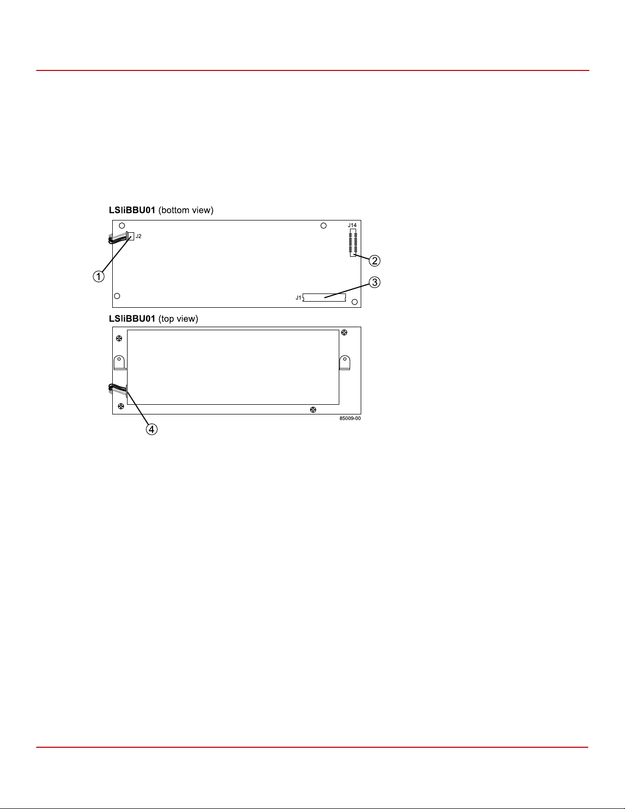
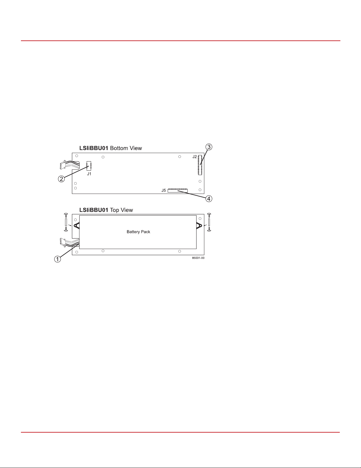
The following figure shows the top view and the bottom view of the LSIiBBU01 unit. (The top view is the side that you
can see after you install the unit on the motherboard or server chassis.) Note the J2 connector and the holes for the
screws that attach the LSIiBBU01 unit to the chassis.
Figure 1 LSIiBBU01 Intelligent Battery Backup Unit
Chapter 2: Installing the Cache Backup Products
Installing the LSIiBBU01 Unit
1. J2 Battery Pack Harness Connector
2. J14 Board-to-Board Connector
3. J1 20-pin In-line Connector
4. Battery Pack Harness
The LSIiBBU01 does not mount directly to the MegaRAID controller. Instead, use the supplied 10-in. cable to connect
the LSIiBBU01 unit to a RAID controller, as shown in the example in the following figure. The battery backup unit must
be mounted inside the chassis within 12 in. of the RAID controller.
NOTE Because server and workstation chassis vary from vendor to vendor,
there is no standard mounting option that is compatible with the
various system configurations. Therefore, the LSIiBBU01 battery kit
contains only the battery and the cable, allowing value-added
resellers (VARs) and chassis manufacturers to customize the location
of the remote battery to provide the most flexibility within
various environments.
Avago Technologies
- 12 -
Page 13

Cache Backup Products for MegaRAID SAS+SATA RAID Controllers User Guide
May 2015
Follow these steps to connect the LSIiBBU01 unit remotely to the MegaRAID SAS 8888ELP RAID controller.
1. Ground yourself, and remove the LSIiBBU01 unit from the package.
2. Use the three Phillips-head screws that are provided to secure the LSIiBBU01 unit to the motherboard or
server chassis.
3. Insert the battery pack harness connector at the end of the 5-pin cable into the J2 connector on the back side of
the unit.
4. Connect the 12-in. cable from the J1 connector on the LSIiBBU01 unit to the J10 battery backup connector on the
back of the RAID controller, as shown in the following figure.
Figure 2 Installing the LSIiBBU01 Unit on the MegaRAID SAS 8888ELP RAID Controller
Chapter 2: Installing the Cache Backup Products
Installing the LSIiBBU01 Unit
Avago Technologies
- 13 -
Page 14
Cache Backup Products for MegaRAID SAS+SATA RAID Controllers User Guide
May 2015
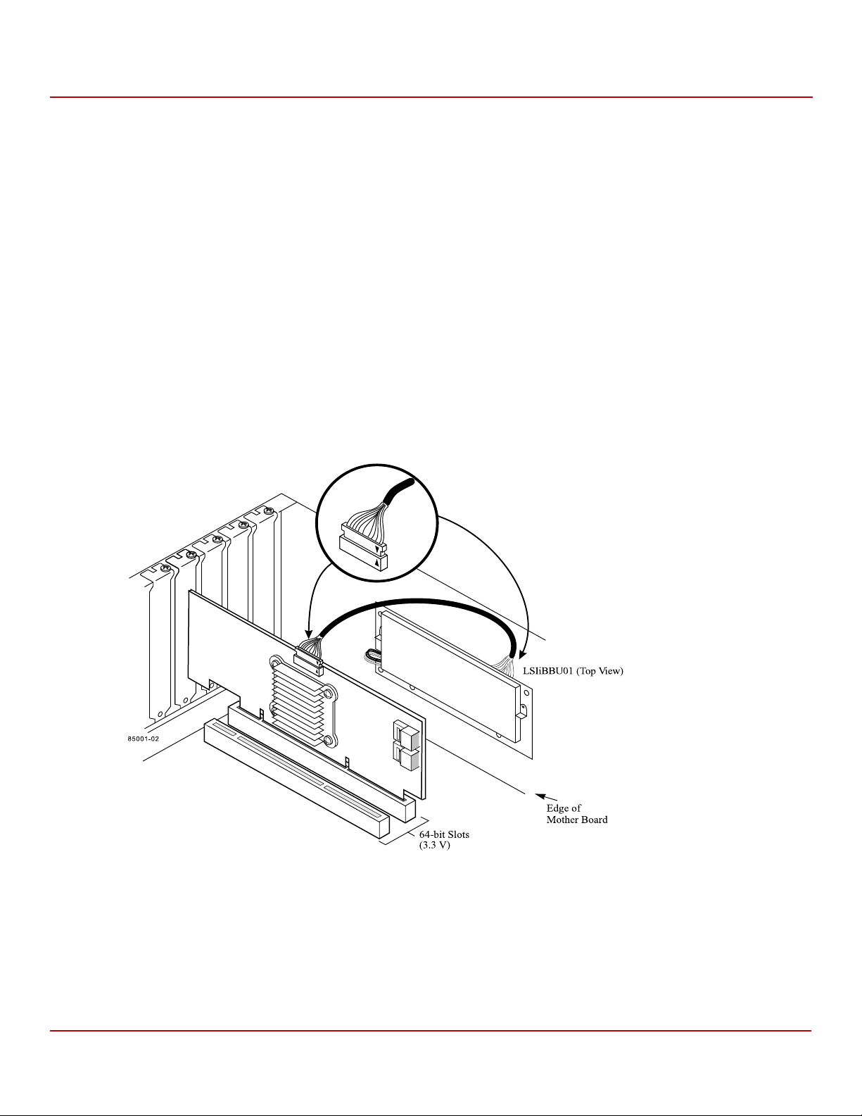
2.1.2 Installing the LSIiBBU01 (LiON) Unit
The Lithium ion (LiON) version of the LSIiBBU01 unit does not connect directly to the MegaRAID controllers. Instead, it
uses the supplied 20-pin, 10-in. cable to connect to them.
The LiON version of the LSIiBBU01 unit is used with these controllers:
MegaRAID SAS 8308ELP
MegaRAID SAS 8344ELP
MegaRAID SAS 84016E
The following figure shows the top view and the bottom view of the LiON LSIiBBU01 unit.
Figure 3 LSIiBBU01 Intelligent Battery Backup Unit
Chapter 2: Installing the Cache Backup Products
Installing the LSIiBBU01 Unit
1. Battery Pack Harness
2. J1 Battery Pack Harness Connector
3. J2 Board-to-Board Connector
4. J5 20-pin Inline Cable Connector
Avago Technologies
- 14 -
Page 15
Cache Backup Products for MegaRAID SAS+SATA RAID Controllers User Guide
May 2015
Follow these steps to install the LSIiBBU01 unit remotely to the MegaRAID SAS 8344ELP RAID controller.
1. Ground yourself, and remove the LSIiBBU01 unit from its package.
2. Use the three Phillips-head screws that are provided to secure the LSIiBBU01 to the motherboard or the
server chassis.
3. Insert the battery pack harness connector at the end of the battery pack harness into the J1 connector on the
bottom side of the LSIiBBU01 unit.
4. Connect the cable from the J5 connector on the LSIiBBU01 unit to the J11 battery backup connector on the back
side of the RAID controller, as shown in the following figure.
The connectors contain black triangles to help you install them correctly. Insert the cable connectors into the
controller connector and the iBBU connector so that the black triangles are aligned, as shown in the example in
the following figure.
CAUTION The cable connector is polarized and can be inserted into the J11
board battery connector only if the rails on the harness connector
align with the slots on the J11 connector. Do not force the cable into
the 20-pin in-line connector. The cable end should insert into the
connector with minimal resistance.
Figure 4 Installing the LSIiBBU01 on the MegaRAID SAS 8344ELP RAID Controller
Chapter 2: Installing the Cache Backup Products
Installing the LSIiBBU01 Unit
Avago Technologies
- 15 -
Page 16

Cache Backup Products for MegaRAID SAS+SATA RAID Controllers User Guide
May 2015
2.2 Installing the LSIiBBU05 Unit
The two types of LSIiBB05 units are:
LSI intelligent Battery Backup Unit 05– NiMH (Nickel Metal Hydride)
LSI intelligent Battery Backup Unit 05 – LiON (Lithium Ion)
WAR NIN G The battery used in this device might present a fire or chemical burn
hazard if mistreated. Do not disassemble, heat above 100 °C, or
incinerate. Dispose of used battery correctly. Keep away from children.
2.2.1 Installing the LSIiBB05 (NiMH) Unit
The LSIiBB05 NiMH intelligent BBU unit has built-in functionality to charge the battery pack automatically and to
communicate battery status information such as voltage, temperature, and current, to the host computer system.
The LSIiBB05 unit, which features NiMH battery cell technology, can be used in two application modes:
Mode 1: The LSIiBB05 unit mounts directly to the following SAS RAID controllers using a small board-to-board
connector (daughtercard):
— MegaRAID SAS 8704ELP
— MegaRAID SAS 8708ELP
Mode 2: The LSIiBB05 unit connects remotely to the following SAS RAID controller using a 12-in. cable:
— MegaRAID SAS 8888ELP
Chapter 2: Installing the Cache Backup Products
Installing the LSIiBBU05 Unit
Avago Technologies
- 16 -
Page 17
Cache Backup Products for MegaRAID SAS+SATA RAID Controllers User Guide
85006-00
iBBU Bottom View
J14
J1
J2
iBBU Top View
1
2
3
4
May 2015
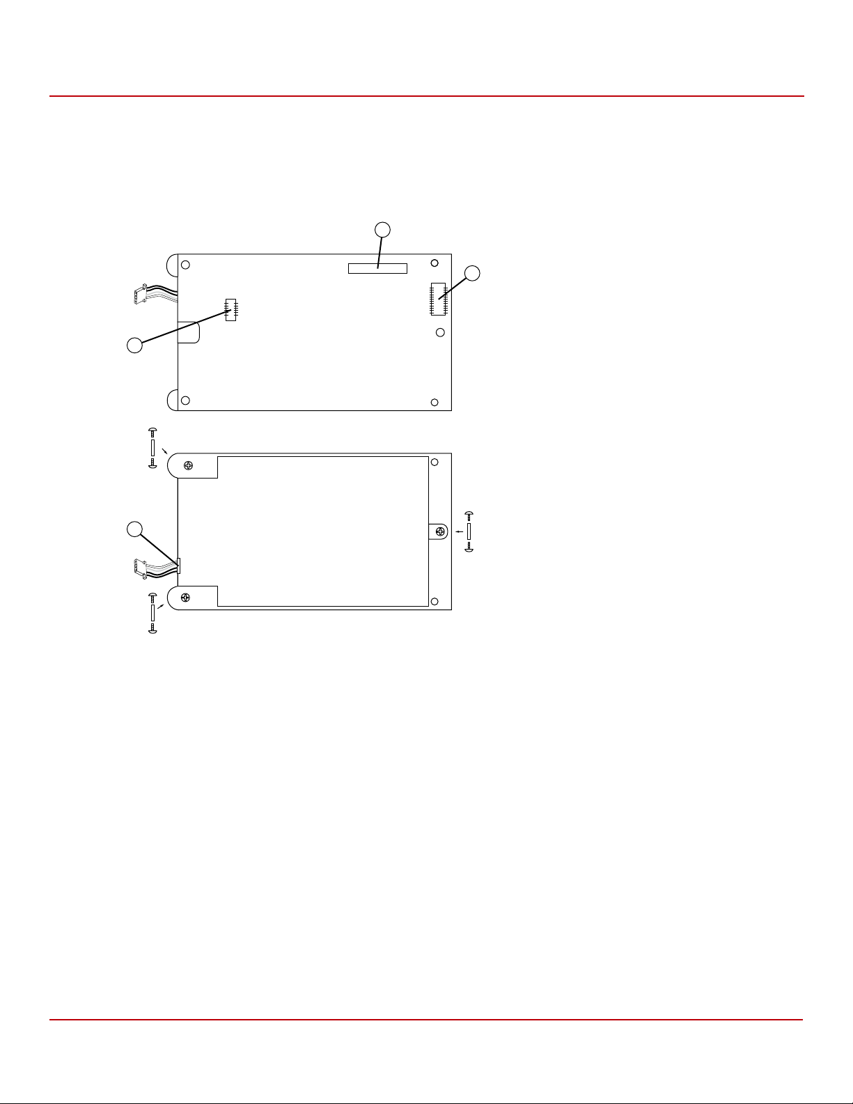
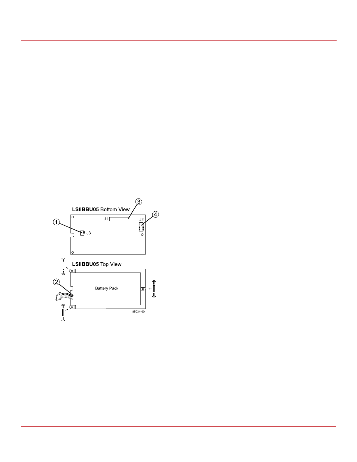
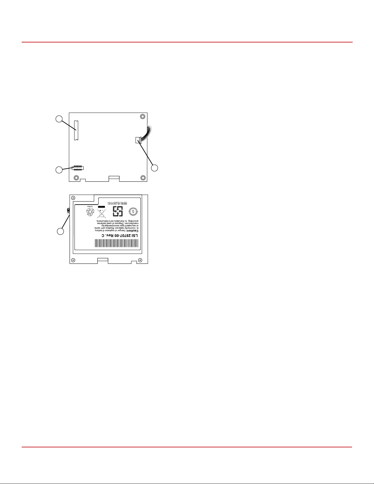
2.2.1.1 Top View and Bottom View of the LSIiBB05 NiMH Unit
The following figure displays the top view and the bottom view of the card, the screws, and the standoffs. (The top
view is the side that you can see after you install the LSIiBB05 unit on the RAID controller.) Note that this unit combines
a battery pack with a daughtercard.
Figure 5 LSIiBB05 NiMH Unit and Components
Chapter 2: Installing the Cache Backup Products
Installing the LSIiBBU05 Unit
1. J2 Battery Pack Harness Connector
2. J1 Connector
2.2.1.2 Connecting the LSIiBB05 NiMH Unit Directly to the RAID Controller
3. J14 Board-to-Board Connector
4. Battery Pack Harness
The first method for connecting the LSIiBB05 unit is to mount it directly to the RAID controller using a small
board-to-board connector known as a daughtercard. Follow the steps in this section to install the LSIiBB05 unit on the
MegaRAID SAS 8704ELP RAID controller or the MegaRAID SAS 8708ELP RAID controller.
Perform the following tasks described in this section to connect the LSIiBB05 NiMH unit directly to the RAID controller:
1. Remove the RAID controller from the host system. See Section 2.2.1.3, Removing the RAID Controller from the
Host Computer, on page 18.
2. Install the LSIiBBU05 NiMH unit directly to the RAID controller. See Section 2.2.1.4, Installing the LSIiBB05 NiMH
Unit on the RAID Controller, on page 18.
3. Reinstall the RAID controller on the motherboard on the host system. See Section 2.2.1.5, Reinstalling the RAID
Controller on the Motherboard, on page 19.
Avago Technologies
- 17 -
Page 18
Cache Backup Products for MegaRAID SAS+SATA RAID Controllers User Guide
May 2015
2.2.1.3 Removing the RAID Controller from the Host Computer
If the RAID controller is already installed in a host computer, follow these steps to remove it before you install the
LSIiBB05 unit:
1. Shut down the computer, turn off the power, and unplug the power cords.
2. Remove the cover from the computer according to the instructions in the system user’s manual so you can access
the RAID controller.
3. Ground yourself before touching the RAID controller.
4. Unplug all cables from the RAID controller, remove the screw that attaches the bracket to the computer case, and
carefully remove the RAID controller from the slot.
5. Place the RAID controller on a flat, clean, static-free surface, and continue with the next section.
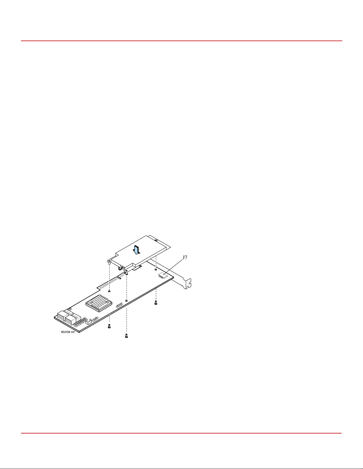
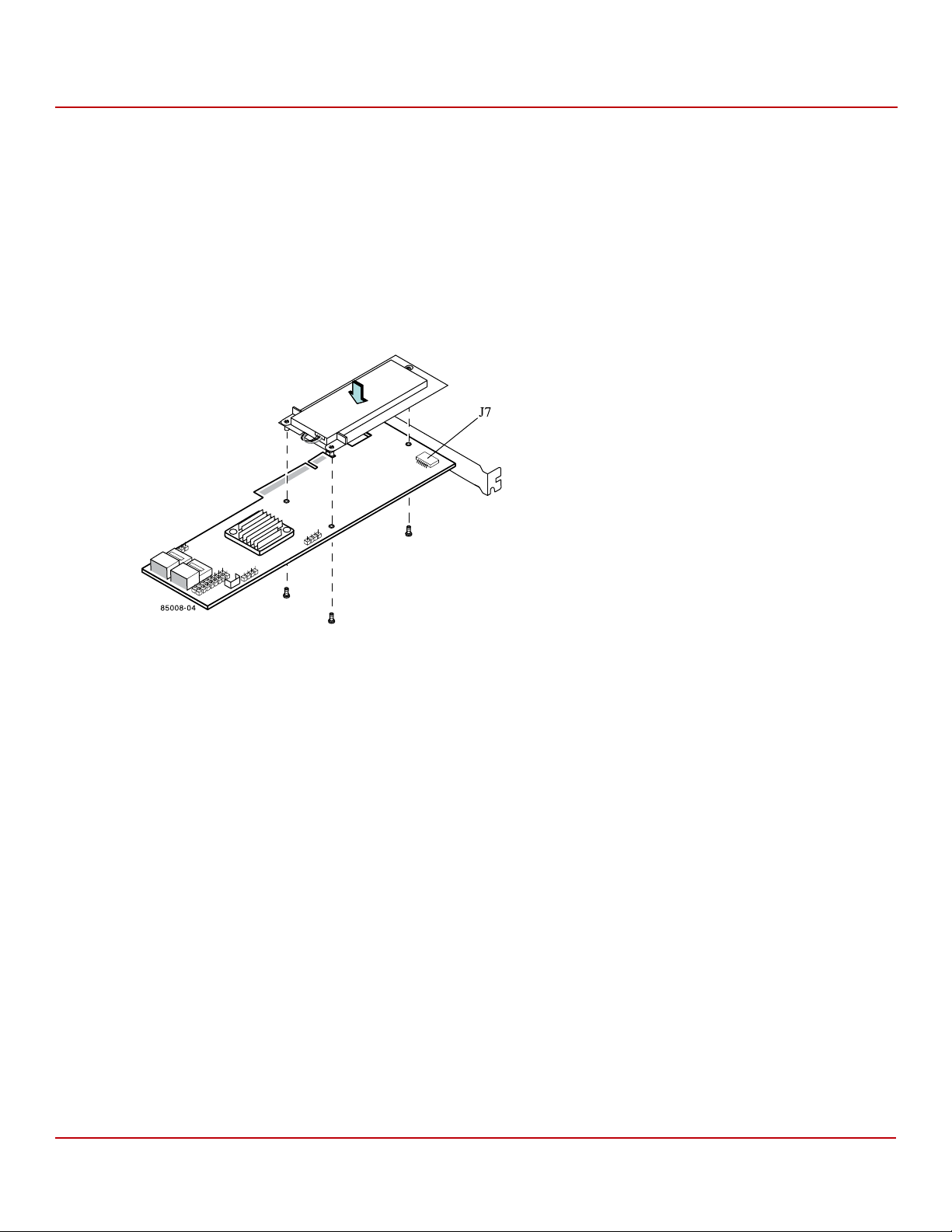
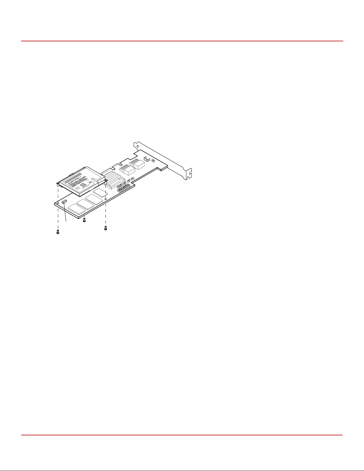
2.2.1.4 Installing the LSIiBB05 NiMH Unit on the RAID Controller
Perform the following steps to mount the LSIiBB05 unit directly to the RAID controller using the daughtercard. (All
components are installed on the bottom of the card. The battery is installed on the top. The maximum height of
components installed on the LSIiBBU05 is 0.125 in.
1. Ground yourself, and remove the LSIiBB05 daughtercard from the package.
2. Insert the battery pack harness connector at the end of the 5-pin cable into the 5-pin J2 connector on the back
side of the LSIiBB05 unit.
3. With the RAID controller on a flat, clean, static-free surface, hold the LSIiBB05 daughtercard so that the battery
side is facing upward, and the J14 board-to-board connector lines up with the J7 BBU connector on the RAID
controller, as shown in the following figure.
Chapter 2: Installing the Cache Backup Products
Installing the LSIiBBU05 Unit
Figure 6 Installing the LSIiBB05 Daughtercard on the MegaRAID SAS 8708ELP RAID Controller
4. Carefully press the LSIiBB05 unit onto the RAID controller, so that the two connectors are firmly joined.
5. Use the Phillips-head screws that are provided to secure the unit to the controller with the M2.50-0.45 x 5-mm
screws, and the 6-mm standoffs in the three screwholes.
The standoffs are threaded at both ends and a 6-mm screw goes into each end.
NOTE Center the screwdriver carefully to avoid stripping the screwhead.
Do not overtighten the screws.
Avago Technologies
- 18 -
Page 19
Cache Backup Products for MegaRAID SAS+SATA RAID Controllers User Guide
85008-05
Edge of Motherboard
LSIiBBU05 (Top View)
Bracket Scre w
Edge of
Motherboard
Press Here
Press Here
May 2015
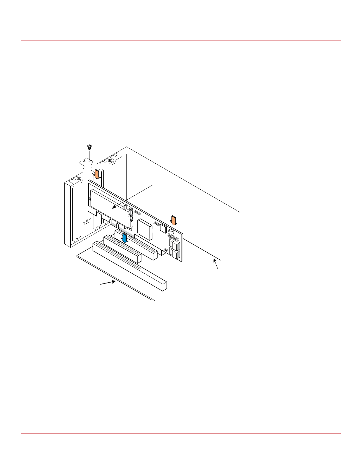
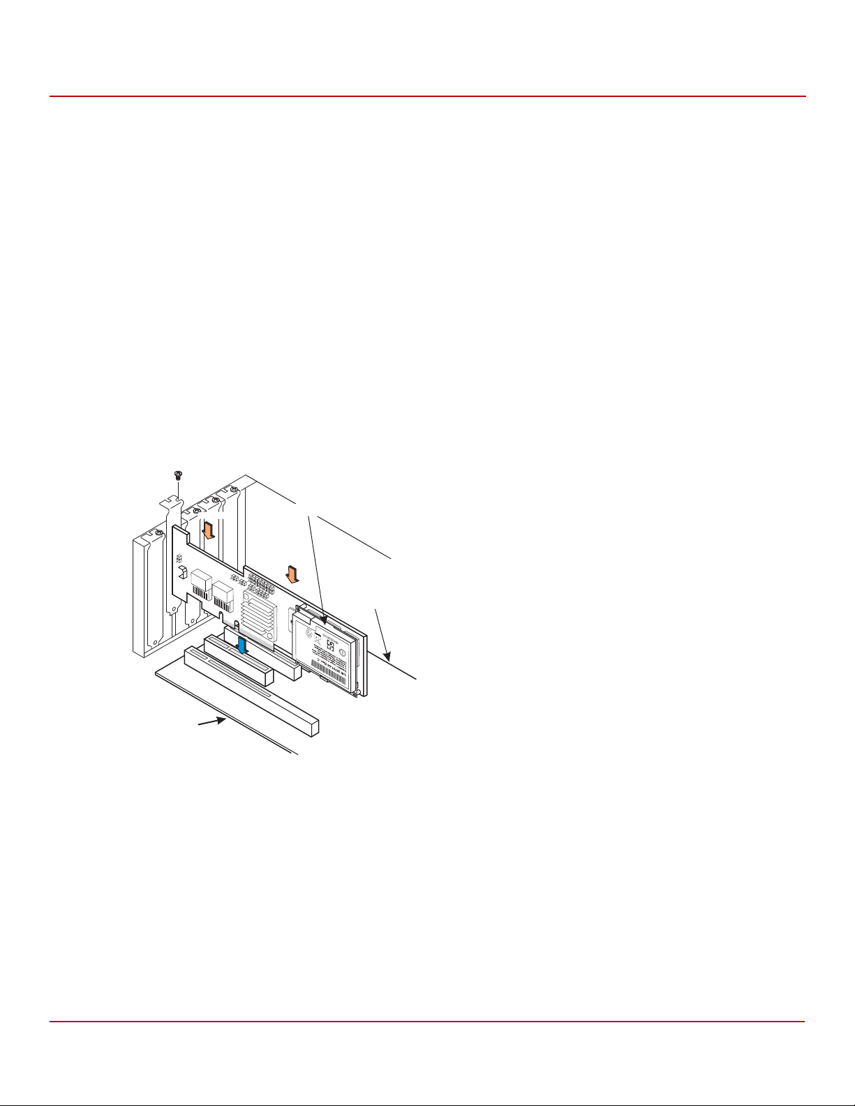
2.2.1.5 Reinstalling the RAID Controller on the Motherboard
Follow these steps to reinstall the controller in the computer.
1. Install the controller in the computer in the PCI Express® slot, as shown in the following figure.
2. Press down gently, but firmly, to seat the card correctly in the slot.
The bottom edge of the controller must be flush with the slot. Secure the controller to the computer chassis with
the bracket screw.
CAUTION Never apply pressure to the LSIiBB05 unit when you insert the RAID
controller. Instead, press down only on the top edge of the RAID
controller, as shown in the following figure.
Figure 7 Installing the MegaRAID SAS 8708ELP RAID Controller
Chapter 2: Installing the Cache Backup Products
Installing the LSIiBBU05 Unit
3. Attach the RAID controller to the computer chassis with the bracket screw.
4. Attach the cables, as needed, to the connectors on the RAID controller.
5. Replace the computer cover and reattach the power cords.
6. Turn on the power to the computer.
NOTE Refer to the MegaRAID SAS Software User Guide for information on
running the RAID configuration utility and the MegaRAID SAS Device
Driver Installation User Guide for information on installing the
software drivers.
Avago Technologies
- 19 -
Page 20
Cache Backup Products for MegaRAID SAS+SATA RAID Controllers User Guide
May 2015
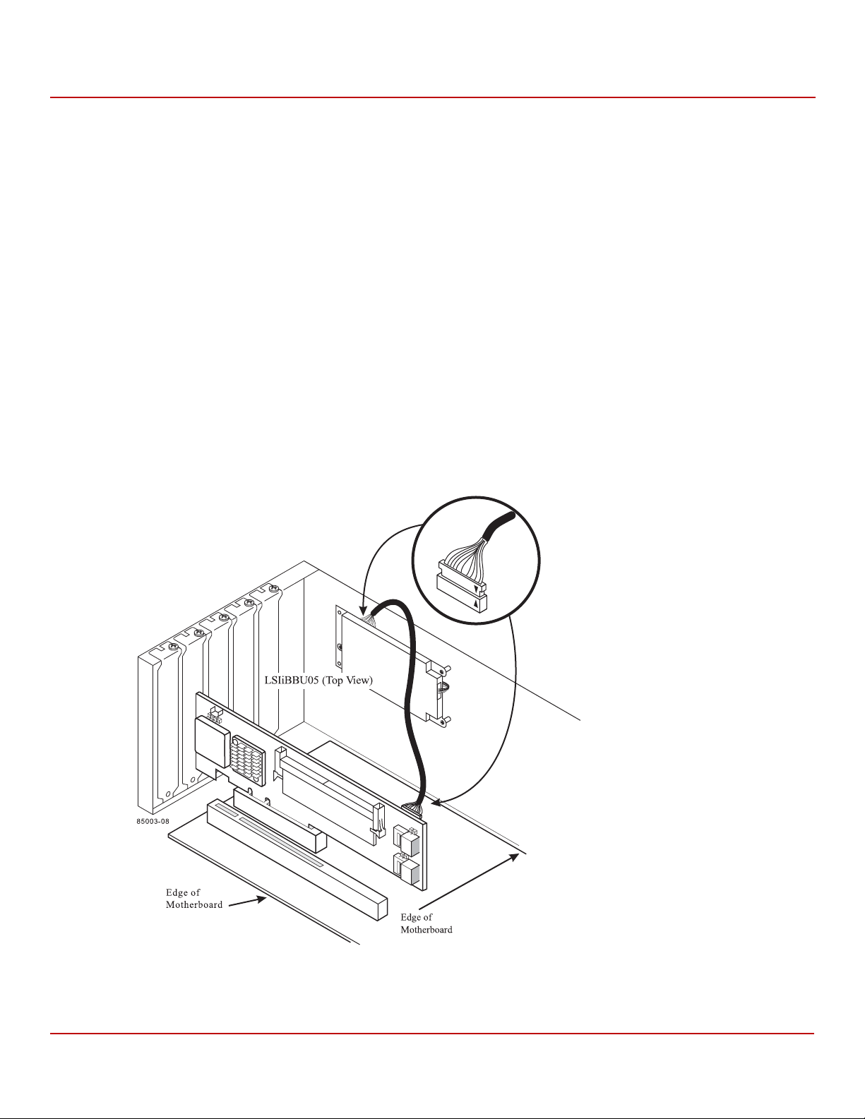
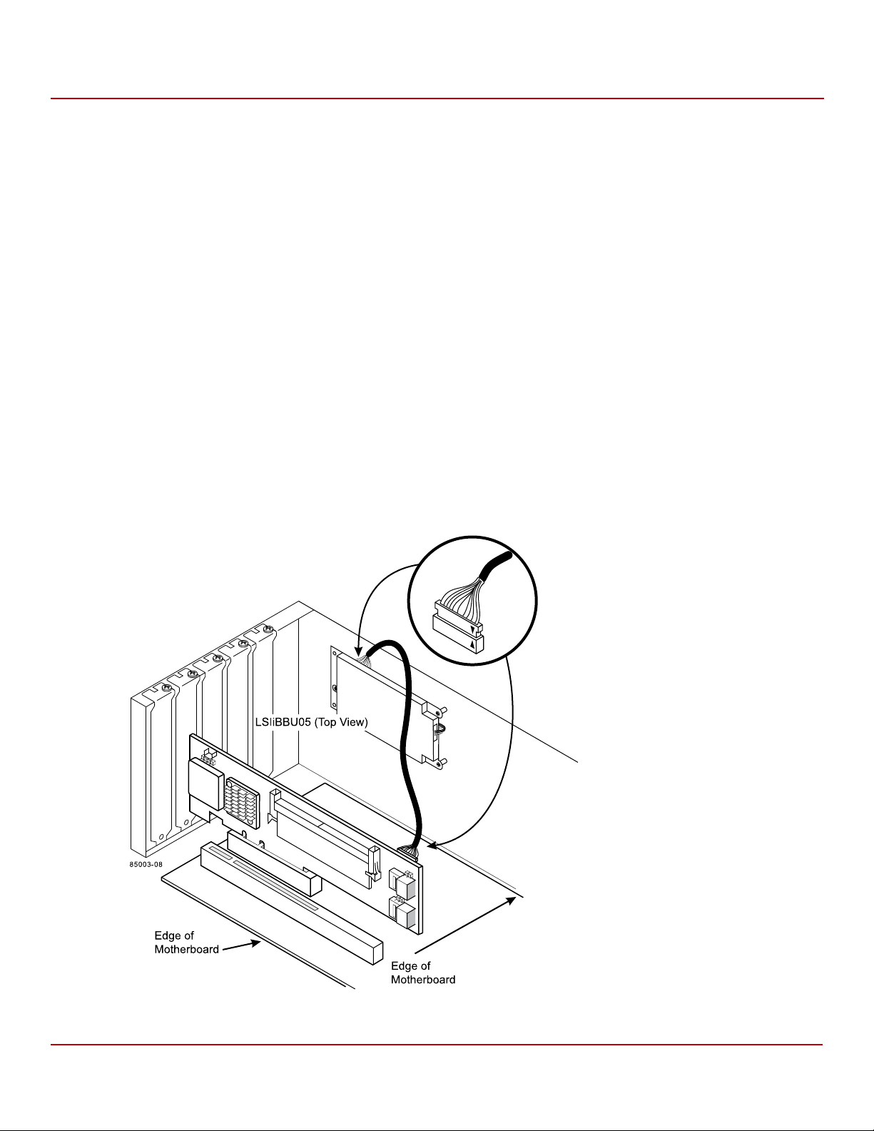
2.2.1.6 Connecting the LSIiBB05 NiMH Unit Remotely to the RAID Controller
You can connect the LSIiBB05 NiMH unit remotely to the MegaRAID SAS 8888ELP RAID controller, using the supplied
12-in. cable. The battery backup unit must be mounted inside the chassis within 10 in. of the RAID controller.
Because server and workstation chassis vary from vendor to vendor, there is no standard mounting option that is
compatible with the various system configurations. Therefore, the LSIiBB05 battery kit contains only the battery and
the cable, allowing VAR’s and chassis manufacturers to customize the location of the remote battery to provide the
most flexibility within various environments.
Follow these steps to install the LSIiBB05 unit remotely.
1. Ground yourself, and remove the LSIiBB05 unit from the package.
2. Use the three Phillips-head screws that are provided to secure the unit to the motherboard or server chassis.
3. Insert the battery pack harness connector at the end of the 5-pin cable into the J2 connector on the back side of
the LSIiBB05 unit.
4. Use the supplied 20-pin, 10-in. cable to connect the J1 connector on the LSIiBB05 unit to the J10 battery backup
connector on the back side of the MegaRAID SAS 8888ELP RAID controller, as shown in the following figure.
The connectors contain black triangles to help you install them correctly. Insert the cable connectors into the
controller connector and the iBBU connector so that the black triangles are aligned, as shown in the example in
the following figure.
Chapter 2: Installing the Cache Backup Products
Installing the LSIiBBU05 Unit
Figure 8 Connecting the LSIiBB05 NiMH Unit to the MegaRAID SAS 8888ELP RAID Controller
Avago Technologies
- 20 -
Page 21
Cache Backup Products for MegaRAID SAS+SATA RAID Controllers User Guide
May 2015
2.2.2 Installing the LSIiBBU05 (LiON) Unit
The LSIiBB05 LiON intelligent BBU unit is designed for use on MegaRAID SAS RAID controllers. It protects the integrity
of the cached data on a MegaRAID controller for up to 72 hours in the event of a complete AC power failure or a brief
power outage.
The LSIiBB05 LiON battery cell technology, can be used in two application modes:
Mode 1: The LSIiBB05 unit mounts directly to the following MegaRAID SAS RAID controllers using a small
board-to-board connector (daughtercard):
— MegaRAID SAS 8704ELP
— MegaRAID SAS 8708ELP
Mode 2: The LSIiBB05 unit supports remote connection to the following SAS RAID controller using a 12-in. cable:
— MegaRAID SAS 8888ELP
2.2.2.1 Top View and Bottom View of the LSIiBB05 LiON Unit
The following figure shows the top view and the bottom view of the LSIiBB05 unit, the M2.50-0.45 x 5-mm screws, and
the 6-mm standoffs. (The top view is the side that you can see after you install the unit on the RAID controller.) The
LSIiBB05 unit combines a battery pack with a daughtercard.
Figure 9 LSIiBB05 LiON Unit and Components
Chapter 2: Installing the Cache Backup Products
Installing the LSIiBBU05 Unit
1. J3 Battery Pack Harness Connector
2. Battery Pack Harness
3. J1 Connector
4. J2 Board-to-Board Connector
Avago Technologies
- 21 -
Page 22

Cache Backup Products for MegaRAID SAS+SATA RAID Controllers User Guide
May 2015
2.2.2.2 Connecting the LSIiBB05 LiON Unit Directly to the RAID Controller
The first method for connecting the LSIiBB05 unit is to mount it directly to the RAID controller using a small
board-to-board connector known as a daughtercard. Follow the steps in this section to install the LSIiBB05 unit on the
MegaRAID SAS 8704ELP RAID controller or the MegaRAID SAS 8708ELP RAID controller.
Perform the following tasks described in this section, in order, to connect the LSIiBB05 LiON unit directly to the
RAID controller.
1. Remove the RAID controller from the host computer. See Section 2.2.2.3, Removing the RAID Controller from the
Host Computer, on page 22.
2. Install the LSIiBBU05 LiON unit directly on the RAID controller. See Section 2.2.2.4, Installing the LSIiBB05 LiON
Unit Directly on the RAID Controller, on page 23.
3. Reinstall the RAID controller on the motherboard on the host computer. See Section 2.2.2.5, Reinstalling the RAID
Controller on the Motherboard, on page 24.
2.2.2.3 Removing the RAID Controller from the Host Computer
If the RAID controller is already installed in a computer, follow these steps to remove it before you install the
LSIiBB05 unit.
1. Shut down the computer, turn off the power, and unplug the power cords.
2. Remove the cover from the computer according to the instructions in the system user’s manual so you can access
the RAID controller.
3. Ground yourself before touching the RAID controller.
4. Unplug all cables from the RAID controller, remove the screw that attaches the bracket to the computer case, and
carefully remove the RAID controller from the slot.
5. Place the RAID controller on a flat, clean, static-free surface, and continue with the next section.
Chapter 2: Installing the Cache Backup Products
Installing the LSIiBBU05 Unit
Avago Technologies
- 22 -
Page 23
Cache Backup Products for MegaRAID SAS+SATA RAID Controllers User Guide
May 2015
2.2.2.4 Installing the LSIiBB05 LiON Unit Directly on the RAID Controller
Perform the following steps to mount the LSIiBB05 unit directly to the RAID controller using the daughtercard. (All
components are installed on the bottom of the card. The battery is installed on the top. The maximum height of
components installed on the LSIiBBU05 is 0.125”.)
1. Insert the battery pack harness connector at the end of the 5-pin cable into the 5-pin J3 connector on the back
side of the LSIiBB05 unit.
2. With the RAID controller on a flat, clean, static-free surface, hold the LSIiBB05 unit daughtercard so that the
battery side is facing upward, and the J2 board-to-board connector lines up with the J7 BBU connector on the
RAID controller, as shown in the following figure.
Figure 10 Installing the LiON LSIiBBU05 on the MegaRAID SAS 8708ELP RAID Controller
Chapter 2: Installing the Cache Backup Products
Installing the LSIiBBU05 Unit
3. Carefully press the LSIiBB05 unit onto the controller, so that the two connectors are firmly joined.
4. Use the Phillips-head screws that are provided to secure the LSIiBB05 unit to the controller with the M2.50-0.45 ×
5-mm screws, and the 6-mm standoffs in the three screwholes.
The standoffs are threaded at both ends and a 6mm screw goes into each end.
NOTE Center the screwdriver carefully to avoid stripping the screwhead.
Do not overtighten the screws.
Avago Technologies
- 23 -
Page 24

Cache Backup Products for MegaRAID SAS+SATA RAID Controllers User Guide
85008-05
Edge of Motherboard
LSIiBBU05 (Top View)
Bracket Scre w
Edge of
Motherboard
Press Here
Press Here
May 2015
2.2.2.5 Reinstalling the RAID Controller on the Motherboard
Follow these steps to reinstall the RAID controller on the motherboard.
1. Install the controller in the computer in the PCI Express slot, as shown in the following figure.
2. Press down gently, but firmly, to seat the card correctly in the slot.
The bottom edge of the controller must be flush with the slot.
3. Secure the controller to the computer chassis with the bracket screw.
CAUTION Never apply pressure to the LSIiBB05 unit when you insert the RAID
controller. Instead, press down only on the top edge of the RAID
controller, as shown in the following figure.
Figure 11 Reinstalling the MegaRAID SAS 8708ELP RAID Controller
Chapter 2: Installing the Cache Backup Products
Installing the LSIiBBU05 Unit
4. Attach the controller to the computer chassis with the bracket screw.
5. Attach the cables, as needed, to the connectors on the controller.
6. Replace the computer cover and reattach the power cords.
7. Turn on the power to the computer.
Avago Technologies
- 24 -
Page 25
Cache Backup Products for MegaRAID SAS+SATA RAID Controllers User Guide
May 2015
2.2.2.6 Connecting the LSIiBB05 LiON Unit Remotely to the RAID Controller
You can use the supplied 12-in. cable to connect the LSIiBB05 unit remotely to the MegaRAID SAS 8888ELP RAID
controller. The battery backup unit must be mounted inside the chassis within 10 in. of the RAID controller.
NOTE Because server and workstation chassis vary from vendor to vendor,
there is no standard mounting option that is compatible with the
various system configurations. Therefore, the LSIiBBU05 battery kit
contains only the battery and the cable, allowing VAR’s and chassis
manufacturers to customize the location of the remote battery to
provide the most flexibility within various environments.
Follow these steps to install the LSIiBB05 unit remotely.
1. Ground yourself, and remove the LSIiBB05 unit from the package.
2. Use the three Phillips-head screws that are provided to secure the unit to the motherboard or server chassis.
3. Insert the battery pack harness connector at the end of the 5-pin cable into the J3 connector on the back side of
the LSIiBB05 unit.
4. Connect the J1 connector on the LSIiBB05 unit to the J10 battery backup connector on the back side of the
MegaRAID SAS 8888ELP RAID controller, as shown in the following figure.
The connectors contain black triangles to help you install them correctly. Insert the cable connectors into the
controller connector and the iBBU connector so that the black triangles are aligned, as shown in the
following figure.
Chapter 2: Installing the Cache Backup Products
Installing the LSIiBBU05 Unit
Figure 12 Connecting the LSIiBBU05 Unit to the MegaRAID SAS 8888ELP RAID Controller
Avago Technologies
- 25 -
Page 26

Cache Backup Products for MegaRAID SAS+SATA RAID Controllers User Guide
May 2015
2.3 Installing the LSIiBBU06 Unit
The LSIiBBU06 LiON battery cell technology can be used in three application modes:
Mode 1: The LSIiBBU06 unit mounts directly to the following MegaRAID SAS RAID controllers using a small
board-to-board connector (daughter card):
— MegaRAID SAS 8704EM2
— MegaRAID SAS 8708EM2
Mode 2: The LSIiBBU08 unit is mounted on the system chassis and connected by 12-in. cable to a small
board-to-board cable adapter daughter card on the following MegaRAID SAS RAID controllers:
— MegaRAID SAS 8704EM2
— MegaRAID SAS 8708EM2
Mode 3: The LSIiBBU08 unit is mounted on a remote mount board and connected by 12-in. cable to a small
board-to-board cable adapter daughter card on the following MegaRAID SAS RAID controllers:
— MegaRAID SAS 8704EM2
— MegaRAID SAS 8708EM2
WAR NIN G The battery used in this device might present a fire or chemical burn
hazard if mistreated. Do not disassemble, heat above 100 °C, or
incinerate. Dispose of used battery correctly. Keep away from children.
Chapter 2: Installing the Cache Backup Products
Installing the LSIiBBU06 Unit
Avago Technologies
- 26 -
Page 27
Cache Backup Products for MegaRAID SAS+SATA RAID Controllers User Guide
85024-00
LSIiBBU06 (bottom view)
LSIiBBU06 (top view)
J4
J5
J2
4
1
2
3
May 2015
2.3.1 Top View and Bottom View of the LSIiBBU06 Unit
The following figure displays the top view and the bottom view of the LSIiBBU06 unit. (The top view is the side that
you can see after you install the LSIiBBU06 unit on the RAID controller.) Note that this unit combines a battery pack
with a daughtercard.
Figure 13 LSIiBBU06 Unit and Components
Chapter 2: Installing the Cache Backup Products
Installing the LSIiBBU06 Unit
1. J4 Battery Pack Harness Connector
2. J5 Board-to-Board Connector
3. J2 Connector
4. Battery Pack Harness Connector
Avago Technologies
- 27 -
Page 28

Cache Backup Products for MegaRAID SAS+SATA RAID Controllers User Guide
May 2015
2.3.2 Connecting a LSIiBBU06 Unit Directly to a RAID Controller
This section describes how to install the LSIiBBU06 unit directly on the MegaRAID SAS 8708EM2 RAID controller; you
can connect the LSIiBBU06 unit to the MegaRAID SAS 8704EM2 RAID controller in the same way.
Perform the following tasks to install the LSIiBBU06 unit directly:
1. Remove the RAID controller from the computer. For this procedure, see Section 2.3.2.1, Removing the RAID
Controller from the Computer, on page 28.
2. Install the LSIiBBU06 Unit on the RAID controller. For this procedure, see Section 2.3.2.2, Installing the LSIiBBU06
Unit Directly on the RAID Controller, on page 29.
3. Reinstall the RAID controller. For this procedure, see Section 2.3.2.3, Reinstalling the RAID Controller on the
Motherboard, on page 30.
CAUTION Electrostatic discharge (ESD) can damage the LSIiBBU06 unit and the
MegaRAID SASRAID controller. Make sure that you install the
LSIiBBU06 unit at an ESD-safe workstation that meets the
requirements of the Electronic Industries Alliance (EIA) EIA-625
(Requirements for Handling Electrostatic Discharge Sensitive Devices).
When you install the LSIiBBU06 unit, follow the ESD-recommended
practices in the latest revision of the IPC-A-610 (Acceptability of
Electronic Assemblies) standard.
Chapter 2: Installing the Cache Backup Products
Installing the LSIiBBU06 Unit
WAR NIN G Ground yourself, and disconnect the power cords from the system
before you remove the cover. Also, make sure that the system
is grounded.
2.3.2.1 Removing the RAID Controller from the Computer
If the RAID controller is already installed in a computer, follow these steps to remove the RAID controller before you
install the LSIiBBU06 unit:
1. Turn off the power to the computer, and unplug the power cords.
2. Remove the cover from the computer according to the instructions in the system user manual, to allow access to
the RAID controller.
3. Ground yourself before you touch the RAID controller.
4. Unplug all cables from the RAID controller, remove the screw that attaches the bracket to the computer case, and
carefully remove the controller from the PCIe® slot.
5. Place the RAID controller on a flat, clean, static-free surface, and continue with the next procedure.
Avago Technologies
- 28 -
Page 29
Cache Backup Products for MegaRAID SAS+SATA RAID Controllers User Guide
85024-01
J10
May 2015
2.3.2.2 Installing the LSIiBBU06 Unit Directly on the RAID Controller
Follow these steps to install the LSIiBBU06 unit on the RAID controller.
1. Ground yourself, and remove the LSIiBBU06 daughter card from the package.
2. Insert the battery pack harness connector at the end of the 5-pin cable into the 5-pin J4 connector on the back
side of the LSIiBBU06 unit.
3. Place the LSIiBBU08 unit top-side up on a flat, clean, static-free surface.
4. Place the RAID controller front-side up on a flat, clean, static-free surface.
5. Hold the LSIiBBU06 daughtercard so that the battery side is facing upward and the J5 connector lines up with the
J10 BBU connector on the RAID controller, as shown in the following figure.
Figure 14 Installing the LSIiBBU06 Daughtercard on the MegaRAID SAS 8708EM2 RAID Controller
Chapter 2: Installing the Cache Backup Products
Installing the LSIiBBU06 Unit
6. Carefully press the LSIiBBU06 unit onto the RAID controller so that the two connectors are firmly joined.
7. Use the Phillips-head screws and standoffs that are provided to secure the LSIiBBU06 daughter card to the RAID
controller using the three screw holes
The standoffs are threaded at both ends, and a screw goes into each end.
NOTE Center the screwdriver carefully to avoid stripping the screw heads.
Do not overtighten the screws.
Avago Technologies
- 29 -
Page 30
Cache Backup Products for MegaRAID SAS+SATA RAID Controllers User Guide
85024-02
Edge of Motherboard
Edge of
Motherboard
Bracket Screw
Press Here
Press Here
LSIiBBU06 (Top View)
May 2015
2.3.2.3 Reinstalling the RAID Controller on the Motherboard
Follow these steps to reinstall the RAID controller on the motherboard.
1. With the power to the chassis still turned off, and the power cords unplugged, make sure that the chassis is
grounded and has no AC power.
2. Install the RAID controller into a PCIe slot on the motherboard, as shown in the following figure.
3. Press down gently, but firmly, to seat the card correctly in the slot.
The bottom edge of the RAID controller must be flush with the slot.
CAUTION Never apply pressure to the LSIiBBU06 unit when you insert the RAID
controller. Instead, press down only on the top edge of the RAID
controller, as shown in the following figure.
NOTE This controller is a PCIe x8 card, and it can operate in x8 or x16 slots.
Some PCIe slots, however, support only PCIe graphics cards; if a
controller is installed in one of these slots, the controller will not
function. Refer to the guide for your motherboard for information
about the PCIe slot.
Figure 15 Reinstalling the MegaRAID SAS 8708EM2 RAID Controller
Chapter 2: Installing the Cache Backup Products
Installing the LSIiBBU06 Unit
4. Secure the RAID controller to the computer chassis with the bracket screw.
5. Attach the cables from the internal port connectors to the drives.
6. Reinstall the computer cover, and reattach the power cords.
7. Turn on the power to the computer.
Avago Technologies
- 30 -
Page 31

Cache Backup Products for MegaRAID SAS+SATA RAID Controllers User Guide
May 2015
2.3.3 Connecting the LSIiBBU06 Unit Remotely to the RAID Controller
You can connect the LSIiBBU06 unit remotely to the MegaRAID 8708EM2 SAS RAID controller using the supplied
20-pin cable.
Follow these steps to install the LSIiBBU06 unit remotely to the RAID controller.
1. Ground yourself, and remove the LSIiBBU06 unit from the package.
2. Use the three Phillips-head screws that are provided to secure the unit to the motherboard or the server chassis.
3. Insert the battery pack harness connector at the end of the 5-pin cable into the J4 connector on the back side of
the unit.
4. Use the supplied 20-pin, 10-in. cable to connect the J2 connector on the LSIiBBU06 unit to the J10 battery backup
connector of the RAID controller, as shown in the following figure.
The connectors contain black triangles to help you install them correctly. The triangles identify pin 1 on each
connector. Insert the cable connectors into the controller connector and the iBBU connector so that the triangles
are aligned, as shown in the following figure.
Figure 16 Connecting the LSIiBBU06 Unit to the MegaRAID SAS 8708EM2 RAID Controller
Chapter 2: Installing the Cache Backup Products
Installing the LSIiBBU06 Unit
Avago Technologies
- 31 -
Page 32

Cache Backup Products for MegaRAID SAS+SATA RAID Controllers User Guide
May 2015
Chapter 2: Installing the Cache Backup Products
Installing the LSIiBBU06 Unit
2.3.4 Connecting a Remote LSIiBBU06 Unit to a MegaRAID SAS RAID Controller
The following sections describe the two methods you can use to connect a LSIiBBU06 unit remotely to the MegaRAID
SAS 8708EM2 RAID controller using the supplied 12-in., 20-pin cable. You can connect the LSIiBBU06 unit to the
MegaRAID SAS 8704EM2 RAID controller using the same methods.
The remote installation methods are:
1. Connect the 12-in. cable (sold separately in a Remote Battery Kit) between a remote LSIiBBU06 unit and a
board-to-board cable adapter card on the RAID controller. Reinstall the RAID controller, and mount the LSIiBBU06
unit on the system chassis or motherboard. For these procedures, see Section 2.3.5, Connecting a Remote
LSIiBBU06 Unit on the System Chassis to a Board-to-Board Adapter Card on a RAID Controller, on page 32.
2. Connect the 12-in. cable between an LSIiBBU08 unit that is on a remote mount board and a board-to-board cable
adapter card on the RAID controller. Reinstall the RAID controller, and then install the remote mount board. For
these procedures, see Section 2.3.6, Connecting an LSIiBBU06 Unit from a Remote Mount Board to a
Board-to-Board Cable Adapter Card on a RAID Controller, on page 36.
2.3.5 Connecting a Remote LSIiBBU06 Unit on the System Chassis to a Board-to-Board Adapter Card on a RAID Controller
This section describes how to connect the remote LSIiBBU06 unit mounted on the system chassis to a board-to-board
cable adapter card on your MegaRAID SAS 8704EM2 RAID controller or MegaRAID SAS 8708EM2 RAID controller. The
remote LSIiBBU06 unit connects by cable to the adapter card.
WAR NIN G Ground yourself, and disconnect the power cords from the system
before you remove the cover. Also, make sure that the system
is grounded.
Perform the following tasks:
1. Remove the RAID controller from the computer. For this procedure, see Section 2.3.5.1, Removing the RAID
Controller from the Computer.
2. Install the board-to-board adapter card on the RAID controller. For this procedure, see Section 2.3.5.2, Installing
the Board-to-Board Adapter Card on the RAID Controller.
3. Connect the cable between the board-to-board adapter card on the RAID controller and the LSIiBBU06 Unit on
the System Chassis. For this procedure, see Section 2.3.5.3, Connecting the Cable between the Board-to-Board
Adapter Card on the RAID Controller and the LSIiBBU06 Unit on the System Chassis, on page 34.
4. Reinstall the RAID controller. For this procedure, see Section 2.3.5.4, Reinstalling the RAID Controller, on page 35.
NOTE Because server chassis design and workstation chassis design vary
from vendor to vendor, no standard mounting option is available that
is compatible with the various system configurations. Therefore, the
LSIiBBU08 battery kit contains only the battery, board-to-board cable
adapter daughter card, and the cable, allowing value-added reseller’s
(VAR’s) and chassis manufacturers to customize the location of
the remote iBBU unit to provide the most flexibility within
various environments.
2.3.5.1 Removing the RAID Controller from the Computer
Follow these steps to remove the RAID controller from the computer.
1. Turn off the power to the computer, and unplug the power cords.
Avago Technologies
- 32 -
Page 33

Cache Backup Products for MegaRAID SAS+SATA RAID Controllers User Guide
3_00719-00
J10
May 2015
2. Remove the cover from the computer, according to the instructions in the system user manual, to allow access to
the controller.
3. Ground yourself before you touch the controller.
4. Unplug all cables from the controller, remove the screw attaching the bracket to the computer chassis, and
carefully remove the controller from the slot.
5. Place the controller on a flat, clean, static-free surface, and continue with the next procedure.
2.3.5.2 Installing the Board-to-Board Adapter Card on the RAID Controller
Follow these steps to install the board-to-board adapter card on the controller, as shown in the following figure.
1. With the controller on a flat, clean, static-free surface, ground yourself, and remove the adapter card, standoff, and
screws from the package.
2. Place the standoff on the controller so that the bottom side is positioned over the screw hole next to the
J10 connector on the controller.
3. Use one of the screws to secure the standoff to the controller.
NOTE Center the screwdriver carefully to avoid stripping the screw head.
Do not overtighten the screws.
4. Hold the adapter card so that the J1 board-to-board connector lines up with the J10 board-to-board connector
on the RAID controller.
5. Carefully press the J1 connector on the adapter card into the J10 connector on the controller so that the two
connectors are joined firmly.
The connectors fit only when they are in the correct alignment.
6. Use the other screw to secure the adapter card to the controller, and continue with the next procedure.
Chapter 2: Installing the Cache Backup Products
Installing the LSIiBBU06 Unit
Figure 17 Connecting the Board-to-Board Adapter Card to the MegaRAID SAS 8708EM2 RAID Controller
Avago Technologies
- 33 -
Page 34

Cache Backup Products for MegaRAID SAS+SATA RAID Controllers User Guide
3_00776-00
May 2015
Chapter 2: Installing the Cache Backup Products
Installing the LSIiBBU06 Unit
2.3.5.3 Connecting the Cable between the Board-to-Board Adapter Card on the RAID Controller and the LSIiBBU06 Unit on the System Chassis
Follow these steps to connect the cable between the board-to-board adapter card on the RAID controller and the
LSIiBBU06 unit.
1. Ground yourself, and remove the LSIiBBU06 unit from the package.
2. Use the three Phillips-head screws that are provided to secure the LSIiBBU06 unit to the motherboard or the
server chassis.
3. Insert the battery pack harness connector at the end of the colored wires into the J4 connector on the rear side of
the LSIiBBU06 unit.
4. Insert the 20-pin cable connector at one end of the 12-in. cable into the 20-pin J2 cable connector on the
LSIiBBU06 unit and the 20-pin cable connector at the other end into the 20-pin JT1 battery backup connector on
the board-to-board cable adapter daughter card, as shown in the following figure.
CAUTION Damage to the battery backup unit will occur when power is applied
to the system if the cable assembly connectors are installed backwards
in either the JT1 board-to-board connector or the J2 battery
connector. The cable connectors are polarized, and the keying features
of the connector are designed to allow the connectors to be attached
in only one orientation. The cable end inserts into the connector with
only minimal resistance.
Even with the keying features, if excessive force is used, it is possible
to install these connectors incorrectly. To assist in correct alignment,
the small triangles that designate pin 1 on each connector have been
marked in black. Be sure these triangles line up as shown in the
illustrations. Also, the wire that connects to pin 1 of each end of the
cable assembly is yellow on most Avago cables.
Figure 18 Connecting the Remote LSIiBBU08 Unit to the Board-to-Board Cable Adapter Daughter Card on the MegaRAID
SAS 8708EM2 RAID Controller
Avago Technologies
- 34 -
Page 35

Cache Backup Products for MegaRAID SAS+SATA RAID Controllers User Guide
Edge of Motherboard
Screw
Press
Here
Press
Here
3_00777-00
May 2015
2.3.5.4 Reinstalling the RAID Controller
Follow these steps to install the controller in the computer.
1. With the power to the chassis still turned off, and the power cords unplugged, make sure that the chassis is
grounded and has no AC power.
2. Insert the RAID controller in a PCI Express slot on the motherboard, as shown in the following figure.
NOTE This controller is a PCIe x8 card, and it can operate in x8 or x16 slots.
Some PCIe slots, however, support only PCIe graphics cards; a
controller installed in one of these slots will not function. Refer to the
guide for your motherboard for information about the PCIe slot.
3. Press down gently, but firmly, to seat the card correctly in the slot.
Figure 19 Reinstalling the RAID Controller
Chapter 2: Installing the Cache Backup Products
Installing the LSIiBBU06 Unit
4. Secure the controller to the computer chassis with the bracket screw.
5. Attach the cables from the internal port connectors to the drives.
6. Replace the computer cover, and reattach the power cords.
7. Turn on the power to the computer.
NOTE Refer to the MegaRAID SAS Software User Guide for information on
running the RAID configuration utility and the MegaRAID SAS Device
Driver Installation User Guide for information on installing the drivers.
Avago Technologies
- 35 -
Page 36

Cache Backup Products for MegaRAID SAS+SATA RAID Controllers User Guide
May 2015
Chapter 2: Installing the Cache Backup Products
Installing the LSIiBBU06 Unit
2.3.6 Connecting an LSIiBBU06 Unit from a Remote Mount Board to a Board-to-Board Cable Adapter Card on a RAID Controller
This section describes how to connect an LSIiBBU06 unit on a remote mount board to a board-to-board cable adapter
card on your RAID controller. This procedure shows installation on the MegaRAID SAS 8708EM2 RAID controller; you
can connect the LSIiBBU08 unit to the MegaRAID SAS 8704EM2 RAID controller in the same way.
NOTE The remote mount board can hold up to two LSIiBBU06 units. The
procedure in this section shows the remote mount board with one
LSIiBBU06 unit.
Perform the following tasks.
1. Remove the RAID controller from the computer. For this procedure, see Section 2.3.6.1, Removing the RAID
Controller from the Computer.
2. Install the board-to-board adapter card on the RAID controller. For this procedure, see Section 2.3.6.2, Installing
the Board-to-Board Cable Adapter Card on the RAID Controller.
3. Connect the cable between the board-to-board adapter card on the RAID controller and the LSIiBBU06 Unit on
the System Chassis. For this procedure, see Section 2.3.6.3, Connecting the Cable Between the LSIiBBU06 Unit on
the Remote Mount Board and the Board-to-Board Cable Adapter Card on the RAID Controller, on page 38.
4. Reinstall the RAID controller. For this procedure, see Section 2.3.6.4, Reinstalling the RAID Controller, on page 39.
5. Install the remote mount board. For this procedure, see Section 2.3.6.5, Installing the Remote Mount Board, on
page 40.
WAR NIN G Ground yourself, and disconnect the power cords from the system
before you remove the cover. Also, make sure that the system
is grounded.
2.3.6.1 Removing the RAID Controller from the Computer
Follow these steps to remove the RAID controller from the computer.
1. Turn off the power, and unplug the power cords.
2. Ground yourself, and make sure that the system is grounded.
3. Remove the cover from the computer, according to the instructions in the system user’s manual, to allow access
to the controller.
4. Unplug all cables from the controller, remove the screw that attaches the bracket to the computer chassis, and
carefully remove the controller from the slot.
5. Place the controller on a flat, clean, static-free surface, and continue with the next procedure.
Avago Technologies
- 36 -
Page 37

Cache Backup Products for MegaRAID SAS+SATA RAID Controllers User Guide
3_00719-00
J10
May 2015
2.3.6.2 Installing the Board-to-Board Cable Adapter Card on the RAID Controller
Follow these steps to install the board-to-board adapter card on the controller.
1. With the controller on a flat, clean, static-free surface, ground yourself, and remove the adapter card, standoff, and
screws from the package.
2. Place the standoff on the controller so that the bottom side is positioned over the screw hole next to the J1
connector on the controller.
3. Use one of the screws to secure the standoff to the controller, as shown in the following figure.
NOTE Center the screwdriver carefully to avoid stripping the screw head.
Do not overtighten the screws.
4. Hold the adapter card so that the J2 board-to-board connector lines up with the J10 board-to-board connector
on the RAID controller.
5. Carefully press the J2 connector on the adapter card into the J10 connector on the controller so that the two
connectors are joined firmly.
6. The connectors fit only when they are in the correct alignment.
7. Use the other screw to secure the adapter card to the controller, and continue with the next procedure.
Figure 20 Connecting the Board-to-Board Adapter Card to the MegaRAID SAS 8708EM2 RAID Controller
Chapter 2: Installing the Cache Backup Products
Installing the LSIiBBU06 Unit
Avago Technologies
- 37 -
Page 38

Cache Backup Products for MegaRAID SAS+SATA RAID Controllers User Guide
3_00705-00
May 2015
Chapter 2: Installing the Cache Backup Products
Installing the LSIiBBU06 Unit
2.3.6.3 Connecting the Cable Between the LSIiBBU06 Unit on the Remote Mount Board and the Board-to-Board Cable Adapter Card on the RAID Controller
Follow these steps to connect the cable between the LSIiBBU06 unit on the remote mount board and the
board-to-board cable adapter card on your RAID controller.
1. With the controller on a flat, clean, static-free surface, ground yourself, and make sure that the system
is grounded.
2. Insert the 20-pin cable connector at one end of the 12-in. cable into the 20-pin J2 cable connector on the
LSIiBBU08 unit on the remote mount board and the 20-pin cable connector at the other end into the
20-pin JT1 board-to-board cable adapter daughter card on the RAID controller.
CAUTION Damage to the battery backup unit will occur when power is applied
to the system if the cable assembly connectors are installed backwards
in either the JT1 board-to-board connector or the J2 battery
connector. The cable connectors are polarized, and the keying features
of the connector are designed to allow the connectors to be attached
in only one orientation. The cable end inserts into the connector with
only minimal resistance.
Even with the keying features, if excessive force is used, it is possible
to install these connectors incorrectly. To assist in correct alignment,
the small triangles that designate pin 1 on each connector have been
marked in black. Be sure these triangles line up as shown in the
illustrations. Also, the wire that connects to pin 1 of each end of the
cable assembly is yellow on most Avago cables.
Figure 21 Connecting the LSIiBBU06 Unit on the Remote Mount Board to the Board-to-Board Cable Adapter Card on the
MegaRAID SAS 8708EM2 RAID Controller
Avago Technologies
- 38 -
Page 39

Cache Backup Products for MegaRAID SAS+SATA RAID Controllers User Guide
Edge of Motherboard
Screw
Press
Here
Press
Here
3_00706-00
May 2015
2.3.6.4 Reinstalling the RAID Controller
Follow these steps to reinstall the RAID controller in the computer.
1. With the power to the chassis still turned off and the power cords unplugged, make sure that the chassis is
grounded and has no AC power.
2. Insert the RAID controller into a PCI Express slot on the motherboard, as shown in the following figure.
NOTE This controller is a PCIe x8 card, and it can operate in x8 or x16 slots.
However, some PCIe slots support only PCIe graphics cards; a
controller installed in one of these slots will not function. Refer to the
guide for your motherboard for information about the PCIe slot.
3. Press down gently, but firmly, to seat the controller correctly in the slot.
Figure 22 Reinstalling the RAID Controller
Chapter 2: Installing the Cache Backup Products
Installing the LSIiBBU06 Unit
4. Secure the controller to the computer chassis with the bracket screw.
Avago Technologies
- 39 -
Page 40

Cache Backup Products for MegaRAID SAS+SATA RAID Controllers User Guide
Screw
Press
Here
Press
Here
3_00707-00
May 2015
2.3.6.5 Installing the Remote Mount Board
Follow these steps to install the remote mount board in the computer.
1. With the power to the chassis still turned off, and the power cords unplugged, make sure that the chassis is
grounded and has no AC power.
2. Insert the remote mount board in a PCI Express slot on the motherboard, as shown in the following figure.
NOTE This controller is a PCIe x8 card, and it can operate in x8 or x16 slots.
However, some PCIe slots support only PCIe graphics cards; a
controller installed in one of these slots will not function. Refer to the
guide for your motherboard for information about the PCIe slot.
3. Press down gently, but firmly, to seat the board correctly in the slot.
Figure 23 Installing the Remote Mount Board
Chapter 2: Installing the Cache Backup Products
Installing the LSIiBBU06 Unit
4. Secure the remote mount board to the computer chassis with the bracket screw.
5. Attach the cables from the internal port connectors to the drives.
6. Reinstall the computer cover, and reattach the power cords.
7. Turn on the power to the computer.
Refer to the MegaRAID SAS Software User Guide for information on running the RAID configuration utility and the
MegaRAID SAS Device Driver Installation User Guide for information on installing the software drivers.
Avago Technologies
- 40 -
Page 41

Cache Backup Products for MegaRAID SAS+SATA RAID Controllers User Guide
May 2015
2.4 Installing the LSIiBBU07 Unit
The LSIiBBU07 LiON battery cell technology, can be used in four application modes:
Mode 1: The LSIiBBU07 unit uses a small board-to-board connector (daughtercard) to mount directly to the
following MegaRAID SAS RAID controllers:
— MegaRAID SAS 8880EM2
— MegaRAID SAS 9260-4i
— MegaRAID SAS 9260-8i
— MegaRAID SAS 9260DE-8i
— MegaRAID SAS 9261-8i
— MegaRAID SAS 9280-4i4e
— MegaRAID SAS 9280-8e
— MegaRAID SAS 9280DE-8e
To mount the LSIiBBU07 unit directly, follow the steps in Section 2.4.2, Installing the LSIiBBU07 Unit Directly on a
RAID Controller, on page 43.
Mode 2: Connect a 12-in. cable (sold separately in a Remote Battery Kit) between a remote LSIiBBU07 unit and
the remote BBU connector on your RAID controller. Reinstall the RAID controller and mount the LSIiBBU07 unit on
the system chassis or motherboard. Use this mode with the following MegaRAID SAS RAID controllers:
— MegaRAID SAS 9260-16i
— MegaRAID SAS 9261-8i
— MegaRAID SAS 9280-4i4e
— MegaRAID SAS 9280-8e
— MegaRAID SAS 9280DE-8e
— MegaRAID SAS 9280-16i4e
— MegaRAID SAS 9280-24i4e
To connect a 12-in. cable between a remote LSIiBBU07 unit mounted on the system chassis and the BBU
connector on the RAID controllerLSIiBBU07, follow the steps in Section 2.4.4, Connecting the Remote LSIiBBU07
Unit to the BBU Connector on the RAID Controller, on page 46.
Mode 3: Connect a 12-in. cable between a remote LSIiBBU07 unit and a board-to-board cable adapter card on the
RAID controller. Reinstall the RAID controller, and mount the LSIiBBU07 unit on the system chassis or
motherboard. Use this mode with the following MegaRAID SAS RAID controllers:
— MegaRAID SAS 8880EM2
— MegaRAID SAS 9261-8i
— MegaRAID SAS 9280-4i4e
— MegaRAID SAS 9280-8e
— MegaRAID SAS 9280DE-8e
To connect a 12-in. cable between a remote LSIiBBU07 unit mounted on the system chassis and a board-to-board
cable adapter card that is installed on the RAID controller, follow the steps in Section 2.4.5, Connecting a Remote
LSIiBBU07 to a Daughter Card on the RAID Controller, on page 49.
Mode 4: Connect a 12-in. cable between a LSIiBBU08 unit on a remote mount board and a board-to-board cable
adapter card that is installed on the RAID controller. Reinstall the RAID controller, and then install the remote
mount board. Use this mode with the following MegaRAID SAS RAID controllers:
— MegaRAID SAS 8880EM2
— MegaRAID SAS 9260-4i
— MegaRAID SAS 9260-8i
— MegaRAID SAS 9261-8i
— MegaRAID SAS 9280-4i4e
Chapter 2: Installing the Cache Backup Products
Installing the LSIiBBU07 Unit
Avago Technologies
- 41 -
Page 42

Cache Backup Products for MegaRAID SAS+SATA RAID Controllers User Guide
May 2015
— MegaRAID SAS 9280-8e
To connect a 12-in. cable between a LSIiBBU08 unit on a remote mount board and a board-to-board cable
adapter card on the RAID controller, follow the steps in Section 2.4.6, Connecting an LSIiBBU07 Unit from a
Remote Mount Board to a Board-to-Board Adapter Card on a RAID Controller, on page 53.
WAR NIN G The battery used in this device might present a fire or chemical burn
hazard if mistreated. Do not disassemble, heat above 100 °C, or
incinerate. Dispose of used battery correctly. Keep away from children.
NOTE The procedures in this guide describe how to install the LSIiBBU07 unit
on the MegaRAID SAS 8880EM2 RAID controller. You can connect the
LSIiBBU07 unit in the same way to the other MegaRAID SAS RAID
controllers that use this unit. For information about the BBU
connectors on the RAID controllers, see the sections for the other iBBU
units in this guide, or refer to the 6Gb/s MegaRAID SAS RAID Controllers
User Guide.
NOTE To increase the life of the battery for the LSIiBBU07 unit, the battery is
not fully charged. Band Gap charging keeps the maximum battery
charge within a band comfortably above the time requirement instead
of keeping the battery charged to the maximum level. However, when
a learn cycle is required, the battery is fully charged because a learn
cycle starts only after the battery is fully charged.
Chapter 2: Installing the Cache Backup Products
Installing the LSIiBBU07 Unit
2.4.1 Front View and Rear View of the LSIiBBU07 Unit
The LSIiBBU07 unit mounts directly to the RAID controller using a small board-to-board connector known as
a daughtercard.
The following figure displays the front view and the rear view of the card. (The front view is the side that you can see
after you install the LSIiBBU07 unit on the RAID controller.) Note that this unit combines a battery pack with
a daughtercard.
Avago Technologies
- 42 -
Page 43

Cache Backup Products for MegaRAID SAS+SATA RAID Controllers User Guide
85021-05
(Rear View)
(Front View)
J4
J5
J2
4
1
2
3
4
May 2015
Figure 24 LSIiBBU07 Unit and Components
Chapter 2: Installing the Cache Backup Products
Installing the LSIiBBU07 Unit
1. J4 Battery Pack Harness Connector
2. J5 Board-to-Board Connector
3. J2 Connector
4. Battery Pack Harness
2.4.2 Installing the LSIiBBU07 Unit Directly on a RAID Controller
This section describes how to install the LSIiBBU07 unit directly on the MegaRAID SAS 8888EM2 RAID controller.
Perform the following tasks described in this section, in order, to connect the LSIiBBU07 unit directly to the RAID
controller:
1. To remove the RAID controller, see Section 2.4.2.1, Removing the RAID Controller from the Computer.
2. To install the LSIiBBU07 unit on the RAID controller, Section 2.4.2.2, Installing the LSIiBBU07 Unit on the RAID
Controller.
3. To reinstall the RAID controller, see Section 2.4.2.3, Reinstalling the RAID Controller on the Motherboard, on
page 45.
CAUTION Electrostatic discharge (ESD) can damage the LSIiBBU07 unit and the
MegaRAID SAS RAID controller. Make sure that you install the
LSIiBBU07 unit at an ESD-safe workstation that meets the
requirements of EIA-625 (Requirements For Handling Electrostatic
Discharge Sensitive Devices). When you install the LSIiBBU07 unit,
follow the ESD-recommended practices in the latest revision of the
IPC-A-610 (Acceptability of Electronic Assemblies) standard.
Avago Technologies
- 43 -
Page 44

Cache Backup Products for MegaRAID SAS+SATA RAID Controllers User Guide
85021-03
Pb
L
SI
3
1
5
03
-
0
0
Rev. B
Caution:
D
a
ng
e
r
o
fexplosio
n
i
fb
attery
is inco
rre
c
tl
yr
e
pla
ced
.
R
epla
c
ew
ithsame
or
e
qu
iva
len
t
type
re
co
m
m
en
ded
b
y
m
a
nufa
ctu
re
r.
D
isp
o
s
e
of
u
se
d
b
a
tte
ries
a
ccordin
g
t
o
m
a
nufa
ctu
re
r's
i
n
struction
s
.
e1e1
Pb
A
S
S
E
M
B
L
E
D
I
N
U
S
A
.
W
W
Y
Y
N
0
0
0
0
May 2015
2.4.2.1 Removing the RAID Controller from the Computer
If the RAID controller is already installed in a computer, follow these steps to remove the RAID controller:
1. Turn off the power to the computer, and unplug the power cords.
2. Remove the cover from the computer according to the instructions in the system user’s manual so you can access
the RAID controller.
3. Ground yourself before touching the RAID controller.
4. Unplug all cables from the RAID controller, remove the screw that attaches the bracket to the computer case, and
carefully remove the RAID controller from the slot.
5. Place the RAID controller on a flat, clean, static-free surface, and continue with the next procedure.
2.4.2.2 Installing the LSIiBBU07 Unit on the RAID Controller
Follow these steps to install the LSIiBBU07 on the front of the MegaRAID SAS 8880EM2 RAID controller.
1. Ground yourself, and remove the LSIiBBU07 daughtercard from the package.
WAR NIN G An explosion could occur if the battery is replaced incorrectly. Replace
the battery only with the same type or battery or an equivalent type,
as recommended by the manufacturer. Dispose of used batteries
according to the manufacturer’s instructions.
2. Insert the battery pack harness connector at the end of the 5-pin cable into the 5-pin J4 connector on the back
side of the LSIiBBU07 unit, as shown in the following figure.
3. Place the RAID controller with its front side facing upward on a flat, clean, static-free surface.
4. Hold the LSIiBBU07 unit so that the battery side is facing upward and the J5 connector lines up with the J1 BBU
connector on the RAID controller, as shown in the following figure.
Chapter 2: Installing the Cache Backup Products
Installing the LSIiBBU07 Unit
Figure 25 Installing the LSIiBBU07 Daughtercard on the MegaRAID SAS 8880EM2 RAID Controller
5. Carefully press the LSIiBBU07 daughter card onto the RAID controller, so that the two connectors are firmly joined.
6. Secure the LSIiBBU07 daughter card to the RAID controller with the screws and the standoffs in the three
screw holes.
The standoffs are threaded at both ends and a screw goes into each end.
NOTE Center the screwdriver carefully to avoid stripping the screw heads.
Do not overtighten the screws.
Avago Technologies
- 44 -
Page 45

Cache Backup Products for MegaRAID SAS+SATA RAID Controllers User Guide
Edge of Motherboard
LSIiBBU07 (Top View)
Bracket Screw
Edge of
Motherboard
Press Here
85021-04
Press Her e
May 2015
2.4.2.3 Reinstalling the RAID Controller on the Motherboard
Follow these steps to reinstall the RAID controller on a motherboard.
1. With the power to the chassis still turned off, and the power cords unplugged, make sure that the chassis is
grounded and has no AC power.
2. Insert the RAID controller in a PCI Express® slot on the motherboard, as shown in the following figure.
NOTE This controller is a PCIe x8 card, and it can operate in x8 or x16 slots.
Some PCIe slots, however, support only PCIe graphics cards; if a
controller is installed in one of these slots, the controller will not
function. Refer to the guide for your motherboard for information
about the PCIe slot.
3. Press down gently, but firmly, to seat the RAID controller correctly in the slot.
CAUTION Never apply pressure to the LSIiBBU07 unit when you insert the RAID
controller. Instead, press down only on the top edge of the
RAID controller.
Figure 26 Reinstalling the MegaRAID SAS RAID Controller
Chapter 2: Installing the Cache Backup Products
Installing the LSIiBBU07 Unit
4. Secure the controller to the computer chassis with the bracket screw.
5. Replace the computer cover and reattach the power cords.
6. Turn on the power to the computer.
Avago Technologies
- 45 -
Page 46

Cache Backup Products for MegaRAID SAS+SATA RAID Controllers User Guide
May 2015
Chapter 2: Installing the Cache Backup Products
Installing the LSIiBBU07 Unit
2.4.3 Connecting the LSIiBBU07 Unit Remotely to the MegaRAID SAS RAID Controller
The following sections describe the three methods you can use to connect the LSIiBBU07 unit remotely to your SAS
RAID controller using the supplied 12-in., 20-pin cable:
Use the cable to connect the remote LSIiBBU07 unit to the BBU connector on the RAID controller (see
Section 2.4.4, Connecting the Remote LSIiBBU07 Unit to the BBU Connector on the RAID Controller, on page 46).
Use the cable to connect the remote LSIiBBU07 unit to a daughter card that is connected to the BBU connector on
the RAID controller (see Section 2.4.5, Connecting a Remote LSIiBBU07 to a Daughter Card on the RAID Controller,
on page 49).
Use the cable to connect a LSIiBBU07 unit on a remote mount board and a board-to-board cable adapter card on
the RAID controller (seeSection 2.4.6, Connecting an LSIiBBU07 Unit from a Remote Mount Board to a
Board-to-Board Adapter Card on a RAID Controller, on page 53).
2.4.4 Connecting the Remote LSIiBBU07 Unit to the BBU Connector on the RAID Controller
This section describes how to connect the remote LSIiBBU07 unit to the BBU connector on the MegaRAID
SAS 8888EM2 RAID controller.
To connect the remote LSIiBBU07 unit to the BBU connector on the RAID controller, perform the following tasks.
WAR NIN G Ground yourself, and disconnect the power cords from the system
before you remove the cover. Also, make sure that the system
is grounded.
1. To remove the controller from the computer, see Section 2.4.4.1, Removing the RAID Controller from the
Computer.
2. To connect the remote LSIiBBU07 unit to the BBU connector on the RAID controller using the 12-in., 20-pin cable
(the LSIiBBU07 unit must be mounted inside the chassis within 10 in. of the controller), see Section 2.4.4.2,
Connecting the Remote LSIiBBU07 Unit.
3. To reinstall the controller, see Section 2.4.4.3, Reinstalling the RAID Controller on the Motherboard, on page 48.
NOTE Because server and workstation chassis vary from vendor to vendor,
there is no standard mounting option that is compatible with the
various system configurations. Therefore, the LSIiBBU07 battery kit
contains only the battery, daughtercard, and standoff, which enables
authorized resellers and chassis manufacturers to customize the
location of the remote battery to provide the most flexibility within
various environments.
2.4.4.1 Removing the RAID Controller from the Computer
Follow these steps to remove the RAID controller from the computer.
1. Turn off the power, and unplug the power cords.
2. Remove the cover from the computer according to the instructions for allowing access to the controller in the
system user’s manual.
3. Ground yourself before you touch the controller.
4. Unplug all cables from the controller, remove the screw that attaches the bracket to the computer chassis, and
carefully remove the controller from the slot.
5. Place the controller on a flat, clean, static-free surface, and continue with the next procedure.
Avago Technologies
- 46 -
Page 47

Cache Backup Products for MegaRAID SAS+SATA RAID Controllers User Guide
85021-15
May 2015
2.4.4.2 Connecting the Remote LSIiBBU07 Unit
Follow these steps to connect the remote LSIiBBU07 unit to the BBU connector on the RAID controller.
1. Ground yourself, and remove the LSIiBBU07 unit from the package.
2. Use the three Phillips-head screws that are provided to secure the LSIiBBU07 unit to the motherboard or the
server chassis.
3. Insert the battery pack harness connector into the J4 connector on the back of the LSIiBBU07 unit, as shown in
the following figure.
4. Connect one end of the 12-in., 20-pin cable to the J2 connector on the LSIiBBU07 daughter card and the other
end to the J10 battery backup connector of the MegaRAID SAS 8880EM2 RAID controller, as shown in the
following figure.
The connectors contain black triangles to help you install them correctly. The triangles identify pin 1 on both
connectors. Insert the cable connectors so that the triangles are aligned.
Figure 27 Connecting the LSIiBBU07 Unit Remotely to the MegaRAID SAS 8880EM2 RAID Controller
Chapter 2: Installing the Cache Backup Products
Installing the LSIiBBU07 Unit
Avago Technologies
- 47 -
Page 48

Cache Backup Products for MegaRAID SAS+SATA RAID Controllers User Guide
Edge of Motherboard
Bracket Screw
Edge of
Motherboard
Press Here
85021-16
Press Here
May 2015
2.4.4.3 Reinstalling the RAID Controller on the Motherboard
Follow these steps to reinstall the RAID controller on a motherboard.
1. With the power to the chassis still turned off, and the power cords unplugged, make sure that the chassis is
grounded and has no AC power.
2. Insert the RAID controller in a PCI Express slot on the motherboard, as shown in the following figure.
NOTE This controller is a PCIe x8 card, and it can operate in x8 or x16 slots.
Some PCIe slots, however, support only PCIe graphics cards; a
controller installed in one of these slots will not function. Refer to the
guide for your motherboard for information about the PCIe slot.
3. Press down gently, but firmly, to seat the card correctly in the slot.
Figure 28 Installing the RAID Controller
Chapter 2: Installing the Cache Backup Products
Installing the LSIiBBU07 Unit
4. Secure the controller to the computer chassis with the bracket screw.
5. Replace the computer cover and reattach the power cords.
6. Turn on the power to the computer.
Avago Technologies
- 48 -
Page 49

Cache Backup Products for MegaRAID SAS+SATA RAID Controllers User Guide
May 2015
Chapter 2: Installing the Cache Backup Products
2.4.5 Connecting a Remote LSIiBBU07 to a Daughter Card on the RAID Controller
This section describes how to connect the remote LSIiBBU07 unit to a daughter card that is on the MegaRAID
SAS 8888EM2 RAID controller.
To connect the remote LSIiBBU07 unit to a daughter card on the RAID controller, perform the following tasks.
WAR NIN G Ground yourself, and disconnect the power cords from the system
before you remove the cover. Also, make sure that the system
is grounded.
1. To remove the controller from the computer, see Section 2.4.5.1, Removing the RAID Controller from the
Computer, on page 49.
2. To install the daughter card on the controller, see Section 2.4.5.2, Installing the Daughtercard on the Controller, on
page 50.
3. Mount the LSIiBBU07 unit to the chassis.
NOTE Because server and workstation chassis vary from vendor to vendor,
there is no standard mounting option that is compatible with the
various system configurations. Therefore, the LSIiBBU07 battery kit
contains only the battery, daughtercard, and standoff, which enables
authorized resellers and chassis manufacturers to customize the
location of the remote battery to provide the most flexibility within
various environments.
4. To connect the controller to the remote LSIiBBU07 using the 12-in., 20-pin cable and the daughter card (the
LSIiBBU07 unit must be mounted inside the chassis within 10 in. of the controller), see Section 2.4.5.3,
Connecting the Cable between the Daughtercard and the LSIiBBU07 Unit, on page 51.
5. To reinstall the controller, see Section 2.4.5.4, Reinstalling the Controller in the Computer, on page 52.
Installing the LSIiBBU07 Unit
2.4.5.1 Removing the RAID Controller from the Computer
Follow these steps to remove the RAID controller from the computer.
1. Turn off the power, and unplug the power cords.
2. Remove the cover from the computer according to the instructions in the system user’s manual to allow access to
the controller.
3. Ground yourself before you touch the controller.
4. Unplug all cables from the controller, remove the screw that attaches the bracket to the computer chassis, and
carefully remove the controller from the slot.
5. Place the controller on a flat, clean, static-free surface, and continue with the next procedure.
Avago Technologies
- 49 -
Page 50

Cache Backup Products for MegaRAID SAS+SATA RAID Controllers User Guide
May 2015
2.4.5.2 Installing the Daughtercard on the Controller
Follow these steps to install the daughter card on the controller, as shown in the following figure.
1. With the controller on a flat, clean, static-free surface, ground yourself, and remove the daughter card, standoff,
and screws from the package.
2. Place the standoff on the controller so that the bottom side is positioned over the screw hole next to the J1
connector on the controller.
3. Use one of the screws to secure the standoff to the controller.
NOTE Center the screwdriver carefully to avoid stripping the screwhead.
Do not overtighten the screws.
4. Hold the daughtercard so that the J2 board-to-board connector on the daughtercard lines up with the J1
board-to-board connector on the controller.
5. Carefully press the J2 connector on the daughtercard into the J1 connector on the controller so that the two
connectors are joined firmly.
The connectors fit only when they are in the correct alignment.
6. Use the other screw to secure the daughtercard to the controller and continue with the next procedure.
Figure 29 Connecting the Daughtercard to the RAID Controller
Chapter 2: Installing the Cache Backup Products
Installing the LSIiBBU07 Unit
Avago Technologies
- 50 -
Page 51

Cache Backup Products for MegaRAID SAS+SATA RAID Controllers User Guide
85021-13
May 2015
2.4.5.3 Connecting the Cable between the Daughtercard and the LSIiBBU07 Unit
Follow these steps to connect the cable between the daughtercard on the controller and the LSIiBBU07 unit.
1. Mount the LSIiBBU07 unit to the chassis of your computer based on the location and the type of
mounting option.
2. Make sure that you are grounded and then remove the 12-in. cable from the package.
3. Insert one end of the cable into the 20-pin J2 connector on the LSIiBBU07 daughtercard and the other end of the
cable into the 20-pin J1 connector on the daughtercard, as shown in the following figure.
Align the black triangles on the connectors to make sure that the connectors are connected correctly.
CAUTION The cable connectors are polarized and can be inserted into the
connectors on the daughtercard and the LSIiBBU07 unit only if the
rails on the cable connectors align with the slots on the other
connectors. Do not force the cable into the 20-pin connectors. The
cable end inserts into the connector with minimal resistance.
Figure 30 Connecting the LSIiBBU07 Unit Remotely to the MegaRAID SAS Controller
Chapter 2: Installing the Cache Backup Products
Installing the LSIiBBU07 Unit
Avago Technologies
- 51 -
Page 52

Cache Backup Products for MegaRAID SAS+SATA RAID Controllers User Guide
Edge of Motherboard
Bracket Screw
Edge of
Motherboard
Press Here
85021-14
Press Here
May 2015
2.4.5.4 Reinstalling the Controller in the Computer
Follow these steps to install the controller in the computer.
1. With the power to the chassis still turned off, and the power cords unplugged, make sure that the chassis is
grounded and has no AC power.
2. Insert the RAID controller in a PCI Express slot on the motherboard, as shown in the following figure.
NOTE Because server and workstation chassis vary from vendor to vendor,
there is no standard mounting option that is compatible with the
various system configurations. Therefore, the LSIiBBU07 battery kit
contains only the battery, daughter card, and standoff, which enables
authorized resellers and chassis manufacturers to customize the
location of the remote battery to provide the most flexibility within
various environments.
3. Press down gently, but firmly, to seat the card correctly in the slot.
Figure 31 Reinstalling the MegaRAID SAS Controller
Chapter 2: Installing the Cache Backup Products
Installing the LSIiBBU07 Unit
4. Secure the controller to the computer chassis with the bracket screw.
5. Replace the computer cover and reattach the power cords.
6. Turn on the power to the computer.
Avago Technologies
- 52 -
Page 53

Cache Backup Products for MegaRAID SAS+SATA RAID Controllers User Guide
May 2015
Chapter 2: Installing the Cache Backup Products
Installing the LSIiBBU07 Unit
2.4.6 Connecting an LSIiBBU07 Unit from a Remote Mount Board to a Board-to-Board Adapter Card on a RAID Controller
This section describes how to connect an LSIiBBU07 unit on a remote mount board by cable to a board-to-board
adapter card on your RAID controller. This procedure shows the MegaRAID SAS 8880EM2 RAID controller; you can
connect the LSIiBBU07 unit in the same way to the other MegaRAID controllers that support this method
of connection.
NOTE The remote mount board can hold up to two LSIiBBU07 units. The
procedure in this section shows the remote mount board with one
LSIiBBU07 unit.
Perform the following tasks:
1. Remove the RAID controller from the computer. For this procedure, see Section 2.4.6.1, Removing the RAID
Controller from the Host Computer, on page 53.
2. Install the board-to-board adapter card on the RAID controller. For this procedure, see Section 2.4.6.2, Installing
the Board-to-Board Cable Adapter Card on the RAID Controller, on page 54.
3. Connect the cable between the board-to-board adapter card on the RAID controller and the LSIiBBU08 unit on
the system chassis. For this procedure, see Section 2.4.6.3, Connecting the LSIiBBU08 Unit on the Remote Mount
Board to the Board-to Board Cable Adapter Card on the RAID Controller, on page 55.
4. Reinstall the RAID controller. For this procedure, see Section 2.4.6.4, Reinstalling the RAID Controller, on page 56.
5. Install the remote mount board. For this procedure, see Section 2.4.6.5, Installing the Remote Mount Board, on
page 57.
WAR NIN G Ground yourself, and disconnect the power cords from the system
before you remove the cover. Also, make sure that the system
is grounded.
2.4.6.1 Removing the RAID Controller from the Host Computer
Follow these steps to remove the RAID controller from the host computer.
1. Turn off the power, and unplug the power cords.
2. Ground yourself, and make sure that the system is grounded.
3. Remove the cover from the computer, according to the instructions in the system user’s manual, to allow access
to the controller.
4. Unplug all cables from the controller, remove the screw that attaches the bracket to the computer chassis, and
carefully remove the controller from the slot.
5. Place the controller on a flat, clean, static-free surface, and continue with the next procedure.
Avago Technologies
- 53 -
Page 54

Cache Backup Products for MegaRAID SAS+SATA RAID Controllers User Guide
85059-01
J1
May 2015
2.4.6.2 Installing the Board-to-Board Cable Adapter Card on the RAID Controller
Follow these steps to install the board-to-board cable adapter card on the controller, as shown in the following figure.
1. With the controller on a flat, clean, static-free surface, ground yourself, and remove the adapter card, standoff, and
screws from the package.
2. Place the standoff on the controller so that the bottom side is positioned over the screw hole next to the J1
connector on the controller.
3. Use one of the screws to secure the standoff to the controller.
NOTE Center the screwdriver carefully to avoid stripping the screw head.
Do not overtighten the screws.
4. Hold the adapter card so that the J2 board-to-board connector on the adapter card lines up with the J10
board-to-board connector on the RAID controller.
5. Carefully press the J2 connector on the adapter card into the J10 connector on the controller so that the two
connectors are joined firmly.
6. The connectors fit only when they are in the correct alignment.
7. Use the other screw to secure the adapter card to the controller, and continue with the next procedure.
Figure 32 Connecting the Board-to-Board Cable Adapter Card to the RAID Controller
Chapter 2: Installing the Cache Backup Products
Installing the LSIiBBU07 Unit
Avago Technologies
- 54 -
Page 55

Cache Backup Products for MegaRAID SAS+SATA RAID Controllers User Guide
3_00720-00
May 2015
Chapter 2: Installing the Cache Backup Products
Installing the LSIiBBU07 Unit
2.4.6.3 Connecting the LSIiBBU08 Unit on the Remote Mount Board to the Board-to Board Cable Adapter Card on the RAID Controller
Follow these steps to connect the cable between the LSIiBBU07 unit on the remote mount board and the
board-to-board adapter card on the RAID controller.
1. With the controller on a flat, clean, static-free surface, ground yourself, and make sure that the system
is grounded.
2. Insert the 20-pin cable connector at one end of the 12-in. cable into the 20-pin J2 cable connector on the
LSIiBBU07 unit on the remote mount board and the 20-pin cable connector at the other end into the 20-pin J1
connector on the board-to-board adapter card on the RAID controller.
Black triangles on the connectors help you install the connectors correctly. Insert the cable connectors into the
controller connector and the iBBU connector so that the black triangles are aligned, as shown in the
following figure.
CAUTION Damage to the battery backup unit will occur when power is applied
to the system if the cable assembly connectors are installed backwards
in either the JT1 board-to-board connector or the J2 battery
connector. The cable connectors are polarized, and the keying features
of the connector are designed to allow the connectors to be attached
in only one orientation. The cable end inserts into the connector with
only minimal resistance.
Even with the keying features, if excessive force is used, it is possible
to install these connectors incorrectly. To assist in correct alignment,
small black triangles designate pin 1 on each connector. Make sure
these triangles line up as shown in the illustrations. Also, the wire that
connects to pin 1 of each end of the cable assembly is yellow on most
Avago cables.
Figure 33 Connecting the LSIiBBU07 Unit on the Remote Mount Board to the Adapter Card on the RAID Controller
Avago Technologies
- 55 -
Page 56

Cache Backup Products for MegaRAID SAS+SATA RAID Controllers User Guide
Edge of Motherboard
Press
Here
3_00721-00
Screw
Press
Here
May 2015
2.4.6.4 Reinstalling the RAID Controller
Follow these steps to reinstall the RAID controller in the host computer.
1. With the power to the chassis still turned off and the power cords unplugged, make sure that the chassis is
grounded and has no AC power.
2. Insert the RAID controller into a PCIe slot on the motherboard, as shown in the following figure.
NOTE This controller is a PCIe x8 card, and it can operate in x8 or x16 slots.
Some PCIe slots, however, support only PCIe graphics cards; if a
controller is installed in one of these slots, the controller will not
function. Refer to the guide for your motherboard for information
about the PCIe slot.
3. Press down gently, but firmly, to seat the controller correctly in the slot.
4. Secure the controller to the computer chassis with the bracket screw.
Figure 34 Reinstalling the RAID Controller
Chapter 2: Installing the Cache Backup Products
Installing the LSIiBBU07 Unit
Avago Technologies
- 56 -
Page 57
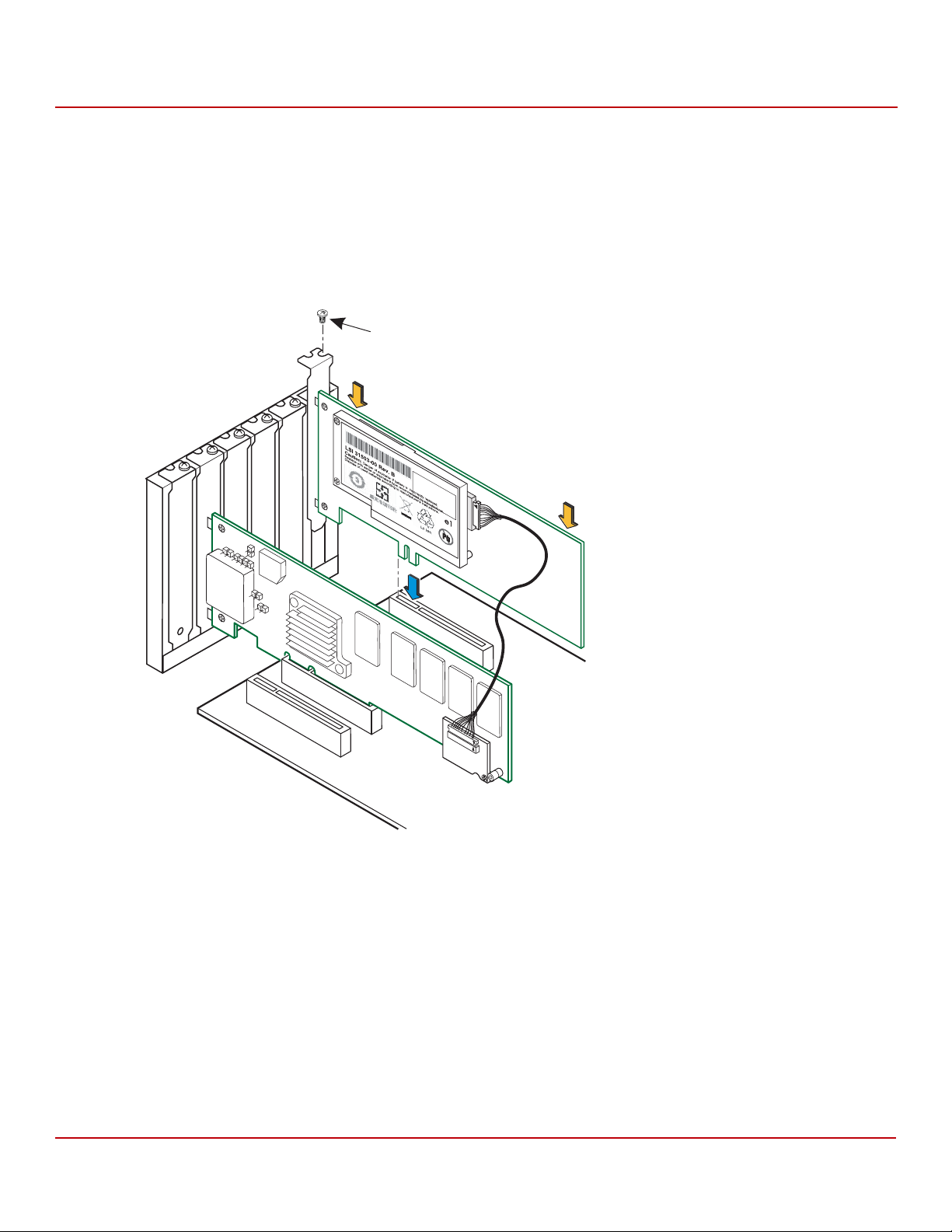
Cache Backup Products for MegaRAID SAS+SATA RAID Controllers User Guide
Screw
Press
Here
Press
Here
3_00722-00
May 2015
2.4.6.5 Installing the Remote Mount Board
Follow these steps to install the remote mount board in the host computer.
1. With the power to the chassis still turned off, and the power cords unplugged, make sure that the chassis is
grounded and has no AC power.
2. Insert the remote mount board in a PCIe slot on the motherboard, as shown in the following figure.
3. Press down gently, but firmly, to seat the board correctly in the slot.
Figure 35 Installing the Remote Mount Board
Chapter 2: Installing the Cache Backup Products
Installing the LSIiBBU07 Unit
4. Secure the remote mount board to the computer chassis with the bracket screw.
5. Attach the cables from the external port connectors to the drives.
6. Reinstall the computer cover, and reattach the power cords.
7. Turn on the power to the computer.
Refer to the MegaRAID SAS Software User Guide for information on running the RAID configuration utility and the
MegaRAID SAS Device Driver Installation User Guide for information on installing the software drivers.
Avago Technologies
- 57 -
Page 58

Cache Backup Products for MegaRAID SAS+SATA RAID Controllers User Guide
May 2015
2.5 Installing the LSIiBBU08 Unit
This section explains how to install the LSIiBBU08 unit directly or remotely with your RAID controller. The LSIiBBU08
unit, which is based on Lithium ion (LiON) battery cell technology, can be used in four application modes:
Mode 1: Attach the LSIiBBU08 unit to the board-to-board connector on the following MegaRAID SAS RAID controllers:
MegaRAID SAS 9260-4i
MegaRAID SAS 9260-8i
MegaRAID SAS 9261-8i
MegaRAID SAS 9280-4i4e
MegaRAID SAS 9280-8e
Mode 2: Connect a 12-in. cable (sold separately in a Remote Battery Kit) between a remote LSIiBBU08 unit and the
remote BBU connector on your RAID controller. Reinstall the RAID controller, and mount the LSIiBBU08 unit on the
system chassis or the motherboard. Use this mode with the following MegaRAID SAS RAID controllers:
MegaRAID SAS 9260-4i*
MegaRAID SAS 9260-8i*
MegaRAID SAS 9260-16i
MegaRAID SAS 9261-8i
MegaRAID SAS 9280-4i4e
MegaRAID SAS 9280-8e
MegaRAID SAS 9280-16i4e
MegaRAID SAS 9280-24i4e
Chapter 2: Installing the Cache Backup Products
Installing the LSIiBBU08 Unit
Mode 3: Connect a 12-in. cable (sold separately in a Remote Battery Kit) between a remote LSIiBBU08 unit and a
board-to-board cable adapter card on the RAID controller. Reinstall the RAID controller, and mount the LSIiBBU08 unit
on the system chassis or motherboard. Use this mode with the following MegaRAID SAS RAID controllers:
MegaRAID SAS 8880EM2
MegaRAID SAS 9260-4i
MegaRAID SAS 9260-8i
Mode 4: Connect a 12-in. cable (sold separately in a Remote Battery Kit) between a LSIiBBU08 unit that is on a remote
mount board and a board-to-board cable adapter card on the RAID controller. Reinstall the RAID controller, and then
install the remote mount board. Use this mode with the following MegaRAID SAS RAID controllers:
MegaRAID SAS 8880EM2
MegaRAID SAS 9260-4i
MegaRAID SAS 9260-8i.
WAR NIN G The battery used in this device might present a fire or chemical burn
hazard if mistreated. Do not disassemble, heat above 100 °C, or
incinerate. Dispose of used battery correctly. Keep away from children.
Avago Technologies
- 58 -
Page 59

Cache Backup Products for MegaRAID SAS+SATA RAID Controllers User Guide
Model: BAT 1S1P
WARNING: The battery used in
this device may present a risk of fire or
chemical burn if mistreated. DO NOT
dissemble, heat above 60C, crush or
puncture, short circuit external contacts,
or dispose in fire or water.
85065-00
J1
1
Contains:
Sony US454261A8T Cell
Rechargeable Li-Polymer
Battery Pack
Rating:
3.7V; 1.59Ah; 5.9Wh
Finished in China
BBU P/N: L4-25343-04
BBU S/N:SY02700225SO
Li-ion
2
J2
5
May 2015
2.5.1 Front View and Rear View of the LSIiBBU08 Unit
The following figure shows the front view and the rear view of the LSIiBBU08 unit. (The front view is the side that you
can see after you install the unit on the RAID controller.) Note that the LSIiBBU08 unit combines a battery pack with a
daughtercard. The LSIiBBU08 unit uses screws and standoffs to connect to the controller.
Figure 36 Front View and Rear View of the LSIiBBU08 Unit
Chapter 2: Installing the Cache Backup Products
Installing the LSIiBBU08 Unit
1. J2 Remote Connector
2. J1 Board-to-Board Connector
NOTE Record your controller serial number in a safe location in case you
need to contact Avago.
Avago Technologies
- 59 -
Page 60

Cache Backup Products for MegaRAID SAS+SATA RAID Controllers User Guide
May 2015
2.5.2 Installing the LSIiBBU08 Unit Directly on the RAID Controller
This section describes how to install the LSIiBBU08 unit directly on the MegaRAID SAS 9280-8e RAID controller. You
can connect the LSIiBBU08 unit in the same way to the other MegaRAID SAS RAID controllers that use this iBBU. For
information about the BBU connectors on these controllers, refer to the 6Gb/s MegaRAID SAS RAID Controllers
User Guide.
Perform the following tasks in order:
1. Remove the RAID controller from the computer. For this procedure, see Section 2.5.2.1, Removing the RAID
Controller from the Computer, on page 60.
2. Install the LSIiBBU08 Unit on the RAID controller. For this procedure, see Section 2.5.2.2, Installing the LSIiBBU08
Unit Directly on a RAID Controller, on page 61.
3. Reinstall the RAID controller. For this procedure, see Section 2.5.2.3, Reinstalling the RAID Controller on the
Motherboard, on page 62.
CAUTION Electrostatic discharge can damage the LSIiBBU08 unit and the
MegaRAID SAS RAID controller. Make sure that you install the
LSIiBBU08 unit at an ESD-safe workstation that meets the
requirements of EIA-625 (Requirements For Handling Electrostatic
Discharge Sensitive Devices). When you install the LSIiBBU08 unit,
follow the ESD-recommended practices in the latest revision of the
IPC-A-610 (Acceptability of Electronic Assemblies) standard.
Chapter 2: Installing the Cache Backup Products
Installing the LSIiBBU08 Unit
2.5.2.1 Removing the RAID Controller from the Computer
Follow these steps to remove the RAID controller from the computer.
1. Turn off the power, and unplug the power cords.
2. Ground yourself, and make sure that the system is grounded.
3. Remove the cover from the computer according to the instructions in the system user’s manual to allow access to
the controller.
4. Unplug all cables from the controller, remove the screw that attaches the bracket to the computer chassis, and
carefully remove the controller from the slot.
5. Place the controller on a flat, clean, static-free surface, and continue with the next procedure.
Avago Technologies
- 60 -
Page 61

Cache Backup Products for MegaRAID SAS+SATA RAID Controllers User Guide
85065-01
J6B1
Model: BAT1S1P
WARNING:
The batteryused in
thisdevice may present a risk of fire or
chemical burn if mistreated.DO NOT
dissemble, heat above60C, crush or
puncture,short circuit external contacts,
or dispose in fire or water.
C
o
n
ta
in
s
:
S
o
n
y
U
S
4
5
4
2
6
1
A
8
T
C
e
ll
R
e
c
h
a
r
g
e
a
b
le
L
i-
P
o
ly
m
e
r
B
a
tte
r
y
P
a
c
k
R
a
tin
g
:
3
.7
V
; 1
.
5
9
A
h
;
5
.
9
W
h
F
i
n
is
h
e
d
in
C
h
in
a
B
B
U
P
/N
: L4-25
34
3-04
B
B
U
S
/N
:S
Y
027
00
225
S
O
L
i-ion
May 2015
2.5.2.2 Installing the LSIiBBU08 Unit Directly on a RAID Controller
Follow these steps to install the LSIiBBU08 unit on the front of the MegaRAID SAS 9280-8e RAID controller.
WAR NIN G If you replace the battery incorrectly, it could explode. Replace the
battery only with the same or equivalent type recommended by the
manufacturer. Dispose of used batteries according to the
manufacturer’s instructions.
1. Ground yourself, and make sure that the system is grounded.
2. Remove the LSIiBBU08 unit from the package.
3. Place the LSIiBBU08 unit front-side-up on a flat, clean, static-free surface.
4. With the front side up, place the RAID controller on a flat, clean, static-free surface.
5. Hold the LSIiBBU08 unit so that the battery side is facing upward and the J1 connector lines up with the J6B1 BBU
connector on the MegaRAID SAS 9280-8e RAID controller, as shown in the following figure.
NOTE Refer to the 6Gb/s MegaRAID SAS RAID Controllers User Guide for the
BBU connectors to use on the other RAID controllers that use the
LSIiBBU08 unit.
Figure 37 Installing the LSIiBBU08 Unit on the MegaRAID SAS 9280-8e RAID Controller
Chapter 2: Installing the Cache Backup Products
Installing the LSIiBBU08 Unit
6. Carefully press the LSIiBBU08 unit onto the RAID controller so that the two connectors are firmly joined.
7. Secure the LSIiBBU08 unit to the RAID controller with the screws and the standoffs in the three screw holes.
The standoffs are threaded at both ends, and a screw goes into each end. The screw threads from the back of the
controller board into the board-to-board standoffs on the bottom of the LSIiBBU08 unit.
NOTE Center the screwdriver carefully to avoid stripping the screw heads.
Do not overtighten the screws.
Avago Technologies
- 61 -
Page 62

Cache Backup Products for MegaRAID SAS+SATA RAID Controllers User Guide
Edge of Motherboard
LSIiBBU08 (Top View)
Bracket Screw
Edge of
Motherboard
85065-02
Press Here
Press Here
M
ode
l: B
A
T1S
1P
Model: BAT1S1P
WARNING:
The battery used in
this device may present a risk of fire or
chemical burn if mistreated. DO NOT
dissemble, heat above 60C, crush or
puncture, short circuit external contacts,
or dispose in fire or water.
WARNING:
The battery used in
this device may present a risk of fire or
chemical burn if mistreated. DO NOT
dissemble, heat above 60C, crush or
puncture, short circuit external contacts,
or dispose in fire or water.
C
o
n
t
a
in
s
:
S
o
n
y
U
S
4
5
4
2
6
1
A
8
T
C
e
ll
R
e
c
h
a
r
g
e
a
b
le
L
i-
P
o
ly
m
e
r
B
a
tte
ry
P
a
c
k
R
a
tin
g
:
3
.
7
V
; 1
.5
9
A
h
;
5
.9
W
h
F
in
is
h
e
d
in
C
h
in
a
Contains:
Sony US454261A8TCell
Rechargeable Li-Polymer
Battery Pack
Rating:
3.7V; 1.59Ah; 5.9Wh
Finished in China
BBU P/N: L4-25343-04
BBU S/N:SY02700225SO
Li-ion
5
May 2015
2.5.2.3 Reinstalling the RAID Controller on the Motherboard
Follow these steps to reinstall the RAID controller on a motherboard.
1. With the power to the chassis still turned off, and the power cords unplugged, make sure that the chassis is
grounded and has no AC power.
2. Install the RAID controller in a PCI Express slot on the motherboard, as shown in the following figure.
NOTE This controller is a PCIe x8 card, and it can operate in x8 or x16 slots.
However, some PCIe slots support only PCIe graphics cards; a
controller installed in one of these slots will not function. Refer to the
guide for your motherboard for information about the PCIe slot.
3. Press down gently, but firmly, to seat the card correctly in the slot.
Figure 38 Reinstalling the MegaRAID SAS 9280-8e RAID Controller
Chapter 2: Installing the Cache Backup Products
Installing the LSIiBBU08 Unit
4. Secure the controller to the computer chassis with the bracket screw.
5. Replace the computer cover and reattach the power cords.
6. Turn on the power to the computer.
Avago Technologies
- 62 -
Page 63

Cache Backup Products for MegaRAID SAS+SATA RAID Controllers User Guide
May 2015
Chapter 2: Installing the Cache Backup Products
Installing the LSIiBBU08 Unit
2.5.3 Connecting the LSIiBBU08 Remotely to the RAID Controller
The following sections describe the three methods you can use to connect the LSIiBBU08 unit remotely to your
MegaRAID SAS RAID controller using the supplied 12-in., 20-pin cable (sold separately in a Remote Battery Kit).
Connect a 12-in. cable between a remote LSIiBBU08 unit and the remote BBU connector on your MegaRAID
controller. Reinstall the RAID controller, and mount the LSIiBBU08 unit on the system chassis or motherboard. See
Section 2.5.4, Connecting the Remote LSIiBBU08 Unit to the BBU Connector on the RAID Controller, on page 63.
Connect a 12-in. cable between a remote LSIiBBU08 unit and a board-to-board adapter card on the RAID
controller. Reinstall the RAID controller, and mount the LSIiBBU08 unit on the system chassis or motherboard. See
Section 2.5.5, Connecting a Remote LSIiBBU08 Unit on the System Chassis to a Board-to-Board Cable Adapter
Card on the RAID Controller, on page 66.
Connect a 12-in. cable between an LSIiBBU08 unit that is installed on a remote mount board and a
board-to-board adapter card on the RAID controller. Reinstall the RAID controller, and install the remote mount
board. See Section 2.5.5.5, Installing the Remote Mount Board in the Host Computer, on page 70.
The procedures in this section show how to connect the LSIiBBU08 unit remotely to the MegaRAID SAS 9280-8i RAID
controller. You can connect the LSIiBBU08 unit in the same way to the other MegaRAID SAS RAID controllers that use
this iBBU unit.
2.5.4 Connecting the Remote LSIiBBU08 Unit to the BBU Connector on the RAID Controller
This section describes how to connect the LSIiBBU08 unit remotely to the BBU connector on the MegaRAID SAS
9280-8e RAID controller.
To connect the remote LSIiBBU08 unit to the BBU connector on the RAID controller, perform the following tasks
in order:
1. Remove the controller from the computer. See Section 2.5.4.1, Removing the RAID Controller from the Computer.
2. Mount the LSIiBBU08 unit to the chassis.
3. Connect the controller to the remote LSIiBBU08 unit using the 12-in., 20-pin cable and the BBU connector on the
RAID controller (the LSIiBBU08 unit must be mounted inside the chassis within 10 in. of the controller). See
Section 2.5.4.2, Connecting the Cable between the RAID Controller and the Remote LSIiBBU08 Unit.
4. Reinstall the controller. See Section 2.5.4.3, Reinstalling the RAID Controller on the Motherboard, on page 65.
NOTE Because server and workstation chassis vary from vendor to vendor,
there is no standard mounting option that is compatible with the
various system configurations. Therefore, the LSIiBBU08 battery kit, in
combination with the Remote Battery Kit, includes the battery,
daughter card, cable, and standoff, which enable authorized resellers
and chassis manufacturers to customize the location of the remote
battery to provide the most flexibility within various environments.
2.5.4.1 Removing the RAID Controller from the Computer
Follow these steps to remove the RAID controller from the computer.
1. Turn off the power, and unplug the power cords.
2. Ground yourself, and make sure that the system is grounded.
3. Remove the cover from the computer according to the instructions in the system user’s manual to allow access to
the controller.
4. Unplug all cables from the controller, remove the screw that attaches the bracket to the computer chassis, and
carefully remove the controller from the slot.
5. Place the controller on a flat, clean, static-free surface, and continue with the next procedure.
Avago Technologies
- 63 -
Page 64

Cache Backup Products for MegaRAID SAS+SATA RAID Controllers User Guide
85065-03
Model: BAT1S1P
WARNING
:
The batteryused in
thisdevice may present a risk of fire or
chemical burn if mistreated.DO NOT
dissemble, heat above60C, crush or
puncture,short circuit external contacts,
or dispose in fire or water.
WARNING:
The batteryused in
thisdevice may present a risk of fire or
chemical burn if mistreated.DO NOT
dissemble, heat above60C, crush or
puncture,short circuit external contacts,
or dispose in fire or water.
C
ontains
:
S
ony US
45426
1A
8T
C
ell
R
ech
arge
ab
le Li-P
olym
er
Battery P
ac
k
Rating
:
3.7V
; 1.5
9A
h; 5
.9W
h
Finish
ed in
C
hina
Contains:
Sony US454261A8TCell
Rechargeable Li-Polymer
Battery Pack
Rating:
3.7V; 1.59Ah; 5.9Wh
Finished in China
B
B
U
P
/N
:
L
4
2
5
3
4
3
0
4
BBU P/N: L4-25343-04
B
B
U
S
/
N
:
S
Y
0
2
7
0
0
2
2
5
S
O
BBU S/N:SY02700225SO
L
i-
io
n
Li-ion
5
May 2015
Chapter 2: Installing the Cache Backup Products
2.5.4.2 Connecting the Cable between the RAID Controller and the Remote LSIiBBU08 Unit
Follow these steps to connect the LSIiBBU08 unit remotely to the BBU connector on the RAID controller.
1. Ground yourself, and make sure that the system is grounded.
2. Remove the LSIiBBU08 unit from the package.
3. Use the three Phillips-head screws that are provided to secure the LSIiBBU08 unit to the motherboard or the
server chassis.
4. Insert the 20-pin cable connector at one end of the 12-in. cable (included in the Remote Battery Kit) into the
20-pin J2 connector on the LSIiBBU08 unit, as shown in the following figure.
5. Insert the 20-pin cable connector at the other end of the 12-in. cable into the 20-pin J6B1 BBU connector on the
MegaRAID SAS 9280-8e RAID controller, as shown in the following figure.
CAUTION Damage to the battery backup unit will occur when power is applied
to the system if the cable assembly connectors are installed backwards
in either the J6B1 board-to-board connector or the J2 BBU connector.
The cable connectors are polarized, and the keying features of the
connector are designed to allow the connectors to be attached in only
one orientation. The cable end inserts into the connector with only
minimal resistance.
Even with the keying features, if excessive force is used, it is possible
to install these connectors incorrectly. To assist in correct alignment,
the small triangles that designate pin 1 on each connector are marked
in black. Make sure these triangles line up as shown in the
illustrations. The wire that connects to pin 1 of each end of the cable
assembly is yellow on most Avago cables.
Installing the LSIiBBU08 Unit
Figure 39 Connecting the Remote LSIiBBU08 Unit to the MegaRAID SAS 9280-8e RAID Controller
Avago Technologies
- 64 -
Page 65

Cache Backup Products for MegaRAID SAS+SATA RAID Controllers User Guide
85065-04
1
2
2
Edge of
Motherboard
Edge of
Motherboard
Model: BAT1S1P
WARNING:
The batteryused in
thisdevice may present a risk of fire or
chemical burn if mistreated.DO NOT
dissemble, heat above60C, crush or
puncture,short circuit external contacts,
or dispose in fire or water.
WARNING:
The batteryused in
thisdevice may present a risk of fire or
chemical burn if mistreated.DO NOT
dissemble, heat above60C, crush or
puncture,short circuit external contacts,
or dispose in fire or water.
C
on
t
ains
:
S
on
y US
45
42
61A
8
T
C
e
ll
R
ech
arg
e
abl
e Li-P
o
ly
m
e
r
B
att
ery P
ac
k
R
atin
g
:
3.7
V;
1.5
9A
h
; 5
.9
W
h
Fin
is
hed
in C
hina
Contains:
Sony US454261A8TCell
Rechargeable Li-Polymer
Battery Pack
Rating:
3.7V; 1.59Ah; 5.9Wh
Finished in China
B
B
U
P
/
N
:
L
4
2
5
3
4
3
0
4
BBU P/N: L4-25343-04
B
B
U
S
/
N
:
S
Y
0
2
7
0
0
2
2
5
S
O
BBU S/N:SY02700225SO
L
i
io
n
Li-ion
5
May 2015
2.5.4.3 Reinstalling the RAID Controller on the Motherboard
Follow these steps to reinstall the RAID controller on a motherboard.
1. With the power to the chassis still turned off, and the power cords unplugged, make sure that the chassis is
grounded and has no AC power.
2. Insert the RAID controller in a PCIe slot on the motherboard, as shown in the following figure.
NOTE This controller is a PCIe x8 card, and it can operate in x8 or x16 slots.
However, some PCIe slots support only PCIe graphics cards; a
controller installed in one of these slots will not function. Refer to the
guide for your motherboard for information about the PCIe slot.
3. Press down gently, but firmly, to seat the card correctly in the slot.
Figure 40 Reinstalling the RAID Controller
Chapter 2: Installing the Cache Backup Products
Installing the LSIiBBU08 Unit
4. Secure the controller to the computer chassis with the bracket screw.
5. Attach the cables from the external port connectors to the drives.
6. Replace the computer cover, and reattach the power cords.
7. Turn on the power to the computer.
Avago Technologies
- 65 -
Page 66

Cache Backup Products for MegaRAID SAS+SATA RAID Controllers User Guide
May 2015
Chapter 2: Installing the Cache Backup Products
Installing the LSIiBBU08 Unit
2.5.5 Connecting a Remote LSIiBBU08 Unit on the System Chassis to a Board-to-Board Cable Adapter Card on the RAID Controller
This section describes how to connect a 12-in. cable (sold separately in a Remote Battery Kit) between a remote
LSIiBBU08 unit and a board-to-board adapter card on the MegaRAID SAS 9260-8i RAID controller. You can connect the
LSIiBBU08 unit in the same way to the other MegaRAID SAS RAID controllers that use this iBBU unit.
Perform the following tasks in order:
1. Remove the RAID controller from the computer. See Section 2.5.5.1, Removing the RAID Controller from the Host
Computer, on page 66.
2. Install the board-to-board adapter card on the RAID controller. See Section 2.5.5.2, Installing the Interposer Card
on the Controller, on page 67.
3. Mount the LSIiBBU08 unit to the chassis.
4. Connect the cable between the board-to-board adapter card on the RAID controller and the LSIiBBU08 unit on
the system chassis. See Section 2.5.5.3, Connecting the Cable Between the Interposer Card and the LSIiBBU08
Unit, on page 68.
5. Reinstall the RAID controller. See Section 2.5.5.4, Reinstalling the Controller in the Host Computer, on page 69.
NOTE Because server and workstation chassis vary from vendor to vendor,
no standard mounting option exists that is compatible with the
various system configurations. The LSIiBBU08 battery kit, in
combination with the Remote Battery Kit, includes the battery,
daughter card, cable, and standoff. This combination enables
authorized resellers and chassis manufacturers to customize the
location of the remote battery to provide the most flexibility within
various environments.
2.5.5.1 Removing the RAID Controller from the Host Computer
Follow these steps to remove the RAID controller from the host computer.
1. Turn off the power, and unplug the power cords.
2. Ground yourself, and make sure that the system is grounded.
3. Remove the cover from the computer according to the instructions in the system user’s manual to allow access to
the controller.
4. Unplug all cables from the controller, remove the screw that attaches the bracket to the computer chassis, and
carefully remove the controller from the slot.
5. Place the controller on a flat, clean, static-free surface, and continue with the next procedure.
Avago Technologies
- 66 -
Page 67

Cache Backup Products for MegaRAID SAS+SATA RAID Controllers User Guide
85039-07
May 2015
2.5.5.2 Installing the Interposer Card on the Controller
Follow these steps to install the interposer card on the controller, as shown in the following figure.
1. With the controller on a flat, clean, static-free surface, ground yourself, and make sure that the system
is grounded.
2. Remove the interposer card, standoff, and screws from the package.
3. Place the standoff on the controller so that the bottom side is over the screw hole next to the JT3 BBU connector
on the controller.
4. Use one of the screws to secure the standoff to the controller.
NOTE Center the screwdriver carefully to avoid stripping the screw head.
Do not overtighten the screws.
5. Hold the interposer card so that the J2 board-to-board connector on the interposer card lines up with the JT3
board-to-board connector on the controller.
6. Carefully press the J2 connector on the interposer card into the JT3 connector on the controller so that the two
connectors are firmly joined.
The connectors fit only when they are in the correct alignment.
7. Use the other screw to secure the interposer card to the controller and continue with the next procedure.
Figure 41 Connecting the Interposer Card to the MegaRAID SAS 9260-8i RAID Controller
Chapter 2: Installing the Cache Backup Products
Installing the LSIiBBU08 Unit
Avago Technologies
- 67 -
Page 68

Cache Backup Products for MegaRAID SAS+SATA RAID Controllers User Guide
85039-08
May 2015
2.5.5.3 Connecting the Cable Between the Interposer Card and the LSIiBBU08 Unit
Follow these steps to connect the cable between the interposer card on the RAID controller and the LSIiBBU08 unit.
1. Mount the LSIiBBU08 unit to the chassis of your computer based on the location and the type of
mounting option.
2. With the controller on a flat, clean, static-free surface, ground yourself, and make sure that the system
is grounded.
3. Remove the cable included in the Remote Battery Kit (sold separately).
4. Insert one end of the cable into the 20-pin J2 connector on the LSIiBBU08 unit and the other end into the 20-pin
J1 connector on the interposer card, as shown in the following figure.
Align the black triangles on the connectors to make sure that the connectors are connected correctly.
CAUTION The cable connectors are polarized and can be inserted into the
connectors on the interposer card and the LSIiBBU08 unit only if the
rails on the cable connectors align with the slots on the other
connectors. Do not force the cable into the 20-pin connectors. The
cable end inserts into the connector with minimal resistance.
Figure 42 Connecting the LSIiBBU08 Unit Remotely to the Interposer Card
Chapter 2: Installing the Cache Backup Products
Installing the LSIiBBU08 Unit
Avago Technologies
- 68 -
Page 69

Cache Backup Products for MegaRAID SAS+SATA RAID Controllers User Guide
Edge of Motherboard
Bracket Screw
Edge of
Motherboard
Press Here
85039-09
Press Here
May 2015
2.5.5.4 Reinstalling the Controller in the Host Computer
Follow these steps to install the RAID controller in the computer.
1. With the power to the chassis still turned off, and the power cords unplugged, make sure that the chassis is
grounded and has no AC power.
2. Insert the RAID controller in a PCIe slot on the motherboard, as shown in the following figure.
NOTE This controller is a PCIe x8 card, and it can operate in x8 or x16 slots.
However, some PCIe slots support only PCIe graphics cards; a
controller installed in one of these slots will not function. Refer to the
guide for your motherboard for information about the PCIe slot.
3. Press down gently, but firmly, to seat the card correctly in the slot.
Figure 43 Reinstalling the RAID Controller
Chapter 2: Installing the Cache Backup Products
Installing the LSIiBBU08 Unit
4. Secure the controller to the computer chassis with the bracket screw.
5. Replace the computer cover and reattach the power cords.
6. Turn on the power to the computer.
Refer to the MegaRAID SAS Software User Guide for information on running the RAID configuration utility and the
MegaRAID SAS Device Driver Installation User Guide for information on installing the software drivers.
Avago Technologies
- 69 -
Page 70

Cache Backup Products for MegaRAID SAS+SATA RAID Controllers User Guide
85085-04
LSI 31504-00 Rev. B
Li-ion
CAUTION: Danger of explosion if batteryis incorrectly replaced.
Replacewith same or equivalent type recommended by manufacturer.
Dispose of usedbatteries according to manufacturer’s instructions.
Pb
e1
5
Press
Here
Press
Here
Screw
May 2015
2.5.5.5 Installing the Remote Mount Board in the Host Computer
Follow these steps to install the remote mounting board in the computer.
1. With the power to the chassis still turned off, and the power cords unplugged, make sure that the chassis is
grounded and has no AC power.
2. Insert the remote mounting board in a PCIe slot on the motherboard, as shown in the following figure.
NOTE Some PCIe slots support only PCIe graphics cards; if the remote
mounting board is installed in one of these slots, the board will not
function. Refer to your computer documentation for information
about the PCIe slot.
3. Press down gently, but firmly, to seat the board correctly in the slot.
Figure 44 Installing the Remote Mounting Board
Chapter 2: Installing the Cache Backup Products
Installing the LSIiBBU08 Unit
4. Secure the remote mounting board to the computer chassis with the bracket screw.
5. Reinstall the computer cover and reattach the power cords.
6. Turn on the power to the computer.
Refer to the MegaRAID SAS Software User Guide for information on running the RAID configuration utility and the
MegaRAID SAS Device Drivers Installation User Guide for information on installing the software drivers.
Avago Technologies
- 70 -
Page 71

Cache Backup Products for MegaRAID SAS+SATA RAID Controllers User Guide
May 2015
Chapter 2: Installing the Cache Backup Products
Installing the LSIiBBU08 Unit
2.5.6 Connecting the LSIiBBU08 Unit on a Remote Mount Board to a Board-to Board Cable Adapter Card on the RAID Controller
This section describes how to connect a 12-in. cable (sold separately in a Remote Battery Kit) between a remote
LSIiBBU08 unit and a board-to-board adapter card on the MegaRAID SAS 9260-8i RAID controller. You can connect the
LSIiBBU08 unit in the same way to the other MegaRAID SAS RAID controllers that use this iBBU unit.
Perform the following tasks in order:
1. Remove the RAID controller from the computer. See Section 2.5.6.1, Removing the RAID Controller from the Host
Computer, on page 71.
2. Install the board-to-board adapter card on the RAID controller. See Section 2.5.6.2, Installing the Interposer Card
on the Controller, on page 72.
3. Connect the cable between the board-to-board adapter card on the RAID controller and the LSIiBBU08 unit on
the remote mount board. See Section 2.5.6.3, Connecting the Cable Between the LSIiBBU08 Unit on the Remote
Mount Board and the Adapter Card on the RAID Controller, on page 73.
4. Reinstall the RAID controller. For this procedure, see Section 2.5.6.4, Reinstalling the RAID Controller, on page 74.
5. Install the remote mount board. See Section 2.5.6.5, Installing the Remote Mount Board on page 75.
2.5.6.1 Removing the RAID Controller from the Host Computer
Follow these steps to remove the RAID controller from the computer.
1. Turn off the power, and unplug the power cords.
2. Ground yourself, and make sure that the system is grounded.
3. Remove the cover from the computer, according to the instructions in the system user’s manual, to allow access
to the controller.
4. Unplug all cables from the controller, remove the screw that attaches the bracket to the computer chassis, and
carefully remove the controller from the slot.
5. Place the controller on a flat, clean, static-free surface, and continue with the next procedure.
Avago Technologies
- 71 -
Page 72

Cache Backup Products for MegaRAID SAS+SATA RAID Controllers User Guide
85039-07
May 2015
2.5.6.2 Installing the Interposer Card on the Controller
Follow these steps to install the interposer card on the controller, as shown in the following figure.
1. With the controller on a flat, clean, static-free surface, ground yourself, and make sure that the system is
grounded.
2. Remove the interposer card, standoff, and screws from the package.
3. Place the standoff on the controller so that the bottom side is over the screw hole next to the JT3 BBU connector
on the controller.
4. Use one of the screws to secure the standoff to the controller.
NOTE Center the screwdriver carefully to avoid stripping the screw head.
Do not overtighten the screws.
5. Hold the interposer card so that the J2 board-to-board connector on the interposer card lines up with the JT3
board-to-board connector on the controller.
6. Carefully press the J2 connector on the interposer card into the JT3 connector on the controller so that the two
connectors are firmly joined.
The connectors fit only when they are in the correct alignment.
7. Use the other screw to secure the interposer card to the controller and continue with the next procedure.
Figure 45 Connecting the Interposer Card to the MegaRAID SAS 9260-8i RAID Controller
Chapter 2: Installing the Cache Backup Products
Installing the LSIiBBU08 Unit
Avago Technologies
- 72 -
Page 73

Cache Backup Products for MegaRAID SAS+SATA RAID Controllers User Guide
3_00749-00
M
o
d
e
l:
B
A
T1
S
1
P
Model:
B
A
T1
S1
P
W
A
RN
IN
G
:
T
h
e
b
a
t
te
ry
u
s
e
d
i
n
th
is
d
evic
e
m
a
y
p
r
e
s
en
t
a
r
is
k
o
f fir
e
o
r
c
h
e
m
ic
a
l b
u
rn
i
f m
is
tr
e
a
te
d
. D
O
N
O
T
d
is
s
e
m
b
l
e
,
h
e
a
t
a
b
o
v
e
6
0
C
, c
ru
s
h
o
r
p
u
n
c
tu
r
e
, s
h
o
rt c
irc
u
it e
x
te
r
n
a
l
c
o
n
ta
c
ts
,
o
r
d
is
p
o
s
e
in
fir
e
o
r w
a
te
r.
W
A
R
N
I
N
G:
T
he
b
a
t
t
e
ry
us
e
d i
n
this
d
ev
i
c
e
m
a
y
p
re
s
en
t
a
r
i
s
k
o
f f
i
r
e
o
r
c
h
em
i
c
al
b
u
r
n
if
m
i
s
tr
e
a
ted
.
D
O
N
O
T
dis
s
em
b
l
e
,
h
e
at
a
b
ov
e
6
0
C,
c
r
u
s
h
or
p
u
nc
tu
r
e
,
s
h
o
r
t
c
i
r
c
u
it
e
x
te
r
n
a
l
c
o
n
t
a
c
ts
,
o
r
d
is
po
s
e i
n
f
ir
e
o
r
w
a
t
e
r
.
C
o
n
ta
i
n
s
:
So
n
y
U
S
454
2
6
1
A
8
T
C
e
l
l
R
e
c
h
a
r
g
e
a
b
l
e
Li
P
o
l
ym
e
r
Ba
t
t
e
r
y
P
a
c
k
R
a
t
i
n
g:
3
.
7
V
;
1
.
5
9
A
h
;
5.
9W
h
F
i
n
i
s
h
e
d
i
n
C
h
i
n
a
Conta
ins
:
S
ony
US
4542
61
A
8T
Cel
l
Rechar
geab
le
Li-
P
olym
er
B
at
te
r
y
P
ac
k
Rat
ing
:
3.
7V; 1
.5
9Ah;
5.
9W
h
F
inish
ed in
Ch
in
a
B
B
U
P
/
N
:
L4
-
2
5
343
-
04
BBU
P/
N
: L
4-
2
5
3
4
3
-0
4
B
B
U
S
/
N
:
SY
0
2
7
0
02
2
5
S
O
BBU
S/
N
:SY02
7
0
02
25
S
O
L
i
-
io
n
L
i-
io
n
5
May 2015
Chapter 2: Installing the Cache Backup Products
Installing the LSIiBBU08 Unit
2.5.6.3 Connecting the Cable Between the LSIiBBU08 Unit on the Remote Mount Board and the Adapter Card on the RAID Controller
Follow these steps to connect the cable between the LSIiBBU08 unit on the remote mount board and the
board-to-board adapter card on the RAID controller.
1. With the controller on a flat, clean, static-free surface, ground yourself, and make sure that the system
is grounded.
2. Insert the 20-pin cable connector at one end of the 12-in. cable into the 20-pin J2 cable connector on the
LSIiBBU08 unit on the remote mount board, as shown in the following figure.
3. Insert the 20-pin cable connector at the other end of the 12-in. cable into the 20-pin J1 connector on the
board-to-board cable adapter card that is installed on the RAID controller, as shown in the following figure.
Black triangles on the connectors help you install the connectors correctly. Insert the cable connectors into the
controller connector and the iBBU connector so that the black triangles are aligned, as shown in the
following figure.
CAUTION Damage to the battery backup unit will occur when power is applied
to the system if the cable assembly connectors are installed backwards
in either the J1 connector on the board-to-board cable adapter card or
on the J2 BBU connector. The cable connectors are polarized, and the
keying features of the connector are designed to allow the connectors
to be attached in only one orientation. The cable end inserts into the
connector with only minimal resistance.
Even with the keying features, if excessive force is used, it is possible
to install these connectors incorrectly. To assist in correct alignment,
the small triangles that designate pin 1 on each connector are marked
in black. Make sure these triangles line up as shown in the
illustrations. The wire that connects to pin 1 of each end of the cable
assembly is yellow on most Avago cables.
Figure 46 Connecting the LSIiBBU08 Unit on the Remote Mount Board to the Board-to-Board Cable Adapter
Avago Technologies
- 73 -
Page 74

Cache Backup Products for MegaRAID SAS+SATA RAID Controllers User Guide
Edge of Motherboard
Screw
Press
Here
Press
Here
3_00750-00
M
o
d
e
l
:
B
A
T1
S
1
P
Model: BA
T1
S1
P
WA
R
NIN
G:
T
h
e
b
a
tte
r
y
u
s
e
d
in
th
i
s
d
e
v
ic
e
m
a
y
p
re
s
e
n
t
a
r
is
k
o
f fire
o
r
c
h
e
m
ic
a
l
b
u
r
n
if
m
is
t
re
a
te
d
. D
O
N
O
T
d
is
s
e
m
b
l
e
, h
e
a
t a
b
o
v
e
6
0
C
,
c
ru
s
h
o
r
p
u
n
c
tu
re
, s
h
o
r
t
c
ir
c
u
i
t e
x
te
r
n
a
l
c
on
ta
c
t
s
,
o
r
d
is
p
o
s
e
in
fir
e
o
r
w
a
t
e
r
.
W
A
RN
IN
G:
T
h
e
b
at
te
ry
u
s
e
d
in
th
i
s
d
e
v
ic
e
m
a
y
p
re
s
e
n
t
a
ris
k
o
f
f
i
re
o
r
c
h
e
m
ic
a
l
b
u
r
n
if
m
is
t
re
a
te
d
. D
O
N
O
T
d
i
s
s
e
m
b
l
e
,
h
e
a
t
a
b
o
v
e
6
0
C
,
c
ru
s
h
o
r
p
u
n
c
tu
re
,
s
h
o
r
t
c
ir
c
u
it
e
x
te
rn
a
l
c
o
n
t
a
c
ts
,
o
r
d
i
s
p
o
s
e
in
fi
re
o
r
w
a
t
e
r
.
C
o
n
t
a
i
n
s
:
S
o
n
y
U
S
45
4
26
1A
8
T
C
e
l
l
R
ec
ha
r
ge
a
b
l
e
L
i
P
o
l
y
me
r
B
a
t
t
e
r
y
P
a
c
k
R
at
i
ng
:
3.
7
V
;
1.
5
9
A
h
;
5
.
9
W
h
F
i
n
i
sh
e
d
i
n
C
h
i
n
a
C
on
tains
:
S
o
ny U
S
4
54
2
6
1
A
8T
C
el
l
R
ech
a
r
ge
a
b
le
Li-Po
ly
mer
B
atte
r
y Pac
k
R
a
tin
g
:
3
.7
V
; 1
.59
A
h
; 5.9W
h
Fin
is
h
e
d
in
Ch
in
a
B
BU
P
/
N
:
L
4
-
25
3
4
3
-
0
4
BB
U P
/N: L4-25343-0
4
B
B
U
S
/
N
:
SY
0
2
7
0
0
22
5
S
O
BB
U S
/N:S
Y02700225S
O
L
i-
i
o
n
Li-
ion
5
May 2015
2.5.6.4 Reinstalling the RAID Controller
Follow these steps to reinstall the RAID controller in the computer.
1. With the power to the chassis still turned off and the power cords unplugged, make sure that the chassis is
grounded and has no AC power.
2. Insert the RAID controller into a PCIe slot on the motherboard, as shown in the following figure.
NOTE This controller is a PCIe x8 card, and it can operate in x8 or x16 slots.
However, some PCIe slots support only PCIe graphics cards; a
controller installed in one of these slots will not function. Refer to the
guide for your motherboard for information about the PCIe slot.
3. Press down gently, but firmly, to seat the controller correctly in the slot.
4. Secure the controller to the computer chassis with the bracket screw.
Figure 47 Reinstalling the RAID Controller
Chapter 2: Installing the Cache Backup Products
Installing the LSIiBBU08 Unit
Avago Technologies
- 74 -
Page 75

Cache Backup Products for MegaRAID SAS+SATA RAID Controllers User Guide
Press
Here
3_00751-00
Screw
Press
Here
M
o
d
e
l
:
B
A
T1
S
1
P
Model:
BA
T
1
S1
P
WA
R
NIN
G:
T
h
e b
a
tte
r
y
u
s
e
d
in
th
i
s
d
e
v
ic
e
m
a
y
p
r
e
s
e
n
t
a
ris
k
o
f
fir
e
o
r
c
h
e
m
i
c
a
l
b
ur
n
if
m
is
trea
te
d
.
D
O
N
O
T
d
is
s
e
m
b
le
, he
a
t
a
bo
v
e
6
0
C
,
c
ru
s
h
o
r
p
u
n
c
tu
re
,
s
h
o
rt
c
i
r
c
u
it e
x
te
rn
a
l
c
o
n
tac
ts
,
o
r d
is
p
o
s
e
i
n
fire
o
r w
a
te
r
.
W
A
RN
ING:
T
h
e
b
a
t
t
e
r
y
u
s
e
d
i
n
t
h
is
d
e
v
ic
e
m
a
y
p
re
s
e
nt
a
r
i
s
k
o
f
f
i
r
e
o
r
c
h
em
i
ca
l
b
u
r
n
if
m
i
st
r
e
a
t
e
d
.
D
O
N
O
T
d
i
s
s
emb
le
, h
e
a
t
ab
o
v
e
6
0
C
,
c
ru
s
h
o
r
p
u
n
c
t
u
re,
s
h
o
r
t
c
ir
c
u
i
t
e
x
te
rn
a
l
c
on
t
a
c
t
s
,
o
r d
i
s
p
os
e
in
fire
o
r w
a
te
r
.
C
o
n
t
ai
n
s
:
S
o
n
y
U
S
4
5
4
2
6
1
A
8
T
C
e
l
l
R
e
c
h
a
r
g
e
ab
l
e
L
i
P
o
l
y
me
r
B
a
t
t
e
ry
P
a
c
k
R
a
t
i
n
g
:
3.
7
V
;
1.
5
9
A
h
;
5
.
9
W
h
F
i
n
i
s
h
e
d
i
n
C
h
i
n
a
C
on
tain
s
:
S
o
n
y U
S
45
4
26
1
A
8T
C
el
l
R
ech
a
r
g
eab
le
Li-Poly
m
er
B
a
tte
r
y Pac
k
R
atin
g
:
3
.7
V
; 1
.59
A
h
; 5
.9W
h
Fin
is
he
d
in
Ch
in
a
B
B
U
P
/
N
:
L4
-
2
53
4
3
-04
B
BU
P
/
N:
L
4
-
2
5
34
3
-
04
BB
U
S
/
N
:
SY
0
2
7
0
022
5
S
O
B
BU
S
/
N:
SY
02
700
2
2
5
S
O
Li-
i
o
n
L
i
-
i
o
n
5
May 2015
2.5.6.5 Installing the Remote Mount Board
Follow these steps to install the remote mount board in the computer.
1. With the power to the chassis still turned off, and the power cords unplugged, make sure that the chassis is
grounded and has no AC power.
2. Insert the remote mount board in a PCIe slot on the motherboard, as shown in the following figure.
NOTE This controller is a PCIe x8 card, and it can operate in x8 or x16 slots.
However, some PCIe slots support only PCIe graphics cards; a
controller installed in one of these slots will not function. Refer to the
guide for your motherboard for information about the PCIe slot.
3. Press down gently, but firmly, to seat the board correctly in the slot.
Figure 48 Installing the Remote Mount Board
Chapter 2: Installing the Cache Backup Products
Installing the LSIiBBU08 Unit
4. Secure the remote mount board to the computer chassis with the bracket screw.
5. Attach the cables from the external port connectors to the drives.
6. Reinstall the computer cover, and reattach the power cords.
7. Turn on the power to the computer.
Refer to the MegaRAID SAS Software User Guide for information on running the RAID configuration utility and the
MegaRAID SAS Device Driver Installation User Guide for information on installing the software drivers.
Avago Technologies
- 75 -
Page 76

Cache Backup Products for MegaRAID SAS+SATA RAID Controllers User Guide
May 2015
2.6 Installing the LSIiBBU09 Unit
The Avago MegaRAID LSIiBBU09 product is an intelligent battery backup unit (iBBU), based on Lithium ion (LiON)
battery cell technology. The LSIiBBU09 unit protects the integrity of the cached data on a MegaRAID RAID controller
for up to 48 hours (depending on the derated retention time selected) in case of a complete AC power failure or a brief
power outage.
The LSIiBBU09 unit connects directly to the following MegaRAID SAS RAID controllers:
MegaRAID SAS 9266-4i
MegaRAID SAS 9266-8i
MegaRAID SAS 9271-4i
MegaRAID SAS 9271-8i
MegaRAID SAS 9271-8iCC
The LSIiBBU09 unit connects remotely to a transportable memory module on the following MegaRAID SAS
RAID controllers:
MegaRAID SAS 9265-8i
MegaRAID SAS 9266-4i
MegaRAID SAS 9266-8i
MegaRAID SAS 9270-8i
MegaRAID SAS 9271-4i
MegaRAID SAS 9271-8i
MegaRAID SAS 9271-8iCC
MegaRAID SAS 9285-8e
MegaRAID SAS 9286-8e
Chapter 2: Installing the Cache Backup Products
Installing the LSIiBBU09 Unit
You can connect the remote LSIiBBU09 unit by cable to a transportable memory module in the following way:
Connect the LSIiBBU09 unit by cable to an RCM01 module on the RAID controller, and then mount the LSIiBBU09
unit on the system chassis. Follow the steps in Section 2.6.3, Connecting a Remote LSIiBBU09 Unit on the System
Chassis to a RCM01 Module on a RAID Controller, on page 81.
WAR NIN G The battery used in this device might present a fire or chemical burn
hazard if mistreated. Do not disassemble, heat above 100 °C, or
incinerate. Dispose of used battery correctly. Keep away from children.
Avago Technologies
- 76 -
Page 77

Cache Backup Products for MegaRAID SAS+SATA RAID Controllers User Guide
LSI CORP.© 2010 ALL RIGHTS RESERVED
Pb e1
ASSEMBLED
IN CHINA
RoHS
AsRPCB
E248037
94V0
Li Ion
Model: BAT1S1P-A
BBU P/N: L4-25407-00
BBU S/N: SAYWWSSSSSss
Contains:
Sony US454261A8TCell
Rechargeable Li-Polymer
Battery Pack
Rating:
3.7V; 1.59 Ah; 5.9Wh
Finished in China
WARNING: The battery used in this
device may present a risk of fire or
chemical burn if mistreated. DO NOT
disassemble, heat above 60C, crush or
puncture, short circuit external contacts,
or dispose of in fire or water.
MH29577
Li-ion
!
L3-25407-00A
Top View
Bottom View
85083-00
1
2
May 2015
2.6.1 Top View and Bottom View of the LSIiBBU09 Unit
The following figure shows the top view and the bottom view of the LSIiBBU09 unit. (The top view is the side that you
can see after you install the LSIiBBU09 unit on the system chassis or when the unit is installed on a remote
mounting board.)
Figure 49 Top View and Bottom View of the LSIiBBU09 Unit
Chapter 2: Installing the Cache Backup Products
Installing the LSIiBBU09 Unit
1. Remote Cable Connector
2. Board-to-Board Connector
NOTE Record your controller serial number in a safe location in case you
need to contact Avago.
Avago Technologies
- 77 -
Page 78

Cache Backup Products for MegaRAID SAS+SATA RAID Controllers User Guide
May 2015
Chapter 2: Installing the Cache Backup Products
2.6.2 Attaching a LSIiBBU09 Unit Directly to a MegaRAID SAS 9266 RAID Controller
This section describes how to connect the MegaRAID LSIiBBU09 unit directly to a MegaRAID SAS 9266-4i RAID
controller or a MegaRAID SAS 9266-8i RAID controller.
WAR NIN G The battery used in this device might present a fire or chemical burn
hazard if mistreated. Do not disassemble, heat above 100 °C (212 °F) or
incinerate. Dispose of used battery correctly. Keep away from children.
Perform the following tasks described in this section to attach the LSIiBBU09 unit directly to the MegaRAID SAS 9266
RAID controller.
1. Remove the RAID controller from the computer. See Section 2.6.2.1, Removing the RAID Controller from the
Computer.
2. Attach the LSIiBBU09 unit directly to the RAID controller. See Section 2.6.2.2, Attaching the LSIiBBU09 Unit to the
RAID Controller.
3. Reinstall the RAID controller on the motherboard. See Section 2.5.2.3, Reinstalling the RAID Controller on the
Motherboard, on page 62.
CAUTION Electrostatic discharge (ESD) can damage the LSIiBBU09 unit and the
RAID controller. Make sure that you install the LSIiBBU09 unit at an
ESD-safe workstation that meets the EIA-625 standard. When
you install the LSIiBBU09 unit, follow the ESD-recommended practices
in the latest revision of the IPC-A-610 (Acceptability of Electronic
Assemblies) standard.
Installing the LSIiBBU09 Unit
2.6.2.1 Removing the RAID Controller from the Computer
Follow these steps to remove the RAID controller from the computer.
1. Turn off the power, and unplug the power cords.
2. Ground yourself, and make sure that the system is grounded.
3. Remove the cover from the computer, according to the instructions in the system user’s manual, to allow access
to the controller.
4. Unplug all cables from the controller, remove the screw that attaches the bracket to the computer chassis, and
carefully remove the controller from the slot.
5. Place the controller on a flat, clean, static-free surface, and continue with the next procedure.
Avago Technologies
- 78 -
Page 79

Cache Backup Products for MegaRAID SAS+SATA RAID Controllers User Guide
3_00896-00
J1A3
LSIiBBU09
May 2015
2.6.2.2 Attaching the LSIiBBU09 Unit to the RAID Controller
Follow these steps to attach the LSIiBBU09 unit directly to the front of the RAID controller.
WAR NIN G There is danger of an explosion if the battery is incorrectly replaced.
Replace the battery only with the same or equivalent type
recommended by the manufacturer. Dispose of used batteries
according to the manufacturer’s instructions.
1. Ground yourself, and make sure that the system is grounded.
2. Remove the LSIiBBU09 unit from the package.
3. Place the LSIiBBU09 unit front-side-up on a flat, clean, static-free surface.
4. Place the RAID controller front-side up on a flat, clean, static-free surface.
5. Hold the LSIiBBU09 unit so that the top of the battery is facing upward, and the J1 connector lines up with the
J1A3 BBU connector on the RAID controller, as shown in the following figure.
Figure 50 Attaching the LSIiBBU09 Unit to the RAID Controller
Chapter 2: Installing the Cache Backup Products
Installing the LSIiBBU09 Unit
6. Carefully press the LSIiBBU09 unit onto the RAID controller so that the two connectors are firmly joined.
7. Secure the LSIiBBU09 unit to the RAID controller with the screws and the standoffs in the three screw holes.
The standoffs are threaded at both ends, and a screw goes into each end. The screw threads from the back of the
controller board into the board-to-board standoffs on the bottom of the LSIiBBU09 unit.
NOTE Center the screwdriver carefully to avoid stripping the screw heads.
Do not overtighten the screws.
Avago Technologies
- 79 -
Page 80

Cache Backup Products for MegaRAID SAS+SATA RAID Controllers User Guide
Edge of
Motherboard
PCI Express
Bracket
Screw
Press
Here
Press
Here
3_00891a-00
May 2015
2.6.2.3 Reinstalling the RAID Controller on the Motherboard
Follow these steps to reinstall the RAID controller on a motherboard.
1. Make sure that the power to the chassis is still turned off, the power cords are unplugged, and the chassis is
grounded and has no AC power.
2. Install the RAID controller in a PCI Express slot on the motherboard, as shown in the following figure.
NOTE Some PCI Express slots support only PCI Express graphics cards. A RAID
controller installed in one of these slots will not function. Refer to your
computer documentation for information about the PCI Express slot.
3. Press down gently, but firmly, to seat the card correctly in the slot.
4. Secure the controller to the computer chassis.
Figure 51 Reinstalling the RAID Controller
Chapter 2: Installing the Cache Backup Products
Installing the LSIiBBU09 Unit
5. Replace the computer cover, and reattach the power cords.
6. Turn on the power to the computer.
Avago Technologies
- 80 -
Page 81

Cache Backup Products for MegaRAID SAS+SATA RAID Controllers User Guide
May 2015
Chapter 2: Installing the Cache Backup Products
Installing the LSIiBBU09 Unit
2.6.3 Connecting a Remote LSIiBBU09 Unit on the System Chassis to a RCM01 Module on a RAID Controller
The procedures in this section show how to connect a remote LSIiBBU09 unit on the system chassis to a RCM01
module that is installed on the MegaRAID SAS 9265-8i RAID controller. You can connect the LSIiBBU09 unit in the
same way to the MegaRAID SAS 9285-8e RAID controller and the MegaRAID SAS 9286-8e RAID controller
To connect a remote LSIiBBU09 unit to your RAID controller, perform the following tasks in order.
1. Remove the RAID controller from the host computer. See Section 2.6.3.2, Removing the RAID Controller from the
Host Computer, on page 82.
2. Connect the cable between the RCM01 module and the remote LSIiBBU09 unit. See Section 2.6.3.3, Connecting
the Cable between the RCM01 Module and the Remote LSIiBBU09 Unit, on page 83.
3. Reinstall the RAID controller in the host computer. See Section 2.6.3.4, Reinstalling the RAID Controller in the Host
Computer, on page 84.
NOTE Because server and workstation chassis vary from vendor to vendor,
no standard mounting option exists that is compatible with the
various system configurations. The LSIiBBU09 battery kit, in
combination with the Remote Battery Kit, includes the battery,
daughtercard, cable, and standoff. This combination enables
authorized resellers and chassis manufacturers to customize the
location of the remote battery to provide the most flexibility within
various environments.
Avago Technologies
- 81 -
Page 82

Cache Backup Products for MegaRAID SAS+SATA RAID Controllers User Guide
85075-04
Top View
Bottom View
Board to Board
Connector
Cable Connector
May 2015
2.6.3.1 Top View and Bottom View of the RCM01 Module
The following figure shows the top view and the bottom view of the RCM01 module. (The top view is the side that you
can see when the unit is installed on a RAID controller.)
Figure 52 Top View and Bottom View of the RCM01 Module
Chapter 2: Installing the Cache Backup Products
Installing the LSIiBBU09 Unit
1. Remote Cable Connector
2. Board-to-Board Connector
Record your controller serial number in a safe location in case you need to contact Avago.
2.6.3.2 Removing the RAID Controller from the Host Computer
Follow these steps to remove the RAID controller from the computer.
1. Turn off the power, and unplug the power cords.
2. Ground yourself, and make sure that the system is grounded.
3. Remove the cover from the computer, according to the instructions in the system user’s manual, to allow access
to the controller.
4. Unplug all cables from the controller, remove the screw that attaches the bracket to the computer chassis, and
carefully remove the controller from the slot.
5. Place the controller on a flat, clean, static-free surface, and continue with the next procedure.
Avago Technologies
- 82 -
Page 83

Cache Backup Products for MegaRAID SAS+SATA RAID Controllers User Guide
85083-01
LSICORP. © 2010 ALLRI GHTS RESERVED
Pb e1
ASSEMBLED
INCHINA
RoHS
AsRPCB
E248037
94V0
Li Ion
Model: BAT1S1P-A
BBU P/N: L4-25407-00
BBU S/N: SAYWWSSSSSss
Contains:
Sony US454261A8TCell
RechargeableLi-Polymer
Battery Pack
Rating:
3.7V;1.59 Ah; 5.9Wh
Finishedin China
WARNING: The battery used in this
devicemay present a risk of fire or
chemical burn if mistreated. DO NOT
disassemble, heat above 60C, crush o r
puncture, shortcircuit external contacts,
or disposeof in fire or water.
MH29577
Li-ion
!
L
3
25
4
0
7
0
0
A
May 2015
Chapter 2: Installing the Cache Backup Products
2.6.3.3 Connecting the Cable between the RCM01 Module and the Remote LSIiBBU09 Unit
Follow these steps to connect the cable between the RCM01 module on the RAID controller and the LSIiBBU09 unit.
1. Mount the LSIiBBU09 unit to the chassis of your computer based on the location and the type of
mounting option.
2. With the controller on a flat, clean, static-free surface, ground yourself, and make sure that the system
is grounded.
3. Remove the cable included in the Remote Battery Kit (sold separately).
4. Insert one end of the cable into the 20-pin cable connector on the LSIiBBU09 unit and the other end into the
20-pin cable connector on the RCM01 module, as shown in the following figure.
Align the black triangles on the connectors to make sure that the connectors are connected correctly.
CAUTION The cable connectors are polarized and can be inserted into the cable
connectors on the CVFM02 module and the LSIiBBU09 unit only if the
rails on the cable connectors align with the slots on the other
connectors. Do not force the cable into the 20-pin connectors. The
cable end inserts into the connector with minimal resistance.
Figure 53 Connecting the LSIiBBU09 Unit on the System Chassis to the RCM01 Module on the RAID Controller
Installing the LSIiBBU09 Unit
Avago Technologies
- 83 -
Page 84

Cache Backup Products for MegaRAID SAS+SATA RAID Controllers User Guide
85083-02
Screw
PCI Socket
Edge of
Motherboard
Press
Here
Press
Here
LSI C
ORP
.©
2010
AL
LR
IG
HTS
RE
SERVED
Pb
e1
AS
SEMB
LED
INCH
INA
Ro
HS
AsRP
CB
E248037
94V0
L
i
I
on
M
o
d
el
:B
AT
1S
1
P-A
BB
U
P
/N
:
L
4
-2
54
07-
0
0
BB
U
S
/
N
:S
AY
WW
S
SSS
Ss
s
Con
t
ai
n
s:
So
ny
U
S
4
54
261
A8T
Ce
ll
Recha
r
g
e
ab
l
eL
i-
Po
ly
me
r
Ba
tt
e
r
y
Pa
ck
Rat
i
ng
:
3.
7V;1.5
9
Ah
;
5
.
9
Wh
F
i
n
i
sh
ed
in
Ch
i
n
a
WA
RNING: T
h
e
b
a
t
te
r
y
us
ed
i
nt
hi
s
d
e
vi
c
em
a
yp
re
sent
a
r
i
sko
f
f
ire o
r
chem
ic
al
bu
r
n
if
m
is
tr
e
a
ted
.D
O
N
O
T
d
isa
ss
em
bl
e,
h
ea
t
ab
o
ve
6
0
C
,crush
o
r
p
u
n
ct
ur
e
,
s
hortc
i
rc
ui
te
xt
e
rn
a
l
c
onta
c
ts
,
o
r
d
i
s
po
s
eo
fi
nf
i
re
o
r
w
a
te
r
.
MH2
9
577
L
i
-i
on
!
L3
-25
40
7-
00
A
May 2015
2.6.3.4 Reinstalling the RAID Controller in the Host Computer
Follow these steps to reinstall the RAID controller in the computer.
1. With the power to the chassis still turned off, and the power cords unplugged, make sure that the chassis is
grounded and has no AC power.
2. Insert the RAID controller in a PCIe slot on the motherboard, as shown in the following figure.
NOTE This controller is a PCIe x8 card, and it can operate in x8 or x16 slots.
However, some PCIe slots support only PCIe graphics cards; a
controller installed in one of these slots will not function. Refer to the
guide for your motherboard for information about the PCIe slot.
3. Press down gently, but firmly, to seat the controller correctly in the slot.
Figure 54 Reinstalling the RAID Controller
Chapter 2: Installing the Cache Backup Products
Installing the LSIiBBU09 Unit
4. Secure the controller to the computer chassis with the bracket screw.
5. Reinstall the computer cover and reattach the power cords.
6. Turn on the power to the computer.
Refer to the MegaRAID SAS Software User Guide for information on running the RAID configuration utility and the
MegaRAID SAS Device Driver Installation User Guide for information on installing the software drivers.
Avago Technologies
- 84 -
Page 85

Cache Backup Products for MegaRAID SAS+SATA RAID Controllers User Guide
May 2015
2.7 Installing the LSIiTBBU03 Unit
The LSIiTBBU03 intelligent transportable BBU unit, which is used with the MegaRAID SAS 8888ELP RAID controller,
connects directly to the RAID controller in the MiniDIMM socket. The LSIiTBBU03 intelligent transportable BBU unit is
compliant with the Smart Battery Data Specification, which relieves the host system from the responsibility of
communicating battery information and charging the battery. Battery charging and recharging take
place automatically.
WAR NIN G The battery used in this device might present a fire or chemical burn
hazard if mistreated. Do not disassemble, heat above 100 °C, or
incinerate. Dispose of used battery correctly. Keep away from children.
To connect the LSIiTBBU03 unit directly to the RAID controller, perform the following tasks in order:
1. Remove the RAID controller from the host computer. See Section 2.7.1, Removing the RAID Controller from the
Host Computer, on page 86.
2. Install the LSIiTBB03 unit directly on the RAID controller. See Section 2.7.2, Installing the LSIiTBBU03 Unit Directly
on the RAID Controller, on page 86.
3. Reinstall the controller in the host computer. See Section 2.7.3, Reinstalling the Controller in the Host Computer,
on page 87.
Chapter 2: Installing the Cache Backup Products
Installing the LSIiTBBU03 Unit
NOTE The only functional difference between an iBBU unit and an iTBBU unit
is that the iTBBU unit is mounted on the DIMM itself, and can be
transferred onto a new RAID card without compromising
cache integrity.
The following figure shows the top view and the bottom view of the LSIiTBBU03 unit. (The top view is the side that you
can see after you install the LSIiTBBU03 unit on the motherboard or server chassis.)
Figure 55 LSIiTBBU03 Intelligent Battery Backup Unit
1. J1 Battery Pack Harness Connector
Avago Technologies
- 85 -
Page 86

Cache Backup Products for MegaRAID SAS+SATA RAID Controllers User Guide
May 2015
2.7.1 Removing the RAID Controller from the Host Computer
If the MegaRAID SAS 8888ELP RAID controller is already installed in the host computer, follow these steps to remove it
before you install the LSIiTBBU03 unit:
1. Shut down the computer, turn off the power, and unplug the power cords.
2. Remove the cover from the computer according to the instructions in the system user’s manual so that you can
access the RAID controller.
3. Ground yourself before touching the RAID controller.
4. Unplug all cables from the RAID controller, remove the screw that attaches the bracket to the computer case, and
carefully remove the RAID controller from the slot.
5. Place the RAID controller on a flat, clean, static-free surface, and continue with the next section.
2.7.2 Installing the LSIiTBBU03 Unit Directly on the RAID Controller
Follow these steps to install the LSIiTBBU03 unit directly on the MegaRAID SAS 8888ELP RAID controller.
1. Ground yourself, and remove the LSIiTBBU03 unit and the daughtercard from the package.
2. Insert the J1 battery pack harness connector at the end of the 5-pin cable into the 5-pin connector in the opening
in the corner of the LSIiTBBU03 unit.
3. Place the RAID controller on a flat, clean, static-free surface, with the front side facing upward.
4. Mount the LSIiTBBU03 unit in the MiniDIMM memory socket on the RAID controller as you would a standard
DIMM, as shown in the following figure.
The memory socket is mounted flush with the RAID controller so that the LSIiTBBU03 unit is parallel to the
RAID controller.
Chapter 2: Installing the Cache Backup Products
Installing the LSIiTBBU03 Unit
Figure 56 Installing the LSIiTBBU03 Unit in the MiniDIMM Socket on the MegaRAID SAS 8888ELP RAID Controller
5. Press the LSIiTBBU03 unit firmly into the memory socket.
As you press the LSIiTBBU03 unit into the socket, it clicks into place when it is correctly seated in the socket, and
the arms on the sides of the socket rotate into the notches on the sides of the unit to hold it securely in place.
Avago Technologies
- 86 -
Page 87

Cache Backup Products for MegaRAID SAS+SATA RAID Controllers User Guide
May 2015
2.7.3 Reinstalling the Controller in the Host Computer
Follow these steps to reinstall the RAID controller in the host computer.
1. With the power to the chassis still turned off, and the power cords unplugged, make sure that the chassis is
grounded and has no AC power.
2. Insert the RAID controller in a PCIe slot on the motherboard, as shown in the following figure.
3. Press down gently, but firmly, to ensure that the RAID controller is correctly seated in the slot.
The bottom edge of the RAID controller must be flush with the slot.
CAUTION Never apply pressure to the LSIiTBBU03 unit or to the DIMM when
inserting the MegaRAID SAS 8888ELP RAID controller. Instead, press
down only on the top edge of the RAID controller, as shown in the
following figure.
Figure 57 Re-installing the MegaRAID SAS 8888ELP RAID Controller
Chapter 2: Installing the Cache Backup Products
Installing the LSIiTBBU03 Unit
4. Attach the controller to the computer chassis with the bracket screw.
5. Attach the cables, as needed, to the connectors on the RAID controller.
6. Reinstall the computer cover and reattach the power cord or cords.
Refer to the MegaRAID SAS Software User Guide for information on running the RAID configuration utility and the
MegaRAID SAS Device Driver Installation User Guide for information on installing the software drivers.
Avago Technologies
- 87 -
Page 88

Cache Backup Products for MegaRAID SAS+SATA RAID Controllers User Guide
85075-02
Top View
Bottom View
Board to Board
Connector
Cable Connector
May 2015
Connecting a CVFM01 Module on a MegaRAID SAS 9260 RAID Controller to a Remote
Chapter 2: Installing the Cache Backup Products
CVPM01 Module
2.8 Connecting a CVFM01 Module on a MegaRAID SAS 9260 RAID Controller to a Remote CVPM01 Module
You can connect the CVPM01 module on the MegaRAID SAS 9260CV-4i RAID controller or the MegaRAID SAS
9260CV-8i RAID controller to a remote CVPM01 super-capacitor pack. The CVPM01 module provides power to back up
your data in case of power loss.
2.8.1 Top View and Bottom View of the CVFM01 Module
The following figure shows the top view and the bottom view of the CVFM01 module. (The top view is the side that
you can see when the unit is installed on a RAID controller.)
Figure 58 Top View and Bottom View of the CVFM01 Module
NOTE Record your controller serial number in a safe location in case you
need to contact Avago.
Avago Technologies
- 88 -
Page 89

Cache Backup Products for MegaRAID SAS+SATA RAID Controllers User Guide
85081-03
T
/N 221038 00135
T/N 221038 00135
S/N
021038 00000140
S/N021038 00000140
May 2015
Connecting a CVFM01 Module on a MegaRAID SAS 9260 RAID Controller to a Remote
Chapter 2: Installing the Cache Backup Products
CVPM01 Module
2.8.2 Connecting the CVFM01 Module on a MegaRAID SAS 9260 RAID Controller to a CVPM01 Module
To connect the CVFM01 transportable memory module on the RAID controller to a remote CVPM01 module, follow
these steps.
1. Mount the CVFM01 unit to the chassis of your computer based on the location and the type of mounting option.
NOTE Because server and workstation chassis vary from vendor to vendor,
no standard mounting option for the CVPM01 unit exists that is
compatible with the various system configurations. Authorized
resellers and chassis manufacturers can customize the location of the
super-capacitor pack to provide the most flexibility within
various environments.
2. With the controller on a flat, clean, static-free surface, ground yourself, and make sure the system is grounded.
3. Remove the cable included in the RAID controller box.
4. Insert one end of the cable into the 15-pin P3 cable connector on the CVFM01 module, and the other end into the
15-pin P1 cable connector on the remote CVPM01 module, as shown in the following figure.
Align the recessed triangle indicators on the connectors to make sure they are connected correctly.
CAUTION The cable connectors are polarized and can be inserted into the
connectors on the memory module and the remote super-capacitor
pack only if the rails on the cable connectors align with the slots on the
other connectors. Do not force the cable into the 15-pin connectors.
The cable end inserts into the connector with minimal resistance.
Figure 59 Connecting the CVFM01 Memory Module on a MegaRAID SAS 9260CV-8i RAID Controller to the Remote
CVPM01 Module
Avago Technologies
- 89 -
Page 90

Cache Backup Products for MegaRAID SAS+SATA RAID Controllers User Guide
May 2015
Connecting a CVFM02 Module on a RAID Controller to a CVPM02 Module Mounted on a
Chapter 2: Installing the Cache Backup Products
Remote Mount Board
2.9 Connecting a CVFM02 Module on a RAID Controller to a CVPM02 Module Mounted on a Remote Mount Board
This section describes how to install a CVPM02 module on a remote mount board, and then connect it by cable to
a CVFM02 module that is installed on a RAID controller. You can do perform these actions on the following
RAID controllers:
MegaRAID
MegaRAID
MegaRAID SAS 9271-4i
MegaRAID SAS 9271-8i
MegaRAID SAS 9271-8iCC
The example in this section uses a MegaRAID SAS 9266-8i RAID controller. You can perform these procedures on the
other RAID controllers in a similar way.
2.9.1 Removing the RAID Controller from the Host Computer
If the RAID controller is already installed in the host computer, follow these steps to remove it before you install the
CVPM02 module.
SAS 9266-4i
SAS 9266-8i
1. Shut down the computer, turn off the power, and unplug the power cords.
2. Remove the cover from the computer according to the instructions in the system user’s manual so that you can
access the RAID controller.
3. Ground yourself before touching the RAID controller.
4. Unplug all cables from the RAID controller, remove the screw that attaches the bracket to the computer case, and
carefully remove the RAID controller from the slot.
5. Place the RAID controller on a flat, clean, static-free surface, and continue with the next section.
Avago Technologies
- 90 -
Page 91

Cache Backup Products for MegaRAID SAS+SATA RAID Controllers User Guide
A
A
A
Clip
3_00895b-00
May 2015
Connecting a CVFM02 Module on a RAID Controller to a CVPM02 Module Mounted on a
2.9.2 Installing the Clip on the Remote Mount Board
Follow these steps to install the clip directly on the BBU-BRACKET-05 remote mount board.
1. With the remote mount board on a flat, clean, static-free surface, ground yourself, and make sure that the system
is grounded.
2. Remove the clip and the remote mount board module from the package.
3. Place the clip and the remote mount board module front-side-up on a flat, clean, static-free surface.
4. Hold the clip so that the screw holes on the clip line up with the screw holes on the remote mount board, as
shown in the following figure.
Figure 60 Installing the Clip on the Remote Mount Board
Chapter 2: Installing the Cache Backup Products
Remote Mount Board
5. Secure the clip to the remote mount board in three screw holes with the screws and the nuts.
6. The screws thread through the front of the clip and the remote mount board.
NOTE Center the screwdriver carefully to avoid stripping the screw heads.
Do not overtighten the screws.
Avago Technologies
- 91 -
Page 92

Cache Backup Products for MegaRAID SAS+SATA RAID Controllers User Guide
A
CacheVault
Power Module
Clip
3_01275b-00
May 2015
Connecting a CVFM02 Module on a RAID Controller to a CVPM02 Module Mounted on a
Chapter 2: Installing the Cache Backup Products
2.9.3 Attaching the CVPM02 Module to the Clip on the Remote Mount Board
Follow these steps to attach the CVPM02 module to the clip on the remote mount board.
1. With the remote mount board on a flat, clean, static-free surface, ground yourself, and make sure that the system
is grounded.
2. Remove the CVPM02 module from the package.
3. Press the CVPM02 module into the clip on the remote mount board until the module clicks firmly into place, as
shown in the following figure.
Figure 61 Connecting the CVPM02 Module to the Clip on the Remote Mount Board
Remote Mount Board
Avago Technologies
- 92 -
Page 93

Cache Backup Products for MegaRAID SAS+SATA RAID Controllers User Guide
3_00894-00
J2B1
May 2015
Connecting a CVFM02 Module on a RAID Controller to a CVPM02 Module Mounted on a
2.9.4 Connecting the CVFM02 Module to the Remote CVPM02 Module
Follow these steps to connect the CVFM02 module on the MegaRAID SAS 9266-8i RAID controller by cable to the
CVPM02 module on the remote mount board.
1. With the controller on a flat, clean, static-free surface, ground yourself, and make sure that the system
is grounded.
2. Remove the cable that is included in the RAID controller box.
3. Insert the smaller of the two 6-pin cable connectors on the cable into the 6-pin J2B1 cable connector on the
CVFM02 module, as shown in the following figure.
4. Insert the larger of the two 6-pin cable connectors on the other end of the cable into the 6-pin cable connector on
the remote CVPM02 module.
5. Align the cable connectors to make sure that they are connected correctly.
Figure 62 Connecting the CVFM02 Module on the RAID Controller to the Remote CVPM02 Module
Chapter 2: Installing the Cache Backup Products
Remote Mount Board
Avago Technologies
- 93 -
Page 94

Cache Backup Products for MegaRAID SAS+SATA RAID Controllers User Guide
Edge of
Motherboard
PCI Express
Bracket
Screw
Press
Here
Press
Here
3_00899-00
May 2015
Connecting a CVFM02 Module on a RAID Controller to a CVPM02 Module Mounted on a
Chapter 2: Installing the Cache Backup Products
2.9.5 Reinstalling the MegaRAID SAS 9266-8i RAID Controller on the Motherboard
Follow these steps to reinstall the CVFM02 module on a motherboard.
1. With the power to the chassis still turned off and the power cords unplugged, make sure that the chassis is
grounded and has no AC power.
2. Install the RAID controller in a PCI Express slot on the motherboard, as shown in the following figure.
NOTE This controller is a PCIe x8 card, and it can operate in x8 or x16 slots.
Some PCIe slots, however, support only PCIe graphics cards; if a
remote mount board is installed in one of these slots, the remote
mount board will not function. Refer to the guide for your
motherboard for information about the PCIe slot.
3. Press down gently, but firmly, to seat the card correctly in the slot.
4. Secure the controller to the computer chassis with the bracket screw.
Figure 63 Reinstalling the MegaRAID SAS 9266-8i RAID Controller
Remote Mount Board
Avago Technologies
- 94 -
Page 95
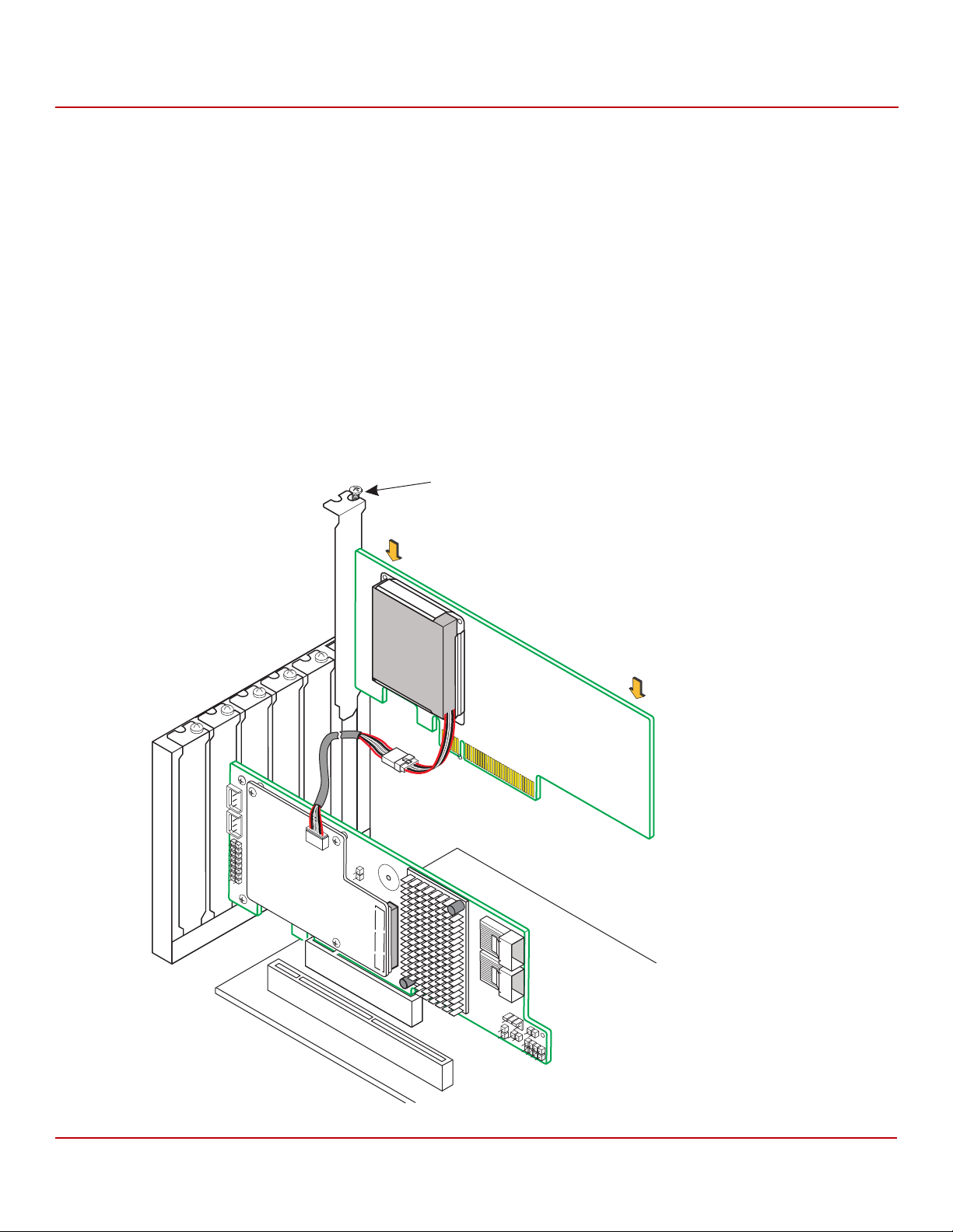
Cache Backup Products for MegaRAID SAS+SATA RAID Controllers User Guide
Bracket
Screw
Press
Here
Press
Here
3_00895-00
May 2015
Connecting a CVFM02 Module on a RAID Controller to a CVPM02 Module Mounted on a
2.9.6 Installing the Remote Mount Board in the System
Follow these steps to install the remote mount board in the computer.
1. With the power to the chassis still turned off and the power cords unplugged, make sure that the chassis is
grounded and has no AC power.
2. Insert the remote mount board in a PCIe slot on the motherboard, as shown in the following figure.
NOTE This controller is a PCIe x8 card, and it can operate in x8 or x16 slots.
Some PCIe slots, however, support only PCIe graphics cards; if a
remote mount board is installed in one of these slots, the remote
mount board will not function. Refer to the guide for your
motherboard for information about the PCIe slot.
3. Press down gently, but firmly, to seat the board correctly in the slot.
4. Secure the remote mount board to the computer chassis with the bracket screw.
Figure 64 Installing the Remote Mount Board
Chapter 2: Installing the Cache Backup Products
Remote Mount Board
Avago Technologies
- 95 -
Page 96

Cache Backup Products for MegaRAID SAS+SATA RAID Controllers User Guide
Top View
Bottom View
J2A1
Connector
J2M1
Connector
3_00917-00
May 2015
Attaching the CVFM03 Module to a MegaRAID SAS 9265CV-8i RAID Controller and
Chapter 2: Installing the Cache Backup Products
Connecting to a Remote CVPM02 Module
5. Reinstall the computer cover, and reattach the power cords.
6. Turn on the power to the computer.
Refer to the MegaRAID SAS Software User Guide for information on running the RAID configuration utility and the
MegaRAID SAS Device Driver Installation User Guide for information on installing the software drivers.
2.10 Attaching the CVFM03 Module to a MegaRAID SAS 9265CV-8i RAID Controller and Connecting to a Remote CVPM02 Module
This section describes how to attach the CVFM03 module to the MegaRAID SAS 9265CV-8i RAID controller, and then
connect the CVFM03 module to a remote CVPM02 module.
2.10.1 Top View and Bottom View of the CVFM03 Module
The following figure shows the top view and the bottom view of the CVFM03 module. The top view is the side that
you can see when the unit is installed on a RAID controller.
Figure 65 Top View and Bottom View of the CVFM03 Module
NOTE Record your controller serial number in a safe location, in case you
need to contact Avago.
Avago Technologies
- 96 -
Page 97

Cache Backup Products for MegaRAID SAS+SATA RAID Controllers User Guide
May 2015
Attaching the CVFM03 Module to a MegaRAID SAS 9265CV-8i RAID Controller and
Chapter 2: Installing the Cache Backup Products
Connecting to a Remote CVPM02 Module
2.10.2 Installing the CVFM03 Module Directly on the MegaRAID SAS 9265CV-8i RAID Controller
Follow these steps to install the CVFM03 module directly on the LSIiBB05.
1. Remove the RAID controller from the computer. For this procedure, see Section 2.10.2.1, Removing the RAID
Controller from the Computer, on page 97.
2. Attach the CVFM03 module directly to the RAID controller. For this procedure, see Section 2.10.2.2, Attaching the
CVFM03 Module Directly to the RAID Controller on page 98
CAUTION Electrostatic discharge can damage the CVFM03 module and the
MegaRAID SAS 9265CV-8i RAID controller. Make sure that you install
the CVFM03 module at an ESD-safe workstation that meets the
EIA-625 Standard. When you install the CVFM03 module, follow the
ESD-recommended practices in the latest revision of the IPC-A-610
(Acceptability of Electronic Assemblies) standard.
2.10.2.1 Removing the RAID Controller from the Computer
Follow these steps to remove the RAID controller from the computer.
1. Turn off the power, and unplug the power cords.
2. Ground yourself, and make sure that the system is grounded.
3. Remove the cover from the computer according to the instructions in the system user’s manual to allow access to
the controller.
4. Unplug all cables from the controller, remove the screw that attaches the bracket to the computer chassis, and
carefully remove the controller from the slot.
5. Place the controller on a flat, clean, static-free surface, and continue with the next procedure.
.
Avago Technologies
- 97 -
Page 98

Cache Backup Products for MegaRAID SAS+SATA RAID Controllers User Guide
3_00914-00
CacheVault
Flash Module
(CVFM03)
J5B1
May 2015
Attaching the CVFM03 Module to a MegaRAID SAS 9265CV-8i RAID Controller and
2.10.2.2 Attaching the CVFM03 Module Directly to the RAID Controller
Follow these steps to attach the CVFM03 module directly to the RAID controller.
WAR NIN G There is danger of an explosion if the battery is incorrectly replaced.
Replace the battery only with the same or equivalent type
recommended by the manufacturer. Dispose of used batteries
according to the manufacturer’s instructions.
1. Ground yourself, and make sure that the system is grounded.
2. Remove the CVFM03 module from the package.
3. Place the CVFM03 module front-side-up on a flat, clean, static-free surface.
4. Place the RAID controller on a flat, clean, static-free surface.
5. Hold the CVFM03 module so that the top side is facing upward, and align the J2M1 connector on the CVFM03
module with the J5B1 BBU connector on the RAID controller, as shown in the following figure.
Figure 66 Attaching the CVFM03 Module Directly to the RAID Controller
Chapter 2: Installing the Cache Backup Products
Connecting to a Remote CVPM02 Module
6. Carefully press the CVFM03 module onto the RAID controller so that the two connectors are firmly joined.
7. Secure the CVFM03 module to the RAID controller with the screws and the standoffs in the three screw holes.
The standoffs are threaded at both ends, and a screw goes into each end. The screw threads from the back of the
controller board into the board-to-board standoffs on the bottom of the CVFM03 module.
NOTE Center the screwdriver carefully to avoid stripping the screw heads.
Do not overtighten the screws.
Avago Technologies
- 98 -
Page 99

Cache Backup Products for MegaRAID SAS+SATA RAID Controllers User Guide
A
A
A
Clip
3_00895b-00
May 2015
Attaching the CVFM03 Module to a MegaRAID SAS 9265CV-8i RAID Controller and
2.10.3 Installing the Clip Directly on the Remote Mount Board
Follow these steps to install the clip directly on the remote mount board.
1. Place the remote mount board on a flat, clean, static-free surface.
2. Ground yourself and make sure the system is grounded.
3. Remove the clip and the remote mount board module from the package.
4. Place the clip and the remote mount board module front-side-up on a flat, clean, static-free surface.
5. Hold the clip to line up the screw holes on the clip with the screw holes on the remote mount board, as shown in
the following figure.
Figure 67 Installing the Clip Directly on the Remote Mount Board
Chapter 2: Installing the Cache Backup Products
Connecting to a Remote CVPM02 Module
6. Secure the clip to the CVPM02 module in three screw holes with the screws and the nuts.
The screws thread through the front of the clip and the remote mount board.
NOTE Center the screwdriver carefully to avoid stripping the screw heads.
Do not overtighten the screws.
Avago Technologies
- 99 -
Page 100

Cache Backup Products for MegaRAID SAS+SATA RAID Controllers User Guide
A
CacheVault
Power Module
Clip
3_01275b-00
May 2015
Attaching the CVFM03 Module to a MegaRAID SAS 9265CV-8i RAID Controller and
Chapter 2: Installing the Cache Backup Products
Connecting to a Remote CVPM02 Module
2.10.4 Attaching the CVPM02 Module to the Clip on the Remote Mount Board
Follow these steps to attach the CVPM02 module to the clip on the remote mount board.
1. Place the remote mount board on a flat, clean, static-free surface.
2. Ground yourself and make sure the system is grounded.
3. Remove the CVPM02 module from the package.
4. Press the CVPM02 module into the clip on the remote mount board until the module clicks firmly into place, as
shown in the following figure.
Figure 68 Attaching the CVPM02 Module to the Clip on the Remote Mount Board
Avago Technologies
- 100 -
 Loading...