

Page 1
6Gb/s MegaRAID® SAS RAID Controllers
41450-04D
User Guide
41450-04, Rev. D
October 2013
Page 2
6Gb/s MegaRAID SAS RAID Controllers User Guide
October 2013
Revision History
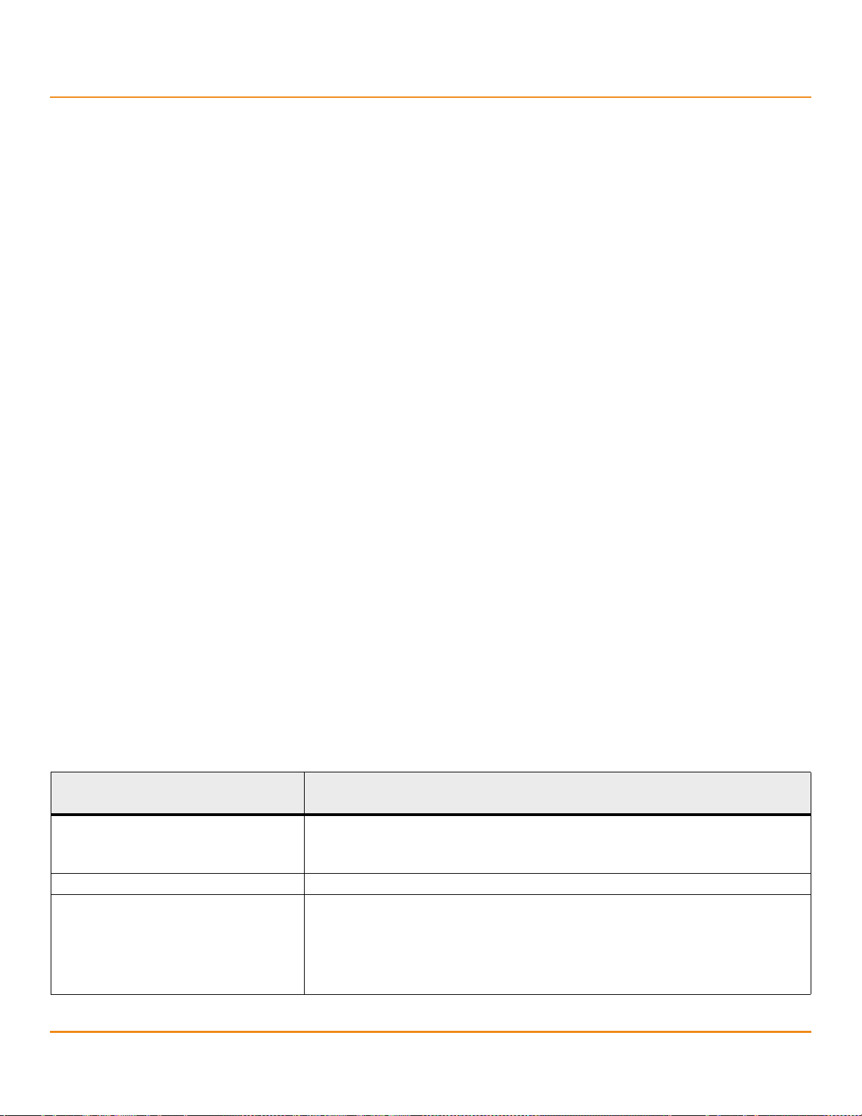
Version and Date Description of Changes
41450-04, Rev. D, October 2013 Updated the connector information for the MegaRAID® SAS 9266-4i and SAS 9266-8i controllers. Updated the
connector labels for the card layout graphics for the MegaRAID SAS 9266-8i and SAS 9271-8i controllers.
41450-04, Rev. C, August 2013 Updated the environmental conditions for the RAID controllers.
41450-04, Rev. B, February 2013 Updated the environmental conditions for the RAID controllers.
Updated this guide to the new template.
41450-04, Rev. A, August 2012 Added the MegaRAID SAS 9270-8i, SAS 9271-4i, SAS 9271-8i, SAS 9271-8iCC, SAS 9286-8e, SAS 9286CV-8e, and
SAS 9286CV-8eCC RAID controllers.
41450-03, Rev. A, April 2012 Added the MegaRAID SAS 9265CV-8i, SAS 9266-4i, SAS 9266-8i, and SAS 9285CV-8e RAID controllers.
41450-02, Rev. E, February 2011 Added the MegaRAID SAS 9260CV-4i, SAS 9260CV-8i, SAS 9265-8i, and SAS 9285-8e RAID controllers.
41450-02, Rev. D, June 2010 Added the MegaRAID SAS 9260-16i, SAS 9280-16i4e, and SAS 9280-24i4e RAID controllers.
41450-02, Rev. C, April 2010 Put this guide in the new template.
41450-02, Rev. B, November 2009 Added the MegaRAID SAS 9240-4i, SAS 9240-8i, SAS 9261-8i, and SAS 9280-4i4e RAID controllers.
41450-02, Rev. A, July 2009 Added the MegaRAID SAS 9260-4i, SAS 9260DE-8i, SAS 9280-8e, and SAS 9280DE-8e RAID controllers.
41450-01, Rev. A, June 2009 Added the MegaRAID SAS 9260-8i RAID controller.
41450-00, Rev. A, March 2009 Initial release of this document.
LSI, the LSI & Design logo, Storage.Networking.Accelerated., CacheCade, CacheVault, Fusion-MPT, MegaRAID, MegaRAID Storage Manager, and SafeStore are trademarks or registered trademarks of
LSI Corporation in the United S t ates an d/o r other cou nt ries. The Powe rP C name an d logo ar e regi stered tr adem arks of IBM C orp. an d used un der lice nse ther efro m. Al l othe r bran d and pr oduct na mes ma y
be trademarks of their respective companies.
LSI Corporation reserves the right to make changes to the product(s) or information disclosed herein at any time without notice. LSI Corporation does not assume any responsibility or liability arising o ut of
the application or use of any product or service de scribed herein, excep t as expressly agreed to i n writing by LSI Co rporation; nor does the purchase, l ease, or use of a product or ser vice from LSI Corpor ation
convey a license under any p at en t r i gh t s , co pyr ights, trademark rights, or any oth er o f the i nt el lectu al pr op er ty ri g hts of LSI Corporation or of third parties. LSI products are not intended for use in life-support
appliances, devices, or systems. Use of any LSI product in such applications without written consent of the appropriate LSI officer is prohibited.
Corporate Headquarters Website
San Jose, CA www.lsi.com
800-372-2447
Document Number: 41450-04, Rev. D
Copyright © 2013 LSI Corpora tion
All Rights Reserved
Page 3

6Gb/s MegaRAID SAS RAID Controllers User Guide
October 2013
Table of Contents
Table of Contents
Chapter 1: Overview . . . . . . . . . . . . . . . . . . . . . . . . . . . . . . . . . . . . . . . . . . . . . . . . . . . . . . . . . . . . . . . . . . . . . . . . . . . . . . . . . . . . . . . . . . . . . . . . . . . . . . . . . . . . 5
1.1 Overview . . . . . . . . . . . . . . . . . . . . . . . . . . . . . . . . . . . . . . . . . . . . . . . . . . . . . . . . . . . . . . . . . . . . . . . . . . . . . . . . . . . . . . . . . . . . . . . . . . . . . . . . . . . . . . . . . . . . . . . . . . . 5
1.1.1 MegaRAID SATA+SAS Controllers with Disk Encryption Support . . . . . . . . . . . . . . . . . . . . . . . . . . . . . . . . . . . . . . . . . . . . . . . . . . . . . . . . . . . . . . . 5
1.1.2 MegaRAID SATA+SAS Controllers with Support for Battery Backup Units and CacheVault Modules . . . . . . . . . . . . . . . . . . . . . . . . . . . . . . 6
1.1.3 SAS/SATA Standards and Communication Protocols . . . . . . . . . . . . . . . . . . . . . . . . . . . . . . . . . . . . . . . . . . . . . . . . . . . . . . . . . . . . . . . . . . . . . . . . . . . 6
1.2 General Description . . . . . . . . . . . . . . . . . . . . . . . . . . . . . . . . . . . . . . . . . . . . . . . . . . . . . . . . . . . . . . . . . . . . . . . . . . . . . . . . . . . . . . . . . . . . . . . . . . . . . . . . . . . . . . . . 7
1.3 6Gb/s MegaRAID SATA+SAS RAID Controller Detailed Descriptions . . . . . . . . . . . . . . . . . . . . . . . . . . . . . . . . . . . . . . . . . . . . . . . . . . . . . . . . . . . . . . . . . . . 7
1.3.1 MegaRAID SAS 9240 RAID Controllers . . . . . . . . . . . . . . . . . . . . . . . . . . . . . . . . . . . . . . . . . . . . . . . . . . . . . . . . . . . . . . . . . . . . . . . . . . . . . . . . . . . . . . . . . 7
1.3.2 MegaRAID SAS 9260 RAID Controllers . . . . . . . . . . . . . . . . . . . . . . . . . . . . . . . . . . . . . . . . . . . . . . . . . . . . . . . . . . . . . . . . . . . . . . . . . . . . . . . . . . . . . . . . . 7
1.3.3 MegaRAID SAS 9261 RAID Controller . . . . . . . . . . . . . . . . . . . . . . . . . . . . . . . . . . . . . . . . . . . . . . . . . . . . . . . . . . . . . . . . . . . . . . . . . . . . . . . . . . . . . . . . . . 8
1.3.4 MegaRAID SAS 9265 RAID Controllers . . . . . . . . . . . . . . . . . . . . . . . . . . . . . . . . . . . . . . . . . . . . . . . . . . . . . . . . . . . . . . . . . . . . . . . . . . . . . . . . . . . . . . . . . 8
1.3.5 MegaRAID SAS 9266 RAID Controllers . . . . . . . . . . . . . . . . . . . . . . . . . . . . . . . . . . . . . . . . . . . . . . . . . . . . . . . . . . . . . . . . . . . . . . . . . . . . . . . . . . . . . . . . . 8
1.3.6 MegaRAID SAS 9270 RAID Controller . . . . . . . . . . . . . . . . . . . . . . . . . . . . . . . . . . . . . . . . . . . . . . . . . . . . . . . . . . . . . . . . . . . . . . . . . . . . . . . . . . . . . . . . . . 8
1.3.7 MegaRAID SAS 9271 RAID Controllers . . . . . . . . . . . . . . . . . . . . . . . . . . . . . . . . . . . . . . . . . . . . . . . . . . . . . . . . . . . . . . . . . . . . . . . . . . . . . . . . . . . . . . . . . 8
1.3.8 MegaRAID SAS 9280 RAID Controllers . . . . . . . . . . . . . . . . . . . . . . . . . . . . . . . . . . . . . . . . . . . . . . . . . . . . . . . . . . . . . . . . . . . . . . . . . . . . . . . . . . . . . . . . . 9
1.3.9 MegaRAID SAS 9285 RAID Controllers . . . . . . . . . . . . . . . . . . . . . . . . . . . . . . . . . . . . . . . . . . . . . . . . . . . . . . . . . . . . . . . . . . . . . . . . . . . . . . . . . . . . . . . . . 9
1.3.10 MegaRAID SAS 9286 RAID Controllers . . . . . . . . . . . . . . . . . . . . . . . . . . . . . . . . . . . . . . . . . . . . . . . . . . . . . . . . . . . . . . . . . . . . . . . . . . . . . . . . . . . . . . . 9
1.4 Configuration Scenarios . . . . . . . . . . . . . . . . . . . . . . . . . . . . . . . . . . . . . . . . . . . . . . . . . . . . . . . . . . . . . . . . . . . . . . . . . . . . . . . . . . . . . . . . . . . . . . . . . . . . . . . . . . . . 9
1.5 Benefits of the SAS Interface . . . . . . . . . . . . . . . . . . . . . . . . . . . . . . . . . . . . . . . . . . . . . . . . . . . . . . . . . . . . . . . . . . . . . . . . . . . . . . . . . . . . . . . . . . . . . . . . . . . . . . . 11
1.5.1 PCIe Architecture . . . . . . . . . . . . . . . . . . . . . . . . . . . . . . . . . . . . . . . . . . . . . . . . . . . . . . . . . . . . . . . . . . . . . . . . . . . . . . . . . . . . . . . . . . . . . . . . . . . . . . . . . . . 11
1.5.2 Operating System Support . . . . . . . . . . . . . . . . . . . . . . . . . . . . . . . . . . . . . . . . . . . . . . . . . . . . . . . . . . . . . . . . . . . . . . . . . . . . . . . . . . . . . . . . . . . . . . . . . . 11
1.6 Summary of 6Gb/s MegaRAID SATA+SAS RAID Controller Characteristics . . . . . . . . . . . . . . . . . . . . . . . . . . . . . . . . . . . . . . . . . . . . . . . . . . . . . . . . . . . . 12
1.6.1 SAS Features . . . . . . . . . . . . . . . . . . . . . . . . . . . . . . . . . . . . . . . . . . . . . . . . . . . . . . . . . . . . . . . . . . . . . . . . . . . . . . . . . . . . . . . . . . . . . . . . . . . . . . . . . . . . . . . . 13
1.6.2 SAS Array Limitations . . . . . . . . . . . . . . . . . . . . . . . . . . . . . . . . . . . . . . . . . . . . . . . . . . . . . . . . . . . . . . . . . . . . . . . . . . . . . . . . . . . . . . . . . . . . . . . . . . . . . . . 13
1.6.3 SATA III Features . . . . . . . . . . . . . . . . . . . . . . . . . . . . . . . . . . . . . . . . . . . . . . . . . . . . . . . . . . . . . . . . . . . . . . . . . . . . . . . . . . . . . . . . . . . . . . . . . . . . . . . . . . . . 14
1.6.4 PCIe Performance . . . . . . . . . . . . . . . . . . . . . . . . . . . . . . . . . . . . . . . . . . . . . . . . . . . . . . . . . . . . . . . . . . . . . . . . . . . . . . . . . . . . . . . . . . . . . . . . . . . . . . . . . . . 14
1.6.5 Usability Features . . . . . . . . . . . . . . . . . . . . . . . . . . . . . . . . . . . . . . . . . . . . . . . . . . . . . . . . . . . . . . . . . . . . . . . . . . . . . . . . . . . . . . . . . . . . . . . . . . . . . . . . . . . 14
1.6.6 Flexibility Features . . . . . . . . . . . . . . . . . . . . . . . . . . . . . . . . . . . . . . . . . . . . . . . . . . . . . . . . . . . . . . . . . . . . . . . . . . . . . . . . . . . . . . . . . . . . . . . . . . . . . . . . . . 15
1.6.7 Drive Roaming . . . . . . . . . . . . . . . . . . . . . . . . . . . . . . . . . . . . . . . . . . . . . . . . . . . . . . . . . . . . . . . . . . . . . . . . . . . . . . . . . . . . . . . . . . . . . . . . . . . . . . . . . . . . . . 15
1.6.8 Drive Migration . . . . . . . . . . . . . . . . . . . . . . . . . . . . . . . . . . . . . . . . . . . . . . . . . . . . . . . . . . . . . . . . . . . . . . . . . . . . . . . . . . . . . . . . . . . . . . . . . . . . . . . . . . . . . 15
1.7 Hardware Specifications . . . . . . . . . . . . . . . . . . . . . . . . . . . . . . . . . . . . . . . . . . . . . . . . . . . . . . . . . . . . . . . . . . . . . . . . . . . . . . . . . . . . . . . . . . . . . . . . . . . . . . . . . . . 16
1.8 Technical Support . . . . . . . . . . . . . . . . . . . . . . . . . . . . . . . . . . . . . . . . . . . . . . . . . . . . . . . . . . . . . . . . . . . . . . . . . . . . . . . . . . . . . . . . . . . . . . . . . . . . . . . . . . . . . . . . . 19
Chapter 2: MegaRAID SAS Hardware Installation . . . . . . . . . . . . . . . . . . . . . . . . . . . . . . . . . . . . . . . . . . . . . . . . . . . . . . . . . . . . . . . . . . . . . . . . . . . . . . . . 20
2.1 Requirements . . . . . . . . . . . . . . . . . . . . . . . . . . . . . . . . . . . . . . . . . . . . . . . . . . . . . . . . . . . . . . . . . . . . . . . . . . . . . . . . . . . . . . . . . . . . . . . . . . . . . . . . . . . . . . . . . . . . . 20
2.2 Quick Installation . . . . . . . . . . . . . . . . . . . . . . . . . . . . . . . . . . . . . . . . . . . . . . . . . . . . . . . . . . . . . . . . . . . . . . . . . . . . . . . . . . . . . . . . . . . . . . . . . . . . . . . . . . . . . . . . . . 20
2.3 Detailed Installation . . . . . . . . . . . . . . . . . . . . . . . . . . . . . . . . . . . . . . . . . . . . . . . . . . . . . . . . . . . . . . . . . . . . . . . . . . . . . . . . . . . . . . . . . . . . . . . . . . . . . . . . . . . . . . . 21
2.4 After Installing the RAID Controller . . . . . . . . . . . . . . . . . . . . . . . . . . . . . . . . . . . . . . . . . . . . . . . . . . . . . . . . . . . . . . . . . . . . . . . . . . . . . . . . . . . . . . . . . . . . . . . . . 23
2.5 SAS Device Cables and Connectors . . . . . . . . . . . . . . . . . . . . . . . . . . . . . . . . . . . . . . . . . . . . . . . . . . . . . . . . . . . . . . . . . . . . . . . . . . . . . . . . . . . . . . . . . . . . . . . . . 23
2.5.1 Connecting a SAS RAID Controller with Internal Connectors to the Drives . . . . . . . . . . . . . . . . . . . . . . . . . . . . . . . . . . . . . . . . . . . . . . . . . . . . . 25
2.5.2 Connecting a RAID Controller with External Connectors to a Drive Enclosure . . . . . . . . . . . . . . . . . . . . . . . . . . . . . . . . . . . . . . . . . . . . . . . . . . 26
Chapter 3: MegaRAID SAS RAID Controller Characteristics . . . . . . . . . . . . . . . . . . . . . . . . . . . . . . . . . . . . . . . . . . . . . . . . . . . . . . . . . . . . . . . . . . . . . . . 28
3.1 6Gb/s MegaRAID SAS RAID Controller Family . . . . . . . . . . . . . . . . . . . . . . . . . . . . . . . . . . . . . . . . . . . . . . . . . . . . . . . . . . . . . . . . . . . . . . . . . . . . . . . . . . . . . . . 28
3.1.1 MegaRAID SAS 9240 RAID Controllers . . . . . . . . . . . . . . . . . . . . . . . . . . . . . . . . . . . . . . . . . . . . . . . . . . . . . . . . . . . . . . . . . . . . . . . . . . . . . . . . . . . . . . . . 28
3.1.2 MegaRAID SAS 9260 RAID Controllers . . . . . . . . . . . . . . . . . . . . . . . . . . . . . . . . . . . . . . . . . . . . . . . . . . . . . . . . . . . . . . . . . . . . . . . . . . . . . . . . . . . . . . . . 29
3.1.3 MegaRAID SAS 9261 RAID Controller . . . . . . . . . . . . . . . . . . . . . . . . . . . . . . . . . . . . . . . . . . . . . . . . . . . . . . . . . . . . . . . . . . . . . . . . . . . . . . . . . . . . . . . . . 38
3.1.4 MegaRAID SAS 9265 RAID Controllers . . . . . . . . . . . . . . . . . . . . . . . . . . . . . . . . . . . . . . . . . . . . . . . . . . . . . . . . . . . . . . . . . . . . . . . . . . . . . . . . . . . . . . . . 39
3.1.5 MegaRAID SAS 9266 RAID Controllers . . . . . . . . . . . . . . . . . . . . . . . . . . . . . . . . . . . . . . . . . . . . . . . . . . . . . . . . . . . . . . . . . . . . . . . . . . . . . . . . . . . . . . . . 44
3.1.6 MegaRAID SAS 9270 RAID Controller . . . . . . . . . . . . . . . . . . . . . . . . . . . . . . . . . . . . . . . . . . . . . . . . . . . . . . . . . . . . . . . . . . . . . . . . . . . . . . . . . . . . . . . . . 47
3.1.7 MegaRAID SAS 9271 RAID Controllers . . . . . . . . . . . . . . . . . . . . . . . . . . . . . . . . . . . . . . . . . . . . . . . . . . . . . . . . . . . . . . . . . . . . . . . . . . . . . . . . . . . . . . . . 49
LSI Corporation
- 3 -
Page 4

6Gb/s MegaRAID SAS RAID Controllers User Guide
October 2013
Table of Contents
3.1.8 MegaRAID SAS 9280 RAID Controllers . . . . . . . . . . . . . . . . . . . . . . . . . . . . . . . . . . . . . . . . . . . . . . . . . . . . . . . . . . . . . . . . . . . . . . . . . . . . . . . . . . . . . . . . 52
3.1.9 MegaRAID SAS 9285 RAID Controllers . . . . . . . . . . . . . . . . . . . . . . . . . . . . . . . . . . . . . . . . . . . . . . . . . . . . . . . . . . . . . . . . . . . . . . . . . . . . . . . . . . . . . . . . 58
3.1.10 MegaRAID SAS 9286 RAID Controllers . . . . . . . . . . . . . . . . . . . . . . . . . . . . . . . . . . . . . . . . . . . . . . . . . . . . . . . . . . . . . . . . . . . . . . . . . . . . . . . . . . . . . . 62
3.2 MegaRAID SAS 6Gb/s RAID Controller Characteristics . . . . . . . . . . . . . . . . . . . . . . . . . . . . . . . . . . . . . . . . . . . . . . . . . . . . . . . . . . . . . . . . . . . . . . . . . . . . . . . 67
3.3 Technical Specifications . . . . . . . . . . . . . . . . . . . . . . . . . . . . . . . . . . . . . . . . . . . . . . . . . . . . . . . . . . . . . . . . . . . . . . . . . . . . . . . . . . . . . . . . . . . . . . . . . . . . . . . . . . . 67
3.3.1 RAID Controller Specifications . . . . . . . . . . . . . . . . . . . . . . . . . . . . . . . . . . . . . . . . . . . . . . . . . . . . . . . . . . . . . . . . . . . . . . . . . . . . . . . . . . . . . . . . . . . . . . . 69
3.3.2 Array Performance Features . . . . . . . . . . . . . . . . . . . . . . . . . . . . . . . . . . . . . . . . . . . . . . . . . . . . . . . . . . . . . . . . . . . . . . . . . . . . . . . . . . . . . . . . . . . . . . . . . 72
3.3.3 Fault Tolerance . . . . . . . . . . . . . . . . . . . . . . . . . . . . . . . . . . . . . . . . . . . . . . . . . . . . . . . . . . . . . . . . . . . . . . . . . . . . . . . . . . . . . . . . . . . . . . . . . . . . . . . . . . . . . 72
3.3.4 Electrical Characteristics and Environmental Conditions . . . . . . . . . . . . . . . . . . . . . . . . . . . . . . . . . . . . . . . . . . . . . . . . . . . . . . . . . . . . . . . . . . . . . . 73
3.3.5 Safety Characteristics . . . . . . . . . . . . . . . . . . . . . . . . . . . . . . . . . . . . . . . . . . . . . . . . . . . . . . . . . . . . . . . . . . . . . . . . . . . . . . . . . . . . . . . . . . . . . . . . . . . . . . . . 88
Glossary . . . . . . . . . . . . . . . . . . . . . . . . . . . . . . . . . . . . . . . . . . . . . . . . . . . . . . . . . . . . . . . . . . . . . . . . . . . . . . . . . . . . . . . . . . . . . . . . . . . . . . . . . . . . . . . . . . . . . . 89
LSI Corporation
- 4 -
Page 5

6Gb/s MegaRAID SAS RAID Controllers User Guide
October 2013
Chapter 1: Overview
This document is the primary reference and user’s guide for the LSI® MegaRAID® SATA+SAS RAID controllers based on
the 6Gb/s SAS/SATA RAID on a chip devices. This document contains complete installation instructions for these RAID
controllers and includes specifications for them.
1.1 Overview
The MegaRAID 6Gb/s SAS RAID controllers are high-performance intelligent PCI Express® (PCIe®)-to-SATA+SAS
controllers with RAID control capability. The MegaRAID 6Gb/s SAS RAID controllers provide reliability,
high-performance, and fault-tolerant drive subsystem management. They are an ideal RAID solution for the internal
storage of workgroup, departmental, and enterprise systems. The MegaRAID 6Gb/s SAS RAID controllers offer a
cost-effective way to implement RAID in a server.
SAS technology brings a wealth of options and flexibility with the use of SAS and SATA devices within the same
storage infrastructure. However, SAS devices and SATA devices bring individual characteristics that make each one a
more suitable choice depending on your storage needs. MegaRAID controllers offer the flexibility to combine these
two similar technologies on the same controller and within the same enclosure.
Overview
Overview
NOTE You can have both SAS drives and SATA drives within the same virtual
drive, too; however, the practice is strongly discouraged.
LSI offers a family of MegaRAID SATA+SAS RAID controllers that address the needs for both internal and external
solutions. The MegaRAID 6Gb/s SAS RAID controllers are based on the LSI first-to-market SAS IC technology and
proven MegaRAID technology. As second-generation PCIe RAID controllers, these controllers address the growing
demand for increased data throughput and scalability requirements across midrange and enterprise-class server
platforms. These controllers provide these features:
6Gb/s Serial Attached SCSI (SAS) performance
6Gb/s SATA III performance
Eight-lane, 5 GT/s PCIe host interface
1.1.1 MegaRAID SATA+SAS Controllers with Disk Encryption Support
The MegaRAID SAS 9260DE-8i RAID controller and the MegaRAID SAS 9280DE-8i RAID controller offer data security
using disk encryption. This feature offers the ability to encrypt data on drives and use disk-based key management to
provide data security. This solution provides data protection in the event of theft or loss of physical drives. With
self-encrypting drives, if you remove a drive from its storage system or the server in which it is housed, the data
on that drive is encrypted and is useless to anyone who attempts to access without the appropriate
security authorization.
For more information about self-encrypting drives, refer to the MegaRAID SAS Software User Guide on the MegaRAID
Universal Software Suite CD.
LSI Corporation
- 5 -
Page 6

6Gb/s MegaRAID SAS RAID Controllers User Guide
October 2013
Overview
Overview
1.1.2 MegaRAID SATA+SAS Controllers with Support for Battery Backup Units and CacheVault Modules
Some MegaRAID SATA+SAS RAID controllers can use optional cache products, which include a battery backup
unit (iBBU) or a CacheVault® Flash Module (CVFM), to protect cached data even during the most catastrophic
system failures.
The following MegaRAID SATA+SAS RAID controllers can use a CacheVault Flash Module (CVFM) with a CacheVault
Power Module (CVPM) to protect cached data in case of a power failure or outage:
MegaRAID SAS 9260CV-4i
MegaRAID SAS 9260CV-8i
MegaRAID SAS 9265CV-8i
MegaRAID SAS 9266-4i
MegaRAID SAS 9266-8i
MegaRAID SAS 9271-4i
MegaRAID SAS 9271-8i
MegaRAID SAS 9271-8iCC
MegaRAID SAS 9285CV-8e
MegaRAID SAS 9286CV-8e
MegaRAID SAS 9286CV-8eCC
Refer to the Cache Backup Products for MegaRAID SAS RAID Controllers User Guide, the MegaRAID CacheVault Power
Module 02 Quick Installation Guide, the battery backup unit quick installation guides, and the RAID controller quick
installation guides on the MegaRAID Universal Software Suite CD for more information about the battery backup units
and the CacheVault modules.
1.1.3 SAS/SATA Standards and Communication Protocols
MegaRAID SATA+SAS controllers support the ANSI® Serial Attached SCSI standard, version 2.0. In addition, the controller
supports the SATA III protocol defined by the Serial ATA specification, version 3.0. Supporting both the SAS interface
and the SATA interface, the SAS controller is a versatile controller that provides the backbone of both server and
high-end workstation environments.
Each port on your MegaRAID SAS RAID controller supports SAS devices, SATA devices, or both, by using the
following protocols:
SAS Serial SCSI Protocol (SSP), which enables communication with other SAS devices
SATA, which enables communication with other SATA devices
Serial Management Protocol (SMP), which communicates topology management information directly with an
attached SAS expander device
Serial Tunneling Protocol (STP), which enables communication with SATA devices through an attached expander
LSI Corporation
- 6 -
Page 7

6Gb/s MegaRAID SAS RAID Controllers User Guide
October 2013
1.2 General Description
The MegaRAID 6Gb/s SAS RAID controllers bring 6Gb/s Serial Attached SCSI and 6Gb/s SATA III performance to host
adapter, workstation, and server designs. The controllers support internal storage devices and external storage
devices, which allow you to use a system that supports enterprise-class SAS drives and desktop-class SATA III drives.
Each MegaRAID 6Gb/s SAS RAID controller can connect to drives directly and can use expanders to connect to
additional drives. Simplified cabling between devices is an additional benefit.
These MegaRAID SATA+SAS RAID controllers are based on the following chips and devices:
LSISAS2008 PCIe-SAS/SATA I/O Processor chip
LSISAS2108 RAID On-a-Chip (ROC) device
LSISAS2208 RAID On-a-Chip (ROC) device
These devices are compliant with the Fusion-MPT™ architecture and provides a PCIe x8 interface. Each port on the
MegaRAID SAS controllers supports SAS devices, SATA devices, or both, using SSP, SMP, STP, and SATA. The SSP
protocol enables the MegaRAID SAS controllers to communicate with other SAS devices. The SATA protocol enables
the MegaRAID SAS controllers to communicate with SATA devices.
NOTE All of these RAID controllers provide an x8 PCIe 2.0 or
x8 PCIe 3.0 interface.
General Description
Overview
1.3 6Gb/s MegaRAID SATA+SAS RAID Controller Detailed Descriptions
The 6Gb/s MegaRAID SATA+SAS RAID controllers are described in detail in the following subsections.
1.3.1 MegaRAID SAS 9240 RAID Controllers
The MegaRAID SAS 9240-4i PCIe 2.0 Low-Profile Serial-Attached SCSI/SATA Disk Array Controller is a PCIe 2.0,
half-size, full-height RAID controller based on the LSISAS2008 PCIe-SAS/SATA I/O Processor chip. The MegaRAID
SAS 9240-4i controller controls four internal 6-Gb/s SAS/SATA ports through one SFF-8087 x4 internal mini
SAS connector.
The MegaRAID SAS 9240-8i PCIe 2.0 Low-Profile Serial-Attached SCSI/SATA Disk Array Controller is a PCIe 2.0,
half-size, full-height RAID controller based on the LSISAS2008 PCIe-SAS/SATA I/O Processor chip. The MegaRAID
SAS 9240-8i controller controls eight internal 6-Gb/s SAS/SATA ports through two SFF-8087 x4 internal mini
SAS connectors.
1.3.2 MegaRAID SAS 9260 RAID Controllers
The 6Gb/s MegaRAID SAS 9260-4i PCIe 2.0 Low-Profile Serial-Attached SCSI/SATA Disk Array Controller
controls four internal SAS/SATA ports through one SFF-8087 x4 internal mini SAS connector.
The 6Gb/s MegaRAID SAS 9260-8i PCIe 2.0 Low-Profile Serial-Attached SCSI/SATA Disk Array Controller
controls eight internal SAS/SATA ports through two SFF-8087 x4 internal mini SAS connectors.
The 6Gb/s MegaRAID SAS 9260-16i PCIe 2.0 Standard-Height Serial-Attached SCSI/SATA Disk Array Controller
controls 16 internal SAS/SATA ports through four SFF-8087 x4 internal mini SAS connectors.
The 6Gb/s MegaRAID SAS 9260CV-4i PCIe 2.0 Low-Profile Serial-Attached SCSI/SATA Disk Array Controller
controls four internal SAS/SATA ports through one SFF-8087 x4 internal mini SAS connector, and it has an
onboard CacheVault Flash Module 01 (CVFM01) that connects to a remote CacheVault Power Module 01.
LSI Corporation
- 7 -
Page 8

6Gb/s MegaRAID SAS RAID Controllers User Guide
October 2013
The 6Gb/s MegaRAID SAS 9260CV-8i PCIe 2.0 Low-Profile Serial-Attached SCSI/SATA Disk Array Controller
controls eight internal SAS/SATA ports through two SFF-8087 x4 internal mini SAS connectors, and it has an
onboard CacheVault Flash Module 01 (CVFM01) that connects to a remote CacheVault Power Module 01.
The 6Gb/s MegaRAID SAS 9260DE-8i PCIe 2.0 Low-Profile Serial-Attached SCSI/SATA Disk Array Controller
controls eight internal SAS/SATA ports through two SFF-8087 x4 internal mini SAS connectors and offers data
security using disk encryption.
1.3.3 MegaRAID SAS 9261 RAID Controller
The 6Gb/s MegaRAID SAS 9261-8i PCIe 2.0 Low-Profile Serial-Attached SCSI/SATA Disk Array Controller controls eight
internal SAS/SATA ports through two SFF-8087 mini-SAS 4i internal connectors.
1.3.4 MegaRAID SAS 9265 RAID Controllers
The 6Gb/s MegaRAID SAS 9265-8i PCIe 2.0 Low-Profile Serial-Attached SCSI/SATA Disk Array Controller
controls eight internal SAS/SATA ports through two SFF-8087 x4 mini internal SAS connectors.
The 6Gb/s MegaRAID SAS 9265CV-8i PCIe 2.0 Serial-Attached SCSI/SATA Disk Array Controller controls eight
internal SAS+SATA ports through two SFF-8087 mini-SAS 4i internal connectors, and it has an onboard
CacheVault Flash Module 03 (CVFM03) that connects to a remote CacheVault Power Module 02 (CVPM02).
6Gb/s MegaRAID SATA+SAS RAID Controller Detailed Descriptions
Overview
1.3.5 MegaRAID SAS 9266 RAID Controllers
The 6Gb/s MegaRAID SAS 9266-4i PCIe 2.0 Low-Profile Serial-Attached SCSI/SATA Disk Array Controller controls
four internal SAS+SATA ports through one SFF-8087 mini SAS 4i internal connector.
The 6Gb/s MegaRAID SAS 9266-8i PCIe 2.0 Low-Profile Serial-Attached SCSI/SATA Disk Array Controller controls
eight internal SAS+SATA ports through two SFF-8087 mini SAS 4i internal connectors, and it has an on-board
CacheVault Flash Module 02 (CVFM02) that connects to a remote CacheVault Power Module 02 (CVPM02).
1.3.6 MegaRAID SAS 9270 RAID Controller
The 6Gb/s MegaRAID SAS 9270-8i PCIe 3.0 Low-Profile Serial-Attached SCSI/SATA Disk Array Controller controls eight
internal SAS/SATA ports through two SFF-8087 mini-SAS 4i internal connectors.
1.3.7 MegaRAID SAS 9271 RAID Controllers
The 6Gb/s MegaRAID SAS 9271-4i PCIe 3.0 Low-Profile Serial-Attached SCSI/SATA Disk Array Controller controls four
internal SAS/SATA ports through one SFF-8087 mini-SAS 4i internal connector.
The 6Gb/s MegaRAID SAS 9271-8i PCIe 3.0 Low-Profile Serial-Attached SCSI/SATA Disk Array Controller controls eight
internal SAS/SATA ports through two SFF-8087 mini-SAS 4i internal connectors.
The 6Gb/s MegaRAID SAS 9271-8iCC PCIe 3.0 Low-Profile Serial-Attached SCSI/SATA Disk Array Controller controls
eight internal SAS/SATA ports through two SFF-8087 mini-SAS 4i internal connectors. This RAID controller supports
CacheCade® Pro 2.0 and Fast Path software enabled out of the box, which optimize application performance in
direct-attached storage environments configured with solid-state drives (SSDs).
LSI Corporation
- 8 -
Page 9

6Gb/s MegaRAID SAS RAID Controllers User Guide
October 2013
1.3.8 MegaRAID SAS 9280 RAID Controllers
The 6Gb/s MegaRAID SAS 9280-4i4e PCIe 2.0 Low-Profile Serial-Attached SCSI/SATA Disk Array Controller
controls four internal SAS/SATA ports through one SFF-8087 x4 internal mini SAS connector and four external
SAS/SATA ports through one SFF-8088 x4 external mini SAS connector.
The 6Gb/s MegaRAID SAS 9280-8e PCIe 2.0 Low-Profile Serial-Attached SCSI/SATA Disk Array Controller
controls eight external SAS/SATA ports through two SFF-8088 x4 external mini SAS connectors.
The 6Gb/s MegaRAID SAS 9280DE-8e PCIe 2.0 Low-Profile Serial-Attached SCSI/SATA Disk Array Controller
controls eight external SAS/SATA ports through two SFF-8088 x4 external mini SAS connectors and offers data
security using disk encryption.
The 6Gb/s MegaRAID SAS 9280-16i4e PCIe 2.0 Standard-Height Serial-Attached SCSI/SATA Disk Array Controller
controls 16 internal SAS/SATA ports through four SFF-8087 x4 internal mini SAS connectors and four external
SAS/SATA ports through one SFF-8088 x4 external mini SAS connector.
The 6Gb/s MegaRAID SAS 9280-24i4e PCIe 2.0 Standard-Height Serial-Attached SCSI/SATA Disk Array Controller
controls 24 internal SAS/SATA ports through six SFF-8087 x4 internal mini SAS connectors and four external
SAS/SATA ports through one SFF-8088 x4 external mini SAS connector.
1.3.9 MegaRAID SAS 9285 RAID Controllers
Configuration Scenarios
Overview
The 6Gb/s MegaRAID SAS 9285-8e PCIe 2.0 Low-Profile Serial-Attached SCSI/SATA Disk Array Controller
controls eight external SAS/SATA ports through two SFF-8088 x4 external mini SAS connectors.
The 6Gb/s MegaRAID SAS 9285CV-8e PCIe 2.0 Low-Profile Serial-Attached SCSI/SATA Disk Array Controller
controls eight external SAS/SATA ports through two SFF-8088 x4 external mini SAS connectors, and it has
an onboard CacheVault Flash Module 03 (CVFM03) that connects to a remote CacheVault Power
Module 02 (CVPM02).
1.3.10 MegaRAID SAS 9286 RAID Controllers
The 6Gb/s MegaRAID SAS 9286-8e PCIe 3.0 Low-Profile Serial-Attached SCSI/SATA Disk Array Controller
controls eight external SAS/SATA ports through two SFF-8088 x4 external mini SAS connectors.
The 6Gb/s MegaRAID SAS 9286CV-8e PCIe 3.0 Low-Profile Serial-Attached SCSI/SATA Disk Array Controller
controls eight internal SAS/SATA ports through two SFF-8088 x4 mini external SAS connectors. This RAID
controller supports the CVFM03 module, which connects to a remote CacheVault Power Module 02.
The 6Gb/s MegaRAID SAS 9286CV-8eCC PCIe 3.0 Low-Profile Serial-Attached SCSI/SATA Disk Array Controller
controls eight internal SAS/SATA ports through two SFF-8088 x4 mini external SAS connectors. This RAID
controller supports the CVFM03 module, which connects to a remote CacheVault Power Module 02. In addition,
this controller supports CacheCade Pro 2.0 and Fast Path software enabled out of the box, which optimize
application performance in direct-attached storage environments configured with solid-state drives (SSDs).
1.4 Configuration Scenarios
You can use the MegaRAID SAS RAID controllers in three main scenarios:
Low-end, internal SATA configuration: In this configuration, use the RAID controller as a high-end SATA, SATA II,
or SATA III compatible controller that connects up to eight drives either directly or through a port expander. This
configuration is mostly for low-end or entry servers. An out-of-band I
2
C bus provides enclosure management.
Side bands of both types of internal SAS connectors support the SFF-8485 (SGPIO) interface.
Midrange internal SAS configuration: This configuration is like an internal SATA configuration, but with
high-end SAS drives. This configuration is more suitable for low-range to midrange servers.
LSI Corporation
- 9 -
Page 10
6Gb/s MegaRAID SAS RAID Controllers User Guide
Flash ROM/
SAS
PCIe
RAID Controller
SAS/SATA III Device
32-Bit Memory
Address/Data
Bus
PSBRAM/
I2C
SAS/SATA III Device
SAS/SATA III Device
SAS/SATA III Device
PCIe Interface
NVSRAM
I
2
C
Interface
LSISASx12
Flash ROM/
NVSRAM/
SRAM
I
2
C/UART
LSISASx12
PCIe Interface
8
SRAM
SRAMSDRAM
Peripheral
Bus
72-bit DDR/DDR2
with ECC
Interface
LSISAS2108
PCIe to SAS ROC
SAS
RAID Controller
Expander
Expander
October 2013
High-end external SAS/SATA configuration: This configuration is for external connectivity using SATA drives,
SATA II drives, SATA III drives, SAS drives, or combinations of SATA and SAS drives. External enclosure management
is supported through in-band, SCSI-enclosed storage. The configuration must support STP and SMP.
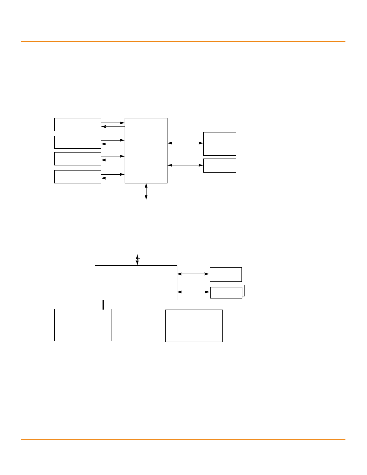
The following figure shows a direct-connect configuration. The Inter-IC (I
The external memory bus provides a 32-bit memory bus, parity checking, and chip select signals for pipelined
synchronous burst static random access memory (PSBRAM), nonvolatile static random access memory (NVSRAM), and
Flash ROM.
Figure 1 Example of an LSI SAS Direct-Connect Application
Configuration Scenarios
2
C) interface communicates with peripherals.
Overview
The following figure shows an example of a SAS RAID controller configured with an LSISASx12 expander that is
connected to SAS drives, SATA III drives, or both.
Figure 2 Example of an LSI SAS RAID Controller Configured with an LSISASx12 Expander
LSI Corporation
- 10 -
Page 11

6Gb/s MegaRAID SAS RAID Controllers User Guide
October 2013
1.5 Benefits of the SAS Interface
SAS is a serial, point-to-point, enterprise-level device interface that leverages the proven SCSI protocol set. SAS is a
convergence of the advantages of SATA, SCSI, and Fibre Channel, and it is the future mainstay of the enterprise and
high-end workstation storage markets. SAS offers a higher bandwidth per pin than parallel SCSI, and it improves
signal and data integrity.
The SAS interface uses the proven SCSI command set to ensure reliable data transfers, while providing the
connectivity and flexibility of point-to-point serial data transfers. The serial transmission of SCSI commands eliminates
clock-skew challenges. The SAS interface provides improved performance, simplified cabling, smaller connectors,
lower pin count, and lower power requirements when compared to parallel SCSI.
SAS controllers leverage a common electrical and physical connection interface that is compatible with Serial ATA
technology. The SAS protocols and the SATA III protocols use a thin, 7-wire connector instead of the 68-wire SCSI cable
or 26-wire ATA cable. The SAS/SATA III connector and cable are easier to manipulate, allow connections to smaller
devices, and do not inhibit airflow. The point-to-point SATA III architecture eliminates inherent difficulties created by
the legacy ATA master-slave architecture, while maintaining compatibility with existing ATA firmware.
1.5.1 PCIe Architecture
PCIe is a local bus system designed to increase data transfers without slowing down the central processing unit (CPU).
You can install MegaRAID PCIe RAID controllers in PCIe computer systems with a standard bracket type. With these
controllers in your system, you can connect SAS devices and SATA III devices over the bus.
Benefits of the SAS Interface
Overview
NOTE This controller is a PCIe x8 card, and it can operate in x8 or x16 slots.
Some PCIe slots, however, support only PCIe graphics cards; if the
remote mount board is installed in one of these slots, the controller
will not function. Refer to the guide for your motherboard for
information about the PCIe slot.
PCIe goes beyond the PCI specification in that it is intended as a unifying I/O architecture for various systems:
desktops, workstations, mobile devices, servers, communications, and embedded devices.
1.5.2 Operating System Support
The MegaRAID 6Gb/s SAS RAID controllers support the following operating systems:
Windows® 2000, Windows XP, Windows XP x64, Windows Server® 2003 (x86), Windows Server 2003 (x64),
Windows Vista®, Windows Server 2008, and Window Server 2012
Red Hat® Linux®
SuSE® SLES
Novell® NetWare®
SCO® OpenServer®
SCO UnixWare®
Solaris®
FreeBSD®
VMware®
Refer to the MegaRAID SAS Device Driver Installation User Guide for more information about the drivers. To download
the latest operating system drivers, go to: http://www.lsi.com/cm/DownloadSearch.do.
The MegaRAID 6Gb/s SAS RAID controllers use Fusion-MPT architecture for all major operating systems, thinner
drivers, and better performance.
LSI Corporation
- 11 -
Page 12

6Gb/s MegaRAID SAS RAID Controllers User Guide
October 2013
Summary of 6Gb/s MegaRAID SATA+SAS RAID Controller Characteristics
1.6 Summary of 6Gb/s MegaRAID SATA+SAS RAID Controller Characteristics
This section summarizes the features and benefits offered by the MegaRAID 6Gb/s SAS RAID controllers. It contains
information on SAS features, SATA features, PCI performance, integration, usability, and flexibility.
The MegaRAID 6Gb/s SAS RAID controllers have the following features:
PCIe x8 lane width (with support for x16 connections)
PCIe performance up to 5GT/s (4Gb/s) per lane
Support for a 512-MB DDR2 800-MHz onboard SDRAM for LSISAS2108-based controllers
Support for a 1-GB DDR3 1333-MT/s onboard SDRAM for LSISAS2208-based controllers
One internal connector for the MegaRAID SAS 9240-4i, SAS 9260-4i, SAS 9260CV-4i, SAS 9266-4i, SAS 9271-4i, and
SAS 9280-4i4e RAID controllers
Two internal connectors for the MegaRAID SAS 9240-8i, SAS 9260-8i, SAS 9260CV-8i, SAS 9260DE-8i, SAS 9261-8i,
SAS 9265CV-8i, SAS 9265-8i, SAS 9266-8i, SAS 9270-8i, and SAS 9271-8i RAID controllers
Four internal connectors for the MegaRAID SAS 9260-16i and SAS 9280-16i4e RAID controllers
Six internal connectors for the MegaRAID SAS 9280-24i4e RAID controller
One external connector for the MegaRAID SAS 9280-4i4e, SAS 9280-16i4e, and SAS 9280-24i4e RAID controllers
Two external connectors for the MegaRAID SAS 9280-8e, SAS 9280DE-8e, SAS 9285-8e, SAS 9285CV-8e, SAS
9285DE-8e, SAS 9286-8e, SAS 9286CV-8e, SAS 9286CV-8eCC RAID controllers
Support for RAID levels 0, 1, 5, 6, 10, 50, and 60
Advanced array configuration and management utilities
Support for global hot spares and dedicated hot spares
Support for user-defined strip sizes: 8, 16, 32, 64, 128, 256, 512, or 1024 KB
Overview
NOTE RAID 0, 1, and 10 configurations for MegaRAID SAS 9240 RAID
controllers are limited to 16 drives and 64K stripe size. To exceed these
limitations, you can plug in a new MegaRAID SAS 9260 RAID controller
or a new MegaRAID SAS 9280 RAID controller. The MegaRAID Storage
Manager™ utility recognizes and imports the existing array with no
reconfiguration required.
Advanced array configuration and management utilities offer these capabilities:
— Online capacity expansion to add space to an existing drive or a new drive
— Online RAID level migration
— Drive migration
— Drive roaming
— No reboot necessary after expansion
— Load balancing
— Media scan
User-specified rebuild rate (specifying the percentage of system resources to use from 0 percent to 100 percent)
Nonvolatile random access memory (NVRAM) of 32 KB for storing RAID system configuration information; the
MegaRAID SAS firmware is stored in flash ROM for easy upgrade.
LSI Corporation
- 12 -
Page 13
6Gb/s MegaRAID SAS RAID Controllers User Guide
October 2013
1.6.1 SAS Features
The MegaRAID 6Gb/s SAS RAID controllers support the following SAS features:
Four fully independent PHYs or eight fully independent PHYs, depending on the controller.
Support of 6Gb/s and 3Gb/s SAS data transfers per PHY.
Support of SMP to communicate topology-management information.
Support of SSP to enable communication with other SAS devices.
Support of STP to enable communication with SATA devices through an attached expander.
Serial, point-to-point, enterprise-level storage interface.
Simplified cabling between devices.
Scalable interface that supports up to 240 devices through the use of expanders
NOTE The number of devices varies depending on the controller. Check the
Support of wide ports that consist of two, three, or four PHYs within a single quad port.
Support of narrow ports consisting of a single PHY.
Data transfer using SCSI information units.
Summary of 6Gb/s MegaRAID SATA+SAS RAID Controller Characteristics
LSI website (http://www.lsi.com) for details about your product.
Overview
1.6.2 SAS Array Limitations
This section describes the array limitations of the MegaRAID 6Gb/s SAS RAID controllers. These limitations include the
number of drives supported per controller, the maximum number of drives per controller, and the maximum number
of virtual drives allowed per controller.
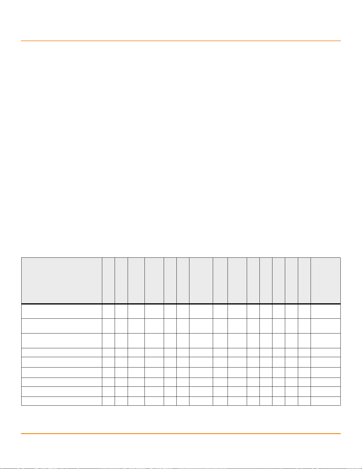
The following table lists the array limitations for the MegaRAID 6Gb/s SAS RAID controllers.
Table 1 6Gb/s MegaRAID SATA+SAS RAID Controllers Array Limitations
Specification
SAS 9240-4i
SAS 9240-8i
SAS 9260-4i
SAS 9260-8i
SAS 9260CV-4i
SAS 9260CV-8i
Maximum virtual drives per
16 16 64 64 64 64 64 64 64 64 64 64 64 64 64
controller
Maximum drive groups per
16 16 128 128 128 128 128 128 128 128 128 128 128 128 128
controller
Maximum virtual drives per drive
16 16 16 16 16 16 16 16 16 16 16 16 16 16 16
group
Maximum drives per drive group 1616 32 32 3232 32 32 32 3232323232 32
a
Maximum drives per controller
Maximum hot spares per controller
16
16a16
a
128 128 128 128 128 128 128 240 240 240 240 240 240
16
a
128 128 128 128 128 128 128 240 240 240 240 240 240
Maximum spans per virtual drive 88 8 8 88 8 8 8 88888 8
Maximum enclosures per port
b
2 2 2 2 10 2 2 2 2 10 10 2 10 10 10
Number of port connectors 12 1 2 42 2 1 2 22257 2
SAS 9260-16i
SAS 9261-8i
SAS 9265-8i
SAS 9265CV-8i
SAS 9265-8i
SAS 9266-4i
SAS 9271-4i
SAS 9266-8i
SAS 9271-8i
SAS 9280 4i4e
SAS 9280-8e
SAS 9280DE-8e
SAS 9280-16i4e
SAS 9280-24i4e
SAS 9285-8e
SAS 9285CV-8e
SAS 9286-8e
SAS 9286CV-8e
a. These controllers can support up to 64 devices, but only 16 can be used in a RAID configuration.
b. The number assumes one storage enclosure processor (SEP) per enclosure.
LSI Corporation
- 13 -
Page 14

6Gb/s MegaRAID SAS RAID Controllers User Guide
October 2013
The maximum numbers in the previous table depend on how many physical devices you have connected to the RAID
controller. For example, the maximum number of drive groups is equal to the number of drives that are supported by
the controller. Thus, for the MegaRAID SAS 9240-4i RAID controller, the maximum number of drive groups per
controller is 16, which is based on the maximum number of physical devices that you can connect. In addition, the
maximum number of hot spares per controller is equal to the maximum number of drives per controller.
Although you can have up to 16 virtual drives per drive group, and up to 128 drive groups on most of the controllers,
a limit of 64 virtual drives exists on those controllers.
These RAID controllers support 64-bit logical block addressing (LBA), which makes it possible to connect a large
number of drives to the RAID controller, directly and through expanders. However, the actual number of drives that
you can attach depends on the limits listed in this table rather than by actual RAID volume capacity.
1.6.3 SATA III Features
The following list describes the SATA III features of the RAID controllers:
They support SATA III data transfers of 3Gb/s (for LSISAS2108-based controllers) and 6Gb/s (for
LSISAS2208-based controllers).
They support STP data transfers of 3Gb/s.
They provide a serial, point-to-point storage interface.
They simplify cabling between devices.
They eliminate the master-slave construction used in parallel ATA.
They permit addressing of multiple SATA targets through an expander.
They permit multiple initiators to address a single target (in a failover configuration) through an expander.
Summary of 6Gb/s MegaRAID SATA+SAS RAID Controller Characteristics
Overview
1.6.4 PCIe Performance
The following list describes the PCIe performance features of the RAID controllers:
They provide a PCIe interface that does the following:
— Supports a dedicated PCIe bus.
— Supports x8 lane configuration.
— Supports transfer rates of up to 5GT/s (4Gb/s) per lane.
— Complies with the PCI Express specification, Revision 2.0, and the Serial ATA specification, version 3.0.
They provide unequaled performance through the Fusion-MPT architecture.
They provide high throughput and low CPU utilization to offload the host processor.
1.6.5 Usability Features
The following list describes the usability features of the RAID controllers:
They simplify cabling with point-to-point, serial architecture.
They support smaller, thinner cables that do not restrict airflow.
They provide drive spin-up sequencing control.
They provide one LED signal for each PHY to indicate link activity (this is a fault LED only for controllers with
internal port connectors).
NOTE The MegaRAID SAS 9280-8e RAID controller and the MegaRAID SAS
9280DE-8e RAID controller do not have LEDs to indicate link activity.
LSI Corporation
- 14 -
Page 15

6Gb/s MegaRAID SAS RAID Controllers User Guide
October 2013
Summary of 6Gb/s MegaRAID SATA+SAS RAID Controller Characteristics
Overview
They provide an I
They support the internal SAS Sideband signal SFF-8485 (SGPIO) interface.
2
1.6.6 Flexibility Features
These features increase the flexibility of the RAID controllers:
They support a Flash ROM interface, a nonvolatile static RAM (NVSRAM) interface, and a pipelined synchronous
burst SRAM (PSBRAM) interface.
They offer a flexible programming interface to tune I/O performance.
They permit mixed connections to SAS targets or SATA III targets.
They leverage compatible connectors for SAS connections and SATA III connections.
They permit grouping of up to four PHYs in a single quad port to form a wide port.
They permit programming of the World Wide Name.
1.6.7 Drive Roaming
Drive roaming occurs when the drives are changed to different ports on the same controller. When the drives are
placed on different channels, the controller detects the RAID configuration from the configuration data on the drives.
Configuration data is saved in both the NVRAM on the RAID controller and on the drives attached to the controller.
This action maintains the integrity of the data on each drive, even if the drives have changed their physical device ID.
C interface for enclosure management.
NOTE If you move a drive that is being rebuilt, the rebuild operation restarts;
Follow these steps to use the drive roaming feature:
1. Turn off the power to the server and all drives, enclosures, and system components. Disconnect the power cords
from the system.
2. Open the host system by following the instructions in the host system technical documentation.
3. Move the drives to different positions on the backplane to change the targets.
4. Determine
the SAS
5. Perform a safety check.
a. Make sure that the drives are inserted correctly.
b. Close the cabinet of the host system.
6. Reconnect the power cords to the system.
7. Turn on the power to the system.
The controller then detects the RAID configuration from the configuration data on the drives.
1.6.8 Drive Migration
Drive migration is the transfer of a set of drives in an existing configuration from one controller to another. The drives
must remain on the same channel and must be reinstalled in the same order as in the original configuration. The
controller to which you migrate the drives cannot have an existing configuration.
it does not resume from the stopping point.
target requirements.
NOTE Partial configurations, which include individual virtual drives, can
be migrated.
NOTE Drive roaming and drive migration cannot be supported at the
same time.
LSI Corporation
- 15 -
Page 16
6Gb/s MegaRAID SAS RAID Controllers User Guide
October 2013
Follow these steps to migrate drives:
1. Make sure that you clear the configuration on the system to which you migrate the drives to prevent a
configuration data mismatch between the drives and the NVRAM.
NOTE When you migrate drives, move only the drives that make up the
2. Turn off power to the server and all drives, enclosures, and system components. Disconnect the power cords from
the systems.
3. Open the host system by following the instructions in the host system technical documentation.
4. Either remove the SAS cable connectors from the internal drives, or remove the shielded cables from the external
drives that you want to migrate.
a. Make sure that pin 1 on the cable matches pin 1 on the connector.
b. Make sure that the SAS cables conform to all SAS specifications.
5. Remove the drives from the first system, and insert them into the drive bays on the second system.
6. Connect the SAS cables to the drives in the second system.
7. Determine the SAS target requirements.
8. Perform a safety check.
a. Make sure that all of the cables are attached correctly.
b. Make sure that the RAID controller is installed correctly.
c. Close the cabinet of the host system.
9. Reconnect the power cords to the system.
10. Turn on the power to the system.
The controller detects the RAID configuration from the configuration data on the drives.
virtual drive (not all of the drives in a drive group), so that you do not
see an NVRAM mismatch error (providing a configuration is on the
destination controller). The NVRAM mismatch error appears only if you
move all of the drives to the other controller.
Hardware Specifications
Overview
1.7 Hardware Specifications
You can install the MegaRAID 6Gb/s SAS RAID controllers in a computer with a motherboard that has a PCIe slot. The
following table describes the hardware configuration features for the MegaRAID 6Gb/s SAS RAID controllers.
Table 2 6Gb/s MegaRAID SATA+SAS RAID Controller Features
Specification
RAID levels 0, 1, 5, 6, 10, 50, 60
Devices supported per port Up to 15 SAS devices or SATA III devices (such as drives and expanders)
Number of ports
MegaRAID SAS 9240, SAS 9260, SAS 9261, SAS 9265, SAS 9266, SAS 9270, SAS 9271,
SAS 9280, SAS 9285, and SAS 9286 RAID Controllers
NOTE The MegaRAID SAS 9240-4i RAID controller and the MegaRAID SAS 9240-8i RAID
controller do not support RAID 6 or RAID 60.
MegaRAID SAS 9240-4i RAID controller – Four ports through one SFF-8087 x4 internal mini
SAS connector
MegaRAID SAS 9240-8i RAID controller – Eight ports through two SFF-8087 x4 internal mini
SAS connectors
MegaRAID SAS 9260-4i RAID controller – Four ports through one SFF-8087 x4 internal mini
SAS connector
LSI Corporation
- 16 -
Page 17
6Gb/s MegaRAID SAS RAID Controllers User Guide
October 2013
Table 2 6Gb/s MegaRAID SATA+SAS RAID Controller Features (Continued)
Hardware Specifications
Overview
Specification
MegaRAID SAS 9240, SAS 9260, SAS 9261, SAS 9265, SAS 9266, SAS 9270, SAS 9271,
SAS 9280, SAS 9285, and SAS 9286 RAID Controllers
Number of ports (continued) MegaRAID SAS 9260-8i RAID controller – Eight ports through two SFF-8087 x4 internal mini
SAS connectors
MegaRAID SAS 9260CV-4i RAID controller – Four ports through one SFF-8087 x4 internal
mini SAS connector
MegaRAID SAS 9260CV-8i RAID controller – Eight ports through two SFF-8087 x4 internal
mini SAS connectors
MegaRAID SAS 9260DE-8i RAID controller – Eight ports through two SFF-8087 x4 internal
mini SAS connectors
MegaRAID SAS 9260-16i RAID controller – Sixteen ports through four SFF-8087 x4 internal
mini SAS connectors
MegaRAID SAS 9261-8i RAID controller – Eight ports through two SFF-8087 mini-SAS
4i connectors
MegaRAID SAS 9265-8i RAID controller – Eight ports through two SFF-8087 x4 internal mini
SAS connectors
MegaRAID SAS 9265CV-8i RAID controller – Eight ports through two SFF-8087 x4 internal
mini SAS connectors
MegaRAID SAS 9266-4i RAID controller – Four ports through one SFF-8087 mini SAS 4i
internal connector
MegaRAID SAS 9266-8i RAID controller – Eight ports through two SFF-8087 mini SAS 4i
internal connectors
MegaRAID SAS 9270-8i RAID controller – Eight ports through two SFF-8087 mini SAS 4i
internal connectors
MegaRAID SAS 9271-4i RAID controller – Four ports through one SFF-8087 mini-SAS 4i
internal connector
MegaRAID SAS 9271-8i RAID controller – Eight internal SAS/SATA ports through two
SFF-8087 mini-SAS 4i internal connectors
MegaRAID SAS 9271-8iCC RAID controller – Eight internal SAS/SATA ports through two
SFF-8087 mini-SAS 4i internal connectors
MegaRAID SAS 9280-4i4e RAID controller – Four ports through one SFF-8087 x4 internal
mini SAS connector and four ports through one SFF-8088 x4 external mini SAS connector
MegaRAID SAS 9280-8e RAID controller – Eight ports through two SFF-8088 x4 external
mini SAS connectors
MegaRAID SAS 9280-16i4e RAID controller – Sixteen ports through four SFF-8087 x4
internal mini SAS connectors and four ports through one SFF-8088 x4 external mini
SAS connector
MegaRAID SAS 9280-24i4e RAID controller – Twenty-four ports through six SFF-8087 x4
internal mini SAS connectors and four ports through one SFF-8088 x4 external mini
SAS connector
MegaRAID SAS 9280DE-8e RAID controller – Eight ports through two SFF-8088 x4 external
mini SAS connectors
MegaRAID SAS 9285-8e RAID controller – Eight ports through two SFF-8088 x4 external
mini SAS connectors
MegaRAID SAS 9285CV-8e RAID controller – Eight ports through two SFF-8088 x4 external
mini SAS connectors
MegaRAID SAS 9286-8e RAID controller – Eight ports through two SFF-8088 x4 external
mini SAS connectors
MegaRAID SAS 9286CV-8e RAID controller – Eight internal SAS/SATA ports through two
SFF-8088 x4 mini external SAS connectors
MegaRAID SAS 9286CV-8eCC RAID controller – Eight internal SAS/SATA ports through two
SFF-8088 x4 mini external SAS connectors
Data transfer rate Up to 6Gb/s per PHY
LSI Corporation
- 17 -
Page 18
6Gb/s MegaRAID SAS RAID Controllers User Guide
October 2013
Table 2 6Gb/s MegaRAID SATA+SAS RAID Controller Features (Continued)
Hardware Specifications
Overview
Specification
MegaRAID SAS 9240, SAS 9260, SAS 9261, SAS 9265, SAS 9266, SAS 9270, SAS 9271,
SAS 9280, SAS 9285, and SAS 9286 RAID Controllers
Bus PCIe 2.0 (for LSISAS2108-based controllers)
PCIe 3.0 (for LSISAS2208-based controllers)
Cache function Write-back, write-through, non-read-ahead, read-ahead, cache I/O, direct I/O
NOTE The MegaRAID SAS 9240-4i RAID controller and the MegaRAID SAS 9240-8i RAID
controller do not support write-back mode.
Multiple virtual drives per controller Up to 64 (this value is dependent on the firmware)
Online capacity expansion Yes
Dedicated and global hot spares Yes
Hot-swap devices supported Yes
Non-drive devices supported Yes
Mixed-capacity drives supported Yes
Number of external connectors
MegaRAID SAS 9280-4i4e RAID controller – One SFF-8088 x4 external mini SAS connector
MegaRAID SAS 9280-8e RAID controller – Two SFF-8088 x4 external mini SAS connectors
MegaRAID SAS 9280DE-8e RAID controller – Two SFF-8088 x4 external mini SAS connectors
MegaRAID SAS 9280-16i4e RAID controller – One SFF-8088 x4 external mini SAS connector
MegaRAID SAS 9280-24i4e RAID controller – One SFF-8088 x4 external mini SAS connector
MegaRAID SAS 9285-8e RAID controller – Two SFF-8088 x4 external mini SAS connectors
MegaRAID SAS 9285CV-8e RAID controller – Two SFF-8088 x4 external mini SAS connectors
MegaRAID SAS 9286-8e RAID controller – Two SFF-8088 x4 external mini SAS connectors
MegaRAID SAS 9286CV-8e RAID controller – Two SFF-8088 x4 mini external SAS connectors
MegaRAID SAS 9286CV-8eCC RAID controller – Two SFF-8088 x4 mini external
SAS connectors
Number of internal connectors MegaRAID SAS 9240-4i RAID controller – One SFF-8087 x4 internal mini SAS connector
MegaRAID SAS 9240-8i RAID controller – Two SFF-8087 x4 internal mini SAS connectors
MegaRAID SAS 9260-4i RAID controller – One SFF-8087 x4 internal mini SAS connector
MegaRAID SAS 9260-8i RAID controller – Two SFF-8087 x4 internal mini SAS connectors
MegaRAID SAS 9260-16i RAID controller – Four SFF-8087 x4 internal mini SAS connectors
MegaRAID SAS 9260CV-4i RAID controller – One SFF-8087 x4 internal mini SAS connector
MegaRAID SAS 9260CV-8i RAID controller – Two SFF-8087 x4 internal mini SAS connectors
MegaRAID SAS 9260DE-8i RAID controller – Two SFF-8087 x4 internal mini SAS connectors
MegaRAID SAS 9261-8i RAID controller – Two SFF-8087 mini-SAS 4i connectors
MegaRAID SAS 9265-8i RAID controller – Two SFF-8087 internal mini SAS 4i connectors
MegaRAID SAS 9265CV-8i RAID controller – Two SFF-8087 internal mini SAS 4i connectors
MegaRAID SAS 9266-4i RAID controller – One SFF-8087 internal mini SAS 4i connector
MegaRAID SAS 9266-8i RAID controller – Two SFF-8087 internal mini SAS 4i connectors
MegaRAID SAS 9270-8i RAID controller – Two SFF-8087 mini-SAS 4i internal connectors
MegaRAID SAS 9271-4i RAID controller – One SFF-8087 mini-SAS 4i internal connector
MegaRAID SAS 9271-8i RAID controller – Two SFF-8087 mini-SAS 4i internal connectors
MegaRAID SAS 9271-8iCC RAID controller – Two SFF-8087 mini-SAS 4i internal connectors
MegaRAID SAS 9280-4i4e RAID controller – One SFF-8087 x4 internal mini SAS connector
MegaRAID SAS 9280-16i4e RAID controller – Four SFF-8087 x4 internal mini SAS connectors
MegaRAID SAS 9280-24i4e RAID controller – Six SFF-8087 x4 internal mini SAS connectors
LSI Corporation
- 18 -
Page 19

6Gb/s MegaRAID SAS RAID Controllers User Guide
October 2013
Table 2 6Gb/s MegaRAID SATA+SAS RAID Controller Features (Continued)
Overview
Technical Support
Specification
Hardware exclusive OR (XOR) assistance Yes
Direct I/O Yes
Architecture Fusion-MPT
MegaRAID SAS 9240, SAS 9260, SAS 9261, SAS 9265, SAS 9266, SAS 9270, SAS 9271,
1.8 Technical Support
For assistance installing, configuring, or running your MegaRAID 6Gb/s SAS RAID controller, contact LSI Technical
Support.
Click the following link to access the LSI Technical Support page for storage and board support:
http://www.lsi.com/about/contact/pages/support.aspx
From this page, you can email or call LSI Technical Support, or submit a new service request and view its status.
NOTE Record your controller serial number in a safe location in case you
need to contact LSI.
Documents and Downloads:
http://www.lsi.com/support/Pages/downloads.aspx?k=*
SAS 9280, SAS 9285, and SAS 9286 RAID Controllers
LSI Corporation
- 19 -
Page 20

6Gb/s MegaRAID SAS RAID Controllers User Guide
October 2013
Chapter 2: MegaRAID SAS Hardware Installation
2.1 Requirements
The following items are required to install a MegaRAID 6Gb/s SAS RAID controller:
A MegaRAID SAS 92xx RAID controller
A host system with an available x8 PCIe 2.0 slot
NOTE These controllers also work in PCIe first generation slots. The PCIe
software is backward compatible with previous revisions of the PCI
bus and the PCI-X bus.
The MegaRAID Universal Software Suite CD, which contains the drivers and documentation
The necessary internal cables, external cables, or both
SAS drives or SATA drives
NOTE Make sure to use an uninterruptible power supply.
MegaRAID SAS Hardware Installation
Requirements
2.2 Quick Installation
The following steps quickly install your MegaRAID 6Gb/s SAS RAID controller. These steps are for experienced
computer users or installers. Section 2.3, Detailed Installation, contains the steps for all other users to follow.
1. Turn off the power to the system and all drives, enclosures, and system components, and disconnect the PC
power cord.
2. Open the cabinet of the host system by following the instructions in the host system technical documentation.
3. Check the jumper settings to make sure that they are in the desired position. The jumpers are set at the factory.
and you usually do not need to change them.
NOTE See Chapter 3, MegaRAID SAS RAID Controller Characteristics, for
4. Install the MegaRAID 6Gb/s SAS RAID controller in the server, and connect SAS devices or SATA II devices to it.
Make sure that the cables you use conform to all specifications.
5. Perform a safety check.
a. Make sure that all cables are attached correctly.
b. Make sure that the RAID controller is installed correctly.
c. Close the cabinet of the host system.
6. Reconnect the power cords to the system.
7. Turn on the power to the system.
Make sure that the power is turned on to any external drives before the power is turned on to the host computer.
If the computer is powered up before these devices, the devices might not be recognized.
detailed information about the jumpers and the connectors.
LSI Corporation
- 20 -
Page 21

6Gb/s MegaRAID SAS RAID Controllers User Guide
October 2013
2.3 Detailed Installation
This section provides detailed instructions for installing your MegaRAID 6Gb/s SAS RAID controller.
1. Unpack the MegaRAID 6Gb/s SAS RAID controller.
Unpack and remove your RAID controller. Inspect it for damage. If it appears damaged, or if any of the following
items are missing, contact your LSI Customer and Technical Support representative. The RAID controller is
shipped with the following items:
— A CD that contains an electronic version of this user’s guide, and other related documentation
— A license agreement
— Warranty information
2. Turn off the power to the system.
Turn off the power to the computer, and disconnect the AC power cord. Remove the computer cover. Refer to the
system documentation for instructions. Before you install the controller, make sure that the computer is
disconnected from the power and from any networks.
3. Review the RAID controller jumpers and connectors.
The jumpers are set at the factory, and you usually do not need to change them. See Chapter 3, MegaRAID SAS
RAID Controller Characteristics, for diagrams of the MegaRAID 6Gb/s SAS RAID controllers that show their
jumpers and connectors.
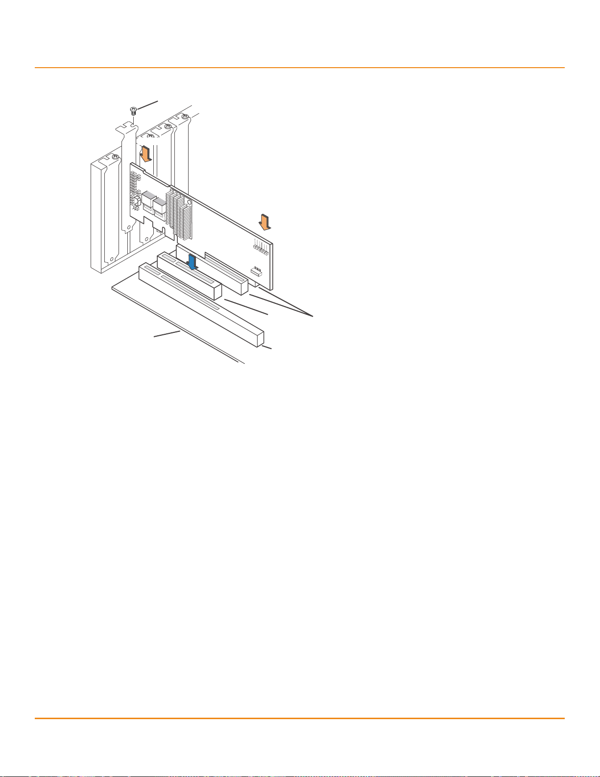
4. Install the RAID controller.
Select a PCIe slot, and align the controller’s PCIe bus connector to the slot. Press down gently, but firmly, to make
sure that the card is seated correctly in the slot. Secure the bracket to the computer chassis with the bracket screw.
The following figure shows the installation of the MegaRAID SAS 9260-8i RAID controller in a PCIe slot.
MegaRAID SAS Hardware Installation
Detailed Installation
AT T EN T IO N If your RAID controller has a battery backup unit (BBU) attached, do
not press down on the BBU when you insert the card.
NOTE This controller is a PCIe x8 card, and it can operate in x8 or x16 slots.
Some PCIe slots, however, support only PCIe graphics cards; if the
remote mount board is installed in one of these slots, the controller
will not function. Refer to the guide for your motherboard for
information about the PCIe slot.
LSI Corporation
- 21 -
Page 22
6Gb/s MegaRAID SAS RAID Controllers User Guide
85039-05
Edge of
Motherboard
32-bit slots
(3.3 V)
PCI-e
slot
Bracket Screw
64-bit slots
(3.3 V)
Press here
Press here
October 2013
Figure 3 Example of the MegaRAID SAS 9260-8i Board Installation in a PCI Express Slot
MegaRAID SAS Hardware Installation
Detailed Installation
5. Configure and install the SAS devices, the SATA devices, or both in the host computer case.
Refer to the documentation for the devices for any preinstallation configuration requirements.
6. Connect the RAID controller to the devices.
Use SAS cables to connect SAS devices, SATA devices, or both to the MegaRAID 6Gb/s SAS RAID controller. See
Section 2.5, SAS Device Cables and Connectors, for SAS cable and connector information. See Section 2.5.1,
Connecting a SAS RAID Controller with Internal Connectors to the Drives, for information about connecting the
controller to the drives.
The maximum cable length is 10 meters (393.37 in.). You can connect one device per SAS PHY unless you use
an expander.
System throughput problems can occur if the SAS cables are not the correct type. To minimize the potential for
problems, use the following guidelines:
— Use cables no longer than 10 meters (393.37 in.). (Use shorter cables, if possible.)
— Use cables that meet the SAS specification.
— Route the SAS cables carefully.
7. Turn on the power to the system.
Reinstall the computer cover, and reconnect the AC power cords. Turn on power to the host computer. Make sure
that the power is turned on to the SAS devices, SATA devices, or both before or at the same time that the power
is turned on to the host computer. If the computer is powered on before these devices, the devices might not
be recognized.
During boot, a BIOS message appears. The firmware takes several seconds to initialize. The configuration utility
prompt times out after several seconds. The second portion of the BIOS message shows the MegaRAID 6Gb/s SAS
RAID controller number, firmware version, and cache SDRAM size. The numbering of the controllers follows the
PCI slot scanning order used by the host motherboard.
LSI Corporation
- 22 -
Page 23

6Gb/s MegaRAID SAS RAID Controllers User Guide
October 2013
8. Run the WebBIOS Configuration Utility.
Run the WebBIOS Configuration Utility to configure the drive groups and the virtual drives. When the message
Press CTRL+H for WebBIOS appears on the screen, immediately press Ctrl+H to run the utility.
9. Install the operating system driver.
MegaRAID SAS RAID controllers can operate under various operating systems. To operate under these operating
systems, you must install the software drivers. The MegaRAID Universal Software Suite CD includes software drivers
for the supported operating systems, along with documentation. You can view the supported operating systems
and download the latest drivers for RAID controllers from the LSI website.
For information about installing the driver, refer to the MegaRAID SAS Device Driver Installation User Guide on the
MegaRAID Universal Software Suite CD. Be sure to use the latest service packs provided by the operating system
manufacturer and to review the readme file that accompanies the driver.
2.4 After Installing the RAID Controller
After you install the MegaRAID 6Gb/s SAS RAID controller, you must configure the controller and install the operating
system driver. The MegaRAID SAS Software User Guide instructs you on the configuration options and how to set them
on your MegaRAID 6Gb/s SAS RAID controller. The MegaRAID SAS Device Driver Installation User Guide provides
detailed installation instructions for operating system drivers.
MegaRAID SAS Hardware Installation
After Installing the RAID Controller
2.5 SAS Device Cables and Connectors
This section describes the cables and the connectors used on the MegaRAID SAS controllers and provides
step-by-step instructions for connecting SAS drives, SATA drives, or both to the MegaRAID SAS RAID controller. The
SAS protocol and the SATA protocol use a thin, 7-wire connector instead of the 68-wire SCSI cable or the 40-wire
ATA cable.
NOTE Use only straight SAS cables, not crossover SAS cables.
The following figure shows the SAS cable that connects the internal connectors on a SAS RAID controller to SAS drives,
SATA drives, or both.
LSI Corporation
- 23 -
Page 24
6Gb/s MegaRAID SAS RAID Controllers User Guide
HDD
Connector
Power
Connector
85039-06
Device Plug
Connector
Host Receptacle
Connector
Serial ATA
Signal Connector
(pin 1)
Serial ATA
Power Connector
(pin 1)
October 2013
Figure 4 Internal SAS Cable for Connection to SAS Drives, SATA II Drives, or SATA III Drives
MegaRAID SAS Hardware Installation
SAS Device Cables and Connectors
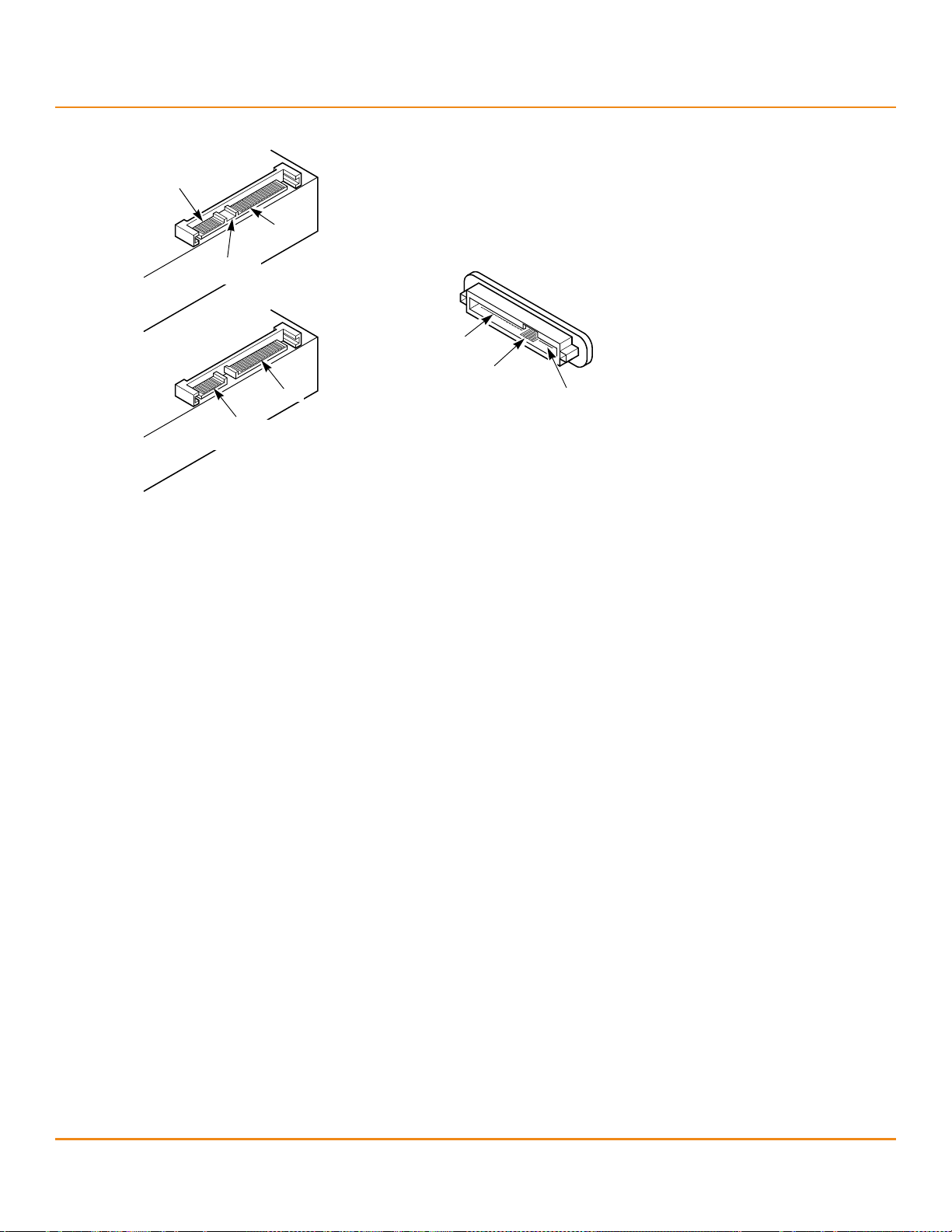
The following figure shows the SATA III device plug connector that connects a SAS RAID controller with internal
connectors to the host receptacle connector on a backplane. A SATA III connector consists of a signal connector and a
power connector.
Figure 5 SATA III Connectors
The following figure shows SAS connectors and SATA connectors on SAS drives and SATA drives, respectively. Cables
connect internal connectors on the RAID controllers to connectors on SAS drives, SATA drives, or both. Both SAS drives
and SATA drives can connect to SAS backplane receptacle connectors. The difference between the SAS connector and
the SATA connector is the bridge between the SAS primary physical link and the power connector on the SAS
controller, which the SATA connector does not have.
NOTE SAS backplane connectors accept SAS drives or SATA drives, but SATA
backplane connectors cannot accept SAS drives.
LSI Corporation
- 24 -
Page 25
6Gb/s MegaRAID SAS RAID Controllers User Guide
Serial ATA
SAS Primary
Physical Link
SAS Secondary
Physical Link
Power
SAT A II
Physical Link
Power
Serial Attached SCSI
SAS Backplane
Receptacle Connector
Note: SATA backplane connectors do
not accept SAS drives.
Power
SAS Secondary
Physical Link
SATA II/SAS
Primary
Physical Link
October 2013
Figure 6 SAS Plugs and SATA Plugs and SAS Backplane Receptacle Connector
MegaRAID SAS Hardware Installation
SAS Device Cables and Connectors
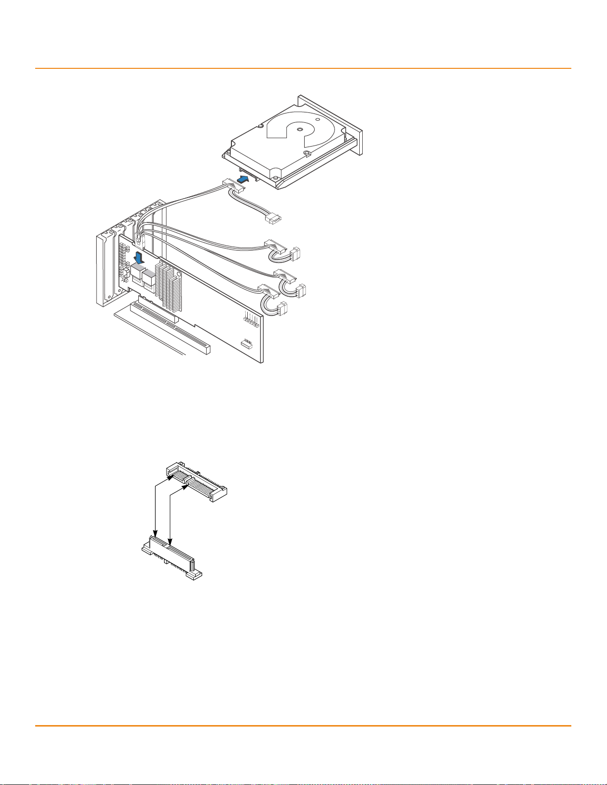
2.5.1 Connecting a SAS RAID Controller with Internal Connectors to the Drives
The following subsections provide step-by-step instructions for connecting the MegaRAID SAS RAID controllers to
SAS drives and SATA drives, either directly or through an expander.
This section provides step-by-step instructions for connecting the SAS cable from the internal connectors on the RAID
controller to SAS drives and SATA drives.
Follow these steps to connect your RAID controller with internal SAS port connectors directly to SAS drives or
SATA drives.
NOTE The MegaRAID SAS 9260-8i RAID controller is shown as an example.
You can connect other MegaRAID SAS controllers with internal SAS
port connectors in the same way.
1. Insert the SFF-8087 x4 internal mini SAS connector on the cable into a SFF-8087 x4 internal mini SAS connector
on the MegaRAID SAS 9260-8i RAID controller, as shown in the following figure.
2. Plug the HDD connector on the other end of the internal cable into the connector on the SAS drive or the
SATA drive.
3. If you have another drive, connect it to another plug on the internal cable.
You can connect other devices if the cable has more connectors.
LSI Corporation
- 25 -
Page 26

6Gb/s MegaRAID SAS RAID Controllers User Guide
HDD
Connector
Power
Connector
85039-06
October 2013
Figure 7 Connecting the MegaRAID SAS 9260-8i RAID Controller to a Drive
MegaRAID SAS Hardware Installation
SAS Device Cables and Connectors
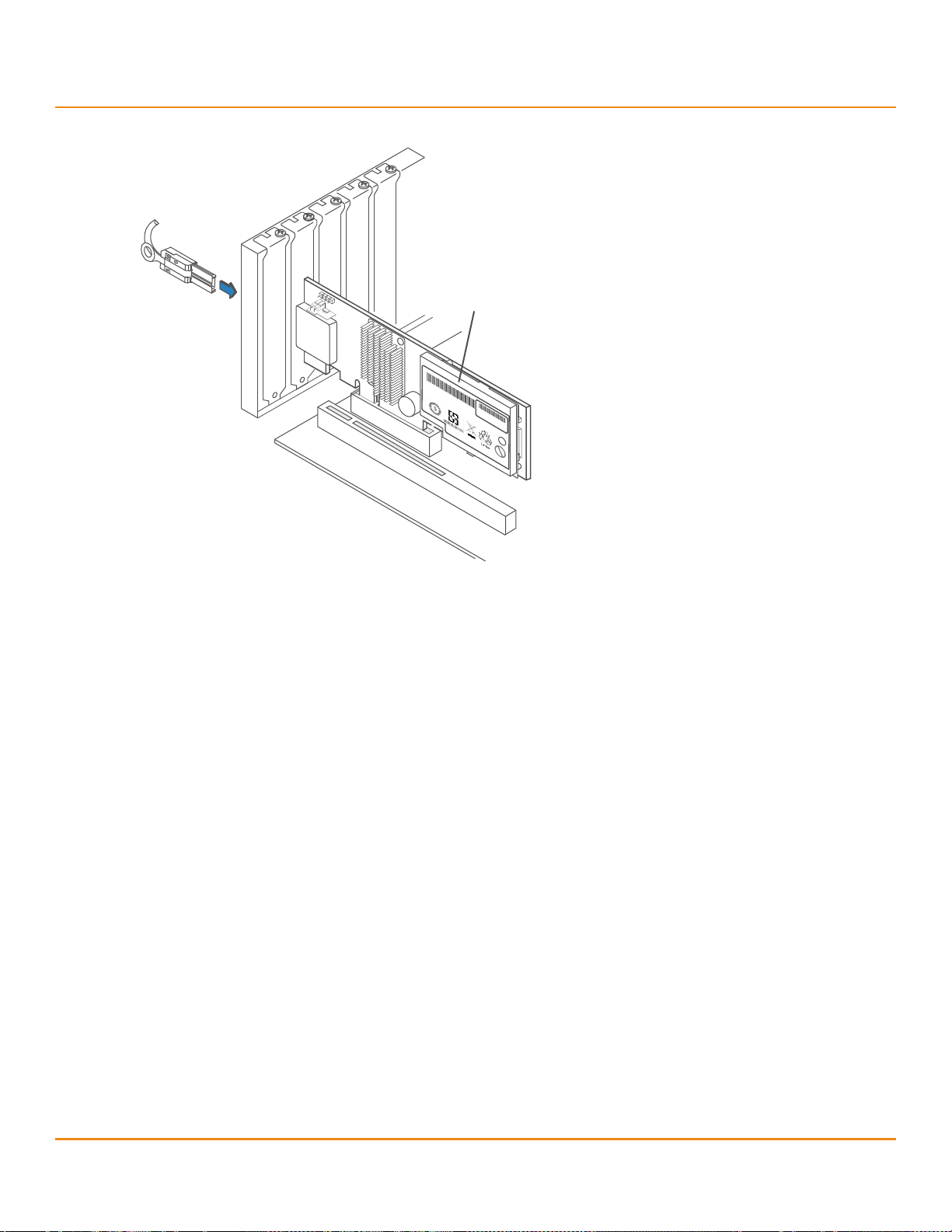
2.5.2 Connecting a RAID Controller with External Connectors to a Drive Enclosure
This section provides step-by-step instructions for connecting a MegaRAID SAS RAID controller with external SAS port
connectors to a drive enclosure containing SAS drives, SATA drives, or a combination of both drive types.
Follow these steps to connect the cable from your controller to a drive enclosure.
NOTE The following figure shows the MegaRAID SAS 9280-8e RAID
controller as an example. You can connect other MegaRAID SAS
controllers with external SAS port connectors in the same way.
1. Connect the connector on one end of the cable to external port J1A4 or J1B1 on the MegaRAID SAS 9280-8e RAID
controller, as shown in the following figure.
2. Connect the other end of the cable to the external port on the drive enclosure.
LSI Corporation
- 26 -
Page 27
6Gb/s MegaRAID SAS RAID Controllers User Guide
To Drive Enclosure
Mini SAS x4
Cable Plug
Connector
85040-10
iBBU (Top View)
Pb
LSI 31503-00 Rev. B
Caution:
Dangerof explosion if battery is incorrectly replaced.
Replacewith same or equivalent type recommended by manufacturer.
Dispose o
f u
sed
b
atteries
a
ccording
t
o
m
anufacturer's i
nstructions.
e1
Pb
ASSEMBLED
IN
USA.
WWYYN0000
October 2013
Figure 8 Connecting the MegaRAID SAS 9280-8e RAID Controller to a Drive Enclosure
MegaRAID SAS Hardware Installation
SAS Device Cables and Connectors
LSI Corporation
- 27 -
Page 28

6Gb/s MegaRAID SAS RAID Controllers User Guide
J4
J2
J6
85043-00
J5
J3
October 2013
MegaRAID SAS RAID Controller Characteristics
6Gb/s MegaRAID SAS RAID Controller Family
Chapter 3: MegaRAID SAS RAID Controller Characteristics
3.1 6Gb/s MegaRAID SAS RAID Controller Family
The 6Gb/s MegaRAID SAS RAID controllers are dual-PHY, SAS PCI Express RAID controllers and are used in a system
with a PCI Express slot. PCIe goes beyond the PCI specification in that it is intended as a unifying I/O architecture for
various systems: desktops, workstations, mobile devices, servers, communications, and embedded devices.
The following subsection provides figures and connector information for the 6Gb/s SAS RAID controllers.
3.1.1 MegaRAID SAS 9240 RAID Controllers
The MegaRAID SAS 9240-4i low-profile SAS/SATA RAID controller controls four internal SAS/SATA ports through one
SFF-8087 x4 internal mini SAS connector.
The MegaRAID SAS 9240-8i low-profile SAS/SATA RAID controller controls eight internal SAS/SATA ports through two
SFF-8087 x4 internal mini SAS connectors.
3.1.1.1 MegaRAID SAS 9240 RAID Controllers – Board Layout and Jumper and Connector Information
This subsection provides the board layout, and the connector and jumper information for the MegaRAID SAS 9240
RAID controllers. The following figure shows the jumpers and the connectors on the MegaRAID SAS 9240-8i
RAID controller.
NOTE The MegaRAID SAS 9240-4i RAID controller is like the MegaRAID SAS
9240-8i RAID controller except that the MegaRAID SAS 9240-4i RAID
controller does not contain the J5 connector, which supports
ports 4 to 7.
Figure 9 Card Layout for the MegaRAID SAS 9240-8i RAID Controller
LSI Corporation
- 28 -
Page 29

6Gb/s MegaRAID SAS RAID Controllers User Guide
October 2013
The following table describes the jumpers and the connectors on the MegaRAID SAS 9240-4i and MegaRAID SAS
9240-8i RAID controllers.
Table 3 MegaRAID SAS 9240-4i and MegaRAID SAS 9240-8i RAID Controllers – Jumpers and Connectors
Jumper Typ e Description
J1 RISCwatch header 16-pin header
J2 CPLD header 10-pin header
J3 External LED drive activity/fault header 4-pin connector
J4 x4 SAS Ports 0 to 3 SFF-8087 x4 internal mini SAS connector
J5 x4 SAS Ports 4 to 7 SFF-8087 x4 internal mini SAS connector
J6 PCIe x8 Board Edge connector x8 interface that provides connections on both the top and the bottom of
TP1 Universal Asynchronous
Receiver/Transmitter (UART)
debugging
MegaRAID SAS RAID Controller Characteristics
6Gb/s MegaRAID SAS RAID Controller Family
Reserved for LSI use.
Reserved for LSI use.
Connects to external, green or red LEDs that indicate drive activity or faults.
Connects the cables from the controller to SAS drives or SATA drives, or a
SAS expander.
Connects the cables from the controller to SAS drives or SATA drives, or a
SAS expander.
NOTE The MegaRAID SAS 9240-4i RAID controller does not have the
J5 connector.
the board.
4-pin connector
Reserved for LSI use.
3.1.2 MegaRAID SAS 9260 RAID Controllers
The MegaRAID SAS 9260-4i low-profile SAS/SATA RAID controller controls four internal SAS/SATA ports through one
SFF-8087 x4 internal mini SAS connector.
The MegaRAID SAS 9260-8i low-profile SAS/SATA RAID controller controls eight internal SAS/SATA ports through two
SFF-8087 x4 internal mini SAS connectors.
The MegaRAID SAS 9260CV-4i low-profile SAS/SATA RAID controller controls four internal SAS/SATA ports through one
SFF-8087 x4 internal mini SAS connector, and has a nonvolatile CVFM01 module attached. The CVFM01 module
connects to a CVPM01 module to provide backup for your data in case of power loss.
The MegaRAID SAS 9260CV-8i low-profile SAS/SATA RAID controller controls eight internal SAS/SATA ports through
two SFF-8087 x4 internal mini SAS connectors, and has a nonvolatile CVFM01 module attached. The CVFM01 module
connects to a CVPM01 module to provide backup for your data in case of power loss.
The MegaRAID SAS 9260DE-8i low-profile SAS/SATA RAID controller controls eight internal SAS/SATA ports through
two SFF-8087 x4 internal mini SAS connectors and offers data security by using disk encryption.
The MegaRAID SAS 9260-16i standard-height SAS/SATA RAID controller controls 16 internal SAS/SATA ports through
four SFF-8087 x4 internal mini SAS connectors.
LSI Corporation
- 29 -
Page 30

6Gb/s MegaRAID SAS RAID Controllers User Guide
3_01400-00
Port
3-0
JT10
JT3
JT4
JT2
JT1
JT12
JT8
JT13
JT11
JT9
Port
7-4
JT7 JT6
October 2013
MegaRAID SAS RAID Controller Characteristics
6Gb/s MegaRAID SAS RAID Controller Family
3.1.2.1 MegaRAID SAS 9260-4i, SAS 9260-8i, and SAS 9260DE-8i RAID Controllers – Board Layout and
Jumper/Connector Information
This subsection provides the board layout, and the connector and jumper information for the MegaRAID SAS 9260-4i,
SAS 9260-8i, and SAS 9260DE-8i RAID controllers. The following figure shows the connectors on the MegaRAID SAS
9260-8i RAID controller.
NOTE The MegaRAID SAS 9260-4i RAID controller has the same connectors
as the MegaRAID SAS 9260-8i RAID controller except for the JT7
connector, which supports ports 4 to 7. The MegaRAID SAS 9260DE-8i
RAID controller has the same connectors as the MegaRAID SAS 9260-8i
RAID controller.
Figure 10 Card Layout for the MegaRAID SAS 9260-8i RAID Controller
NOTE JT1, JT2, and JT4 are behind the LSIiBBU07 unit when the iBBU unit is
installed, but they are still accessible.
NOTE Pin 1 on the headers and connectors is highlighted in red in this figure.
The following table describes the jumpers and connectors on the MegaRAID SAS 9260-4i, SAS 9260-8i, and
SAS 9260DE-8i RAID controllers.
Table 4 MegaRAID SAS 9260-4i, SAS 9260-8i, and SAS 9260DE-8i RAID Controllers – Jumpers and Connectors
Jumper Typ e Description
JT1 Write-Pending Indicator (dirty cache)
LED connector
JT2 SAS Activity LED header 2-pin connector
JT3 Battery Backup Unit connector 20-pin connector
JT4 Global Drive Fault LED header 2-pin connector
JT6 x4 SAS Ports 3 to 0 SFF-8087 x4 internal mini SAS connector
2-pin connector
Connects to an LED that indicates when the data in the cache has yet to be
written to the storage devices. Used when the write-back feature is enabled.
Connects to an LED that indicates drive activity.
Connects the optional LSIiBBU07 intelligent Battery Backup Unit or the optional
LSIiBBU08 unit to the RAID controller remotely.
Connects to a single LED to indicate whether any drive is in a fault condition.
Connects the cables from the RAID controller to SAS drives, SATA drives, or a
SAS expander.
LSI Corporation
- 30 -
Page 31

6Gb/s MegaRAID SAS RAID Controllers User Guide
October 2013
Table 4 MegaRAID SAS 9260-4i, SAS 9260-8i, and SAS 9260DE-8i RAID Controllers – Jumpers and Connectors (Continued)
Jumper Typ e Description
JT7 x4 SAS Ports 7 to 4 SFF-8087 x4 internal mini SAS connector
JT8 Advanced Software Options Hardware
Key header
JT9 Set Factory Defaults connector 2-pin connector
JT10 LSI Test header 2-pin connector
JT11 IPMI-style SMBus (System
Management)/I
JT12 Individual Drive Fault LED header for
Eight Phys (0 to 7)
JT13 Universal Asynchronous
Receiver/Transmitter (UART)
debugging
2
C header
MegaRAID SAS RAID Controller Characteristics
6Gb/s MegaRAID SAS RAID Controller Family
Connects the cables from the RAID controller to SAS drives, SATA drives, or a
SAS expander.
NOTE The MegaRAID SAS 9260-4i RAID controller does not have this connector.
2-pin connector
Enables support for the Advanced Software Options features, which include
CacheCade, Recovery, and SafeStore™ disk encryption.
NOTE FastPath is now a standard feature for this controller.
Reserved for LSI use.
Reserved for LSI use.
3-pin shielded header
Provides enclosure management support.
16-pin connector
Indicates drive faults. There is one LED per port. When lit, each LED indicates the
corresponding drive has failed or is in the Unconfigured-Bad state. Refer to the
MegaRAID SAS Software User Guide for more information about drive states.
The LEDs function in a direct-attach configuration (there are no SAS expanders).
Direct attach is defined as a maximum of one drive connected directly to
each port.
NOTE This header is used for RAID controllers with internal SAS ports only.
4-pin connector
Reserved for LSI use.
LSI Corporation
- 31 -
Page 32

6Gb/s MegaRAID SAS RAID Controllers User Guide
85068-00
J2B1
Ports
0-3
J2B2
Ports
4-7
J3B1
Ports
8-11
J4B2
Ports
12-15
J1A2
J1B1
J1B3
J1C1
J2D1
J4A2
J5A2
J4A3
J5B3
J4A1
J4A4
October 2013
MegaRAID SAS RAID Controller Characteristics
6Gb/s MegaRAID SAS RAID Controller Family
3.1.2.2 MegaRAID SAS 9260-16i RAID Controller – Board Layout and Jumper/Connector Information
This subsection provides the board layout, and the connector and jumper information for the MegaRAID SAS
9260-16i RAID controller. The following figure shows the jumpers and connectors on the MegaRAID SAS 9260-16i
RAID controller.
Figure 11 Card Layout for the MegaRAID SAS 9260-16i RAID Controller
NOTE Pin 1 on the headers and connectors is highlighted in red in this figure.
LSI Corporation
- 32 -
Page 33

6Gb/s MegaRAID SAS RAID Controllers User Guide
J1B1
PORT 0
PORT 7
+ve
-ve
ak
October 2013
The following table describes the jumpers and the connectors on the MegaRAID SAS 9260-16i RAID controller. It
includes diagrams that show Pin1 and its orientation for several of the connectors.
Table 5 MegaRAID SAS 9260-16i RAID Controller – Connectors
MegaRAID SAS RAID Controller Characteristics
6Gb/s MegaRAID SAS RAID Controller Family
Jumper/
Connector
Typ e Description
J1A2 Universal Asynchronous Receiver/Transmitter (UART)
for the Expander
J1B1 LED Locate and Fault Indication header
Ports 0 to 3
Ports 4 to 7
4-pin connector
Reserved for LSI use.
2x8-pin connector
Connects to an LED array that indicates whether a drive is in
a fault condition. There is one LED per port. When lit, each
LED indicates the corresponding drive has failed or is in the
unconfigured-bad state.
The LEDs function in a direct-attach configuration (there are
no SAS expanders). Direct attach is defined as a maximum of
one drive connected directly to each port.
NOTE This header is used for RAID controllers with internal
SAS ports only.
J1B3 Advanced Software Options Hardware Key header 2-pin header
Enables support for the Advanced Software Options
features, which include CacheCade, Recovery, and SafeStore
disk encryption.
NOTE FastPath is now a standard feature for this controller.
J1C1
IPMI-style I
2
C connector
J1L1 Remote Battery Backup connector (on the rear of the
controller)
3-pin connector
Supports SES (SCSI enclosure services) over I
internal I
2
C backplane cable.
2
C through an
20-pin connector
Connects the optional LSIiBBU07 intelligent Battery
Backup Unit or the optional LSIiBBU08 unit to the RAID
controller remotely.
J2B1 x4 SAS Ports 0 to 3 Internal connector SFF-8087 x4 internal mini SAS connector
Connects the controller by cable to SAS drives or
SATA 2 drives.
J2B2 x4 SAS Ports 4 to 7 Internal connector SFF-8087 x4 internal mini SAS connector
Connects the controller by cable to SAS drives or
SATA 2 drives.
J2D1 Standard Edge Card connector The RAID controller interfaces with the host system though a
standard edge card.
2
This interface provides power to the board and an I
interface connected to the I
2
C bus for IPMI.
C
LSI Corporation
- 33 -
Page 34

6Gb/s MegaRAID SAS RAID Controllers User Guide
J4A2
+ve
ak
-ve
J4A3
ak
+ve -ve
J4A4
PORT 8
PORT 15
+ve-ve
ka
October 2013
Table 5 MegaRAID SAS 9260-16i RAID Controller – Connectors (Continued)
MegaRAID SAS RAID Controller Characteristics
6Gb/s MegaRAID SAS RAID Controller Family
Jumper/
Connector
Typ e Description
J3B1 x4 SAS Ports 8-11 internal connector SFF-8087 x4 internal mini SAS connector
Connects the controller by cable to SAS drives or
SATA 2 drives.
J4A1 Module CPLD 1x8-pin connector
Reserved for LSI use.
J4A2 Activity LED header 2-pin connector
Connects to an LED that indicates activity on the drives
connected to the controller.
J4A3 Global Drive Fault LED header 2-pin connector
Connects to an LED that indicates whether a drive is in a
fault condition.
J4A4 LED Locate and Fault Indication header
Ports 8 to 11
Ports 12 to 15
2x8-pin header
Connects to an LED array that indicates whether a drive is in
a fault condition. There is one LED per port. When lit, each
LED indicates the corresponding drive has failed or is in the
Unconfigured-Bad state.
The LEDs function in a direct-attach configuration (there are
no SAS expanders). Direct attach is defined as a maximum of
one drive connected directly to each port.
NOTE This header is used for RAID controllers with internal
SAS ports only.
LSI Corporation
- 34 -
Page 35

6Gb/s MegaRAID SAS RAID Controllers User Guide
J5A2
ak
+ve -ve
85081-00
JT1A1
JT1A2
JT1A3
Ports 3-0Ports 7-4
JT1A4
JT1B1
JT2B1
JT2B2
JT1B2
JT6A1
JT6A2
JT6A3
J5A1
October 2013
Table 5 MegaRAID SAS 9260-16i RAID Controller – Connectors (Continued)
MegaRAID SAS RAID Controller Characteristics
6Gb/s MegaRAID SAS RAID Controller Family
Jumper/
Connector
Typ e Description
J4B2 x4 SAS Ports 12 to 15 Internal connector SFF-8087 x4 internal mini SAS connector
Connects the controller by cable to SAS drives or
SATA 2 drives.
J5A2 Write-Pending LED header 2-pin connector
Connects to an LED that indicates when the data in the
cache has yet to be written to the storage devices. Used
when the write-back feature is enabled.
J5B3 Universal Asynchronous Receiver/Transmitter (UART)
debugging
4-pin connector
Reserved for LSI use.
3.1.2.3 MegaRAID SAS 9260CV-4i and MegaRAID SAS 9260CV-8i RAID Controllers – Board Layout and
Jumper/Connector Information
This subsection provides the board layout, and connector and jumper information for the RAID controller. The
following figure shows the location of the jumpers and the connectors on the MegaRAID SAS 9260CV-8i RAID
controller. The jumpers are set at the factory, and you usually do not need to change them.
NOTE The MegaRAID SAS 9260CV-4i RAID controller does not contain the
JT2B1 connector, which supports ports 4 to 7. The JT2B1 connector is
on the MegaRAID SAS 9260CV-8i RAID controller.
Figure 12 Card Layout for the MegaRAID SAS 9260CV-8i RAID Controller
NOTE Pin 1 on the headers and connectors is highlighted in red in this figure.
LSI Corporation
- 35 -
Page 36

6Gb/s MegaRAID SAS RAID Controllers User Guide
JT1A1
PORT 0
PORT 7
+ve
-ve
ak
October 2013
The following table describes the jumpers and the connectors on the MegaRAID SAS 9260CV-8i RAID controller.
Table 6 MegaRAID SAS 9260CV-4i and MegaRAID SAS 9260CV-8i RAID Controllers – Jumpers and Connectors
MegaRAID SAS RAID Controller Characteristics
6Gb/s MegaRAID SAS RAID Controller Family
Jumper/
Connector
Typ e Description
J5A1 Board-to-Board Mezzanine connector 240-pin 01 nonvolatile memory module interface
Connects the controller directly to a CVFM01 module. The
CVFM01 module connects to a remote CVPM01 module.
Refer to the MegaRAID SAS 9260CV-4i and SAS 9260CV-8i RAID
Controllers Quick Installation Guide for the procedure used to
connect a CVFM01 module to a remote CVPM01 module.
JT1A1 LED Locate and Fault Indication header
Ports 0 to 3
Ports 4 to 7
2x8-pin header
Connects to an LED array that indicates whether a drive is in
a fault condition. There is one LED per port. When lit, each
LED indicates the corresponding drive has failed or is in the
Unconfigured-Bad state.
The LEDs function in a direct-attach configuration (there are
no SAS expanders). Direct attach is defined as a maximum of
one drive connected directly to each port.
NOTE The MegaRAID SAS 9260CV-4i RAID controller does
not contain the JT2B1 connector, which supports ports 4 to 7.
JT1A2 LSI Internal Use header Reserved for LSI internal use.
JT1A3 SBR Firmware Recovery header 2-pin header
The SBR FW recovery header is used when SBR corruption is
suspected. Installing the jumper lets the unit boot while
bypassing the SBR information. You can then reprogram the
SEEPROM using external utility software. No jumper is
present for normal operation.
JT1A4 Serial UART header Reserved for LSI internal use.
JT1B1 SEP Enclosure Support header 3-pin header
Used for connection to the Port0 enclosure.
JT1B2 Advanced Software Options Hardware Key header 2-pin header
Enables support for the Advanced Software Options
features, which include CacheCade, Recovery, and SafeStore
disk encryption.
NOTE FastPath is now a standard feature for this controller.
JT2B1 x4 SAS Ports 4 to 7 Mini-SAS 4i Internal connector SFF-8087 x4 internal mini SAS connector
Connects the controller by cable to SAS drives or
SATA 2 drives.
NOTE The MegaRAID SAS 9260CV-4i RAID controller does
not contain the JT2B1 connector.
LSI Corporation
- 36 -
Page 37

6Gb/s MegaRAID SAS RAID Controllers User Guide
JT6A1
ak
+ve
-ve
JT6A2
+ve
ak
-ve
JT6A3
ak
+ve -ve
October 2013
Table 6 MegaRAID SAS 9260CV-4i and MegaRAID SAS 9260CV-8i RAID Controllers – Jumpers and Connectors (Continued)
MegaRAID SAS RAID Controller Characteristics
6Gb/s MegaRAID SAS RAID Controller Family
Jumper/
Connector
Typ e Description
JT2B2 x4 SAS Ports 0 to 3 Mini-SAS 4i Internal connector SFF-8087 x4 internal mini SAS connector
Connects the controller by cable to SAS drives or
SATA 2 drives.
JT2B3 Standard Edge Card connector The RAID controller interfaces with the host system though a
standard edge card.
2
This interface provides power to the board and an I
C
interface connected to the I2C bus for IPMI.
JT6A1 Global Drive Fault LED header 2-pin connector
Connects to an LED that indicates whether a drive is in a
fault condition.
JT6A2 Hard Disk Drive Activity LED header 2-pin connector
Connects to an LED that indicates activity on the drives
connected to the controller.
JT6A3 Write-Pending LED header 2-pin connector
Connects to an LED that indicates when the data in the
cache has yet to be written to the storage devices. Used
when the write-back feature is enabled.
LSI Corporation
- 37 -
Page 38

6Gb/s MegaRAID SAS RAID Controllers User Guide
October 2013
MegaRAID SAS RAID Controller Characteristics
6Gb/s MegaRAID SAS RAID Controller Family
3.1.3 MegaRAID SAS 9261 RAID Controller
The MegaRAID SAS 9261-8i low-profile SAS/SATA RAID controller controls eight internal SAS/SATA ports through two
SFF-8087 mini-SAS 4i connectors.
3.1.3.1 MegaRAID SAS 9261-8i RAID Controller – Board Layout and Jumper/Connector Information
This subsection provides the board layout, and the connector and jumper information for the MegaRAID
SAS 9261-8i RAID controller. The following figure shows the jumpers and connectors on the MegaRAID SAS 9261-8i
RAID controller.
Figure 13 Card Layout for the MegaRAID SAS 9261-8i RAID Controller
The following table describes the jumpers and the connectors on the MegaRAID SAS 9261-8i RAID controller.
Table 7 MegaRAID SAS 9261-8i RAID Controller – Jumpers and Connectors
Jumper Typ e Description
J4L1 Remote Battery Backup Unit connector
(on the rear of the controller)
JT3B1 Battery Backup Unit connector 20-pin connector
JT5A1 x4 SAS Ports 0 to 3
Mini-SAS 4i connector
JT5B1 x4 SAS Ports 4 to 7
Mini-SAS 4i connector
JT5B2 Universal Asynchronous
Receiver/Transmitter (UART)
debugging
JT5B3 Set Factory Defaults connector 2-pin connector
JT6B1 Test header 2-pin connector
JT6B2 Global Drive Fault LED header 2-pin connector
JT6B3 SAS Activity LED header 2-pin connector
20-pin connector
Connects an optional remote LSIiBBU07 intelligent Battery Backup Unit or an
LSIiBBU08 unit to the RAID controller.
Connects an optional LSIiBBU07 intelligent Battery Backup Unit or an optional
LSIiBBU08 unit directly to the RAID controller.
Connects the cables from the RAID controller to SAS drives or SATA drives, or a
SAS expander.
Connects the cables from the RAID controller to SAS drives or SATA drives, or a
SAS expander.
4-pin connector
Reserved for LSI use.
Reserved for LSI use.
Reserved for LSI use.
Connects to an LED that indicates whether a drive is in a fault condition.
Connects to an LED that indicates drive activity.
LSI Corporation
- 38 -
Page 39

6Gb/s MegaRAID SAS RAID Controllers User Guide
85079-00
J2B1 J2B2
J1A1
J1A2
J1A3
J1A4
J1A5
J1A7
J2B3
J2B4
J5B1
J5A1
J6A1
October 2013
MegaRAID SAS RAID Controller Characteristics
6Gb/s MegaRAID SAS RAID Controller Family
3.1.4 MegaRAID SAS 9265 RAID Controllers
The 6Gb/s MegaRAID SAS 9265-8i low-profile SAS/SATA RAID controller controls eight internal SAS/SATA ports
through two SFF-8087 x4 internal mini SAS connectors.
The 6Gb/s MegaRAID SAS 9265CV-8i low-profile SAS/SATA RAID controller controls eight internal SAS/SATA ports
through two SFF-8087 x4 internal mini SAS connectors. This controller supports a CacheVault Flash Module, CVFM03,
that connects to a CVPM02 module to provide backup for your data in case of power loss.
3.1.4.1 MegaRAID SAS 9265-8i RAID Controller – Board Layout and Jumper/Connector Information
This subsection provides the board layout, and the connector and jumper information for the MegaRAID SAS 9265-8i
RAID controller. The following figure shows the location of the jumpers and the connectors on the MegaRAID SAS
9265-8i RAID controller. The jumpers are set at the factory, and you usually do not need to change them.
Figure 14 Card Layout for the MegaRAID SAS 9265-8i RAID Controller
NOTE Pin 1 on the headers and connectors is highlighted in red in this figure.
LSI Corporation
- 39 -
Page 40

6Gb/s MegaRAID SAS RAID Controllers User Guide
J1A1
ak
+ve
-ve
J1A2
ak
+ve
-ve
J1A4
+ve
ak
-ve
J1A5
+ve
-ve
a
k
October 2013
The following table describes the jumpers and the connectors on the MegaRAID SAS 9265-8i RAID controller.
Table 8 MegaRAID SAS 9265-8i RAID Controller – Jumpers and Connectors
MegaRAID SAS RAID Controller Characteristics
6Gb/s MegaRAID SAS RAID Controller Family
Jumper/
Connector
J1A1 Global Drive Fault LED header 2-pin connector
J1A2 Write-Pending LED header 2-pin connector
J1A3 LSI Test header 2-pin connector
J1A4 Activity LED header 2-pin connector
Typ e Description
Connects to an LED that indicates whether a drive is in a
fault condition.
Connects to an LED that indicates when the data in the
cache has yet to be written to the storage devices. Used
when the write-back feature is enabled.
Reserved for internal use.
Connects to an LED that indicates activity on the drives
connected to the controller.
J1A5 Individual PHY and Drive Fault Indication header
Ports 0 to 3
Ports 4 to 7
LSI Corporation
- 40 -
2x8-pin header
Connects to an LED that indicates whether a drive is in a
fault condition. There is one LED per port. When lit, each LED
indicates the corresponding drive has failed or is in the
Unconfigured-Bad state.
The LEDs function in a direct-attach configuration (there are
no SAS expanders). Direct attach is defined as a maximum of
one drive connected directly to each port.
Page 41

6Gb/s MegaRAID SAS RAID Controllers User Guide
J1A7
1
2
3
October 2013
Table 8 MegaRAID SAS 9265-8i RAID Controller – Jumpers and Connectors (Continued)
MegaRAID SAS RAID Controller Characteristics
6Gb/s MegaRAID SAS RAID Controller Family
Jumper/
Connector
J1A7
2
C Enclosure Management connector
I
Typ e Description
3-pin connector
Supports SES (SCSI enclosure services) over I
2
C through an
internal I2C backplane cable.
J1B1 Serial EEPROM (SBR) 2-pin connector
Provides controller information, such as the serial number,
revision, and manufacturing date. The default is no shunt
installed.
J2B1 x4 SAS Ports 0 to 3 Internal connector SFF-8087 mini SAS 4i internal connector
Connects the controller by cable to SAS drives or
SATA 2 drives.
J2B2 x4 SAS Ports 4 to 7 Internal connector SFF-8087 mini SAS 4i internal connector
Connects the controller by cable to SAS drives or
SATA 2 drives.
J2B3 Advanced Software Options Hardware Key header 3-pin header
Enables support for the Advanced Software Options
features, which include CacheCade, Recovery, and SafeStore
disk encryption.
NOTE FastPath is now a standard feature for this controller.
J2B4 Standard Edge Card connector The RAID controller interfaces with the host system though a
standard edge card.
2
This interface provides power to the board and an I
C
interface connected to the I2C bus for IPMI.
J5A1 Serial Universal Asynchronous Receiver/Transmitter
(UART) connector for the Expander
4-pin connector
Reserved for LSI use.
J5B1 Board-to-board Mezzanine connector 240-pin DDR3 nonvolatile memory module interface
Connects the controller directly to a CVFM module. The
CVFM module can connect to an optional remote LSIiBBU09
intelligent battery backup unit.
Refer to the MegaRAID LSIiBBU09 Intelligent Battery Backup
Unit Quick Installation Guide for the procedure used to
connect a CVFM module to a remote LSIiBBU09 unit.
J6A1 Serial Universal Asynchronous Receiver/Transmitter
(UART) connector for the expander
4-pin connector
Reserved for LSI use.
LSI Corporation
- 41 -
Page 42

6Gb/s MegaRAID SAS RAID Controllers User Guide
3_00792-00
J2B1 J2B2
J1A1
J1A2
J1A3
J1A4
J1A5
J1A7
J2B4
J5B1
J5A1
J6A1
J1B1
J2B3
J1A8
J1A1
ak
+ve
-ve
J1A2
ak
+ve
-ve
October 2013
MegaRAID SAS RAID Controller Characteristics
6Gb/s MegaRAID SAS RAID Controller Family
3.1.4.2 MegaRAID SAS 9265CV-8i RAID Controller – Board Layout and Jumper/Connector Information
This subsection provides the board layout, and the connector and jumper information for the MegaRAID
SAS 9265CV-8i RAID controller.
The following figure shows the location of the jumpers and the connectors on the MegaRAID SAS 9265CV-8i RAID
controller. The jumpers are set at the factory, and you usually do not need to change them.
Figure 15 Card Layout for the MegaRAID SAS 9265CV-8i RAID Controller
NOTE Pin 1 on the headers and connectors is highlighted in red in this figure.
The following table describes the jumpers and the connectors on the MegaRAID SAS 9265CV-8i RAID controller.
Table 9 MegaRAID SAS 9265CV-8i RAID Controller – Jumpers and Connectors
Jumper/
Connector
J1A1 Global Drive Fault LED header 2-pin connector
J1A2 Write-Pending LED header 2-pin connector
J1A3 LSI Test header 2-pin connector
Typ e Description
Connects to an LED that indicates whether a drive is in a
fault condition.
Connects to an LED that indicates when the data in the
cache has yet to be written to the storage devices. Used
when the write-back feature is enabled.
Reserved for internal use.
LSI Corporation
- 42 -
Page 43

6Gb/s MegaRAID SAS RAID Controllers User Guide
J1A4
+ve
ak
-ve
J1A5
+ve
-ve
a
k
J1A7
1
2
3
October 2013
Table 9 MegaRAID SAS 9265CV-8i RAID Controller – Jumpers and Connectors (Continued)
MegaRAID SAS RAID Controller Characteristics
6Gb/s MegaRAID SAS RAID Controller Family
Jumper/
Connector
Typ e Description
J1A4 Activity LED header 2-pin connector
Connects to an LED that indicates activity on the drives
connected to the controller.
J1A5 Individual PHY and Drive Fault Indication header
Ports 0 to 3
Ports 4 to 7
2x8-pin header
Connects to an LED that indicates whether a drive is in a
fault condition. There is one LED per port. When lit, each LED
indicates the corresponding drive has failed or is in the
Unconfigured-Bad state.
The LEDs function in a direct-attach configuration (there are
no SAS expanders). Direct attach is defined as a maximum of
one drive connected directly to each port.
J1A7
2
C Enclosure Management connector
I
3-pin connector
Supports SES (SCSI enclosure services) over I2C through an
2
internal I
C backplane cable.
J1B1 Serial EEPROM (SBR) 2-pin connector
Provides controller information, such as the serial number,
revision, and manufacturing date. The default is no
shunt installed.
J2B1 x4 SAS Ports 0 to 3 Internal connector SFF-8087 mini SAS 4i internal connector
Connects the controller by cable to SAS drives or
SATA drives.
J2B2 x4 SAS Ports 4 to 7 Internal connector SFF-8087 mini SAS 4i internal connector
Connects the controller by cable to SAS drives or
SATA drives.
LSI Corporation
- 43 -
Page 44

6Gb/s MegaRAID SAS RAID Controllers User Guide
October 2013
Table 9 MegaRAID SAS 9265CV-8i RAID Controller – Jumpers and Connectors (Continued)
MegaRAID SAS RAID Controller Characteristics
6Gb/s MegaRAID SAS RAID Controller Family
Jumper/
Connector
Typ e Description
J2B3 Advanced Software Options Hardware Key header 3-pin header
Enables support for the Advanced Software Options
features, which include CacheCade, Recovery, and SafeStore
disk encryption.
NOTE FastPath is now a standard feature for this controller.
J2B4 Standard Edge Card connector The RAID controller interfaces with the host system though a
standard edge card.
2
This interface provides power to the board and an I
C
interface connected to the I2C bus for IPMI.
J5A1 Serial Universal Asynchronous Receiver/Transmitter
(UART) connector for the expander
4-pin connector
Reserved for LSI use.
J5B1 Board-to-Board Mezzanine connector 240-pin 02 DDR3 nonvolatile memory module interface
Connects a CacheVault Flash Module, CVFM03, directly to
the RAID controller. The CVFM03 module connects to a
CacheVault Power Module 02, CVPM02, that is mounted on a
remote mount board.
Refer to the MegaRAID SAS 9265CV-8e RAID Controller Quick
Installation Guide for the procedure used to connect the
CVFM03 module to the CVPM02 module.
J6A1 Serial Universal Asynchronous Receiver/Transmitter
(UART) connector for the expander
4-pin connector
Reserved for LSI use.
3.1.5 MegaRAID SAS 9266 RAID Controllers
The MegaRAID SAS 9266-4i low-profile SAS/SATA RAID controller controls four internal SAS/SATA ports through one
SFF-8087 mini SAS 4i internal connector.
The MegaRAID SAS 9266-8i low-profile SAS/SATA RAID controller controls eight internal SAS/SATA ports through two
SFF-8087 mini SAS 4i internal connectors. This controller supports a nonvolatile CVFM02 module that connects to a
CVPM02 module to provide backup for your data in case of power loss.
NOTE The MegaRAID SAS 9266-4i RAID controller does not contain the J5B1
connector, which supports ports 4 to 7. The J5B1 connector is on the
MegaRAID SAS 9266-8i RAID controller.
LSI Corporation
- 44 -
Page 45

6Gb/s MegaRAID SAS RAID Controllers User Guide
3_00890-03
J3A1
J4B1
J6B5 J6B3
J6B6
J6B4
J6B2
J6B1
J1A3
J2B4
J1A2
J1A4
J1B1
J5A1
J5B1
J3L1
J5A2
October 2013
MegaRAID SAS RAID Controller Characteristics
6Gb/s MegaRAID SAS RAID Controller Family
3.1.5.1 MegaRAID SAS 9266 RAID Controller – Board Layout and Jumper/Connector Information
This subsection provides the board layout, and the connector and jumper information for the MegaRAID SAS 9266-8i
RAID controller. The MegaRAID SAS 9266-4i RAID controller is the same as the MegaRAID SAS 9266-8i RAID controller,
except that it does not support the J5B1 port connector.
The following figure shows the jumpers and the connectors on the RAID controller. The jumpers are set at the factory,
and you usually do not need to change them.
Figure 16 Card Layout for the MegaRAID SAS 9266-8i RAID Controller
The following table describes the jumpers and the connectors on the MegaRAID SAS 9266 RAID controller.
Table 10 MegaRAID SAS 9266 RAID Controllers – Jumpers and Connectors
Jumper/
Connector
J1A2 SCS Backplane Management connector 3-pin shielded header
J1A3 Local Battery Backup Unit connector 20-pin connector
J1A4 SCS Backplane Management connector 3-pin shielded header
J1B1 Individual PHY and Drive Fault Indication
header
Ports 3 to 0
Ports 7 to 4
Typ e Description
Implements an enclosure management module that is responsible
for providing enclosure management functions for storage
enclosures and server backplanes.
Connects the LSIiBBU09 unit directly to the RAID controller.
Implements an enclosure management module that is responsible
for providing enclosure management functions for storage
enclosures and server backplanes.
2x8-pin header
Connects to an LED that indicates whether a drive is in a fault
condition. There is one LED per port. When lit, each LED
indicates the corresponding drive has failed or is in the
Unconfigured-Bad state.
The LEDs function in a direct-attach configuration (there are no
SAS expanders). Direct attach is defined as a maximum of one
drive connected directly to each port.
LSI Corporation
- 45 -
Page 46

6Gb/s MegaRAID SAS RAID Controllers User Guide
October 2013
Table 10 MegaRAID SAS 9266 RAID Controllers – Jumpers and Connectors (Continued)
MegaRAID SAS RAID Controller Characteristics
6Gb/s MegaRAID SAS RAID Controller Family
Jumper/
Connector
Typ e Description
J2B4 Standard Edge Card connector The interface between the RAID controller and the host system.
This interface provides power to the board and an I
2
C interface
connected to the I2C bus for the Intelligent Platform Management
Interface (IPMI).
J3A1 Drive Activity LED header 2-pin connector
This connector is not used.
J3L1 Remote Battery Backup connector 20-pin connector
Connects a remote LSIiBBU09 unit to RAID controller.
J4B1 CacheVault Flash Module DDR3 interface 70-pin connector
Connects the RAID controller to a CVFM02 module. The CVFM02
module connects to a remote CVPM02 module.
J5A1 x4 SAS Port 0 through Port 3 Internal connector SFF-8087 mini SAS 4i internal connector
Connects the controller by cable to SAS drives or SATA drives.
J5A2 Write-Pending LED header 2-pin connector
Connects to an LED that indicates when the data in the cache has
yet to be written to the storage devices. Used when the write-back
feature is enabled.
J5B1 x4 SAS Ports 4 to 7 Internal connector SFF-8087 mini SAS 4i internal connector
Connects the controller by cable to SAS drives or SATA drives.
NOTE The MegaRAID SAS 9266-4i RAID controller does not contain
the J5B1 connector.
J6B1 Advanced Software Options Hardware Key
header
3-pin header
Enables support for the Advanced Software Options features,
which include CacheCade, Recovery, and SafeStore
disk encryption.
NOTE FastPath is now a standard feature for this controller.
J6B2 SBR Bypass header 2-pin connector
Lets you bypass the SBR EEPROM during boot in case the EEPROM
contents are corrupt or missing.
J6B3 Global Activity LED header 2-pin header
Connects to a single LED that indicates drive activity on
either port.
J6B4 Onboard Serial Universal Asynchronous
Receiver/Transmitter (UART) connector
4-pin connector
Reserved for LSI use.
J6B5 Global Drive Fault LED indicator 2-pin header
Connects to a single LED that indicates drive activity on
either port.
J6B6 Onboard Serial Universal Asynchronous
Receiver/Transmitter (UART) connector
4-pin connector
Reserved for LSI use.
LSI Corporation
- 46 -
Page 47

6Gb/s MegaRAID SAS RAID Controllers User Guide
85079-00
J2B1 J2B2
J1A1
J1A2
J1A3
J1A4
J1A5
J1A7
J2B3
J2B4
J5B1
J5A1
J6A1
J1A1
ak
+ve
-ve
J1A2
ak
+ve
-ve
October 2013
MegaRAID SAS RAID Controller Characteristics
6Gb/s MegaRAID SAS RAID Controller Family
3.1.6 MegaRAID SAS 9270 RAID Controller
The MegaRAID SAS 9270-8i low-profile SAS/SATA disk array controller controls eight internal SAS/SATA ports through
two SFF-8087 mini-SAS 4i internal connectors.
3.1.6.1 MegaRAID SAS 9270-8i RAID Controller – Board Layout and Jumper/Connector Information
This subsection provides the board layout, and the connector and jumper information for the MegaRAID SAS 9270-8i
RAID controller. The following figure shows the location of the jumpers and the connectors on the MegaRAID
SAS 9270-8i RAID controller. The jumpers are set at the factory, and you usually do not need to change them.
Figure 17 Card Layout for the MegaRAID SAS 9270-8i RAID Controller
NOTE Pin 1 on the headers and connectors is highlighted in red in this figure.
The following table describes the jumpers and the connectors on the MegaRAID SAS 9270-8i RAID controller.
Table 11 MegaRAID SAS 9270-8i RAID Controller – Jumpers and Connectors
Jumper/
Connector
J1A1 Global Drive Fault LED header 2-pin connector
J1A2 Write-Pending LED header 2-pin connector
Typ e Description
Connects to an LED that indicates whether a drive is in a
fault condition.
Connects to an LED that indicates when the data in the
cache has yet to be written to the storage devices. Used
when the write-back feature is enabled.
J1A3 LSI Test header 2-pin connector
Reserved for internal use.
LSI Corporation
- 47 -
Page 48

6Gb/s MegaRAID SAS RAID Controllers User Guide
J1A4
+ve
ak
-ve
J1A5
+ve
-ve
a
k
J1A7
1
2
3
October 2013
Table 11 MegaRAID SAS 9270-8i RAID Controller – Jumpers and Connectors (Continued)
MegaRAID SAS RAID Controller Characteristics
6Gb/s MegaRAID SAS RAID Controller Family
Jumper/
Connector
Typ e Description
J1A4 Activity LED header 2-pin connector
Connects to an LED that indicates activity on the drives
connected to the controller.
J1A5 Individual PHY and Drive Fault Indication header
Ports 0 to 3
Ports 4 to 7
2x8-pin header
Connects to an LED that indicates whether a drive is in a
fault condition. There is one LED per port. When lit, each LED
indicates the corresponding drive has failed or is in the
Unconfigured-Bad state.
The LEDs function in a direct-attach configuration (there are
no SAS expanders). Direct attach is defined as a maximum of
one drive connected directly to each port.
J1A7
I2C Enclosure Management connector
3-pin connector
Supports SES (SCSI enclosure services) over I
internal I2C backplane cable.
J1B1 Serial EEPROM (SBR) 2-pin connector
Provides controller information, such as the serial number,
revision, and manufacturing date. The default is no
shunt installed.
J2B1 x4 SAS Ports 0 to 3 Internal connector SFF-8087 mini SAS 4i internal connector
Connects the controller by cable to SAS drives or
SATA 2 drives.
J2B2 x4 SAS Ports 4 to 7 Internal connector SFF-8087 mini SAS 4i internal connector
Connects the controller by cable to SAS drives or
SATA 2 drives.
LSI Corporation
- 48 -
2
C through an
Page 49

6Gb/s MegaRAID SAS RAID Controllers User Guide
October 2013
Table 11 MegaRAID SAS 9270-8i RAID Controller – Jumpers and Connectors (Continued)
MegaRAID SAS RAID Controller Characteristics
6Gb/s MegaRAID SAS RAID Controller Family
Jumper/
Connector
J2B3 Advanced Software Options Hardware Key header 3-pin header
J2B4 Standard Edge Card connector The RAID controller interfaces with the host system though a
J5A1 Serial Universal Asynchronous Receiver/Transmitter
(UART) connector for the Expander
J5B1 Board-to-board Mezzanine connector 240-pin DDR3 nonvolatile memory module interface
J6A1 Serial Universal Asynchronous Receiver/Transmitter
(UART) connector for the expander
Typ e Description
Enables support for the Advanced Software Options
features, which include CacheCade, Recovery, and SafeStore
disk encryption.
NOTE FastPath is now a standard feature for this controller.
standard edge card.
This interface provides power to the board and an I
interface connected to the I2C bus for IPMI.
4-pin connector
Reserved for LSI use.
Connects the controller directly to a CVFM module. The
module can connect to an optional remote LSIiBBU09
intelligent battery backup unit.
Refer to the MegaRAID LSIiBBU09 Intelligent Battery Backup
Unit Quick Installation Guide for the procedure used to
connect a CVFM module to a remote LSIiBBU09 unit.
4-pin connector
Reserved for LSI use.
2
C
3.1.7 MegaRAID SAS 9271 RAID Controllers
The MegaRAID SAS 9271-4i low-profile SAS/SATA RAID controller controls four internal SAS/SATA ports through one
SFF-8087 mini SAS 4i internal connector.
The MegaRAID SAS 9271-8i low-profile SAS/SATA RAID controller controls eight internal SAS/SATA ports through two
SFF-8087 mini SAS 4i internal connectors. This controller supports a nonvolatile CVFM02 module that connects to a
CVPM02 module to provide backup for your data in case of power loss.
The MegaRAID SAS 9271-8iCC RAID controller controls eight internal SAS+SATA ports through two SFF-8087 mini
SAS 4i internal connectors. This RAID controller ships as standard with CacheCade (CC) Pro 2.0 and Fast Path software
enabled out of the box.
NOTE The MegaRAID SAS 9271-4i RAID controller does not contain the J5B1
connector, which supports ports 4 to 7. The J5B1 connector is on the
MegaRAID SAS 9271-8i RAID controller and on the MegaRAID
SAS 9271-8iCC RAID controller.
LSI Corporation
- 49 -
Page 50

6Gb/s MegaRAID SAS RAID Controllers User Guide
3_01760-02
J3A1
J4B1
J6B5
J6B1
J6B3
J1A3
J2B4
J1A2
J1A4
J1B1
J3L1
J5A2
J5A1
J5B1
Ports 0-3
Ports 4-7
J6B6
J6B4
J6B2
October 2013
MegaRAID SAS RAID Controller Characteristics
6Gb/s MegaRAID SAS RAID Controller Family
3.1.7.1 MegaRAID SAS 9271 RAID Controller – Board Layout and Jumper/Connector Information
This subsection provides the board layout, and the connector and jumper information for the MegaRAID SAS 9271-8i
RAID controller.
The following figure shows the jumpers and the connectors on the RAID controller. The jumpers are set at the factory,
and you usually do not need to change them.
Figure 18 Card Layout for the MegaRAID SAS 9271-8i RAID Controller
NOTE Pin 1 on the headers and connectors is highlighted in red in this figure.
The following table describes the jumpers and the connectors on the MegaRAID SAS 9271 RAID controllers.
Table 12 MegaRAID SAS 9271 RAID Controllers – Jumpers and Connectors
Jumper/
Connector
J1A2 SCS Backplane Management connector 3-pin shielded header
J1A3 Local Battery Backup Unit connector 20-pin connector
J1A4 SCS Backplane Management connector 3-pin shielded header
J1B1 Individual PHY and Drive Fault Indication
header
Ports 3 to 0
Ports 7 to 4
Typ e Description
Implements an enclosure management module that is responsible
for providing enclosure management functions for storage
enclosures and server backplanes.
Connects the LSIiBBU09 unit directly to the RAID controller.
Implements an enclosure management module that is responsible
for providing enclosure management functions for storage
enclosures and server backplanes.
2x8-pin header
Connects to an LED that indicates whether a drive is in a fault
condition. There is one LED per port. When lit, each LED
indicates the corresponding drive has failed or is in the
Unconfigured-Bad state.
The LEDs function in a direct-attach configuration (there are no
SAS expanders). Direct attach is defined as a maximum of one
drive connected directly to each port.
LSI Corporation
- 50 -
Page 51

6Gb/s MegaRAID SAS RAID Controllers User Guide
October 2013
Table 12 MegaRAID SAS 9271 RAID Controllers – Jumpers and Connectors (Continued)
MegaRAID SAS RAID Controller Characteristics
6Gb/s MegaRAID SAS RAID Controller Family
Jumper/
Connector
Typ e Description
J2B4 Standard Edge Card connector The interface between the RAID controller and the host system.
This interface provides power to the board and an I
2
C interface
connected to the I2C bus for the Intelligent Platform Management
Interface (IPMI).
J3A1 Drive Activity LED header 2-pin connector
Connects to an LED that indicates activity on the drives connected
to the controller.
J3L1 Remote Battery Backup connector 20-pin connector
Connects a remote LSIiBBU09 unit to RAID controller.
J4B1 CacheVault Flash Module DDR3 interface 70-pin connector
Connects the RAID controller to a CVFM02 module. The CVFM02
module connects to a remote CVPM02 module.
J5A1 x4 SAS Port 0 through Port 3 Internal connector SFF-8087 mini SAS 4i internal connector
Connects the controller by cable to SAS drives or SATA drives.
J5A2 Write-Pending LED header 2-pin connector
Connects to an LED that indicates when the data in the cache has
yet to be written to the storage devices. Used when the write-back
feature is enabled.
J5B1 x4 SAS Ports 4 to 7 Internal connector SFF-8087 mini SAS 4i internal connector
Connects the controller by cable to SAS drives or SATA drives.
NOTE The MegaRAID SAS 9271-4i RAID controller does not contain
the J5B1 connector. This connector is on the MegaRAID SAS 9271-8i
RAID controller.
J6B1 Advanced Software Options Hardware Key
header
3-pin header
Enables support for the Advanced Software Options features,
which include CacheCade, Recovery, and SafeStore
disk encryption.
NOTE FastPath is now a standard feature for this controller.
J6B2 SBR Bypass header 2-pin connector
Lets you bypass the SBR EEPROM during boot in case the EEPROM
contents are corrupt or missing.
J6B3 Global Activity LED header 2-pin header
Connects to a single LED that indicates drive activity on
either port.
J6B4 Onboard Serial Universal Asynchronous
Receiver/Transmitter (UART) connector
4-pin connector
Reserved for LSI use.
J6B5 Global Drive Fault LED indicator 2-pin header
Connects to a single LED that indicates drive activity on
either port.
J6B6 Onboard Serial Universal Asynchronous
Receiver/Transmitter (UART) connector
4-pin connector
Reserved for LSI use.
LSI Corporation
- 51 -
Page 52

6Gb/s MegaRAID SAS RAID Controllers User Guide
85040-00
J6B2
J6A1
J1A2
J1A1
J1A4
J1B1
J6B1
J1A3
Port
0-3
Port
4-7
J6A2
J6A3
October 2013
MegaRAID SAS RAID Controller Characteristics
6Gb/s MegaRAID SAS RAID Controller Family
3.1.8 MegaRAID SAS 9280 RAID Controllers
The MegaRAID SAS 9280-4i4e low-profile SAS/SATA RAID controller controls four internal SAS/SATA ports through one
SFF-8087 x4 internal mini SAS connector and four external SAS/SATA ports through one SFF-8087 x4 external mini
SAS connector.
The MegaRAID SAS 9280-8e low-profile SAS/SATA RAID controller controls eight external SAS/SATA ports through two
SFF-8088 x4 external mini SAS connectors.
The MegaRAID SAS 9280DE-8e low-profile SAS/SATA RAID controller controls eight external SAS/SATA ports through
two SFF-8088 x4 external mini SAS connectors and offers data security using disk encryption.
The MegaRAID SAS 9280-16i4e standard-height SAS/SATA RAID controller controls 16 internal SAS/SATA ports
through four SFF-8087 x4 internal mini SAS connectors and four external SAS/SATA ports through one SFF-8087 x4
external mini SAS connector.
The MegaRAID SAS 9280-24i4e standard-height SAS/SATA RAID controller controls 24 internal SAS/SATA ports
through six SFF-8087 x4 internal mini SAS connectors and four external SAS/SATA ports through one SFF-8087 x4
external mini SAS connector.
3.1.8.1 MegaRAID SAS 9280-8e and SAS 9280DE-8e RAID Controllers – Board Layout and Jumper/Connector
Information
This subsection provides the board layout and the connector information for the MegaRAID SAS 9280DE-8e RAID
controller and the MegaRAID SAS 9280-8e RAID controller.
The following figure shows the jumpers and the connectors on these RAID controllers.
NOTE The MegaRAID SAS 9280DE-8e RAID controller has the same
connectors as the MegaRAID SAS 9280-8e RAID controller.
Figure 19 Card Layout for the MegaRAID SAS 9280-8e RAID Controller
NOTE The J6A1, J6A2, and J6A3 connectors are behind the iBBU unit when
the unit is installed, but are still accessible.
LSI Corporation
- 52 -
Page 53

6Gb/s MegaRAID SAS RAID Controllers User Guide
October 2013
The following table describes the jumpers and connectors on the MegaRAID SAS 9280-8e RAID controller and the
MegaRAID SAS 9280DE-8e RAID controller.
Table 13 MegaRAID SAS 9280-8e and MegaRAID SAS 9280DE-8e RAID Controllers – Connectors
Connector Description Comments
J1A1 Universal Asynchronous
Receiver/Transmitter (UART)
debugging
J1A2 Test header 2-pin connector
J1A3 Set Factory Defaults connector 2-pin connector
J1A4 x4 SAS Ports 4 to 7 SFF-8088 x4 external mini SAS connector
J1B1 x4 SAS Ports 0 to 3 SFF-8088 x4 external mini SAS connector
J6A1 Global Drive Fault LED header 2-pin connector
J6A2 SAS Activity LED header 2-pin connector
J6A3 Write-Pending Indicator (dirty cache)
LED connector
J6B1 Remote Battery Backup Unit connector 20-pin connector
J6B2 Battery Backup Unit connector 20-pin connector
MegaRAID SAS RAID Controller Characteristics
6Gb/s MegaRAID SAS RAID Controller Family
4-pin connector
Reserved for LSI use.
Reserved for LSI use.
Reserved for LSI use.
Connects the cables from the controller to SAS drives or SATA drives or a
SAS expander.
Connects the cables from the controller to SAS drives or SATA drives or a
SAS expander.
Connects to an LED that indicates whether a drive is in a fault condition.
Connects to an LED that indicates drive activity.
2-pin connector
Connects to an LED that indicates when the data in the cache has yet to
be written to the storage devices. Used when the write-back feature
is enabled.
Connects an optional remote LSIiBBU07 intelligent Battery Backup Unit or
an LSIiBBU08 unit to the RAID controller.
Connects an LSIiBBU07 intelligent Battery Backup Unit or an LSIiBBU08 unit
directly to the RAID controller.
LSI Corporation
- 53 -
Page 54

6Gb/s MegaRAID SAS RAID Controllers User Guide
85062-00
Port
3-0
J1A1
J6B1
J6A1
J6B2
J1A2
J1A3
J1A5
Port
7-4
J1B1
J2B2
J6A2
J6A3
J1A4
October 2013
MegaRAID SAS RAID Controller Characteristics
6Gb/s MegaRAID SAS RAID Controller Family
3.1.8.2 MegaRAID SAS 9280-4i4e RAID Controller – Board Layout and Jumper/Connector Information
This subsection provides the board layout and the connector information for the MegaRAID SAS 9280-4i4e
RAID controller.
The following figure shows the jumpers and the connectors on the MegaRAID SAS 9280-4i4e controller.
Figure 20 Card Layout for the MegaRAID SAS 9280-4i4e RAID Controller
NOTE The J6A1, J6A2, and J6A3 connectors are behind the iBBU unit when
the unit is installed, but are still accessible.
The following table describes the jumpers and the connectors on the MegaRAID SAS 9280-4i4e RAID controller.
Table 14 MegaRAID SAS 9280-4i4e RAID Controller – Connectors
Connector Description Comments
J1A1 Universal Asynchronous
Receiver/Transmitter (UART) debugging
J1A2 LSI Test header 2-pin connector
J1A3 Set Factory Defaults connector 2-pin connector
J1A4
IPMI-style I
2
C connector
J1A5 Advanced Software Options Hardware
Key header
J1B1 x4 SAS Ports 7 to 4 SFF-8088 x4 external mini SAS connector
J2B1 Standard Edge Card connector The RAID controller interfaces with the host system though a standard
J2B2 x4 SAS Ports 3 to 0 SFF-8087 x4 internal mini SAS connector
J6A1 Global Drive Fault LED header 2-pin connector
4-pin connector
Reserved for LSI use.
Reserved for LSI use.
Reserved for LSI use.
3-pin connector.
Supports SES (SCSI Enclosure Services) over I2C over an internal I2C
backplane cable.
2-pin shielded header
Enables support for the Advanced Software Options features, which
include CacheCade, Recovery, and SafeStore disk encryption.
NOTE FastPath is now a standard feature for this controller.
Connects the controller by cable to SAS drives, SATA drives, or a
SAS expander.
edge card x8 PCIe 2.0 bus connection as defined in the PCIe
specification. This interface provides power to the board and to an I
interface connected to I2C bus one for IPMI.
Connects to an LED that indicates whether a drive is in a fault condition.
Connects to an LED that indicates whether a drive is in a fault condition.
LSI Corporation
- 54 -
2
C
Page 55

6Gb/s MegaRAID SAS RAID Controllers User Guide
85067-07
J2B1
Ports
0-3
J2B2
Ports
4-7
J3B1
Ports
8-11
J4B2
Ports
12-15
J1A2
J1B1
J1B3
J1B2
Ports 24-27
J1C1
J2D1
J1L1
on
back
J4A2
J5A2
J4A3
J5B3
J4A1
J4A4
J4A5
J5A1
Ports
16-19
J5B2
Ports
20-23
October 2013
MegaRAID SAS RAID Controller Characteristics
6Gb/s MegaRAID SAS RAID Controller Family
Table 14 MegaRAID SAS 9280-4i4e RAID Controller – Connectors (Continued)
Connector Description Comments
J6A2 SAS Activity LED header 2-pin connector
Connects to an LED that indicates drive activity.
J6A3 Write-Pending Indicator (dirty cache) LED
connector
2-pin connector
Connects to an LED that indicates when the data in the cache has yet to
be written to the storage devices. Used when the write-back feature
is enabled.
J6B1 Remote Battery Backup Unit connector 20-pin connector
Connects a remote optional LSIiBBU07 intelligent Battery Backup Unit or
a remote LSIiBBU08 unit to the RAID controller.
J6B2 Battery Backup Unit connector 20-pin connector
Connects an optional LSIiBBU07 intelligent Battery Backup Unit or an
optional LSIiBBU08 unit to the RAID controller remotely.
NOTE The J6A1, J6A2, and J6A3 connectors are behind the LSIiBBU07 unit
when the iBBU unit is installed, but are still accessible.
3.1.8.3 MegaRAID SAS 9280-16i4e and MegaRAID SAS 9280-24i4e RAID Controllers – Board Layout and
Jumper/Connector Information
This subsection provides the board layout and the connector information for the MegaRAID SAS 9280-16i4e RAID
controller and the MegaRAID SAS 9280-24i4e RAID controller.
The following figure shows the jumpers and the connectors on the MegaRAID SAS 9280-24i4e controller.
Figure 21 Card Layout for the MegaRAID SAS 9280-24i4e RAID Controller
NOTE Pin 1 on the headers and connectors is highlighted in red in this figure.
LSI Corporation
- 55 -
Page 56

6Gb/s MegaRAID SAS RAID Controllers User Guide
J1B1
PORT 0
PORT 7
+ve
-ve
ak
October 2013
NOTE The MegaRAID SAS 9280-16i4e RAID controller is like the MegaRAID SAS
The following table describes the jumpers and the connectors on the MegaRAID SAS 9280-24i4e RAID controller. It
includes diagrams showing Pin1 and its orientation for several of the connectors.
Table 15 MegaRAID SAS 9280-24i4e RAID Controller – Connectors
MegaRAID SAS RAID Controller Characteristics
6Gb/s MegaRAID SAS RAID Controller Family
9280-24i4e RAID controller except that the MegaRAID SAS 9280-16i4e
controller does not contain the J4A5, J5A1, or J5B2 connectors.
Jumper/
Connector
J1A2 Universal Asynchronous Receiver/Transmitter (UART)
for the expander
J1B1 LED Locate and Fault Indication header
Ports 0 to 3
Ports 4 to 7
Typ e Description
4-pin connector
Reserved for LSI use.
2x8-pin connector
Connects to an LED array that indicates whether a drive is in
a fault condition. There is one LED per port. When lit, each
LED indicates the corresponding drive has failed or is in the
Unconfigured-Bad state.
The LEDs function in a direct-attach configuration (there are
no SAS expanders). Direct attach is defined as a maximum of
one drive connected directly to each port.
NOTE This header is used for RAID controllers with internal
SAS ports only.
J1B2 x4 SAS Ports 24 to 27 External connector SFF-8088 x4 external mini SAS connector
Connects the controller by cable to a SAS/SATA backplane or
an expander.
J1B3 Advanced Software Options Hardware Key header 2-pin header
Enables support for the Advanced Software Options
features, which include CacheCade, Recovery, and SafeStore
disk encryption.
NOTE FastPath is now a standard feature for this controller.
J1C1
IPMI-style I
2
C connector
3-pin connector
Supports SES (SCSI enclosure services) over I
2
C backplane cable.
J1L1 Remote Battery Backup connector (on the rear of the
controller)
internal I
20-pin connector
Connects an optional remote LSIiBBU07 intelligent Battery
Backup Unit or an LSIiBBU08 unit to the RAID controller.
J2B1 x4 SAS Ports 0 to 3 Internal connector SFF-8087 x4 internal mini SAS connector
Connects the controller by cable to SAS drives or
SATA 2 drives.
J2B2 x4 SAS Ports 4 to 7 Internal connector SFF-8087 x4 internal mini SAS connector
Connects the controller by cable to SAS drives or
SATA 2 drives.
2
C through an
LSI Corporation
- 56 -
Page 57

6Gb/s MegaRAID SAS RAID Controllers User Guide
J4A2
+ve
ak
-ve
J4A3
ak
+ve -ve
J4A4
PORT 8
PORT 15
+ve-ve
ka
October 2013
Table 15 MegaRAID SAS 9280-24i4e RAID Controller – Connectors (Continued)
MegaRAID SAS RAID Controller Characteristics
6Gb/s MegaRAID SAS RAID Controller Family
Jumper/
Connector
Typ e Description
J2D1 Standard Edge Card connector The RAID controller interfaces with the host system though a
standard edge card.
This interface provides power to the board and an I
interface connected to the I
2
C bus for IPMI.
2
C
J3B1 x4 SAS Ports 8 to 11 internal connector SFF-8087 x4 internal mini SAS connector
Connects the controller by cable to SAS drives or
SATA drives.
J4A1 Module CPLD 1x8-pin connector
Reserved for LSI use.
J4A2 Activity LED header 2-pin connector
Connects to an LED that indicates activity on the drives
connected to the controller.
J4A3 Global Drive Fault LED header 2-pin connector
Connects to an LED that indicates whether a drive is in a
fault condition.
J4A4 LED Locate and Fault Indication header
Ports 8 to 11
Ports 12 to 15
2x8-pin header
Connects to an LED array that indicates whether a drive is in
a fault condition. There is one LED per port. When lit, each
LED indicates the corresponding drive has failed or is in the
Unconfigured-Bad state.
The LEDs function in a direct-attach configuration (there are
no SAS expanders). Direct attach is defined as a maximum of
one drive connected directly to each port.
NOTE This header is used for RAID controllers with internal
SAS ports only.
LSI Corporation
- 57 -
Page 58

6Gb/s MegaRAID SAS RAID Controllers User Guide
J4A5
PORT 16
PORT 23
+ve-ve
ka
J5A2
ak
+ve -ve
October 2013
Table 15 MegaRAID SAS 9280-24i4e RAID Controller – Connectors (Continued)
MegaRAID SAS RAID Controller Characteristics
6Gb/s MegaRAID SAS RAID Controller Family
Jumper/
Connector
J4A5 LED Locate and Fault Indication header
Ports 16 to 19
Ports 20 to 23
J4B2 x4 SAS Ports 12 to 15 Internal connector SFF-8087 x4 internal mini SAS connector
J5A1 x4 SAS Ports 16 to 19 Internal connector SFF-8087 x4 internal mini SAS connector
J5A2 Write-Pending LED header 2-pin connector
Typ e Description
2x8-pin header
Connects to an LED array that indicates whether a drive is in
a fault condition. There is one LED per port. When lit, each
LED indicates the corresponding drive has failed or is in the
Unconfigured-Bad state.
The LEDs function in a direct-attach configuration (there are
no SAS expanders). Direct-attach is defined as a maximum of
one drive connected directly to each port.
NOTE This header is used for RAID controllers with internal
SAS ports only.
Connects the controller by cable to SAS drives or
SATA 2 drives.
Connects the controller by cable to SAS drives or
SATA 2 drives.
Connects to an LED that indicates when the data in the
cache has yet to be written to the storage devices. Used
when the write-back feature is enabled.
3.1.9 MegaRAID SAS 9285 RAID Controllers
J5B2 x4 SAS Ports 20 to 23 Internal connector SFF-8087 x4 internal mini SAS connector
J5B3 Universal Asynchronous Receiver/Transmitter (UART)
The MegaRAID SAS 9285-8e low-profile SAS/SATA RAID controller controls eight external SAS/SATA ports through two
SFF-8088 x4 external mini SAS connectors.
The MegaRAID SAS 9285CV-8e low-profile SAS/SATA RAID controller controls eight external SAS/SATA ports through
two SFF-8088 x4 external mini SAS connectors. This controller supports the CVFM03 onboard 1-GB nonvolatile DDR3
1333MT/s CacheVault Flash Module 03, which connects to a remote CacheVault Power Module 02 to provide backup
for your data in case of power loss.
debugging
LSI Corporation
- 58 -
Connects the controller by cable to SAS drives or
SATA 2 drives.
4-pin connector
Reserved for LSI use.
Page 59

6Gb/s MegaRAID SAS RAID Controllers User Guide
85082-00
J1A1
J1A2
J2A1
J2A3
J4A1 J4A2 J5A2 J6A1
J2A2
J2B1
J1A3
J1B1
J5B1
J1A1
ak
+ve -ve
J1A2
ak
+ve
-ve
October 2013
MegaRAID SAS RAID Controller Characteristics
6Gb/s MegaRAID SAS RAID Controller Family
3.1.9.1 MegaRAID SAS 9285-8e RAID Controller – Board Layout and Jumper/Connector Information
This subsection provides the board layout and the connector information for the MegaRAID SAS 9285-8e RAID
controller. The following figure shows the location of the jumpers and the connectors on the MegaRAID SAS 9285-8e
RAID controller. The jumpers are set at the factory, and you usually do not need to change them.
Figure 22 Card Layout for the MegaRAID SAS 9285-8e RAID Controller
NOTE Pin 1 on the headers and connectors is highlighted in red in this figure.
The following table describes the jumpers and the connectors on the MegaRAID SAS 9285-8e RAID controller.
Table 16 MegaRAID SAS 9285-8e RAID Controller – Connectors
Jumper/
Connector
J1A1 Write-Pending LED header 2-pin connector
J1A2 Global Drive Fault LED header 2-pin connector
J1A3 x4 SAS Ports 4 to 7 External connector SFF-8088 x4 external mini SAS connector
J1B1 x4 SAS Ports 0 to 3 External connector SFF-8088 x4 external mini SAS connector
Typ e Description
Connects to an LED that indicates when the data in the
cache has yet to be written to the storage devices. Used
when the write-back feature is enabled.
Connects to an LED that indicates whether a drive is in a
fault condition.
Connects the controller by cable to SAS drives or SATA drives.
Connects the controller by cable to SAS drives or SATA drives.
LSI Corporation
- 59 -
Page 60

6Gb/s MegaRAID SAS RAID Controllers User Guide
J1A4
+ve
ak
-ve
October 2013
Table 16 MegaRAID SAS 9285-8e RAID Controller – Connectors (Continued)
MegaRAID SAS RAID Controller Characteristics
6Gb/s MegaRAID SAS RAID Controller Family
Jumper/
Connector
Typ e Description
J2A1 Activity LED header 2-pin connector
Connects to an LED that indicates activity on the drives
connected to the controller.
J2A2
I2O Mode jumper
2-pin connector
Installing this jumper causes the RAID controller to run in I2O
mode. The default mode of operation is without the shunt
and running in Fusion mode.
J2A3 Advanced Software Options Hardware Key header 3-pin header
Enables support for the Advanced Software Options
features, which include CacheCade, Recovery, and SafeStore
disk encryption.
NOTE FastPath is now a standard feature for this controller.
J2B1 Standard Edge Card connector The RAID controller interfaces with the host system though a
standard edge card.
This interface provides power to the board and an I
interface connected to the I
2
C bus for IPMI.
2
C
J4A1 Serial EEPROM 2-pin connector
Provides controller information, such as the serial number,
revision, and manufacturing date. The default is no
shunt installed.
J4A2 LSI Test header 2-pin connector
Reserved for LSI use.
J5A2 Serial Universal Asynchronous Receiver/Transmitter
(UART) connector for the expander
4-pin connector
Reserved for LSI use.
J5B1 Board-to-board Mezzanine connector 240-pin 02 DDR3 nonvolatile memory module interface
Connects the memory module directly to the RAID
controller. The module connects to an LSIiBBU09 Battery
Backup Unit that is mounted remotely.
Refer to the MegaRAID LSIiBBU09 Intelligent Battery Backup
Unit 09 Quick Installation Guide for the procedure used to
connect the memory module to the remote LSIiBBU09 unit.
J6A1 Serial Universal Asynchronous Receiver/Transmitter
(UART) connector for the expander
4-pin connector
Reserved for LSI use.
LSI Corporation
- 60 -
Page 61

6Gb/s MegaRAID SAS RAID Controllers User Guide
3_00922-00
J1A1
J1A3
J2A1
J2A2
J4A1 J4A2 J5A1 J6A1
J2A4
J2B1
J1A4
J1B1
J5B1
J1A1
ak
+ve -ve
J1A3
ak
+ve
-ve
October 2013
MegaRAID SAS RAID Controller Characteristics
6Gb/s MegaRAID SAS RAID Controller Family
3.1.9.2 MegaRAID SAS 9285CV-8e RAID Controller – Board Layout and Jumper/Connector Information
This subsection provides the board layout and the connector information for the MegaRAID SAS 9285CV-8e RAID
controller. The following figure shows the location of the jumpers and the connectors on the MegaRAID
SAS 9285CV-8e RAID controller. The jumpers are set at the factory, and you usually do not need to change them.
Figure 23 Card Layout for the MegaRAID SAS 9285CV-8e RAID Controller
NOTE Pin 1 on the headers and connectors is highlighted in red in this figure.
The following table describes the connectors on the MegaRAID SAS 9285CV-8e RAID controller.
Table 17 MegaRAID SAS 9285CV-8e RAID Controller – Connectors
Jumper/
Connector
J1A1 Write-Pending LED header 2-pin connector
J1A3 Global Drive Fault LED header 2-pin connector
J1A4 x4 SAS Ports 4 to 7 External connector SFF-8088 x4 external mini SAS connector
J1B1 x4 SAS Ports 0 to 3 External connector SFF-8088 x4 external mini SAS connector
Typ e Description
Connects to an LED that indicates when the data in the
cache has yet to be written to the storage devices. Used
when the write-back feature is enabled.
Connects to an LED that indicates whether a drive is in a
fault condition.
Connects the controller by cable to SAS drives or SATA drives.
Connects the controller by cable to SAS drives or SATA drives.
LSI Corporation
- 61 -
Page 62

6Gb/s MegaRAID SAS RAID Controllers User Guide
October 2013
Table 17 MegaRAID SAS 9285CV-8e RAID Controller – Connectors (Continued)
MegaRAID SAS RAID Controller Characteristics
6Gb/s MegaRAID SAS RAID Controller Family
Jumper/
Connector
Typ e Description
J2A1 Activity LED header 2-pin connector
Connects to an LED that indicates activity on the drives
connected to the controller.
J2A2 Advanced Software Options Hardware Key header 3-pin header
Enables support for the Advanced Software Options
features, which include CacheCade, Recovery, and SafeStore
disk encryption.
NOTE FastPath is now a standard feature for this controller.
J2A4
I2O Mode jumper
2-pin connector
Installing this jumper causes the RAID controller to run in I
2
mode. The default mode of operation is without the shunt
and running in Fusion mode.
J2B1 Standard Edge Card connector The RAID controller interfaces with the host system though a
standard edge card.
This interface provides power to the board and an I
interface connected to the I
2
C bus for IPMI.
2
C
J4A1 Serial EEPROM 2-pin connector
Provides controller information, such as the serial number,
revision, and manufacturing date. The default is no
shunt installed.
J4A2 LSI Test header 2-pin connector
Reserved for LSI use.
J5A1 Serial Universal Asynchronous Receiver/Transmitter
(UART) connector for the expander
4-pin connector
Reserved for LSI use.
J5B1 DDR3 Board-to-Board Mezzanine connector 240-pin DDR3 nonvolatile memory module interface
Connects the controller directly to a CVFM02 module. The
CVFM02 module connects to a remote CVPM02 module.
Refer to the MegaRAID CacheVault Flash Module 02 Quick
Installation Guide for the procedure used to connect a
CVFM02 module to a remote CVPM02 module.
J6A1 Serial Universal Asynchronous Receiver/Transmitter
(UART) connector for the expander
4-pin connector
Reserved for LSI use.
O
3.1.10 MegaRAID SAS 9286 RAID Controllers
The MegaRAID SAS 9286-8e low-profile SAS/SATA RAID controller controls eight external SAS/SATA ports through two
SFF-8088 x4 external mini SAS connectors.
The MegaRAID SAS 9286CV-8e low-profile SAS/SATA RAID controller controls eight external SAS/SATA ports through
two SFF-8088 x4 external mini SAS connectors. This controller supports the CVFM03 onboard 1-GB nonvolatile DDR3
1333MT/s CacheVault Flash Module 03, which connects to a remote CacheVault Power Module 02 to provide backup
for your data in case of power loss.
The MegaRAID SAS 9286CV-8iCC RAID controller controls eight internal SAS+SATA ports through two SFF-8087 mini
SAS 4i internal connectors. This controller supports the CVFM03 onboard 1-GB nonvolatile DDR3 1333MT/s
CacheVault Flash Module 03, which connects to a remote CacheVault Power Module 02 to provide backup for your
data in case of power loss. This RAID controller ships as standard with CacheCade (CC) Pro 2.0 and Fast Path software
enabled out of the box.
LSI Corporation
- 62 -
Page 63

6Gb/s MegaRAID SAS RAID Controllers User Guide
85082-00
J1A1
J1A2
J2A1
J2A3
J4A1 J4A2 J5A2 J6A1
J2A2
J2B1
J1A3
J1B1
J5B1
J1A1
ak
+ve -ve
J1A2
ak
+ve
-ve
October 2013
MegaRAID SAS RAID Controller Characteristics
6Gb/s MegaRAID SAS RAID Controller Family
3.1.10.1 MegaRAID SAS 9286-8e RAID Controller – Board Layout and Jumper/Connector Information
This subsection provides the board layout and the connector information for the MegaRAID SAS 9286-8e RAID
controller. The following figure shows the location of the jumpers and the connectors on the MegaRAID SAS 9286-8e
RAID controller. The jumpers are set at the factory, and you usually do not need to change them.
Figure 24 Card Layout for the MegaRAID SAS 9286-8e RAID Controller
NOTE Pin 1 on the headers and connectors is highlighted in red in this figure.
The following table describes the jumpers and the connectors on the MegaRAID SAS 9286-8e RAID controller.
Table 18 MegaRAID SAS 9286-8e RAID Controller – Connectors
Jumper/
Connector
J1A1 Write-Pending LED header 2-pin connector
J1A2 Global Drive Fault LED header 2-pin connector
J1A3 x4 SAS Ports 4 to 7 External connector SFF-8088 x4 external mini SAS connector
J1B1 x4 SAS Ports 0 to 3 External connector SFF-8088 x4 external mini SAS connector
Typ e Description
Connects to an LED that indicates when the data in the
cache has yet to be written to the storage devices. Used
when the write-back feature is enabled.
Connects to an LED that indicates whether a drive is in a
fault condition.
Connects the controller by cable to SAS drives or SATA drives.
Connects the controller by cable to SAS drives or SATA drives.
LSI Corporation
- 63 -
Page 64

6Gb/s MegaRAID SAS RAID Controllers User Guide
J1A4
+ve
ak
-ve
October 2013
Table 18 MegaRAID SAS 9286-8e RAID Controller – Connectors (Continued)
MegaRAID SAS RAID Controller Characteristics
6Gb/s MegaRAID SAS RAID Controller Family
Jumper/
Connector
Typ e Description
J2A1 Activity LED header 2-pin connector
Connects to an LED that indicates activity on the drives
connected to the controller.
J2A2
I2O Mode jumper
2-pin connector
Installing this jumper causes the RAID controller to run in I2O
mode. The default mode of operation is without the shunt
and running in Fusion Mode.
J2A3 Advanced Software Options Hardware Key header 3-pin header
Enables support for the Advanced Software Options
features, which include CacheCade, Recovery, and SafeStore
disk encryption.
NOTE FastPath is now a standard feature for this controller.
J2B1 Standard Edge Card connector The RAID controller interfaces with the host system though a
standard edge card.
This interface provides power to the board and an I
interface connected to the I
2
C bus for IPMI.
2
C
J4A1 Serial EEPROM 2-pin connector
Provides controller information, such as the serial number,
revision, and manufacturing date. The default is no
shunt installed.
J4A2 LSI Test header 2-pin connector
Reserved for LSI use.
J5A2 Serial Universal Asynchronous Receiver/Transmitter
(UART) connector for the expander
4-pin connector
Reserved for LSI use.
J5B1 Board-to-board Mezzanine connector 240-pin 02 DDR3 nonvolatile memory module interface
Connects the memory module directly to the RAID
controller. The module connects to an LSIiBBU09 Battery
Backup Unit that is mounted remotely.
Refer to the MegaRAID LSIiBBU09 Intelligent Battery Backup
Unit 09 Quick Installation Guide for the procedure used to
connect the memory module to the remote LSIiBBU09 unit.
J6A1 Serial Universal Asynchronous Receiver/Transmitter
(UART) connector for the expander
4-pin connector
Reserved for LSI use.
LSI Corporation
- 64 -
Page 65

6Gb/s MegaRAID SAS RAID Controllers User Guide
J1A1
ak
+ve -ve
J1A3
ak
+ve
-ve
October 2013
MegaRAID SAS RAID Controller Characteristics
6Gb/s MegaRAID SAS RAID Controller Family
3.1.10.2 MegaRAID SAS 9286CV-8e RAID Controller – Board Layout and Jumper/Connector Information
This subsection provides the board layout and the connector information for the MegaRAID SAS 9286CV-8e RAID
controller. The following figure shows the location of the jumpers and the connectors on the MegaRAID
SAS 9286CV-8e RAID controller. The jumpers are set at the factory, and you usually do not need to change them.
Figure 25 Card Layout for the MegaRAID SAS 9286CV-8e RAID Controller
J2A2
J1A1
J1A4
J1A3
J2A1
J2A4
J4A1 J4A2 J5A1 J6A1
J1B1
J2B1
J5B1
3_00922-00
NOTE Pin 1 on the headers and connectors is highlighted in red in this figure.
The following table describes the connectors on the MegaRAID SAS 9286CV-8e RAID controller.
Table 19 MegaRAID SAS 9286CV-8e RAID Controller – Connectors
Jumper/
Connector
J1A1 Write-Pending LED header 2-pin connector
J1A3 Global Drive Fault LED header 2-pin connector
Typ e Description
Connects to an LED that indicates when the data in the
cache has yet to be written to the storage devices. Used
when the write-back feature is enabled.
Connects to an LED that indicates whether a drive is in a
fault condition.
J1A4 x4 SAS Ports 4 to 7 External connector SFF-8088 x4 external mini SAS connector
Connects the controller by cable to SAS drives or
SATA drives.
LSI Corporation
- 65 -
Page 66

6Gb/s MegaRAID SAS RAID Controllers User Guide
October 2013
Table 19 MegaRAID SAS 9286CV-8e RAID Controller – Connectors (Continued)
MegaRAID SAS RAID Controller Characteristics
6Gb/s MegaRAID SAS RAID Controller Family
Jumper/
Connector
Typ e Description
J1B1 x4 SAS Ports 0 to 3 External connector SFF-8088 x4 external mini SAS connector
Connects the controller by cable to SAS drives or
SATA drives.
J2A1 Activity LED header 2-pin connector
Connects to an LED that indicates activity on the drives
connected to the controller.
J2A2 Advanced Software Options Hardware Key header 3-pin header
Enables support for the Advanced Software Options
features, which include CacheCade, Recovery, and SafeStore
disk encryption.
NOTE FastPath is now a standard feature for this controller.
J2A4
2
O Mode jumper
I
2-pin connector
Installing this jumper causes the RAID controller to run in I2O
mode. The default mode of operation is without the shunt
and running in Fusion mode.
J2B1 Standard Edge Card connector The RAID controller interfaces with the host system though a
standard edge card.
This interface provides power to the board and an I
2
C
interface connected to the I2C bus for IPMI.
J4A1 Serial EEPROM 2-pin connector
Provides controller information, such as the serial number,
revision, and manufacturing date. The default is no
shunt installed.
J4A2 LSI Test header 2-pin connector
Reserved for LSI use.
J5A1 Serial Universal Asynchronous Receiver/Transmitter
(UART) connector for the expander
4-pin connector
Reserved for LSI use.
J5B1 DDR3 Board-to-Board Mezzanine connector 240-pin DDR3 nonvolatile memory module interface
Connects the controller directly to a CVFM02 module. The
CVFM02 module connects to a remote CVPM02 module.
Refer to the MegaRAID CacheVault Flash Module 02 Quick
Installation Guide for the procedure used to connect a
CVFM02 module to a remote CVPM02 module.
J6A1 Serial Universal Asynchronous Receiver/Transmitter
(UART) connector for the expander
4-pin connector
Reserved for LSI use.
LSI Corporation
- 66 -
Page 67

6Gb/s MegaRAID SAS RAID Controllers User Guide
October 2013
3.2 MegaRAID SAS 6Gb/s RAID Controller Characteristics
The following table shows the general characteristics for all of the 6Gb/s MegaRAID SAS RAID controllers.
Table 20 6Gb/s MegaRAID SAS RAID Controller Characteristics
MegaRAID SAS RAID Controller Characteristics
MegaRAID SAS 6Gb/s RAID Controller Characteristics
Flash
ROM
a
Serial EEPROM
b
Yes Yes Up to 6Gb/s per port for SAS and up to
6Gb/s per port for SATA III
a. For boot code and firmware.
b. For BIOS configuration storage.
Each 6Gb/s MegaRAID SAS RAID controller ensures data integrity by intelligently validating the compatibility of the
SAS domain. The 6Gb/s MegaRAID SAS RAID controllers use Fusion-MPT architecture, which allows for thinner drivers
and better performance.
3.3 Technical Specifications
The design and implementation of the 6Gb/s MegaRAID SAS RAID controllers minimize electromagnetic emissions,
susceptibility to radio frequency energy, and the effects of electrostatic discharge. The 6Gb/s MegaRAID SAS RAID
controllers show the following marks and certifications:
CE mark
C-Tick mark
FCC Self-Certification logo
Canadian Compliance Statement
Korean MIC
Tai w an BSMI
Japan VCCI
CISPR Class B
Data Transfer Rates SCSI Features SCSI Termination
Plug-and-Play
Active
Scatter/Gather
Activity LED
The following hardware is compliant with CSA C22.2 No. 60950-1, UL 60950-1 First Edition-listed accessory, UL file
number E257743:
MegaRAID SAS 9240-4i RAID controller (model 25083)
MegaRAID SAS 9240-8i RAID controller (model 25091)
MegaRAID SAS 9260-4i RAID controller (model 25121-45A)
MegaRAID SAS 9260-8i RAID controller (model 25121-44)
MegaRAID SAS 9260-16i RAID controller (model 25243-06)
MegaRAID SAS 9260CV-4i RAID controller (model 25377-00)
MegaRAID SAS 9260CV-8i RAID controller (model 25377-00)
MegaRAID SAS 9260DE-8i RAID controller (model 25121)
MegaRAID SAS 9261-8i RAID controller (model 25239)
MegaRAID SAS 9265-8i RAID controller (model 25366-00)
MegaRAID SAS 9265CV-8i RAID controller (model 25422-00)
MegaRAID SAS 9266-4i RAID controller (model 25413-00)
LSI Corporation
- 67 -
Page 68

6Gb/s MegaRAID SAS RAID Controllers User Guide
October 2013
MegaRAID SAS 9266-8i RAID controller (model 25413-00)
MegaRAID SAS 9270-8i RAID controller (model 25422)
MegaRAID SAS 9271-4i RAID controller (model 25413)
MegaRAID SAS 9271-8i RAID controller (model 25413)
MegaRAID SAS 9271-8iCC RAID controller (model 25413)
MegaRAID SAS 9280-4i4e RAID controller (model 25305)
MegaRAID SAS 9280-8e RAID controller (model 25152)
MegaRAID SAS 9280DE-8e RAID controller (model 25152)
MegaRAID SAS 9280-16i4e RAID controller (model 25243)
MegaRAID SAS 9280-24i4e RAID controller (model 25243)
MegaRAID SAS 9285-8e RAID controller (model 25367)
MegaRAID SAS 9285CV-8e RAID controller (model 25421)
MegaRAID SAS 9286-8e RAID controller (model 25421)
MegaRAID SAS 9286CV-8e RAID controller (model 25421)
MegaRAID SAS 9286CV-8eCC RAID controller (model 25421)
CacheVault Flash Module 01 (model CVFM01)
CacheVault Flash Module 02 (model CVFM02)
CacheVault Flash Module 03 (model CVFM03)
CacheVault Power Module 01 (model CVPM01)
CacheVault Power Module 02 (model CVPM02)
LSI intelligent battery backup unit 07 (model 25034)
LSI intelligent battery backup unit 08 (model 25343)
LSI intelligent battery backup unit 09 (model 25407)
MegaRAID SAS RAID Controller Characteristics
Technical Specifications
LSI Corporation
- 68 -
Page 69

6Gb/s MegaRAID SAS RAID Controllers User Guide
October 2013
3.3.1 RAID Controller Specifications
The following table lists the specifications for the 6Gb/s MegaRAID SAS RAID controllers.
Table 21 RAID Controller Specifications
MegaRAID SAS RAID Controller Characteristics
Technical Specifications
Specification
Processor
(PCIe host controller to PCI secondary I/O
controller)
MegaRAID SAS 9240, SAS 9260, SAS 9261, SAS 9265, SAS 9266, SAS 9270,
SAS 9271, SAS 9280, SAS 9285, and SAS 9286 RAID Controllers
MegaRAID SAS 9240 RAID controllers: LSISAS2008 PCIe-SAS/SATA I/O Processor chip
MegaRAID SAS 9260, SAS 9261, and SAS 9280 RAID controllers: LSISAS2108 ROC
device with an Integrated PowerPC
MegaRAID SAS 9265, SAS 9266, SAS 9270, SAS 9271, SAS 9285, and SAS 9286 RAID
controllers: LSISAS2208 ROC device
Part number
MegaRAID SAS 9240-4i RAID controller: 25083
MegaRAID SAS 9240-8i RAID controller: 25091
MegaRAID SAS 9260-4i RAID controller: 25121
MegaRAID SAS 9260-8i RAID controller: 25121
MegaRAID SAS 9260-16i RAID controller: 25243-06
MegaRAID SAS 9260CV-4i RAID controller: 25377-00
MegaRAID SAS 9260CV-8i RAID controller: 25377-00
MegaRAID SAS 9260DE-8i RAID controller: 25121
MegaRAID SAS 9261-8i RAID controller: 25239
MegaRAID SAS 9265-8i RAID controller: 25366
MegaRAID SAS 9265CV-8i RAID controller: 25422
MegaRAID SAS 9266-4i RAID controller: 25413
MegaRAID SAS 9266-8i RAID controller: 25413
MegaRAID SAS 9270-8i RAID controller: 25422
MegaRAID SAS 9271-4i RAID controller: 25413
MegaRAID SAS 9271-8i RAID controller: 25413
MegaRAID SAS 9271-8iCC RAID controller 25413
MegaRAID SAS 9280-4i4e RAID controller: 25305
MegaRAID SAS 9280-8e RAID controller: 25152
MegaRAID SAS 9280DE-8e RAID controller: 25152
MegaRAID SAS 9280-16i4e RAID controller: 25243-07
MegaRAID SAS 9280-24i4e RAID controller: 25243-05
MegaRAID SAS 9285-8e RAID controller: 25367
MegaRAID SAS 9285CV-8e RAID controller: 25421
MegaRAID SAS 9286-8e RAID controller: 25421
MegaRAID SAS 9286CV-8e RAID controller: 25421
MegaRAID SAS 9286CV-8eCC RAID controller: 25421
Operating voltage +3.3 V, +12 V
® processor made by IBM
LSI Corporation
- 69 -
Page 70

6Gb/s MegaRAID SAS RAID Controllers User Guide
October 2013
Table 21 RAID Controller Specifications (Continued)
MegaRAID SAS RAID Controller Characteristics
Technical Specifications
Specification
MegaRAID SAS 9240, SAS 9260, SAS 9261, SAS 9265, SAS 9266, SAS 9270,
SAS 9271, SAS 9280, SAS 9285, and SAS 9286 RAID Controllers
Card size MegaRAID SAS 9240-4i RAID controller: Low-profile PCIe adapter card size
(68.90 mm × 167.65 mm)
MegaRAID SAS 9240-8i RAID controller: Low-profile PCIe adapter card size
(68.90 mm × 167.65 mm)
MegaRAID SAS 9260-4i RAID controller: Low-profile PCIe adapter card size
(68.90 mm × 167.65 mm)
MegaRAID SAS 9260-8i RAID controller: Low-profile PCIe adapter card size
(68.90 mm × 167.65 mm)
MegaRAID SAS 9260-16i RAID controller: Standard-height PCIe adapter
card size (111.15 mm × 167.64 mm)
MegaRAID SAS 9260CV-4i RAID controller: Low-profile PCIe adapter card size
(68.90 mm × 167.65 mm)
MegaRAID SAS 9260CV-8i RAID controller: Low-profile PCIe adapter card size
(68.90 mm × 167.65 mm)
MegaRAID SAS 9260DE-8i RAID controller: Low-profile PCIe adapter card size
(68.90 mm × 167.65 mm)
MegaRAID SAS 9261-8i RAID controller: Low-profile PCIe adapter card size
(68.90 mm × 167.65 mm)
MegaRAID SAS 9265-8i RAID controller: Low-profile PCIe adapter card size
(68.90 mm × 167.65 mm)
MegaRAID SAS 9265CV-8i RAID controller: Low-profile PCIe adapter card size
(68.90 mm × 167.65 mm)
MegaRAID SAS 9266-4i RAID controller: Low-profile PCIe adapter card size
(68.90 mm × 167.65 mm)
MegaRAID SAS 9266-8i RAID controller: Low-profile PCIe adapter card size
(68.90 mm × 167.65 mm)
MegaRAID SAS 9270-8i RAID controller: Low-profile PCIe adapter card size
(68.90 mm × 167.65 mm)
MegaRAID SAS 9271-4i RAID controller: Low-profile PCIe adapter card size
(68.90 mm × 167.65 mm)
MegaRAID SAS 9271-8i RAID controller: Low-profile PCIe adapter card size
(68.90 mm × 167.65 mm)
MegaRAID SAS 9271-8iCC RAID controller: Low-profile PCIe adapter card size
(68.90 mm × 167.65 mm)
MegaRAID SAS 9280-4i4e RAID controller: Low-profile PCIe adapter card size
(68.90 mm × 167.65 mm)
MegaRAID SAS 9280-8e RAID controller: Low-profile PCIe adapter card size
(68.90 mm × 167.65 mm)
MegaRAID SAS 9280DE-8e RAID controller: Low-profile PCIe adapter card size
(68.90 mm × 167.65 mm)
MegaRAID SAS 9280-16i4e RAID controller: Standard-height PCIe adapter
card size (111.15 mm × 167.64 mm)
MegaRAID SAS 9280-24i4e RAID controller: Standard-height PCIe adapter
card size (111.15 mm × 167.64 mm)
MegaRAID SAS 9285-8e RAID controller: Low-profile PCIe adapter card size
(68.90 mm × 167.65 mm)
MegaRAID SAS 9285CV-8e RAID controller: Low-profile PCIe adapter card size
(68.90 mm × 167.65 mm)
LSI Corporation
- 70 -
Page 71

6Gb/s MegaRAID SAS RAID Controllers User Guide
October 2013
Table 21 RAID Controller Specifications (Continued)
MegaRAID SAS RAID Controller Characteristics
Technical Specifications
Specification
MegaRAID SAS 9240, SAS 9260, SAS 9261, SAS 9265, SAS 9266, SAS 9270,
SAS 9271, SAS 9280, SAS 9285, and SAS 9286 RAID Controllers
Card size (continued) MegaRAID SAS 9286-8e RAID controller: Low-profile PCIe adapter card size
(68.90 mm × 167.65 mm)
MegaRAID SAS 9286CV-8e RAID controller: Low-profile PCIe adapter card size
(68.90 mm × 167.65 mm)
MegaRAID SAS 9286CV-8eCC RAID controller: Low-profile PCIe adapter
card size (68.90 mm × 167.65 mm)
Array interface to the host PCIe Rev. 2.0
PCIe Rev. 3.0
PCIe bus data transfer rate Up to 5 Gb/s per lane
x8 lane width
Serial port 4-pin RS232-compatible connector (for manufacturing use only)
SAS controller LSISAS2008 PCIe-SAS/SATA I/O Processor chip
LSISAS2108 Single SAS controller
LSISAS2208 SAS Interface controller
SAS bus speed 6Gb/s
SAS ports SAS connectors with four SAS ports each
Cache configuration The RAID controllers support the following battery-backed cache configuration:
MegaRAID SAS 9260, SAS 9261, and SAS 9280:
— 512 MB – 72b arrangement (5) 1Gbx16, Double Data Rate II (DDR2) @
800 MHz battery-backed module
MegaRAID SAS 9265, SAS 9266, and SAS 9285:
— 1 GB – 72b arrangement (5) 2Gbx16, Double Data Rate III (DDR3) @
1333 MHz with iBBU support
MegaRAID SAS 9265CV, SAS 9266, and SAS 9285CV:
— 1 GB – 72b arrangement (5) 2Gbx16, Double Data Rate III (DDR3) @
1333 MHz custom module with CacheVault support
NOTE The MegaRAID SAS 9240-4i RAID controller and the MegaRAID SAS 9240-8i
RAID controller are software RAID controllers and do not support cache.
Size of flash ROM for firmware 16 MB
NVRAM 32 KB for storing RAID configurations
LSI Corporation
- 71 -
Page 72

6Gb/s MegaRAID SAS RAID Controllers User Guide
October 2013
3.3.2 Array Performance Features
The following table shows the array performance features for the 6Gb/s MegaRAID SAS RAID controllers.
Table 22 Array Performance Features
MegaRAID SAS RAID Controller Characteristics
Technical Specifications
Specification
PCIe host data transfer rate 5Gb/s per lane
Drive data transfer rate 6Gb/s per lane
Maximum scatter/gather I/O 80 elements
Maximum size of I/O requests 6.4 MB in 64-KB strips
Maximum queue tags per drive As many as the drive can accept
Strip sizes 8 KB, 16 KB, 32 KB, 64 KB, 128 KB, 256 KB, 512 KB, or 1 MB
Maximum number of concurrent commands 255
3.3.3 Fault Tolerance
The following table lists the fault tolerance features for the 6Gb/s MegaRAID SAS RAID controllers.
Table 23 Fault Tolerance Features
Specification
Support for SMART™
Drive failure detection Automatic
Drive rebuild using hot spares Automatic
Parity generation and checking Yes
MegaRAID SAS 9240, SAS 9260, SAS 9261, SAS 9265, SAS 9266, SAS 9270,
SAS 9271, SAS 9280, SAS 9285, and SAS 9286 RAID Controllers
NOTE RAID 0, 1, and 10 configurations for MegaRAID SAS 9240 RAID controllers
are limited to 16 drives and 64K stripe size. To exceed these limitations, you can
plug in a new MegaRAID SAS 9260 RAID controller or a new MegaRAID SAS 9280
RAID controller. The MegaRAID Storage Manager utility recognizes and imports
the existing array with no reconfiguration required.
MegaRAID SAS 9240, SAS 9260, SAS 9261, SAS 9265, SAS 9266, SAS 9280,
and SAS 9285 RAID Controllers
a
Yes
a. The Self Monitoring Analysis and Reporting Technology (SMART) detects up to 70 percent of all predictable drive failures. In addition,
SMART monitors the internal performance of all motors, heads, and drive electronics.
LSI Corporation
- 72 -
Page 73

6Gb/s MegaRAID SAS RAID Controllers User Guide
October 2013
3.3.4 Electrical Characteristics and Environmental Conditions
This subsection provides the power supply requirements, and the operating (thermal and atmospheric) and
non-operating conditions, for the 6Gb/s MegaRAID SAS RAID controllers.
3.3.4.1 Power Supply Requirements for MegaRAID SAS 9240 RAID Controllers
All power is supplied to the MegaRAID SAS 9240-4i RAID controller and the MegaRAID SAS 9240-8i RAID controller
through the PCIe 3.3-V rails and the 12-V rail. Onboard switching regulator circuitry operating from the 3.3-V rails and
the 12-V rail provides the necessary voltages. The following states determine the typical current consumption of the
controller:
State 1: During a hard reset
State 2: During a drive stress test
State 3: While sitting idle at the DOS® prompt
The supply voltages are 12 V ± 8 percent (from the PCI edge connector only) and 3.3 V ± 9 percent (from the PCI edge
connector only). The following table lists the power supply for the RAID controllers for each of the three states at the
different voltages.
Table 24 Power Supply for the MegaRAID SAS 9240 RAID Controllers
PCI Edge Connector State 1 State 2 State 3
+3.3-V supply N/A N/A N/A
+12-V supply 350 mA 520 mA 470 mA
+3.3-V auxiliary supply N/A N/A N/A
Total Power 4.2 W 6.24 W 5.64 W
MegaRAID SAS RAID Controller Characteristics
Technical Specifications
3.3.4.2 Operating and Nonoperating Conditions for MegaRAID SAS 9240 RAID Controllers
For the MegaRAID SAS 9240 RAID controllers, the operating (thermal and atmospheric) conditions are as follows:
Relative humidity range is 20 percent to 80 percent noncondensing.
Airflow must be at least 200 linear feet per minute (LFPM) to avoid operating the LSISAS2008 processor above the
maximum ambient temperature.
Temperature range: +10 °C to +55 °C
The parameters for the nonoperating (such as storage and transit) environment for these controllers are as follows:
Relative humidity range is 5 percent to 90 percent noncondensing.
Temperature range: –40 °C to +70 °C
3.3.4.3 Power Supply Requirements for MegaRAID SAS 9260 RAID Controllers
All power is supplied to the MegaRAID SAS 9260-4i, SAS 9260-8i, SAS 9260CV-4i, SAS 9260CV-8i, and SAS 9260DE-8i
RAID controllers through the PCIe 3.3-V rails and the 12-V rail. Onboard switching regulator circuitry operating from
the 3.3-V rails and the 12-V rail provides the necessary voltages. The following states determine the typical current
consumption of the controller:
State 1: During a hard reset
State 2: During a drive stress test
State 3: While sitting idle at the DOS prompt
LSI Corporation
- 73 -
Page 74

6Gb/s MegaRAID SAS RAID Controllers User Guide
October 2013
MegaRAID SAS RAID Controller Characteristics
The supply voltages are 12 V ± 8 percent (from the PCI edge connector only) and 3.3 V ± 9 percent (from the PCI edge
connector only). The following table lists the power supply for the RAID controllers for each of the three states at the
different voltages.
Table 25 Power Supply for MegaRAID SAS 9260 RAID Controllers
PCI Edge Connector State 1 State 2 State 3
+3.3-V supply 553 mA 713 mA 557 mA
+12-V supply 773 mA 923 mA 710 mA
+3.3-V auxiliary supply N/A N/A N/A
Total power 11.047 W 13.362 W 10.307 W
3.3.4.4 Operating and Nonoperating Conditions for MegaRAID SAS 9260 RAID Controllers
For the MegaRAID SAS 9260-4i, SAS 9260-8i, SAS 9260CV-4i, SAS 9260CV-8i, and SAS 9260DE-8i RAID controllers, the
operating (thermal and atmospheric) conditions are as follows:
Relative humidity range is 20 percent to 80 percent noncondensing.
Airflow must be at least 200 linear feet per minute (LFPM) to avoid operating the LSISAS2108 processor above the
maximum ambient temperature.
Temperature range:
— +10 °C to +55 °C (without BBU or a CacheVault module)
— +10 °C to +45 °C (with BBU)
— +10 °C to +55 °C (with LSIiBBU08 mode 1 through 5)
— +10 °C to +55 °C (with a CacheVault module)
Technical Specifications
NOTE The MegaRAID SAS 9260-4i RAID controller, the MegaRAID SAS
9260-8i RAID controller, and the MegaRAID SAS 9260DE-8i RAID
controller support the LSIiBBU07 unit and the LSIiBBU08 unit, but the
controllers do not support CacheVault modules.
The MegaRAID SAS 9260CV-4i RAID controller and the MegaRAID SAS
9260CV-8i RAID controller support the CVFM01 module and the
CVPM01 module, but the controllers do not support iBBU units.
The parameters for the nonoperating (such as storage and transit) environment for these controllers are as follows:
Relative humidity range is 5 percent to 90 percent noncondensing.
Temperature range:
— –40 °C to +70 °C (without BBU or a CacheVault module)
— 0 °C to +45 °C (with BBU)
— 0 °C to +55 °C (with a CacheVault module)
3.3.4.5 Power Supply Requirements for the MegaRAID SAS 9260-16i RAID Controller
All power is supplied to the MegaRAID SAS 9260-16i RAID controller through the PCIe 3.3-V rails and the 12-V rail.
Onboard switching regulator circuitry operating from the 3.3-V rails and the 12-V rail provides the necessary voltages.
The following states determine the typical current consumption of the controller:
State 1: During a drive stress test
State 2: While sitting idle at the DOS prompt
NOTE The MegaRAID SAS 9260-16i RAID controller supports the LSIiBBU07
unit and the LSIiBBU08 unit, but the controller does not support
CacheVault modules.
LSI Corporation
- 74 -
Page 75

6Gb/s MegaRAID SAS RAID Controllers User Guide
October 2013
MegaRAID SAS RAID Controller Characteristics
The supply voltages are 12 V ± 8 percent (from the PCI edge connector only) and 3.3 V ± 9 percent (from the PCI edge
connector only). The following table lists the power supply for the controller for each of the three states at the
different voltages.
Table 26 Power Supply for the MegaRAID SAS 9260-16i RAID Controller
PCI Edge Connector State 1 State 2
+3.3-V supply 1225 mA 1174 mA
+12-V supply 1487 mA 1426 mA
+3.3-V auxiliary supply 214 mA 26 mA
Total power 22.593 W 21.072 W
3.3.4.6 Operating and Nonoperating Conditions for the MegaRAID SAS 9260-16i RAID Controller
The operating (thermal and atmospheric) conditions for the MegaRAID SAS 9260-16i RAID controller are as follows:
Relative humidity range is 20 percent to 80 percent noncondensing.
Airflow must be at least 200 linear feet per minute (LFPM) to avoid operating the LSISAS2108 processor above the
maximum ambient temperature.
Temperature range:
— +10 °C to +55 °C (without BBU)
— +10 °C to +45 °C (with BBU)
— +10 °C to +55 °C (with LSIiBBU08 mode 1 through 5)
Technical Specifications
Operating ambient temperature: +55 °C. (The iBBU unit is not included in the limit because it is present remotely in
the system. You need to make sure that maximum operating ambient temperature around the LSIiBBU07 unit is 45 °C,
and 55 °C for the LSIiBBU08 unit.)
NOTE The operating ambient temperature of these RAID controllers can be
raised to +60 °C, provided the airflow over the controller is at least
300 LFPM.
The parameters for the nonoperating (such as storage and transit) environment for these controllers are as follows:
Relative humidity range is 5 percent to 90 percent noncondensing.
Temperature range:
— –40 °C to +70 °C (without BBU)
— +0 °C to +45 °C (with BBU)
LSI Corporation
- 75 -
Page 76

6Gb/s MegaRAID SAS RAID Controllers User Guide
October 2013
3.3.4.7 Power Supply Requirements for the MegaRAID SAS 9261-8i RAID Controller
All power is supplied to the MegaRAID SAS 9261-8i RAID controller through the PCIe 3.3-V rails and the 12-V rail.
Onboard switching regulator circuitry operating from the 3.3-V rails and the 12-V rail provides the necessary voltages.
The following states determine the typical current consumption of the controller:
State 1: During a drive stress test
State 2: While sitting idle at the DOS prompt
The supply voltages are 12 V ± 8 percent (from the PCI edge connector only) and 3.3 V ± 9 percent (from the PCI edge
connector only). The following table lists the power supply for the RAID controller for each of the three states at the
different voltages.
Table 27 Power Supply for the MegaRAID SAS 9261-8i RAID Controller
PCI Edge Connector State 1 State 2
+3.3-V supply 1060 mA 1083 mA
+12-V supply 1416 mA 803 mA
+3.3-V auxiliary supply
(iBBU applications only)
Total power 20.65 W 13.32 W
48 mA 33 mA
MegaRAID SAS RAID Controller Characteristics
Technical Specifications
NOTE The MegaRAID SAS 9261-8i RAID controller supports the LSIiBBU07
unit and the LSIiBBU08 unit, but the controller does not support
CacheVault modules.
NOTE The charging circuitry for the battery pack on the optional iBBU
battery-backed daughter card uses +12 V. If the BBU daughter card is
mounted, the following power consumption figures apply in addition
to the +12-V consumption figures listed in the previous table:
During trickle charging of the battery pack: Not applicable
(no trickle charge for Li-ION).
During fast charging of the battery pack: 230 mA in +12-V current.
3.3.4.8 Operating and Nonoperating Conditions for the MegaRAID SAS 9261-8i RAID Controller
For the MegaRAID SAS 9261-8i RAID controller, the operating (thermal and atmospheric) conditions are as follows:
Relative humidity range is 20 percent to 80 percent noncondensing.
Airflow must be at least 200 linear feet per minute (LFPM) to avoid operating the LSISAS2108 processor above the
maximum ambient temperature.
Temperature range:
— +10 °C to +55 °C (without BBU)
— +10 °C to +45 °C (with BBU)
NOTE The MegaRAID SAS 9261-8i RAID controller supports the LSIiBBU07
unit and the LSIiBBU08 unit, but the controller does not support the
CacheVault modules.
The parameters for the nonoperating (such as storage and transit) environment for these controllers are as follows:
Relative humidity range is 5 percent to 90 percent noncondensing.
Temperature range:
— –40 °C to +70 °C (without BBU)
— +0 °C to +45 °C (with BBU)
LSI Corporation
- 76 -
Page 77

6Gb/s MegaRAID SAS RAID Controllers User Guide
October 2013
3.3.4.9 Power Supply Requirements for the MegaRAID SAS 9265-8i RAID Controller
All power is supplied to the MegaRAID SAS 9265-8i RAID controller through the PCIe 3.3-V rails and the 12-V rail.
Onboard switching regulator circuitry operating from the 3.3-V rails and the 12-V rail provides the necessary voltages.
The following states determine the typical current consumption of the controller:
State 1: During a hard reset
State 2: During a drive stress test
State 3: While sitting idle at the DOS prompt
The supply voltages are 12 V ± 8 percent (from the PCI edge connector only) and 3.3 V ± 9 percent (from the PCI edge
connector only). The following table lists the power supply for the RAID controller for each of the three states at the
different voltages.
Table 28 Power Supply for the MegaRAID SAS 9265-8i RAID Controller
PCI Edge Connector State 1 State 2 State 3
+3.3-V supply 956 mA 919 mA 916 mA
+12-V supply 809 mA 555 mA 559 mA
+3.3-V auxiliary supply 10 mA 39 mA 19 mA
Total Power 12.896 W 9.821 W 9.973 W
MegaRAID SAS RAID Controller Characteristics
Technical Specifications
NOTE The charging circuitry for the battery pack on the optional iBBU
battery-backed daughter card uses +12 V. If the BBU daughter card is
mounted, the following power consumption figures apply in addition
to the +12-V consumption figures listed in Table 28:
During trickle charging of the battery pack: Not applicable (no
trickle charge for Li-ION).
During fast charging of the battery pack: 230 mA in
+12-V current.
NOTE The MegaRAID SAS 9265-8i RAID controller supports the LSIiBBU09
unit, but it does not support CacheVault modules.
3.3.4.10 Operating and Nonoperating Conditions for the MegaRAID SAS 9265-8i RAID Controller
For the MegaRAID SAS 9265-8i RAID controller, the operating (thermal and atmospheric) conditions are as follows:
Relative humidity range is 20 percent to 80 percent noncondensing.
Airflow must be at least 200 linear feet per minute (LFPM) to avoid operating the LSISAS2108 processor above the
maximum ambient temperature.
Temperature range:
— +10 °C to +55 °C (without BBU)
— +10 °C to +45 °C (with BBU)
— +10 °C to +55 °C (with LSIiBBU09 mode 1 through 5)
The parameters for the nonoperating (such as storage and transit) environment for these controllers are as follows:
Relative humidity range is 5 percent to 90 percent noncondensing.
Temperature range:
— –40 °C to +70 °C (without BBU)
— 0 °C to +45 °C (with BBU)
LSI Corporation
- 77 -
Page 78

6Gb/s MegaRAID SAS RAID Controllers User Guide
October 2013
3.3.4.11 Power Supply Requirements for the MegaRAID SAS 9265CV-8i RAID Controller
All power is supplied to the MegaRAID SAS 9265CV-8i RAID controller through the PCIe 3.3-V rails and the 12-V rail.
Onboard switching regulator circuitry operating from the 3.3-V rails and the 12-V rail provides the necessary voltages.
The following states determine the typical current consumption of the controller:
State 1: During a hard reset
State 2: During a drive stress test
State 3: While sitting idle at the DOS prompt
The supply voltages are 12 V ± 8 percent (from the PCI edge connector only) and 3.3 V ± 9 percent (from the PCI edge
connector only). The following table lists the power supply for the RAID controllers for each of the three states at the
different voltages.
Table 29 Power Supply for the MegaRAID SAS 9265CV-8i RAID Controller
PCI Edge Connector State 1 State 2 State 3
+3.3-V supply 582 mA 929 mA 971 mA
+12-V supply 476 mA 560 mA 614 mA
+3.3-V auxiliary supply 2.3 mA 0.7 mA 0.9 mA
Total Power 7.640 W 9.788 W 10.575 W
MegaRAID SAS RAID Controller Characteristics
Technical Specifications
3.3.4.12 Operating and Nonoperating Conditions for the MegaRAID SAS 9265CV-8i RAID Controller
For the MegaRAID SAS 9265CV-8i RAID controller, the operating (thermal and atmospheric) conditions are as follows:
Relative humidity range is 20 percent to 80 percent noncondensing.
Airflow must be at least 200 linear feet per minute (LFPM) to avoid operating the LSISAS2208 processor above the
maximum ambient temperature.
Temperature range: +10 °C to +55 °C (with or without a CacheVault module)
NOTE The MegaRAID SAS 9265CV-8i RAID controller support the CVFM03
module and the CVPM02 module, but the controller does not support
iBBU units.
The parameters for the nonoperating (such as storage and transit) environment for these controllers are as follows:
Relative humidity range is 5 percent to 90 percent noncondensing.
Temperature range:
— –40 °C to +70 °C (without a CacheVault module)
— 0 °C to +55 °C (with a CacheVault module)
3.3.4.13 Power Supply Requirements for the MegaRAID SAS 9266 RAID Controllers
All power is supplied to the MegaRAID SAS 9266-4i RAID controller and the MegaRAID SAS 9266-8i RAID controller
through the PCIe 3.3-V rails and the 12-V rail. Onboard switching regulator circuitry operating from the 3.3-V rails and
the 12-V rail provides the necessary voltages. The following states determine the typical current consumption of
the controller:
State 1: During a hard reset
State 2: During a drive stress test
State 3: While sitting idle at the DOS prompt
LSI Corporation
- 78 -
Page 79

6Gb/s MegaRAID SAS RAID Controllers User Guide
October 2013
The supply voltages are 12 V ± 8 percent (from the PCI edge connector only) and 3.3 V ± 9 percent (from the PCI edge
connector only). The following table lists the power supply for the RAID controllers for each of the three states at the
different voltages.
Table 30 Power Supply for MegaRAID SAS 9266 RAID Controllers
PCI Edge Connector State 1 State 2 State 3
+3.3-V supply 548.7 mA 916.7 mA 910 mA
+12-V supply 331 mA 723.3 mA 663.3 mA
+3.3-V auxiliary supply 0.6 mA 0.3 mA 0.1 mA
Total Power 5.783 W 11.705 W 10.959 W
NOTE The MegaRAID SAS 9266-8i RAID controller supports the CVFM02
NOTE The charging circuitry for the battery pack on the optional iBBU
MegaRAID SAS RAID Controller Characteristics
module, CVPM02 module, and the LSIiBBU09 unit.
battery-backed daughter card uses +12 V. If the BBU daughter card is
mounted, the following power consumption figures apply in addition
to the +12-V consumption figures listed in the previous table:
During trickle charging of the battery pack: Not applicable
(no trickle charge for Li-ION).
During fast charging of the battery pack: 250 mA in +12-V current.
Technical Specifications
NOTE If a CVFM02 module is attached to the RAID controller, and the
CVFM02 module is connected to a CVPM02 module, the following
power consumption figure applies in addition to the +12-V
consumption figures listed in the previous table:
During CVPM module charge cycle: 500 mA in +12-V current.
3.3.4.14 Operating and Nonoperating Conditions for the MegaRAID SAS 9266 RAID Controllers
For the MegaRAID SAS 9266-4i RAID controller and the MegaRAID SAS 9266-8i RAID controller, the operating
(thermal and atmospheric) conditions are as follows:
Relative humidity range is 20 percent to 80 percent noncondensing.
Airflow must be at least 200 linear feet per minute (LFPM) to avoid operating the LSISAS2208 processor above the
maximum ambient temperature.
Temperature range:
— +10 °C to +55 °C (without BBU or a CacheVault module)
— +10 °C to +45 °C (with BBU)
— +10 °C to +55 °C (with LSIiBBU09 mode 1 through 5)
— +10 °C to +55 °C (with a CacheVault module)
The parameters for the nonoperating (such as storage and transit) environment for these controllers are as follows:
Relative humidity range is 5 percent to 90 percent noncondensing.
Temperature range:
— –40 °C to +70 °C (without BBU or a CacheVault module)
— 0 °C to +45 °C (with BBU)
— 0 °C to +55 °C (with a CacheVault module)
LSI Corporation
- 79 -
Page 80

6Gb/s MegaRAID SAS RAID Controllers User Guide
October 2013
3.3.4.15 Power Supply Requirements for the MegaRAID SAS 9270-8i RAID Controller
All power is supplied to the MegaRAID SAS 9270-8i RAID controller through the PCIe 3.3-V rails and the 12-V rail.
Onboard switching regulator circuitry operating from the 3.3-V rails and the 12-V rail provides the necessary voltages.
The following states determine the typical current consumption of the controller:
State 1: During a hard reset
State 2: During a drive stress test
State 3: While sitting idle at the DOS prompt
The supply voltages are 12 V ± 8 percent (from the PCI edge connector only) and 3.3 V ± 9 percent (from the PCI edge
connector only). The following table lists the power supply for the RAID controller for each of the three states at the
different voltages.
Table 31 Power Supply for the MegaRAID SAS 9270-8i RAID Controller
PCI Edge Connector State 1 State 2 State 3
+3.3-V supply 956 mA 919 mA 916 mA
+12-V supply 809 mA 555 mA 559 mA
+3.3-V auxiliary supply 10 mA 39 mA 19 mA
Total Power 12.896 W 9.8214 W 9.793 W
MegaRAID SAS RAID Controller Characteristics
Technical Specifications
NOTE The MegaRAID SAS 9270-8i RAID controller supports the LSIiBBU09
unit, but the controller does not support CacheVault modules.
NOTE The charging circuitry for the battery pack on the optional iBBU
battery-backed daughter card uses +12 V. If the BBU daughter card is
mounted, the following power consumption figures apply in addition
to the +12-V consumption figures listed in the previous table:
During trickle charging of the battery pack: Not applicable
(no trickle charge for Li-ION).
During fast charging of the battery pack: 230 mA in +12-V current.
3.3.4.16 Operating and Nonoperating Conditions for the MegaRAID SAS 9270-8i RAID Controller
For the MegaRAID SAS 9270-8i RAID controller, the operating (thermal and atmospheric) conditions are as follows:
Relative humidity range is 20 percent to 80 percent noncondensing.
Airflow must be at least 200 linear feet per minute (LFPM) to avoid operating the LSISAS2208 processor above the
maximum ambient temperature.
Temperature range:
— +10 °C to +55 °C (without BBU)
— +10 °C to +45 °C (with BBU)
— +10 °C to +55 °C (with LSIiBBU09 mode 1 through 5)
The parameters for the nonoperating (such as storage and transit) environment for these controllers are as follows:
Relative humidity range is 5 percent to 90 percent noncondensing.
Temperature range:
— –40 °C to +70 °C (without BBU)
— 0 °C to +45 °C (with BBU)
LSI Corporation
- 80 -
Page 81

6Gb/s MegaRAID SAS RAID Controllers User Guide
October 2013
3.3.4.17 Power Supply Requirements for the MegaRAID SAS 9271 RAID Controllers
All power is supplied to the MegaRAID SAS 9271-4i RAID controller, the MegaRAID SAS 9271-8i RAID controller, and
the MegaRAID SAS 9271-8iCC RAID controller through the PCIe 3.3-V rails and the 12-V rail. Onboard switching
regulator circuitry operating from the 3.3-V rails and the 12-V rail provides the necessary voltages. The following states
determine the typical current consumption of the controller:
State 1: During a hard reset
State 2: During a drive stress test
State 3: While sitting idle at the DOS prompt
The supply voltages are 12 V ± 8 percent (from the PCI edge connector only) and 3.3 V ± 9 percent (from the PCI edge
connector only). The following table lists the power supply for the RAID controllers for each of the three states at the
different voltages.
Table 32 Power Supply for MegaRAID SAS 9271 RAID Controllers
PCI Edge Connector State 1 State 2 State 3
+3.3-V supply 548.7 mA 916.7 mA 910 mA
+12-V supply 331 mA 723.3 mA 663.3 mA
+3.3-V auxiliary supply 0.6 mA 0.3 mA 0.1 mA
Total Power 5.785 W 11.7057 W 10.963 W
MegaRAID SAS RAID Controller Characteristics
Technical Specifications
NOTE The MegaRAID SAS 9271 RAID controllers support the CVFM02
module, CVPM02 module, and the LSIiBBU09 unit.
NOTE The charging circuitry for the battery pack on the optional iBBU
battery-backed daughter card uses +12 V. If the BBU daughter card is
mounted, the following power consumption figures apply in addition
to the +12-V consumption figures listed in the previous table:
During trickle charging of the battery pack: Not applicable
(no trickle charge for Li-ION).
During fast charging of the battery pack: 250 mA in +12-V current.
NOTE If a CacheVault Flash Module 02 (CVFM) is attached to the RAID
controller, and the CVFM02 module is connected to a CacheVault
Power Module 02 (CVPM), the following power consumption figure
applies in addition to the +12-V consumption figures listed in the
previous table:
During CVPM module charge cycle: 500 mA in +12-V current.
3.3.4.18 Operating and Nonoperating Conditions for the MegaRAID SAS 9271 RAID Controllers
For the MegaRAID SAS 9271-4i RAID controller, the MegaRAID SAS 9271-8i RAID controller, and the MegaRAID SAS
9271-8iCC RAID controller, the operating (thermal and atmospheric) conditions are as follows:
Relative humidity range is 20 percent to 80 percent noncondensing.
Airflow must be at least 200 linear feet per minute (LFPM) to avoid operating the LSISAS2208 processor above the
maximum ambient temperature.
Temperature range:
— +10 °C to +55 °C (without BBU or a CacheVault module)
— +10 °C to +45 °C (with BBU)
— +10 °C to +55 °C (with LSIiBBU09 mode 1 through 5)
— +10 °C to +55 °C (with a CacheVault module)
LSI Corporation
- 81 -
Page 82

6Gb/s MegaRAID SAS RAID Controllers User Guide
October 2013
MegaRAID SAS RAID Controller Characteristics
Technical Specifications
The parameters for the nonoperating (such as storage and transit) environment for these controllers are as follows:
Relative humidity range is 5 percent to 90 percent noncondensing.
Temperature range:
— –40 °C to +70 °C (without BBU/a CacheVault module)
— 0 °C to +45 °C (with BBU)
— 0 °C to +55 °C (with a CacheVault module)
3.3.4.19 Power Supply Requirements for MegaRAID SAS 9280-4i4e, SAS 9280-8e, and SAS 9280DE-8e RAID Controllers
All power is supplied to the MegaRAID SAS 9280-4i4e, SAS 9280-8e, and SAS 9280DE-8e RAID controllers through the
PCIe 3.3-V rails and the 12-V rail. Onboard switching regulator circuitry operating from the 3.3-V rails and the 12-V rail
provides the necessary voltages. The following states determine the typical current consumption of the controller:
State 1: During a hard reset
State 2: During a disk stress test
State 3: While sitting idle at the DOS prompt
The supply voltages are 12 V ± 8 percent (from the PCI edge connector only) and 3.3 V ± 9 percent (from the PCI edge
connector only). The following table lists the power supply for the controller for each of the three states at the
different voltages.
Table 33 Power Supply for MegaRAID SAS 9280-4i4e, SAS 9280-8e, and SAS 9280DE-8e RAID Controllers
PCI Edge Connector State 1 State 2 State 3
3.3-V supply 623 mA 697 mA 617 mA
+12-V supply 813 mA 963 mA 767 mA
3.3-V auxiliary supply N/A N/A N/A
Total Power 11.812 W 13.856 W 11.240 W
NOTE The MegaRAID SAS 9280 RAID controllers support the LSIiBBU07 unit
and the LSIiBBU08 unit, but the controllers do not support
CacheVault modules.
NOTE The charging circuitry for the battery pack on the optional iBBU
battery-backed daughter card uses +12 V. If the iBBU daughter card is
mounted, the following power consumption figure applies in addition
to the +12-V consumption figures listed in the previous table:
During fast charging of the battery pack: 230 mA in +12-V current.
3.3.4.20 Operating and Nonoperating Conditions for MegaRAID SAS 9280-4i4e, SAS 9280-8e, and SAS 9280DE-8e RAID
Controllers
The operating (thermal and atmospheric) conditions for the MegaRAID SAS 9280-4i4e, SAS 9280-8e, and
SAS 9280DE-8e RAID controllers are as follows:
Relative humidity range is 20 percent to 80 percent noncondensing.
Airflow must be at least 200 linear feet per minute (LFPM) to avoid operating the LSISAS2108 processor above the
maximum ambient temperature.
Temperature range:
— +10 °C to +55 °C (without BBU)
— +10 °C to +45 °C (with BBU)
— +10 °C to +55 °C (with LSIiBBU08 mode 1 through 5)
LSI Corporation
- 82 -
Page 83

6Gb/s MegaRAID SAS RAID Controllers User Guide
October 2013
MegaRAID SAS RAID Controller Characteristics
The parameters for the nonoperating (such as storage and transit) environment for these controllers are as follows:
Relative humidity range is 5 percent to 90 percent noncondensing.
Temperature range:
— –40 °C to +70 °C (without BBU)
— 0 °C to +45 °C (with BBU)
3.3.4.21 Power Supply Requirements for the MegaRAID SAS 9280-16i4e RAID Controller and the
MegaRAID SAS 9280-24i4e RAID Controller
All power is supplied to the MegaRAID SAS 9280-16i4e RAID controller and the MegaRAID SAS 9280-24i4e RAID
controller through the PCIe 3.3-V rails and the 12-V rail. Onboard switching regulator circuitry operating from the
3.3-V rails and the 12-V rail provides the necessary voltages. The following states determine the typical current
consumption of the controller:
State 1: During a hard reset
State 2: During a drive stress test
NOTE The MegaRAID SAS 9280-16i4e RAID controller supports the
LSIiBBU07 unit and the LSIiBBU08 unit, but the controller does not
support CacheVault modules.
The supply voltages are 12 V ± 8 percent (from the PCI edge connector only) and 3.3 V ± 9 percent (from the PCI edge
connector only). The following table lists the power supply for the controller for each of the three states at the
different voltages.
Technical Specifications
Table 34 Power Supply for the MegaRAID SAS 9280-16i4e and SAS 9280-24i4e RAID Controllers
PCI Edge Connector State 1 State 2
+3.3-V supply 1174 mA 1225 mA
+12-V supply 1426 mA 1487 mA
+3.3-V auxiliary supply 26 mA 214 mA
Total power 21.072 W 22.593 W
3.3.4.22 Operating and Nonoperating Conditions for the MegaRAID SAS 9280-16i4e RAID Controller and the
MegaRAID SAS 9280-24i4e RAID Controller
The operating (thermal and atmospheric) conditions for the MegaRAID SAS 9280-16i4e RAID controller and the
MegaRAID SAS 9280-24i4e RAID controller are as follows:
Relative humidity range is 20 percent to 80 percent noncondensing.
Airflow must be at least 200 linear feet per minute (LFPM) to avoid operating the LSISAS2108 processor above the
maximum ambient temperature.
Temperature range:
— +10 °C to +55 °C (without BBU)
— +10 °C to +45 °C (with BBU)
— +10 °C to +55 °C (with LSIiBBU08 mode 1 through 5)
NOTE The MegaRAID SAS 9280-16i4e RAID controller and the MegaRAID SAS
9280-24i4e RAID controller support the LSIiBBU07 unit and the
LSIiBBU08 unit, but the controllers do not support CacheVault modules.
LSI Corporation
- 83 -
Page 84

6Gb/s MegaRAID SAS RAID Controllers User Guide
October 2013
Operating ambient temperature: +55 °C. (The iBBU unit is not included in the limit as it is present remotely in the
system. You need to make sure that maximum operating ambient temperature around the LSIiBBU07 unit is 45 °C
and 55 °C for the LSIiBBU08 unit.)
NOTE The operating ambient temperature of these RAID controllers can be
raised to +60 °C, provided the airflow over the controller is at least
300 LFPM.
The parameters for the nonoperating (such as storage and transit) environment for these controllers are as follows:
Relative humidity range is 5 percent to 90 percent noncondensing.
Temperature range:
— –40 °C to +70 °C (without BBU)
— 0 °C to +45 °C (with BBU)
3.3.4.23 Power Supply Requirements for the MegaRAID SAS 9285-8e RAID Controller
All power is supplied to the MegaRAID SAS 9285-8e RAID controller through the PCIe 3.3-V rails and the 12-V rail.
Onboard switching regulator circuitry operating from the 3.3-V rails and the 12-V rail provides the necessary voltages.
The following states determine the typical current consumption of the controller:
State 1: During a hard reset
State 2: During a disk stress test
State 3: While sitting idle at the DOS prompt
MegaRAID SAS RAID Controller Characteristics
Technical Specifications
The supply voltages are 12 V ± 8 percent (from the PCI edge connector only) and 3.3 V ± 9 percent (from the PCI edge
connector only). The following table lists the power supply for the controller for each of the three states at the
different voltages.
Table 35 Power Supply for MegaRAID SAS 9285-8e RAID Controllers
PCI Edge Connector State 1 State 2 State 3
+3.3-V supply 934 mA 901 mA 893 mA
+12-V supply 807 mA 542 mA 541 mA
+3.3-V auxiliary supply
14 mA 43 mA 43 mA
(iBBU applications only)
Total Power 12.812 W 9.621 W 9.581 W
NOTE The MegaRAID SAS 9285-8e RAID controller supports the LSIiBBU09
unit, but it does not support CacheVault modules.
NOTE The charging circuitry for the battery pack on the optional iBBU
battery-backed daughter card uses +12 V. If the iBBU daughter card is
mounted on the controller, the following power consumption figures
apply in addition to the +12-V consumption figures listed in the
previous table:
During trickle charging of the battery pack: Not applicable
(no trickle charge for Li-ION).
During fast charging of the battery pack: 250 mA in +12-V current.
LSI Corporation
- 84 -
Page 85

6Gb/s MegaRAID SAS RAID Controllers User Guide
October 2013
MegaRAID SAS RAID Controller Characteristics
3.3.4.24 Operating and Nonoperating Conditions for the MegaRAID SAS 9285-8e RAID Controller
The operating (thermal and atmospheric) conditions for the MegaRAID SAS 9285-8e RAID controller are as follows:
Relative humidity range is 20 percent to 80 percent noncondensing.
Airflow must be at least 200 linear feet per minute (LFPM) to avoid operating the LSISAS2108 processor above the
maximum ambient temperature.
Temperature range:
— +10 °C to +55 °C (without BBU)
— +10 °C to +45 °C (with BBU)
— +10 °C to +55 °C (with LSIiBBU09 mode 1 through 5)
The parameters for the nonoperating (such as storage and transit) environment for these controllers are as follows:
Relative humidity range is 5 percent to 90 percent noncondensing.
Temperature range:
— –40 °C to +70 °C (without BBU)
— 0 °C to +45 °C (with BBU)
3.3.4.25 Power Supply Requirements for the MegaRAID SAS 9285CV-8e RAID Controller
All power is supplied to the MegaRAID SAS 9285CV-8e RAID controller through the PCIe 3.3-V rails and the 12-V rail.
Onboard switching regulator circuitry operating from the 3.3-V rails and the 12-V rail provides the necessary voltages.
The following states determine the typical current consumption of the controller:
Technical Specifications
State 1: During a hard reset
State 2: During a disk stress test
State 3: While sitting idle at the DOS prompt
The supply voltages are 12 V ± 8 percent (from the PCI edge connector only) and 3.3 V ± 9 percent (from the PCI edge
connector only). The following table lists the power supply for the controller for each of the three states at the
different voltages.
Table 36 Power Supply for the MegaRAID SAS 9285CV-8e RAID Controller
PCI Edge Connector State 1 State 2 State 3
+3.3-V supply 593 mA 974 mA 963 mA
+12-V supply 598 mA 768 mA 816 mA
+3.3-V auxiliary supply 0.4 mA 0.3 mA 0.1 mA
Total Power 9.134 W 12.431 W 12.970 W
3.3.4.26 Operating and Nonoperating Conditions for the MegaRAID SAS 9285CV-8e RAID Controller
The operating (thermal and atmospheric) conditions for the MegaRAID SAS 9285CV-8e RAID controller are as follows:
Relative humidity range is 20 percent to 80 percent noncondensing.
Airflow must be at least 200 linear feet per minute (LFPM) to avoid operating the LSISAS2208 processor above the
maximum ambient temperature.
Temperature range: +10 °C to +55 °C (with or without a CacheVault module)
NOTE The MegaRAID SAS 9285CV-8e RAID controller supports the CVFM03
module and the CVPM02 module, but the controller does not support
BBU units.
LSI Corporation
- 85 -
Page 86

6Gb/s MegaRAID SAS RAID Controllers User Guide
October 2013
The parameters for the nonoperating (such as storage and transit) environment for these controllers are as follows:
Relative humidity range is 5 percent to 90 percent noncondensing.
Temperature range:
— –40 °C to +70 °C (without a CacheVault module)
— 0 °C to +55 °C (with a CacheVault module)
3.3.4.27 Power Supply Requirements for the MegaRAID SAS 9286-8e RAID Controller
All power is supplied to the MegaRAID SAS 9286-8e RAID controller through the PCIe 3.3-V rails and the 12-V rail.
Onboard switching regulator circuitry operating from the 3.3-V rails and the 12-V rail provides the necessary voltages.
The following states determine the typical current consumption of the controller:
State 1: During a hard reset
State 2: During a disk stress test
State 3: While sitting idle at the DOS prompt
The supply voltages are 12 V ± 8 percent (from the PCI edge connector only) and 3.3 V ± 9 percent (from the PCI edge
connector only). The following table lists the power supply for the controller for each of the three states at the
different voltages.
Table 37 Power Supply for MegaRAID SAS 9286-8e RAID Controllers
MegaRAID SAS RAID Controller Characteristics
Technical Specifications
PCI Edge Connector State 1 State 2 State 3
+3.3-V supply 934 mA 901 mA 893 mA
+12-V supply 807 mA 542 mA 541 mA
+3.3-V auxiliary supply
14 mA 43 mA 43 mA
(iBBU applications only)
Total Power 12.812 W 9.619 W 9.581 W
NOTE The MegaRAID SAS 9286-8e RAID controller supports the LSIiBBU09
unit, but the controller does not support CacheVault modules.
NOTE The charging circuitry for the battery pack on the optional iBBU
battery-backed daughter card uses +12 V. If the iBBU daughter card is
mounted on the controller, the following power consumption figures
apply in addition to the +12-V consumption figures listed in the
previous table:
During trickle charging of the battery pack: Not applicable
(no trickle charge for Li-ION).
During fast charging of the battery pack: 250 mA in +12-V current.
3.3.4.28 Operating and Nonoperating Conditions for the MegaRAID SAS 9286-8e RAID Controller
The operating (thermal and atmospheric) conditions for the MegaRAID SAS 9286-8e RAID controller are as follows:
Relative humidity range is 20 percent to 80 percent noncondensing.
Airflow must be at least 200 linear feet per minute (LFPM) to avoid operating the LSISAS2208 processor above the
maximum ambient temperature.
Temperature range:
— +10 °C to +55 °C (without BBU)
— +10 °C to +45 °C (with BBU)
— +10 °C to +55 °C (with LSIiBBU09 mode 1 through 5)
LSI Corporation
- 86 -
Page 87

6Gb/s MegaRAID SAS RAID Controllers User Guide
October 2013
The parameters for the nonoperating (such as storage and transit) environment for these controllers are as follows:
Relative humidity range is 5 percent to 90 percent noncondensing.
Temperature range:
— –40 °C to +70 °C (without BBU)
— 0 °C to +45 °C (with BBU)
3.3.4.29 Power Supply Requirements for the MegaRAID SAS 9286CV-8e RAID Controller
All power is supplied to the MegaRAID SAS 9286CV-8e RAID controller through the PCIe 3.3-V rails and the 12-V rail.
Onboard switching regulator circuitry operating from the 3.3-V rails and the 12-V rail provides the necessary voltages.
The following states determine the typical current consumption of the controller:
State 1: During a hard reset
State 2: During a disk stress test
State 3: While sitting idle at the DOS prompt
The supply voltages are 12 V ± 8 percent (from the PCI edge connector only) and 3.3 V ± 9 percent (from the PCI edge
connector only). The following table lists the power supply for the controller for each of the three states at the
different voltages.
Table 38 Power Supply for the MegaRAID SAS 9286CV-8e RAID Controller
MegaRAID SAS RAID Controller Characteristics
Technical Specifications
PCI Edge Connector State 1 State 2 State 3
+3.3-V supply 593 mA 974 mA 963 mA
+12-V supply 598 mA 768 mA 816 mA
+3.3-V auxiliary supply 0.4 mA 0.3 mA 0.1 mA
Total Power 9.134 W 12.431 W 12.970 W
3.3.4.30 Operating and Nonoperating Conditions for the MegaRAID SAS 9286CV-8e RAID Controller
The operating (thermal and atmospheric) conditions for the MegaRAID SAS 9286CV-8e RAID controller are as follows:
Relative humidity range is 20 percent to 80 percent noncondensing.
Airflow must be at least 200 linear feet per minute (LFPM) to avoid operating the LSISAS2208 processor above the
maximum ambient temperature.
Temperature range: +10 °C to +55 °C (with or without a CacheVault module).
NOTE The MegaRAID SAS 9286CV-8e RAID controller supports the CVFM03
module and the CVPM02 module, but the controller does not support
BBU units.
The parameters for the nonoperating (such as storage and transit) environment for these controllers are as follows:
Relative humidity range is 5 percent to 90 percent noncondensing.
Temperature range:
— –40 °C to +70 °C (without a CacheVault module)
— 0 °C to +55 °C (with a CacheVault module)
LSI Corporation
- 87 -
Page 88

6Gb/s MegaRAID SAS RAID Controllers User Guide
October 2013
MegaRAID SAS RAID Controller Characteristics
3.3.4.31 Power Supply Requirements for the MegaRAID SAS 9286CV-8eCC RAID Controller
All power is supplied to the MegaRAID SAS 9286CV-8eCC RAID controller through the PCIe 3.3-V rails and the 12-V rail.
Onboard switching regulator circuitry operating from the 3.3-V rails and the 12-V rail provides the necessary voltages.
The following states determine the typical current consumption of the controller:
State 1: During a hard reset
State 2: During a disk stress test
State 3: While sitting idle at the DOS prompt
The supply voltages are 12 V ± 8 percent (from the PCI edge connector only) and 3.3 V ± 9 percent (from the PCI edge
connector only). The following table lists the power supply for the controller for each of the three states at the
different voltages.
Table 39 Power Supply for the MegaRAID SAS 9286CV-8eCC RAID Controller
PCI Edge Connector State 1 State 2 State 3
+3.3-V supply 864 mA 989 mA 986 mA
+12-V supply 832 mA 639 mA 633 mA
+3.3-V auxiliary supply 8 mA 31.2 mA 40 mA
Total Power 12.862 W 11.035 W 10.982 W
Technical Specifications
3.3.4.32 Operating and Nonoperating Conditions for the MegaRAID SAS 9286CV-8eCC RAID Controller
The operating (thermal and atmospheric) conditions for the MegaRAID SAS 9286CV-8eCC RAID controller are
as follows:
Relative humidity range is 20 percent to 80 percent noncondensing.
Airflow must be at least 200 linear feet per minute (LFPM) to avoid operating the LSISAS2208 processor above the
maximum ambient temperature.
Temperature range: +10 °C to +55 °C (with or without a CacheVault module)
NOTE The MegaRAID SAS 9286CV-8eCC RAID controller supports the
CVFM03 module and the CVPM02 module, but the controller does not
support BBU units.
The parameters for the nonoperating (such as storage and transit) environment for these controllers are as follows:
Relative humidity range is 5 percent to 90 percent noncondensing.
Temperature range:
— –40 °C to +70 °C (without a CacheVault module)
— 0 °C to +55 °C (with a CacheVault module)
3.3.5 Safety Characteristics
All 6Gb/s MegaRAID SAS RAID controllers meet or exceed the requirements of UL flammability rating 94 V0. Each bare
board is also marked with the supplier name or trademark, type, and UL flammability rating. For the boards installed
in a PCIe bus slot, all voltages are lower than the SELV 42.4V limit.
LSI Corporation
- 88 -
Page 89

6Gb/s MegaRAID SAS RAID Controllers User Guide
October 2013
Glossary
B
BIOS Acronym for Basic Input/Output System. Software that provides basic read/write
C
configuration Refers to the way a computer is set up, the combined hardware components
D
device driver A program that permits a microprocessor (through the operating system) to direct
domain validation A software procedure in which a host queries a device to determine its ability to
drive group A group of physical drives that combines the storage space on the drives into a
Glossary
capability. Usually kept as firmware (ROM-based). The system BIOS on the
motherboard of a computer boots and controls the system. The BIOS on your host
adapter acts as an extension of the system BIOS.
(computer, monitor, keyboard, and peripheral devices) that make up a computer
system, or the software settings that allow the hardware components to
communicate with each other.
the operation of a peripheral device.
communicate at the negotiated data rate.
single segment of storage space. A hot spare drive does not actively participate in
a drive group.
E
EEPROM Acronym for Electronically Erasable Programmable Read-Only Memory. It is a
memory chip that typically stores configuration information, as it provides stable
storage for long periods without electricity and can be reprogrammed. See NVRAM.
external SAS device A SAS device installed outside the computer cabinet. These devices are connected
using specific types of shielded cables.
F
Fusion-MPT architecture An acronym for Fusion-Message Passing Technology architecture. Fusion-MPT
consists of several main elements: Fusion-MPT firmware, the Fibre Channel and
SCSI hardware, and the operating system-level drivers that support these
architectures. Fusion-MPT architecture offers a single binary, operating system
driver that supports both Fibre Channel and SCSI devices.
H
host The computer system in which a RAID controller is installed. It uses the RAID
controller to transfer information to and from devices attached to the SCSI bus.
host adapter board A circuit board or integrated circuit that provides a device connection to the
computer system.
hot spare An idle, powered on, standby drive that is ready for immediate use in case of drive
failure. A hot spare does not contain any user data. A hot spare can be dedicated
to a single redundant array or it can be part of the global hot-spare pool for all
arrays managed by the controller.
When a drive fails, the controller firmware automatically replaces and rebuilds the
data from the failed drive to the hot spare. Data can be rebuilt only from virtual
drives with redundancy (RAID levels 1, 5, 6, 10, 50, and 60; not RAID level 0), and
the hot spare must have sufficient capacity.
LSI Corporation
- 89 -
Page 90

6Gb/s MegaRAID SAS RAID Controllers User Guide
October 2013
I
internal SAS device A SAS device installed inside the computer cabinet. These devices are connected
M
main memory The part of computer memory that is directly accessible by the CPU (usually
N
NVRAM Acronym for nonvolatile random access memory. An EEPROM (electronically
P
PCI Acronym for peripheral component interconnect. A high-performance, local bus
PCI Express (PCIe) Acronym for peripheral component interconnect Express. A high-performance,
peripheral devices A piece of hardware (such as a video monitor, drive, printer, or CD-ROM) used with
PHY The interface required to transmit and receive data packets transferred across the
Glossary
by using a shielded cable.
synonymous with RAM).
erasable read-only memory) chip that stores configuration information.
See EEPROM.
specification that allows the connection of devices directly to computer memory.
The PCI Local Bus allows transparent upgrades from 32-bit data path at 33 MHz to
64-bit data path at 33 MHz, and from 32-bit data path at 66 MHz to 64-bit data
path at 66 MHz.
local bus specification that permits the connection of devices directly to
computer memory. PCI Express is a two-way, serial connection that transfers data
on two pairs of point-to-point data lines. PCI Express goes beyond the PCI
specification in that it is intended as a unifying I/O architecture for various
systems: desktops, workstations, mobile, server, communications, and
embedded devices.
a computer and under the control of the computer. SCSI peripherals are
controlled through a MegaRAID SAS RAID controller (host adapter).
serial bus.
Each PHY can form one side of the physical link in a connection with a PHY on a
different SATA device. The physical link contains four wires that form two
differential signal pairs. One differential pair transmits signals, while the other
differential pair receives signals. Both differential pairs operate simultaneously and
allow concurrent data transmission in both the receive and the transmit directions.
R
RAID Acronym for Redundant Array of Independent Disks (originally Redundant Array
of Inexpensive Disks). An array (group) of multiple independent drives managed
together to yield higher reliability, performance, or both exceeding that of a
single drive. The RAID array appears to the controller as a single storage unit. I/O is
expedited because several drives can be accessed simultaneously. Redundant
RAID levels (RAID levels 1, 5, 6, 10, 50, and 60) provide data protection.
RAID levels A set of techniques applied to drive groups to deliver higher data availability,
performance characteristics, or both to host environments. Each virtual drive
must have a RAID level assigned to it.
LSI Corporation
- 90 -
Page 91

6Gb/s MegaRAID SAS RAID Controllers User Guide
October 2013
S
SAS Acronym for Serial Attached SCSI. A serial, point-to-point, enterprise-level device
SAS device Any device that conforms to the SAS standard and is attached to the SAS bus by a
SATA Acronym for Serial Advanced Technology Attachment. A physical storage
SMP Acronym for Serial Management Protocol. SMP communicates topology
SSP Acronym for Serial SCSI Protocol. SSP enables communication with other SAS
STP Acronym for Serial Tunneling Protocol. STP enables communication with a SATA
strip The portion of a stripe that resides on a single drive.
stripe size The total drive space consumed by a stripe not including a parity drive. For
striping Drive striping writes data across two or more drives. Each stripe spans two or more
strip size The drive space consumed by a strip. For example, if a stripe size contains 64 KB of
Glossary
interface that leverages the proven SCSI protocol set. The SAS interface provides
improved performance, simplified cabling, smaller connections, lower pin count,
and lower power requirements when compared to parallel SCSI. SAS controllers
leverage a common electrical and physical connection interface that is
compatible with Serial ATA.
The SAS controllers support the ANSI Serial Attached SCSI Standard, Version 2.0. In
addition, the controller supports the Serial ATA III (SATA III) protocol defined by the
Serial ATA Specification, Version 3.0. Supporting both the SAS interface and the
SATA III interface, the SAS controller is a versatile controller that provides the
backbone of both server and high-end workstation environments. Each port on
the SAS RAID controller supports SAS devices, SATA devices, or both.
SAS cable. This includes SAS RAID controllers (host adapters) and SAS peripherals.
interface standard, SATA is a serial link that provides point-to-point connections
between devices. The thinner serial cables allow for better airflow within the
system and permit smaller chassis designs.
management information directly with an attached SAS expander device. Each
PHY on the controller can function as an SMP initiator.
devices. Each PHY on the SAS controller can function as an SSP initiator or an
SSP target.
device through an attached expander. Each PHY on the SAS controller can
function as an STP initiator.
example, if a stripe contains 64 KB of drive space and has 16 KB of data residing on
each drive, the stripe size is 64 KB and the strip size is 16 KB.
A larger stripe size produces improved read performance, especially if most of the
reads are sequential. For mostly random reads, select a smaller stripe size.
drives but consumes only a portion of each drive. Each drive, therefore, may have
several stripes. The amount of space consumed by a stripe is the same on each
drive that is included in the stripe. The portion of a stripe that resides on a single
drive is a strip, also known as a stripe element. Striping by itself does not provide
data redundancy; striping in combination with parity provides data redundancy.
drive space and has 16 KB of data residing on each drive, the stripe size is 64 KB
and the strip size is 16 KB. The stripe depth is four (four drives in the stripe). You
can specify stripe sizes of 8 KB, 16 KB, 32 KB, 64 KB, 128 KB, 256 KB, 512 KB, or 1 MB.
RAID 0, 1, and 10 configurations for MegaRAID SAS 9240 RAID controllers are
limited to 16 drives and 64K stripe size. To exceed these limitations, you can plug
in a new MegaRAID SAS 9260 RAID controller or a a new MegaRAID SAS 9280
RAID controller. The MegaRAID Storage Manager utility recognizes and imports
the existing array with no reconfiguration required.
LSI Corporation
- 91 -
Page 92

 Loading...