

HSMx-A10x-xxxxx PLCC-2
Surface Mount LED Indicator
Data Sheet
Description
This family of SMT LEDs is packaged in the industry
standard PLCC-2 package. These SMT LEDs have high
reliability performance and are designed to work under
a wide range of environmental conditions. This high
reliability feature makes them ideally suited to be used
under harsh interior automotive as well as interior signs
application conditions.
To facilitate easy pick & place assembly, the LEDs
are packed in EIA-compliant tape and reel. Every reel will
be shipped in single intensity and color bin, except red
color, to provide close uniformity.
These LEDs are compatible with IR solder reow process.
Due to the high reliability feature of these products, they
can also be mounted using through-the-wave soldering
process.
The super wide viewing angle at 120˚ makes these
LEDs ideally suited for panel, push button, or general
backlighting in automotive interior, oce equipment,
industrial equipment, and home appliances. The at
top emitting surface makes it easy for these LEDs
to mate with light pipes. With the built-in reector
pushing up the intensity of the light output, these LEDs
are also suitable to be used as LED pixels in interior electronic signs.
Features
x Industry standard PLCC-2 package
x High reliability LED package
x High brightness using AlInGaP and InGaN dice tech-
nologies
x Available in full selection of colors
x Super wide viewing angle at 120˚
x Available in 8 mm carrier tape on 7 inch reel (2000
pieces)
x Compatible with both IR and TTW soldering process
Applications
x Interior automotive
– Instrument panel backlighting
– Central console backlighting
– Cabin backlighting
x Electronic signs and signals
– Interior full color sign
– Variable message sign
x Oce automation, home appliances, industrial
equipment
– Front panel backlighting
– Push button backlighting
– Display backlighting
CAUTION: HSMN,M,K and E-A10x-xxxxx LEDs are Class 2 ESD sensitive. Please observe appropriate precautions during handling and processing. Refer to Avago Application Note AN-1142 for additional details.
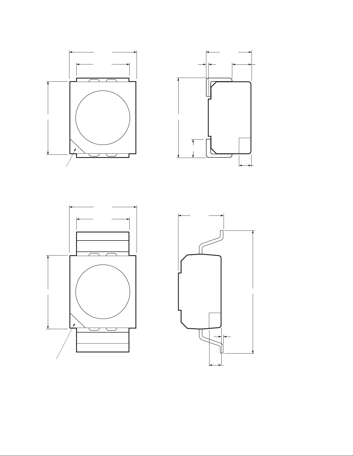
Package Dimensions
3.2 ± 0.2
2.8 ± 0.2
2.2 ± 0.2
CATHODE MARKING
(ANODE MARKING FOR AlGaAs DEVICES)
TOP MOUNT
2.8 ± 0.2
2.2 ± 0.2
1.9 ± 0.2
0.1 TYP. 0.8 ± 0.1
3.5 ± 0.2
0.8 ± 0.3
0.5 ± 0.1
1.9 ± 0.2
3.2 ± 0.2
CATHODE MARKING
REVERSE MOUNT
NOTE: ALL DIMENSIONS IN MILLIMETERS.
2
5.2 ± 0.2
0.1 TYP.
0.5 ± 0.1

Table 1. Device Selection Guide
Red
Part Number Min IV (mcd) Typ. IV (mcd) Max. IV (mcd) Test Current (mA) Dice Technology
HSMS-A100-J00J1 4.50 15.00 - 20 GaP
HSMS-A100-L00J1 11.20 15.00 - 20 GaP
HSMS-A100-H70J2 3.55 - 7.20 10 GaP
HSMS-A100-J80J2 5.60 - 14.00 10 GaP
HSMH-A100-L00J1 11.20 15.00 - 20 AlGaAs
HSMH-A100-N00J1 28.50 50.00 - 20 AlGaAs
HSMH-A100-M80J2 22.40 - 56.00 10 AlGaAs
HSMC-A100-Q00J1 71.50 100.00 - 20 AlInGaP
HSMC-A100-R00J1 112.50 140.00 - 20 AlInGaP
HSMC-A101-S00J1 180.00 220.00 - 20 AlInGaP
HSMZ-A100-T00J1 285.00 350.00 - 20 AlInGaP
HSMC-A100-P30J1 45.00 - 90.00 20 AlInGaP
Red Orange
Part Number Min IV (mcd) Typ. IV (mcd) Max. IV (mcd) Test Current (mA) Dice Technology
HSMJ-A100-Q00J1 71.50 100.00 - 20 AlInGaP
HSMJ-A101-S00J1 180.00 200.00 - 20 AlInGaP
HSMV-A100-T00J1 285.00 350.00 - 20 AlInGaP
HSMJ-A100-R40J1 112.50 - 285.00 20 AlInGaP
HSMV-A100-S80J1 224.00 - 560.00 20 AlInGaP
Orange
Part Number Min IV (mcd) Typ. IV (mcd) Max. IV (mcd) Test Current (mA) Dice Technology
HSMD-A100-J00J1 4.50 15.00 - 20 GaP
HSMD-A100-L00J1 11.20 15.00 - 20 GaP
HSMD-A100-K4PJ2 7.20 - 18.00 10 GaP
HSML-A100-Q00J1 71.50 100.00 - 20 AlInGaP
HSML-A101-S00J1 180.00 220.00 - 20 AlInGaP
3

Yellow / Amber
Part Number Min IV (mcd) Typ. IV (mcd) Max. IV (mcd) Test Current (mA) Dice Technology
HSMY-A100-J00J1 4.50 12.00 - 20 GaP
HSMY-A100-L00J1 11.20 12.00 - 20 GaP
HSMY-A100-J35J2 4.50 - 9.00 10 GaP
HSMA-A100-Q00J1 71.50 100.00 - 20 AlInGaP
HSMA-A101-S00J1 180.00 220.00 - 20 AlInGaP
HSMU-A100-S00J1 180.00 320.00 - 20 AlInGaP
HSMA-A101-R8WJ1 140.00 - 355.00 20 AlInGaP
HSMU-A100-S4WJ1 180.00 - 450.00 20 AlInGaP
Yellow Green
Part Number Min IV (mcd) Typ. IV (mcd) Max. IV (mcd) Test Current (mA) Dice Technology
HSMG-A100-J02J1 4.50 18.00 - 20 GaP
HSMG-A100-K72J2 9.00 - 18.00 10 GaP
HSME-A100-M02J1 18.00 70.00 - 20 AlInGaP
HSME-A100-N82J1 35.50 - 90.00 20 AlInGaP
Emerald Green
Part Number Min IV (mcd) Typ. IV (mcd) Max. IV (mcd) Test Current (mA) Dice Technology
HSMG-A100-H01J1 2.80 8.00 - 20 GaP
HSMG-A100-H41J2 2.80 - 7.20 10 GaP
HSME-A100-L01J1 11.20 40.00 - 20 AlInGaP
HSME-A100-M3PJ1 18.00 - 35.50 20 AlInGaP
Green
Part Number Min IV (mcd) Typ. IV (mcd) Max. IV (mcd) Test Current (mA) Dice Technology
HSMM-A101-R00J1 112.50 200.00 - 20 InGaN
HSMM-A100-S00J1 180.00 350.00 - 20 InGaN
HSMM-A100-U4PJ1 450.00 - 1125.00 20 InGaN
Blue
Part Number Min IV (mcd) Typ. IV (mcd) Max. IV (mcd) Test Current (mA) Dice Technology
HSMN-A101-N00J1 28.50 50.00 - 20 InGaN
HSMN-A100-P00J1 45.00 70.00 - 20 InGaN
HSMN-A100-R4YJ1 112.50 - 285.00 20 InGaN
Notes:
1. The luminous intensity IV, is measured at the mechanical axis of the lamp package. The actual peak of the spatial radiation pattern may not
be aligned with this axis.
2. IV Tolerance = ±12%
4

Part Numbering System
HSM x
- A x2 x3x4 - x5x6 x7 x8x
1
9
Packaging Option
Color Bin Selection
Intensity Bin Select
Device Specic Conguration
Package Type
LED Chip Color
Absolute Maximum Ratings (TA = 25°C)
Parameters HSMS/D/Y/G HSMH HSMC/J/L/A HSME HSMZ/V/U HSMM/K/B/N
DC Forward Current
Peak Forward Current
[1]
30 mA 30 mA 30 mA
[2]
100 mA 100 mA 100 mA 100 mA 100 mA 100 mA
Power Dissipation 63 mW 60 mW 63 mW 48 mW 72 mW 114 mW
Reverse Voltage 5 V
Junction Temperature 110°C
Operating Temperature –55°C to +100°C
Storage Temperature –55°C to +100°C
Notes:
1. Derate linearly as shown in Figure 4.
2. Duty factor = 10%, Frequency = 1 kHz.
3. Drive current between 10 mA and 30 mA is recommended for best long term performance.
4. Operation at current below 5 mA is not recommended.
[3,4]
20 mA
[4]
30 mA
[3,4]
30 mA
5

Optical Characteristics (TA = 25˚C)
Viewing Luminous
Peak Dominant Angle Luminous Intensity/
Wavelength Wavelength
Dice O
(nm) OD (nm) (Degrees) (lm/W) Iv(mcd)/)v(mlm)
PEAK
[1]
2 T
[2]
Ecacy K
1/2
[3]
Total Flux
v
Color Part Number Technology Typ. Typ. Typ. Typ. Typ.
Red HSMS-A100 GaP 635 626 120 120 0.45
HSMH-A100 AlGaAs 645 637 120 63 0.45
HSMC-A10x AlInGaP 635 626 120 150 0.45
HSMZ-A100 AlInGaP 639 630 120 155 0.45
Red HSMJ-A10x AlInGaP 621 615 120 240 0.45
Orange
HSMV-A100 AlInGaP 623 617 120 263 0.45
Orange HSMD-A100 GaP 600 602 120 380 0.45
HSML-A10x AlInGaP 609 605 120 320 0.45
Amber HSMY-A100 GaP 583 585 120 520 0.45
HSMA-A10x AlInGaP 592 590 120 480 0.45
HSMU-A100 AlInGaP 594 592 120 500 0.45
Yellow HSMG-A100 GaP 565 569 120 590 0.45
Green
HSME-A100 AlInGaP 575 570 120 560 0.45
Emerald HSMG-A100 GaP 558 560 120 650 0.45
Green
HSME-A100 AlInGaP 566 560 120 610 0.45
Green HSMM-A10x InGaN 523 525 120 500 0.45
Cyan HSMK-A10x InGaN 502 505 120 300 0.45
Blue HSMB-A100 GaN 428 462 120 65 0.45
HSMN-A10x InGaN 468 470 120 75 0.45
Notes:
1. The dominant wavelength, OD, is derived from the CIE Chromaticity Diagram and represents the color of the device.
2. T
is the o-axis angle where the luminous intensity is 1/2 the peak intensity.
1/2
3. Radiant intensity, Ie in watts/steradian, may be calculated from the equation Ie = Iv/Kv, where Iv is the luminous intensity in candelas and Kv is
the luminous ecacy in lumens/watt.
Electrical Characteristics (TA = 25˚C)
Forward Voltage Reverse Voltage Reverse Voltage Thermal
V
Part Number Typ. Max. Min. Min. RT
HSMS/D/Y/G 2.2 2.6 5 — 180
HSMH 1.9 2.6 5 — 180
HSMC/J/L/A/E 1.9 2.4 5 — 280
HSMZ/V/U 2.2 2.6 5 — 280
HSMB 3.9 4.3 — 5 280
HSMM/K/N 3.4 4.05 — 5 280
(Volts) @ IF = 20 mA VR @ 100 μA VR @ 10 μA Resistance
F
(°C/W)
JP
6

1.0
BLUE
0.9
CYAN
0.8
GREEN
0.7
0.6
0.5
0.4
0.3
RELATIVE INTENSITY
0.2
0.1
0
380 480 580 680 730 780
WAVELENGTH – nm
630530430
EMERALD GREEN
YELLOW GREEN
AMBER
ORANGE
RED ORANGE
RED
35
30
HSMS/D/Y/G
HSMZ/V/U
25
20
15
10
FORWARD CURRENT – mA
HSMH
HSMC/J/L/A/E
5
0
12 4
03
HSMM/K/N
HSMB
FORWARD VOLTAGE – V
Figure 2. Forward current vs. forward voltage.
5
1.0
0.8
0.6
0.4
RELATIVE INTENSITY
0.2
0
380 480 580 680 730 780
GaP
EMERALD
GREEN
GaP
YELLOW
GREEN
GaN BLUE
GaP YELLOW
GaP ORANGE
GaP RED
630530430
WAVELENGTH – nm
Figure 1. Relative intensity vs. wavelength.
35
30
HSMS/D/G/
Y/H/Z/V/U
25
20
15
CURRENT - mA
10
HSMC/J/L/A
HSME
HSMM/K/B/N
5
0
0 20 40 60 80 100 120
TEMPERATURE (°C)
35
30
25
20
HSME
15
CURRENT - mA
10
5
0
0 20 40 60 80 100 120
HSMS/D/G/Y/H
HSMC/J/L/A
HSMZ/V/U
HSMM/K/N
HSMB
TEMPERATURE (°C)
1.8
1.6
1.4
1.2
1.0
0.8
0.6
0.4
(NORMALIZED AT 20 mA)
RELATIVE LUMINOUS INTENSITY
0.2
0
515 30
020
10
DC FORWARD CURRENT – mA
AlInGaP
AlGaAs
Gap
InGaN
GaN
25
Figure 3. Relative intensity vs. forward current.
540
530
520
510
500
490
480
470
DOMINANT WAVELENGTH – nm
460
020
515 30
10
CURRENT – mA
GREEN
CYAN
BLUE
25
35
35
Figure 4. Maximum forward current vs. ambient
temperature. Derated based on T
MAX = 110˚C,
J
RθJA = 500˚C/W.
7
Figure 4b. Maximum Forward Current Vs. Solder
Point Temperature. Derated based on T
MAX =
J
110°C, RθJP = 180°C/W or 280°C/W.
Figure 5. Dominant wavelength vs. forward
current – InGaN devices.

(
)
0.5
0.4
0.3
0.2
0.1
GaP/AlGaAs/
0
(NORMALIZED AT 25°C)
AlInGaP
F
-0.1
DELTA V
-0.2
-0.3
-100
TEMPERATURE – °C
InGaN/GaN
0 100
1.0
0.8
0.6
0.4
NORMALIZED INTENSITY
0.2
0
15050-50
-70 -50
-30 0 20 30 50 70 90-90 -20-80 -60 -40 -10 10 40 60 80
ANGULAR DISPLACEMENT – DEGREES
Figure 6. Forward voltage shift vs. temperature.
20 SEC. MAX.
240 C MAX.
100-150 C
TEMPERATURE
3 C/SEC. MAX.
3 C/SEC.
MAX.
120 SEC. MAX.
60-150 SEC.
TIME
183 C
–6 C/SEC.
MAX.
Figure 7. Radiation Pattern.
Figure 8a. Recommended SnPb reow soldering prole.
Note: For detail information on reow soldering of Avago surface
mount LEDs, do refer to Avago Application Note AN 1060 Surface
Mounting SMT LED Indicator Components.
250
TURBULENT WAVE
LAMINAR WAVE
HOT AIR KNIFE
10 to 30 SEC.
255 - 260 C
3 C/SEC. MAX.
3 C/SEC. MAX.
60 - 120 SEC.
6 C/SEC. MAX.
100 SEC. MAX.
TEMPERATURE
217 C
200 C
150 C
TIME
Acc. to J-STD-020C
Figure 8b. Recommended Pb-free reow soldering prole.
4.50
1.50
2.60
200
150
FLUXING
100
TEMPERATURE – C
50
30
01020
CONVEYOR SPEED = 1.83 M/MIN (6 FT/MIN)
PREHEAT SETTING = 150C (100C PCB)
SOLDER WAVE TEMPERATURE = 245C
AIR KNIFE AIR TEMPERATURE = 390C
AIR KNIFE DISTANCE = 1.91 mm (0.25 IN.)
AIR KNIFE ANGLE = 40
LEADED SOLDER: SN63; FLUX: RMA
LEAD-FREE SOLDER: 96.5 wt% SN, 3 wt% Ag, 0.5 wt% Cu
NOTE: ALLOW FOR BOARDS TO BE SUFFICIENTLY COOLED
BEFORE EXERTING MECHANICAL FORCE.
PREHEAT
30 40 50
60 70 80 90 100
TIME – SECONDS
Figure 9. Recommended wave soldering prole.
8
BOTTOM SIDE
OF PC BOARD
TOP SIDE OF
PC BOARD
Figure 10. Recommended soldering pad pattern.

TRAILER COMPONENT LEADER
200 mm MIN. FOR Ø180 REEL.
200 mm MIN. FOR
Ø330 REEL.
Figure 11. Tape leader and trailer dimensions.
480 mm MIN. FOR
960 mm MIN. FOR
USER FEED DIRECTION
Ø180 REEL.
Ø330 REEL.
C
A
+0.1
Ø 1.5
–0
3.05 ± 0.1
Figure 12. Tape dimensions.
4 ± 0.1 4 ± 0.1 2 ± 0.05
+0.1
Ø1
–0
1.75 ± 0.1
3.5 ± 0.05
8°
2.29 ± 0.1
C
+0.3
8
–0.1
3.81 ± 0.1
A
0.229 ± 0.01
9

180
2
+0.5
–0
Ø 20.5 ± 0.3
Ø 13 ± 0.2
+0
62.5
–2.5
+1.50
8.4 (MEASURED AT OUTER EDGE)
–0.00
14.4 (MAX. MEASURED AT HUB)
LABEL AREA (111 mm x 57 mm)
WITH DEPRESSION (0.25 mm)
Figure 13. Reel dimensions.
PRINTED LABEL
Figure 14. Reeling orientation.
USER FEED DIRECTION
CATHODE SIDE
7.9 (MIN.)
10.9 (MAX.)
10

Intensity Bin Select (X5X6)
Individual reel will contain parts
from one half bin only.
X
Min Iv Bin
5
X
6
0 Full Distribution
2 2 half bins starting from X
3 3 half bins starting from X
4 4 half bins starting from X
5 5 half bins starting from X
6 2 half bins starting from X
7 3 half bins starting from X
8 4 half bins starting from X
9 5 half bins starting from X
1
5
1
5
1
5
1
5
2
5
2
5
2
5
2
5
Intensity Bin Limits
Bin ID Min. (mcd) Max. (mcd)
G1 1.80 2.24
G2 2.24 2.80
H1 2.80 3.55
H2 3.55 4.50
J1 4.50 5.60
J2 5.60 7.20
K1 7.20 9.00
K2 9.00 11.20
L1 11.20 14.00
L2 14.00 18.00
M1 18.00 22.40
M2 22.40 28.50
N1 28.50 35.50
N2 35.50 45.00
P1 45.00 56.00
P2 56.00 71.50
Q1 71.50 90.00
Q2 90.00 112.50
R1 112.50 140.00
R2 140.00 180.00
S1 180.00 224.00
S2 224.00 285.00
T1 285.00 355.00
T2 355.00 450.00
U1 450.00 560.00
U2 560.00 715.00
V1 715.00 900.00
V2 900.00 1125.00
Tolerance of each bin limit = ± 12%
Color Bin Select (X7)
Individual reel will contain parts
from one full bin only.
X
7
0 Full Distribution
Z A and B only
Y B and C only
W C and D only
V D and E only
U E and F only
T F and G only
S G and H only
Q A, B, and C only
P B, C, and D only
N C, D, and E only
M D, E, and F only
L E, F, and G only
K F, G, and H only
1 A, B, C, and D only
2 E, F, G, and H only
3 B, C, D, and E only
4 C, D, E, and F only
5 A, B, C, D, and E only
6 B, C, D, E, and F only
Color Bin Limits
Blue Min. (nm) Max. (nm)
A 460.0 465.0
B 465.0 470.0
C 470.0 475.0
D 475.0 480.0
Cyan Min. (nm) Max. (nm)
A 490.0 495.0
B 495.0 500.0
C 500.0 505.0
D 505.0 510.0
Green Min. (nm) Max. (nm)
A 515.0 520.0
B 520.0 525.0
C 525.0 530.0
D 530.0 535.0
Color Bin Limits
Emerald
Green Min. (nm) Max. (nm)
A 552.5 555.5
B 555.5 558.5
C 558.5 561.5
D 561.5 564.5
Yellow
Green Min. (nm) Max. (nm)
E 564.5 567.5
F 567.5 570.5
G 570.5 573.5
H 573.5 576.5
Amber Min. (nm) Max. (nm)
A 582.0 584.5
B 584.5 587.0
C 587.0 589.5
D 589.5 592.0
E 592.0 594.5
F 594.5 597.0
Orange Min. (nm) Max. (nm)
A 597.0 600.0
B 600.0 603.0
C 603.0 606.0
D 606.0 609.0
E 609.0 612.0
Red Orange Min. (nm) Max. (nm)
A 611.0 616.0
B 616.0 620.0
Red Min. (nm) Max. (nm)
Full Distribution
Tolerance of each bin limit = ± 1 nm.
11

Packaging Option (X8X9)
Option Test Current Package Type Reel Size
J1 20 mA Top Mount 7 inch
J4 20 mA Top Mount 13 inch
H1 20 mA Reverse Mount 7 inch
H4 20 mA Reverse Mount 13 inch
J2 10 mA Top Mount 7 inch
J5 10 mA Top Mount 13 inch
H2 10 mA Reverse Mount 7 inch
H5 10 mA Reverse Mount 13 inch
Moisture Sensitivity
This product is qualied as Moisture Sensitive Level 2a
per Jedec J-STD-020. Precautions when handling this
moisture sensitive product is important to ensure the
reliability of the product. Do refer to Avago Application
Note AN5305 Handling of Moisture Sensitive Surface
Mount Devices for details.
A. Storage before use
- Unopen moisture barrier bag (MBB) can be stored
at <40°C/90%RH for 12 months. If the actual shelf
life has exceeded 12 months and the HIC indicates
that baking is not required, then it is safe to reow
the LEDs per the original MSL rating.
- It is not recommended to open the MBB prior to
assembly (e.g. for IQC).
B. Control after opening the MBB
- The humidity indicator card (HIC) shall be read immediately upon opening of MBB.
- The LEDs must be kept at <30°C / 60%RH at all time
and all high temperature related process including
soldering, curing or rework need to be completed
within 672 hours.
C. Control for unnished reel
- For any unuse LEDs, they need to be stored
in sealed MBB with desiccant or desiccator at
<5%RH.
D. Control of assembled boards
- If the PCB soldered with the LEDs is to be subjected
to other high temperature processes, the PCB need
to be stored in sealed MBB with desiccant or desiccator at <5%RH to ensure no LEDs have exceeded
their oor life of 672 hours.
E. Baking is required if:
- “10%” is Not blue and “5%” HIC indicator turns
pink.
- The LEDs are exposed to condition of >30°C / 60%
RH at any time.
- The LEDs oor life exceeded 672 hours.
Recommended baking condition: 60±5°C for 20 hours.
For product information and a complete list of distributors, please go to our website: www.avagotech.com
Avago, Avago Technologies, and the A logo are trademarks of Avago Technologies in the United States and other countries.
Data subject to change. Copyright © 2005-2010 Avago Technologies. All rights reserved. Obsoletes AV01-0040EN
AV02-0198EN - May 6, 2010
 Loading...