


HSMW-A10x-xxxxx
White Surface Mount LED Indicator
SMT PLCC-2
Data Sheet
Description
This family of SMT LEDs is packaged in the industry standard PLCC-2 package. These SMT LEDs have high reliability performance and are designed to work under a wide
range of environmental conditions. This high reliability feature makes them ideally suited to be used under
harsh interior automotive as well as interior signs application conditions.
To facilitate easy pick & place assembly, the LEDs are
packed in EIA-compliant tape and reel. Every reel will be
shipped in single intensity and color bin.
These LEDs are compatible with IR solder reflow process.
The wide viewing angle at 120° makes these LEDs ideally suited for panel, push button, or general backlighting in automotive interior, office quipment, industrial equipment, and home appliances. The flat top
emitting surface makes it easy for these LEDs to mate
with light pipes. With the built-in reflector pushing up
the intensity of the light output, these LEDs are also suitable to be used as LED pixels in interior electronic signs.
The super high brightness white PLCC-2 SMT LED is
ideal for all kinds of backlighting applications in interior automotive, office automation, electrical appliance
and industrial instrument markets to offer a clear and
attractive product differentiation. The wide viewing
angle at 120˚also enables this white PLCC-2 SMT LED
to be used in localised area ambience lighting in applications such as vanity mirror light, cabin light, and
car door puddle light. The white color backlighting offered by this series of white PLCC-2 SMT LED is suitable to backlight color LCD screen in applications such
as GPS (global positioning system) screens in cars.
Features
x Industry standard PLCC-2 package
(plastic leaded chip carrier)
x High reliability LED package with silicone
encapsulation
x Tight white color binning
x Wide viewing angle at 120˚
x Available in 8 mm carrier tape on 7-inch reel
(2000 pieces)
x Compatible with Reflow and TTW soldering process
Applications
x Interior automotive
– Instrument panel backlighting
– Central console backlighting
– Cabin backlighting
x Office automation, home appliances, industrial
equipment
– Front panel backlighting
– Push button backlighting
– Display backlighting
CAUTION: HSMW-A10x LEDs are Class 2 ESD sensitive. Please observe appropriate precautions during
handling and processing. Refer to Avago Technologies Application Note AN-1142 for additional details.

Package Dimensions
3.2 ± 0.2
2.8 ± 0.2
2.2 ± 0.2
CATHODE MARKING
(ANODE MARKING FOR AlGaAs DEVICES)
TOP MOUNT
2.8 ± 0.2
1.9 ± 0.2
0.1 TYP. 0.8 ± 0.
3.5 ± 0.2
0.8 ± 0.3
0.5 ± 0.1
3.2 ± 0.2
CATHODE MARKING
2.2 ± 0.2
REVERSE MOUNT
1.9 ± 0.2
5.2 ± 0.2
0.1 TYP.
0.5 ± 0.1
2

Device Selection Guide
Color Part Number Min. IV (mcd) Typ. IV (mcd) Max. IV (mcd) Test Current (mA) Dice Technology
White HSMW-A100-U40H1 450.0 - 1125.0 20 InGaN
HSMW-A100-U40J1 450.0 - 1125.0 20 InGaN
Notes:
1. The luminous intensity IV, is measured at the mechanical axis of the lamp package. The actual peak of the spatial radiation pattern may not be
aligned with this axis.
2. IV tolerance = ±12 %.
Part Numbering System
HSM x1 –A x2 x3x4 - x5x6 x7 x8x
9
Packaging 0ption
Color Bin Selection
Intensity Bin Select
Device Specific Configuration
Package Type
LED Chip Color
Absolute Maximum Ratings (TA = 25°C)
Parameters HSMW
DC Forward Current
Peak Forward Current
Power Dissipation 114 mW
Reverse Voltage 5 V
Junction Temperature 110°C
Operating Temperature –40°C to +100°C
Storage Temperature –40°C to +100°C
Notes:
1. Derate linearly as shown in Figure 4.
2. Duty factor = 10%, frequency = 1 kHz.
[1]
30 mA
[2]
90 mA
3

Optical Characteristics (TA = 25°C)
Viewing Angle Luminous Total Flux/
Typ. Chromaticity 2T
Dice Coordinates
[1]
(Degrees) (lm/W) )V (lm) /IV (mcd)
Color Part Number Technology x y Typ. Typ. Typ.
White HSMW-A100 InGaN 0.31 0.31 120 18 2.4
White HSMW-A101 InGaN 0.31 0.31 120 9 2.4
Notes:
1. The chromaticity coordinates are derived from the CIE 1931 Chromaticity Diagram and represent the perceived color of the device.
2. T
is the off-axis angle where the luminous intensity is 1/2 the peak intensity.
1/2
[2]
Efficiency, Ke Luminous Intensity
1/2
Electrical Characteristics (TA = 25°C)
Part Forward Voltage, VF (Volts) @ IF = 20 mA Reverse Voltage, VR @ 10 μA Thermal Resistance
Number Typ. Max. Min. RTJP (°C/W)
HSMW 3.4 4.05 5 280
35
30
25
20
15
10
FORWARD CURRENT - mA
5
0
0 3.0
1.0 2.0 3.50.5 1.5 2.5 4.0
FORWARD VOLTAGE - V
Figure 1. Forward Current vs. forward voltage
0.020
0.015
0.010
0.005
Y-COORDINATES
-0.005
-0.010
0
30 mA
-0.002 00.001 0.003
-0.003
20 mA
-0.001
X-COORDINATES
Figure 3. Chromaticity shift vs. currrent.
Note: (x,y) values @ 20 mA reference to (0.0)
10 mA
5 mA
0.002
1.6
1.4
1.2
1.0
0.8
0.6
(NORMALIZED AT 20 mA)
0.4
RELATIVE LUMINOUS INTENSITY
0.2
0
02 0
10
DC FORWARD CURRENT - mA
2551 5 3 0
Figure 2. Relative intensity vs. forward current.
35
30
25
20
15
CURRENT - mA
10
5
0
0
40
20 60 80 120
TEMPERATURE - °C
100
Figure 4. Maximum forward current vs. ambient temperature.
Derated based on T
MAX = 110°C, RTJA = 500°C/W.
J
35
4

1.0
0.8
0.6
D
0.4
NORMALIZED INTENSITY
0.2
0
-70 -50
Figure 5. Radiation pattern
20 SEC. MAX.
240°C MAX.
3°C/SEC. MAX.
100-150°C
TEMPERATURE
3°C/SEC.
MAX.
120 SEC. MAX.
-30020 30 507 0 90-90 -20-80 -60 -40 -10 10 40 60 80
ANGULAR DISPLACEMENT - DEGREES
183°C
-6 °C/SEC.
MAX.
60-150 SEC.
TIME
Figure 6. Recommended Pick and Place Nozzle Size
+5 °C
255 °C
217 °C
3 °C/SEC. MAX.
125 °C ± 25 °C
TEMPERATURE
* THE TIME FROM 25 °C TO PEAK TEMPERATURE = 6 MINUTES MAX.
MAX. 120 SEC.
-0 °C
Note: Diameter "D" should
be smaller than 2.2mm
10 to 20 SEC.
6 °C/SEC. MAX.
60 to 150 SEC.
TIME
Figure 7a. Recommended SnPb reflow soldering profile Figure 7b. Recommended Pb-free reflow soldering profile
Note: For detail information on reflow soldering of Avago surface mount LEDs, do refer to Avago Application Note AN 1060 Surface Mounting SMT
LED Indicator Components.
4.50
1.50
250
200
°C
150
TURBULENT WAVE LAMINAR WAVE
BOTTOM SIDE
HOT AIR KNIFE
OF PC BOARD
TOP SIDE
OF PC BOARD
2.60
FLUXING
100
TEMPERATURE -
50
30
0
0 6 0
PREHEAT
20 40 7010 30 50 80 90 100
TIME - SECONDS
CONVEYOR SPEED = 1.83 M/MIN (6 FT/MIN)
PREHEAT SETTING = 150°C (100°C PCB)
SOLDER WAVE TEMPERATURE = 245°C
AIR KNIFE TEMPERATURE = 390°C
AIR KNIFE DISTANCE = 1.91 mm (0.25 IN.)
AIR KNIFE ANGLE = 40°
SOLDER: SN63; FLUX: RMA
NOTE: ALLOW FOR BOARDS TO BE SUFFICIENTLY
COOLED BEFORE EXERTING MECHANICAL FORCE.
SOLDER RESIST
Figure 8. Recommended wave soldering profile Figure 9. Recommended soldering pad pattern
5
TRAILER COMPONENT LEADER
(
)
200 mm MIN. FOR 180 REEL.
200 mm MIN. FOR 330 REEL.
Figure 10. Tape leader and trailer dimension
480 mm MIN. FOR 180 REEL.
960 mm MIN. FOR 330 REEL.
C
A
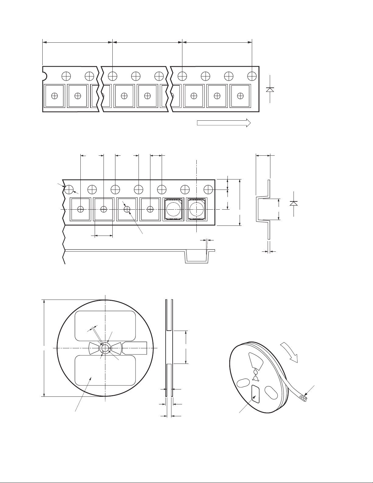
USER FEED DIRECTION
+0.1
1.5
-0
3.05 ± 0.1
Figure 11. Tape dimension
+0.5
2
- 0
180
4 ± 0.1 4 ± 0.1 2 ± 0.05
+0.1
1
- 0
∅
20.5 ± 0.3
62.5
+0
- 2.5
8°
1.75 ± 0.1
3.5 ± 0.05
8
+0.3
- 0.1
2.29 ± 0.1
C
3.81 ± 0.1
A
0.229 ± 0.01
USER FEED DIRECTION
LABEL AREA (111 mm x 57 mm)
WITH DEPRESSION
Figure 12. Reel dimensions
6
∅
13 ± 0.2
0.25 mm
+1.50
8.4 *
- 0.00
14.4 **
7.9 (MIN.)
10.9 (MAX.)
CATHODE SIDE
PRINTED LABEL
Figure 13. Reeling orientation

Moisture Sensitivity
This product is qualified as Moisture Sensitive Level 2a
per Jedec J-STD-020. Precautions when handling this
moisture sensitive product is important to ensure the
reliability of the product. Do refer to Avago Application
Note AN5305 Handling of Moisture Sensitive Surface
Mount Devices for details.
A. Storage before use
- Unopen moisture barrier bag (MBB) can be stored
at <40°C/90%RH for 12 months. If the actual shelf
life has exceeded 12 months and the HIC indicates
that baking is not required, then it is safe to reflow
the LEDs per the original MSL rating.
- It is not recommended to open the MBB prior to
assembly (e.g. for IQC).
B. Control after opening the MBB
- The humidity indicator card (HIC) shall be read
immediately upon opening of MBB.
- The LEDs must be kept at <30°C / 60%RH at all time
and all high temperature related process including
soldering, curing or rework need to be completed
within 672 hours.
C. Control for unfinished reel
- For any unuse LEDs, they need to be stored in
sealed MBB with desiccant or desiccator at <5%RH.
D. Control of assembled boards
- If the PCB soldered with the LEDs is to be subjected
to other high temperature processes, the PCB
need to be stored in sealed MBB with desiccant
or desiccator at <5%RH to ensure no LEDs have
exceeded their floor life of 672 hours.
E. Baking is required if:
- “10%” or “15%” HIC indicator turns pink.
- The LEDs are exposed to condition of >30°C / 60%
RH at any time.
- The LEDs floor life exceeded 672 hours.
Recommended baking condition: 60±5°C for 20 hours.
Handling Precaution
The encapsulation material of the product is made of
sili cone for better reliability of the product. As silicone
is a soft material, please do not press on the silicone or
poke a sharp object onto the silicone. These might damage the product and cause premature failure. During assembly of handling, the unit should be held on the body
only. Please refer to Avago Application Note AN 5288 for
detail information.
Intensity Bin Select (X5X6)
Individual reel will contain parts
from one half bin only.
X
Min Iv Bin
5
X
6
0 Full Distribution
3 3 half bins starting from X
4 4 half bins starting from X
5 5 half bins starting from X
7 3 half bins starting from X
8 4 half bins starting from X
9 5 half bins starting from X
1
5
1
5
1
5
2
5
2
5
2
5
Intensity Bin Limits
Bin ID Min. (mcd) Max. (mcd)
Q1 71.50 90.00
Q2 90.00 112.50
R1 112.50 140.00
R2 140.00 180.00
S1 180.00 224.00
S2 224.00 285.00
T1 285.00 355.00
T2 355.00 450.00
U1 450.00 560.00
U2 560.00 715.00
V1 715.00 900.00
V2 900.00 1125.00
Tolerance of each bin limit = ± 12%.
7

Color Bin Limits
Bin ID Limits (Chromaticity Coordinates)
A x 0.352 0.365 0.365 0.352
y 0.377 0.395 0.360 0.341
B x 0.340 0.352 0.352 0.340
y 0.360 0.377 0.341 0.325
C x 0.327 0.340 0.340 0.327
y 0.342 0.360 0.325 0.306
D x 0.315 0.327 0.327 0.315
y 0.325 0.342 0.306 0.290
E x 0.302 0.315 0.315 0.302
y 0.307 0.325 0.290 0.271
F x 0.290 0.302 0.302 0.290
y 0.290 0.307 0.271 0.255
Note: Tolerance for each bin limit = ± 0.02.
0.40
A
0.35
0.30
Y-COORDINATE
E
F
B
C
D
Color Bin Select (X7)
Individual reel will contain parts
from one full bin only.
X
7
0 Full Distribution
Z A and B only
Y B and C only
W C and D only
V D and E only
U E and F only
Q A, B and C only
P B, C and D only
N C, D and E only
M D, E and F only
1 A, B, C and D only
3 B, C, D and E only
4 C, D, E and F only
5 A, B, C, D and E only
6 B, C, D, E and F only
0.25
0.25
0.300.40
X-COORDINATE
0.35
Figure 14. Color Bins
Packaging Option (X8X9)
Option Test Current Package Type Reel Size
J1 20 mA Top Mount 7 inch
J2 10 mA Top Mount 7 inch
H1 20mA Reverse Mount 7 inch
For product information and a complete list of distributors, please go to our website: www.avagotech.com
Avago, Avago Technologies, and the A logo are trademarks of Avago Technologies in the United States and other countries.
Data subject to change. Copyright © 2005-2010 Avago Technologies. All rights reserved. Obsoletes AV01-0645EN
AV02-0490EN - January 20, 2010
 Loading...