

α
R
– ATTENUATION – dB/km
620
500
100
λ – WAVELENGTH – nm
660
300
400
680640 700
200
HFBR-RXXYYYZ Series (POF)
HFBR-EXXYYYZ Series (POF)
Plastic Optical Fiber Cable and Accessories
for Versatile Link
Data Sheet
Cable Description
The HFBR-R/EXXYYYZ series of plastic ber optic cables
are constructed of a single step-index ber sheathed
in a black polyethylene jacket. The duplex ber consists
of two simplex bers joined with a zipcord web.
Standard attenuation and extra low loss POF cables are
identical except for attenuation specications.
Polyethylene jackets on all plastic ber cables comply with UL VW-1 ame retardant specication (UL le
# E89328).
Cables are available in unconnectored or connectored
options. Refer to the Ordering Guide for part number
information.
Features
• Compatible with Avago Versatile Link Family of connectors and ber optic components
• 1 mm diameter Plastic Optical Fiber (POF) in two
grades: low cost standard POF with 0.22 dB/m typical
attenuation, or high performance extra low loss POF
with 0.19 dB/m typical attenuation
Applications
• Industrial data links for factory automation and plant
control
• Intra-system links; board-to-board, rack-to-rack
• Telecommunications switching systems
• Computer-to-peripheral data links, PC bus extension
• Proprietary LANs
• Digitized video
• Medical instruments
• Reduction of lightning and voltage transient suscep-
tibility
• High voltage isolation
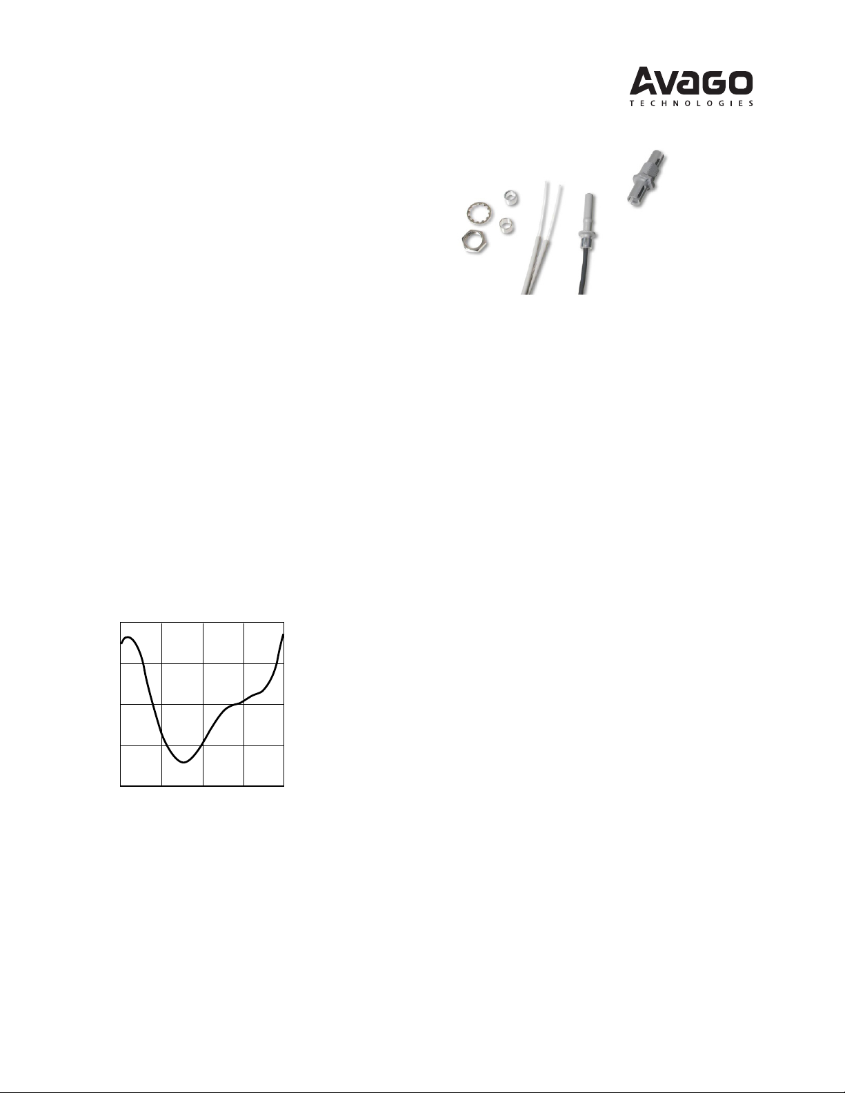
Figure 1. Typical POF attenuation vs. wavelength.
Plastic Optical Fiber Specications: HFBR-R/EXXYYYZ
Absolute Maximum Ratings
Parameter Symbol Min. Max. Unit Note
Storage and Operating Temperature T
Recommended Operating Temperature TO -40 +85 °C
Installation Temperature TI -20 +70 °C 1
Short Term Tensile Single Channel FT 50 N 2
Force
Dual Channel FT 100 N
Short Term Bend Radius r 25 mm 3, 4
Long Term Bend Radius r 35 mm
Long Term Tensile Load FT 1 N
Flexing 1000 Cycles 4
-55 +85 °C
S,O
Mechanical/Optical Characteristics, T
Parameter Symbol Min. Typ.
= -40 to +85°C unless otherwise specied.
A
[5]
Max. Unit Condition
Cable Standard Cable, αO 0.15 0.22 0.27 dB/m Source is HFBR-15XX
Attenuation Type "R" (660 mm LED, 0.5 NA)
Extra Low Loss, 0.15 0.19 0.23 = 50 meters
Type "E"
Reference Standard Cable, αR 0.12 0.19 0.24 dB/m Source is 650 nm,
Attenuation Type "R" 0.5 NA monochrometer,
Extra Low Loss, 0.12 0.16 0.19 = 50 meters
Type "E" Note 7, Figure 1
Numerical Aperture NA 0.46 0.47 0.50 >2 meters
Diameter, Core and Cladding DC 0.94 1.00 1.06 mm
Diameter, Jacket DJ 2.13 2.20 2.27 mm Simplex Cable
Propagation Delay Constant l/v 5.0 ns/m Note 6
Mass per Unit Length/Channel 5.3 g/m Without Connectors
Cable Leakage Current IL 12 nA 50 kV, = 0.3 meters
Refractive Index Core n 1.492
Cladding 1.417
Notes:
1. Installation temperature is the range over which the cable can be bent and pulled without damage. Below -20°C the cable becomes brittle
and should not be subjected to mechanical stress.
2. Short Term Tensile Force is for less than 30 minutes.
3. Short Term Bend Radius is for less than 1 hour nonoperating.
4. 90° bend on 25 mm radius mandrel. Bend radius is the radius of the mandrel around which the cable is bent.
5. Typical data are at 25°C.
6. Propagation delay constant is the reciprocal of the group velocity for propagation delay of optical power. Group velocity is v=c/n where c is
the velocity of light in free space (3xl08 m/s) and n is the eective core index of refraction.
7. Note that αR rises at the rate of about 0.0067 dB/°C, where the thermal rise refers to the LED temperature changes above 25°C. Please refer to
Figure 1 which shows the typical plastic optical ber attenuation versus wavelength at 25°C.
2
Plastic Fiber Connector Styles
Connector Description
Four connector styles are available for termination of plastic
optical ber: simplex, simplex latching, duplex and duplex
latching. All connectors provide a snap-in action when
mated to Versatile Link components. Simplex connectors
are color coded to facilitate identication of transmitter
and receiver connections. Duplex connectors are keyed
so that proper orientation is ensured during insertion. If
the POF cable/connector will be used at extreme operating temperatures or experience frequent and wide temperature cycling eects, the cable/connector attachment
can be strengthened with an RTV adhesive (see Plastic
Connectoring Instructions for more detail). The connectors
are made of a ame retardant VALOX UL94 V-0 material
(UL le # E121562).
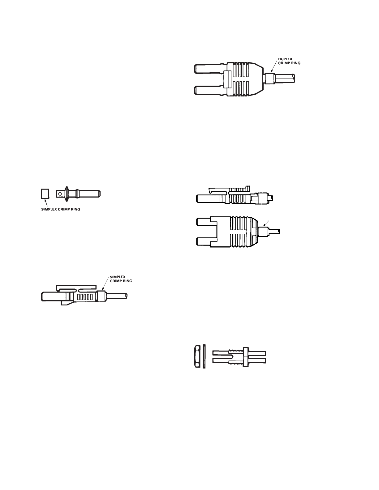
DUPLEX CONNECTOR STYLES
HFBR-4506Z – Duplex
HFBR-4526Z
Duplex connectors provide convenient duplex cable
termination and are keyed to prevent incorrect insertion
into duplex congured modules. The duplex connector is
compatible with dual combinations of horizontal or vertical
Versatile Link components (e.g., two horizontal transmitters, two vertical receivers, a horizontal transmitter with a
horizontal receiver, etc.). The duplex non-latching connector is available in parchment, o-white (HFBR-4506Z).
SIMPLEX CONNECTOR STYLES
HFBR-4501Z/4511Z – Simplex
, HFBR-4525Z
The simplex connector provides a quick and stable connection for applications that require a component-toconnector retention force of 8 Newtons (1.8 lb.). These
connectors are available in gray (HFBR-4501Z) or blue
(HFBR-4511Z).
HFBR-4503Z/4513Z – Simplex Latching
HFBR-4525Z
The simplex latching connector is designed for rugged
applications requiring a greater retention force — 80 Newtons ( 18 lb.) — than provided by a simplex nonlatching
connector. When inserting the simplex latching connector
into a module, the connector latch mechanism should be
aligned with the top surface of the horizontal modules,
or with the tall vertical side of the vertical modules. Misalignment of an inserted latching connector into either
module will not result in a positive latch. The connector is
released by depressing the rear section of the connector
lever, and then pulling the connector assembly away from
the module housing.
The simplex latching connector is available in gray (HFBR4503Z) or blue (HFBR-4513Z).
HFBR-4516Z – Duplex Latching
DUPLEX
CRIMP RING
HFBR-4526Z
The duplex latching connector is designed for rugged
applications requiring greater retention force than the
nonlatching duplex connector. When inserting the duplex
latching connector into a module, the connector latch
mechanism should be aligned with the top surface of the
dual combination of horizontal or vertical Versatile Link
components. The duplex latching connector is available
in gray (HFBR-4516Z).
Feedthrough/Splice
HFBR-4505Z/4515Z Bulkhead Adapter
The HFBR-4505Z/4515Z adapter mates two simplex
connectors for panel/bulkhead feedthrough of HFBR4501Z/4511Z terminated plastic ber cable. Maximum
panel thickness is 4.1 mm (0.16 inch). This adapter can
serve as a cable in-line splice using two simplex connectors. The adapters are available in gray (HFBR-4505Z) and
blue (HFBR-4515Z). This adapter is not compatible with
POF duplex, POF simplex latching, or HCS connectors.
3
 Loading...