

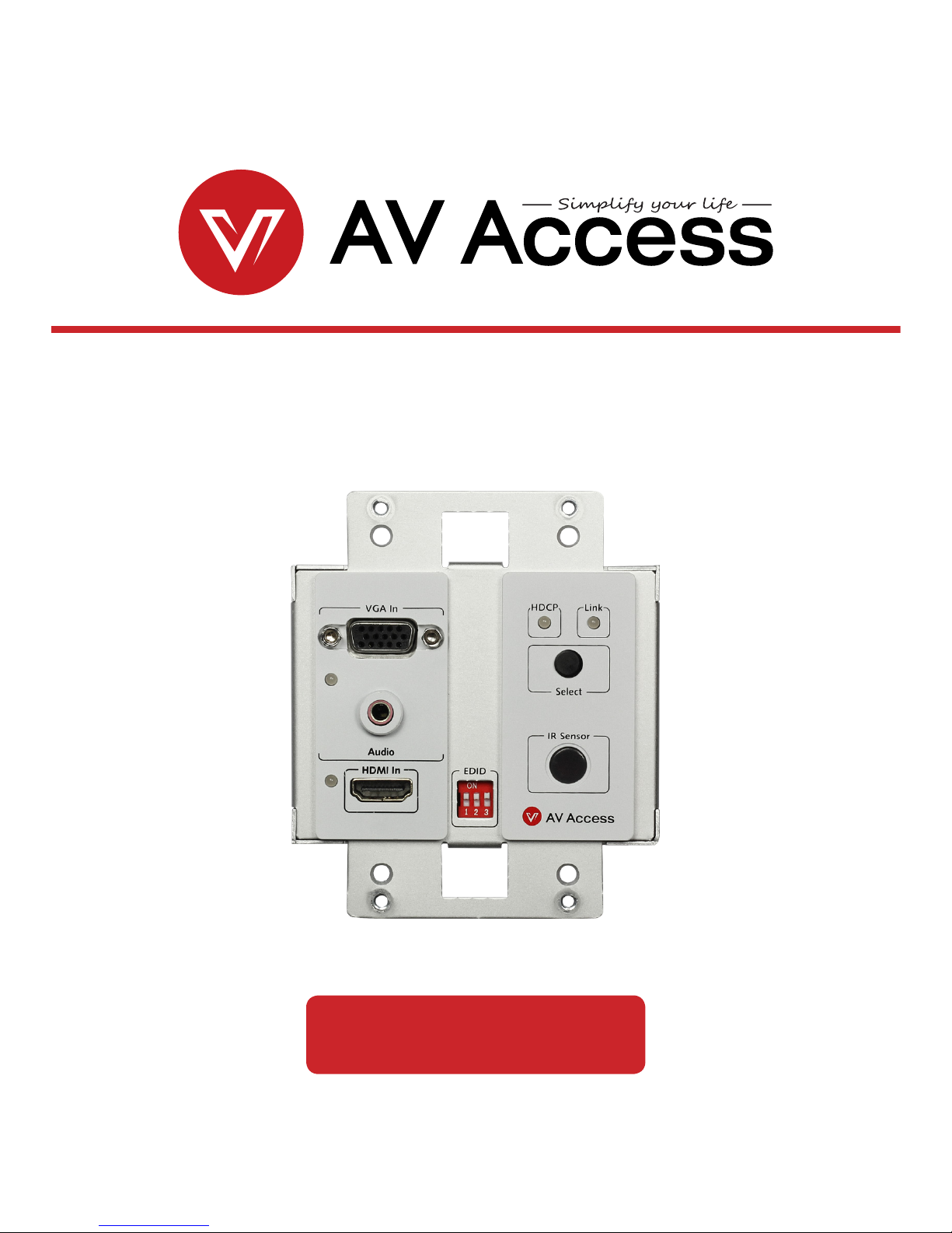
4KEX70-W
In Wall 4K HDBaseT Transmitter with HDMI/VGA
User Manual


Disclaimers
The information in this manual has been carefully checked and is believed to
be accurate. AV Access Technology Limited assumes no responsibility for any
infringements of patents or other rights of third parties which may result from its
use.
AV Access Technology Limited assumes no responsibility for any inaccuracies that
may be contained in this document. AV Access Technology Limited also makes
no commitment to update or to keep current the information contained in this
document.
AV Access Technology Limited reserves the right to make improvements to this
document and/or product at any time and without notice.
Trademarks Notice
All products or service names mentioned in this document may be trademarks of
the companies with which they are associated.
Contact Us
Business inquiry: services@avaccess.com
Technical problems: support@avaccess.com
Copyright
Copy, Reproduce, Distribute and/or Edit of this document or part of it as well
as utilization of its contents and communication thereof to others without
express authorization are prohibited. Offenders will be held liable for payment
of damages. All rights created by patent grant or registration of a utility model or
design patent are reserved. Copyright ©2017 AV Access Technology Limited All
rights reserved.

Important Safety Instructions
• Do not expose this device to rain, moisture, dripping or splashing. No objects
lled with liquids, such as vases, shall be placed on the device.
• Do not install or place this unit in a bookcase, built-in cabinet, or in another
conned space. Ensure the unit is well ventilated.
• To prevent risk of electric shock or fire hazard due to overheating, do not
obstruct the unit’s ventilation openings with newspapers, tablecloths,
curtains, or similar items.
• Do not install near any heat sources such as radiators, heat registers, stoves,
or other device (including ampliers) that produce heat.
• Do not place sources of naked ames, such as lighted candles, on the unit.
• Clean this device only with dry cloth.
• Unplug this device during lightning storms or when unused for long periods
of time.
• Protect the power cord from being walked on or pinched, particularly at
plugs.
• Only use attachments / accessories specied by the manufacturer.
• Refer all servicing to qualied service personnel.

www.avaccess.com
1
Table of Contents
Introduction .......................................................................................................... 2
Overview ...................................................................................................................................... 2
Features ........................................................................................................................................ 2
Package Contents ..................................................................................................................... 3
Panel .............................................................................................................................................. 4
Front Panel ........................................................................................................................... 4
Rear Panel ............................................................................................................................ 6
Installation Instructions ....................................................................................... 7
Input Source Switch .............................................................................................. 9
Automatic Switch .............................................................................................................. 9
Manual Button Switch ..................................................................................................... 9
EDID Management ............................................................................................. 10
Specication ....................................................................................................... 11
Trouble Shooting ................................................................................................ 13
Steps of Regular Troubleshooting Routine ............................................................ 13
Typical Questions ............................................................................................................14
Warranty .............................................................................................................. 17

www.avaccess.com
2
Introduction
Introduction
4KEX70-W is an in wall 4K HDBT transmitter which includes an HDMI input, a VGA
input and a HDBT output, and is designed to work with an HDBT receiver such as
the 4KEX70-RX-PSE. It supports resolutions up to 4K@60Hz 4:2:0 8bit and HDCP
for the HDMI signal. It can reliably extend the HDMI signals up to 131ft (40m) at 4K
and 230ft (70m) at 1080P over a CAT6a / 7 cable, or up to 115ft (35m) at 4K and
197ft (60m) at 1080P over a CAT5e / 6 cable.
This transmitter was developed to simplify the installation and create a clean
seamless look with your décor. It features one-way PoH function, allowing it to
receive power from an HDBT receiver with built-in PSE. It provides automatic and
manual button switch between the HDMI and VGA inputs. It also supports bi-
directional IR and RS-232 pass through.
4KEX70-W oers ideal solutions for homes, oces, digital entertainment centers,
control centers, conference rooms, schools and corporate training environments,
which require signal switching between VGA and HDMI sources and transmission
over long distances.
Overview

www.avaccess.com
3
Introduction
Before you start the installation of the product, please check the package contents
as below:
• HDBT Transmitter 4KEX70-W x1
• 3-Pin 3.5mm Phoenix Male Connector x1
• 2-Pin 3.5mm Phoenix Male Connector x2
• 2-Gang US Decora Wall Plate Cover with matching screws x1
• Flat Head Installation Screw (#6-32*20mm) x4
• User Manual x1
• Switches HDMI and VGA inputs to an HDBT output
• The HDMI input supports resolutions up to 4K@60Hz 4:2:0 8bit and HDCP
• Over a CAT6a / 7 cable, HDMI signal transmission distance up to 131ft at 4K
and 230ft at 1080P
• Over a CAT5e / 6 cable, HDMI signal transmission distance up to 115ft at 4K
and 197ft at 1080P
• EDID management
• Supports automatic and manual button switch between two inputs
• Supports one-way PoH, capable of receiving power from the HDBT receiver
with built-in PSE (Power Sourcing Equipment)
• Bi-directional IR / RS 232 pass through
• 2-Gang US Decora wall plate cover included
• Compact size for convenient and unobtrusive installation
Package Contents
Features

www.avaccess.com
4
Introduction
No. Name Description
1 VGA In Connect to a VGA source device.
2
VGA LED
(Blue)
On: The VGA source is selected.
O: The VGA source is not selected.
3 Audio Audio input, used in conjunction with the VGA source.
4
HDMI LED
(Blue)
On: The HDMI source is selected.
O: The HDMI source is not selected.
5 HDMI In Connect to an HDMI source device.
6 EDID For EDID management
Front Panel
Panel
1
2
3
4
5
6
7 8
9
10

www.avaccess.com
5
Introduction
No. Name Description
7
HDCP LED
(Blue)
On: HDCP protected content is being transmitted.
Blinking: Non-HDCP protected content is being
transmitted.
O: No content is being transmitted.
8
Link LED
(Green)
On: The link between transmitter and receiver is normal.
Blinking: The link between transmitter and receiver is
abnormal.
O: No link
9 Select Button Press to select the input source.
10 IR Sensor IR window with built-in IR receiver (30-55KHz)
www.avaccess.com
6
Introduction
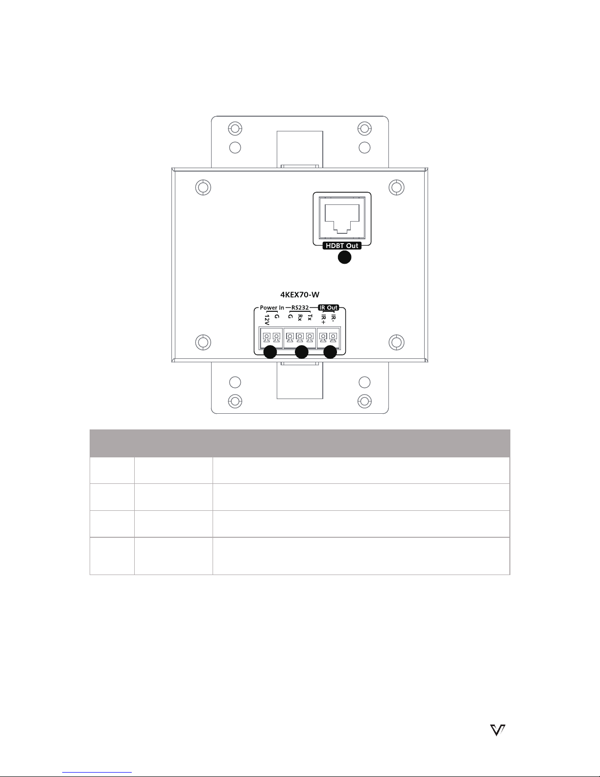
Rear Panel
No. Name Description
1 HDBT Out Connect to an HDBT receiver via a CATX cable.
2 Power In Connect to DC 12V power supply.
3 RS 232 RS 232 pass-through
4 IR Out
Connect to an IR emitter. IR emitter is not included in the
package.
1
2 3 4

www.avaccess.com
7
Installation Instructions
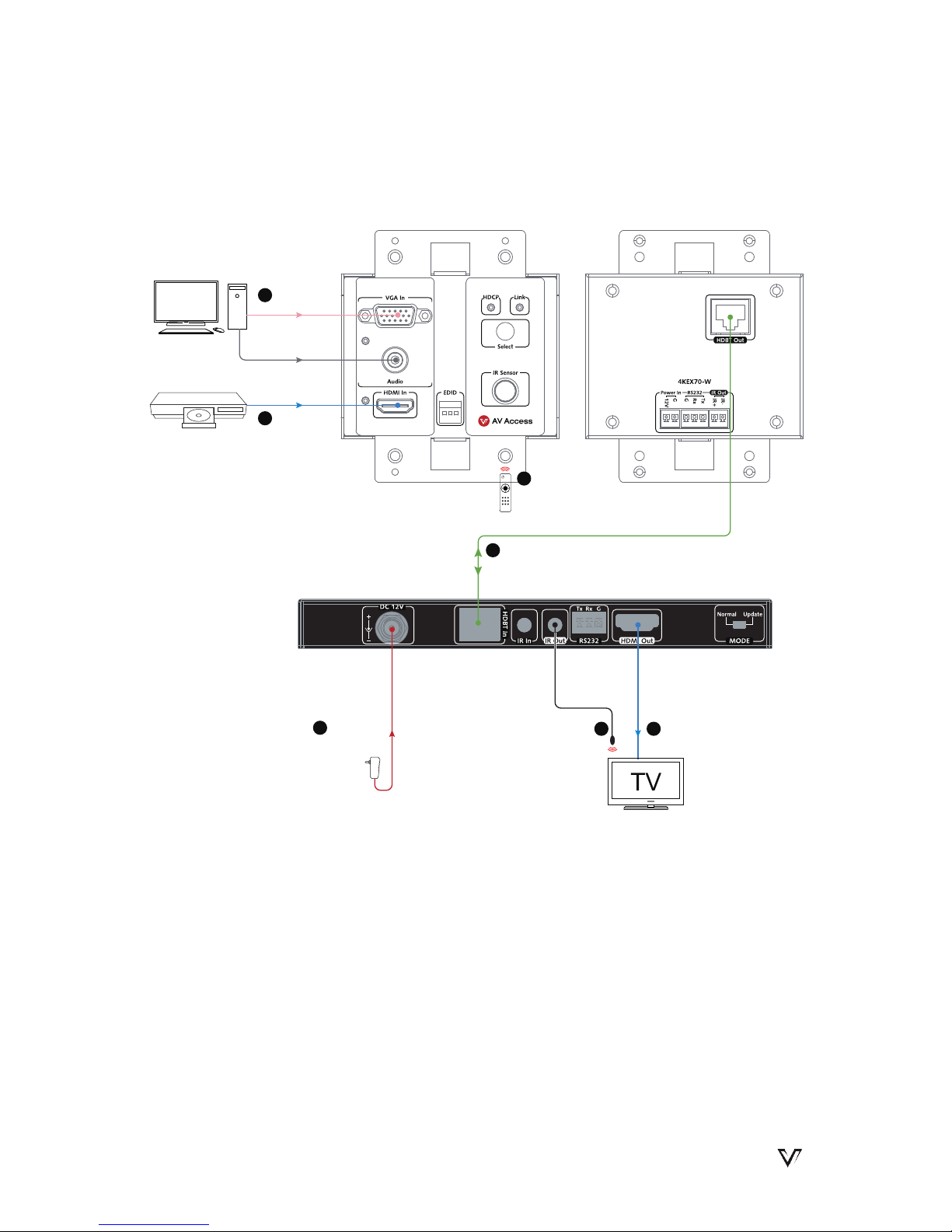
Installation Instructions
Bi-directional IR pass through enables users to control the source at the display
location or control the display at the source location with ease. Please refer to the
following two applied installations.
Applied installation 1:
Control the DVD at TV location with DVD remote
DVD RemotePower supply
Transmitter 4KEX70-W
6
Connect the IR emitter
on the rear panel
Note: The IR emitter head
should be secured over
the center of the DVD IR
window.
PC
Connect the
VGA source
1
2
Connect the
HDMI source
Connect the transmitter and receiver
via a Cat 5e / 6 / 7 cable.
Note: Ensure the Cat 5e / 6 cable
is within 197ft at 1080P, 115ft at 4K.
3
7
4
5
Connect the
power
Connect the
HDMI display
Connect the
IR receiver
4KEX70-RX-PSE
DVD
www.avaccess.com
8
Installation Instructions
Applied installation 2:
Note:
•
If the connected HDBT receiver doesn't include built-in PSE module, please
connect an external DC 12V power supply to the transmitter. Power supply is
not included in the package.
•
The IR emitter and IR receiver are not included in the package.
Control the TV at DVD location with TV remote
Transmitter 4KEX70-W
TV Remote
Power supply
6
PC
Connect the
VGA source
1
2
Connect the
HDMI source
Connect the transmitter and receiver
via a Cat 5e / 6 / 7 cable.
Note: Ensure the Cat 5e / 6 cable
is within 197ft at 1080P, 115ft at 4K.
3
4
Connect the
power
Connect the
HDMI display
4KEX70-RX-PSE
DVD
5
Connect the IR emitter
Note: The IR emitter head
should be secured over
the center of the TV IR
window.
7
Point the remote
at the IR Sensor
window

www.avaccess.com
9
Input Source Switch
Input Source Switch
4KEX70-W transmitter supports automatic and manual button switch between
the VGA and HDMI sources.
Users can manually switch input between the active HDMI and VGA sources as
required by pressing the "Select" button on the front panel.
1. Connecting to the sources before powering on all devices (Priority: HDMI >
VGA):
• Connect to both HDMI and VGA sources, power on all devices; the
HDMI source will be selected by default. Remove either source from the
transmitter; the remaining source will be automatically selected.
• Connect to either the HDMI or VGA source, power on all devices; the
active input source will be automatically selected.
Input
Output
HDMI VGA
Active Active HDMI
Active N/A HDMI
N/A Active VGA
2. Powering on all devices before connecting to the source(s):
• Power on all devices, connect to the HDMI source rst and VGA source
second; 4KEX70-W will output the HDMI signal.
• Power on all devices, connect to the VGA source rst and HDMI source
second; 4KEX70-W will output the VGA signal.
Automatic Switch
Manual Button Switch

www.avaccess.com
10
EDID Management
EDID (Extended Display Identification Data) is a data structure generated by a
digital display to communicate its capabilities, such as its native resolution, to the
attached source device.
For VGA input, fixed EDID output can be set using the EDID DIP switch on the
front panel.
The default setting is (0,1,0), please set EDID according to the following table:
Position 1 Position 2 Position 3 Functions
0 0 0 Output xed 1280 x 800 video
0 0 1 Output xed 1920 x 1200 video
0 1 0 Output xed 1920 x 1080 video (Default)
0 1 1 Output xed 1280 x 720 video
1 0 0 Output xed1024 x 768 video
1 0 1 Output xed 800 x 600 video
1 1 0 Not available
1 1 1 Not available
Note: Please plug out and in the VGA cable for EDID settings to take eect.
For HDMI input, the transmitter will copy and output the EDID of the connected
HDMI display.
EDID Management
1
1
0
2 3
ON
EDID DIP Switch

www.avaccess.com
11
Specication
Specication
Technical
Video Signal Type VGA, HDMI
Input / Output Resolution
Support
VGA:
640x480, 800x600, 1024x768, 1280x720,
1280x1024, 1920x1080, 1920x1200
8
HDMI:
SMPTE:
1280x720P
1,2,3,4,5,6,7,8
, 1920x1080I
6,8
,
1920x1080P
1,2,3,4,5,6,7,8
, 3840x2160
2,3,5,6,8
,
4096x2160
2,3,5,6,8
VESA:
800x6008, 1024x7688, 1280x7688, 1280x8008,
1280x9608, 1280x10248, 1360x7688, 1366x7688,
1400x10508, 1440x9008, 1600x9008, 1600x12008,
1680x10508, 1920x1200
8
1 = at 23.98 Hz, 2 = at 24 Hz, 3 = at 25 Hz, 4 = at
29.97 Hz, 5 = at 30 Hz, 6 = at 50 Hz, 7 = at 59.94
Hz, 8 = at 60 Hz
Note: 4096x2160/3840x2160@50Hz/60Hz is
based on chroma sub-sampling 4:2:0 8-bit only.
Audio Format
HDMI:
Stereo, PCM 5.1 / 7.1; Dolby True HD, DTS-HD
Master Audio
VGA: Stereo

www.avaccess.com
12
Specication
General
Operating Temperature 0°C to 45°C (32°F to 113°F)
Storage Temperature -20°C to 70°C (-4°F to 158°F)
Humidity 10% to 90%, non-condensing
ESD Protection
±8kV(Air-gap discharge)/
±4kV(Contact discharge)
Power Consumption
(Maximum)
3.36W
Device Dimensions
(W x H x D)
3.58'' x 1.16'' x 4.16''
(91mm × 29.4mm × 105.6mm)
Product Net Weight 0.18kg (0.4lb)
Cable Specications:
Note: AV Access recommends the use of T568B straight-through Category cables.
Cable Type Range Supported Video
HDMI
49ft (15m) 1080P@60Hz
33ft (10m) 4K@60Hz 4:2:0 8bit
CAT5e / 6
197ft (60m) 1080P@60Hz 36 bpp
115ft (35m)
1080P@60Hz 48bpp
1080P@60Hz 3D
4K@60Hz 4:2:0 8bit
CAT6a / 7
230ft (70m) 1080P@60Hz 36 bpp
131ft (40m)
1080P@60Hz 48bpp
1080P@60Hz 3D
4K@60Hz 4:2:0 8bit

www.avaccess.com
13
Trouble Shooting
Trouble Shooting
Steps of Regular Troubleshooting Routine
1. Power: Please make sure all devices are powered on (sources, transmitter,
receiver and display).
2. Indicator: Please make sure LED indicators of the transmitter and receiver are
normal according to user manual.
3. Devices: Please make sure picture can be shown normally when connecting
the source to the display directly.
4. Cable: Plug in and out HDMI / Cat X cable or try another HDMI / Cat X cable.
• Please make sure the specific cable length is within the transmission
range listed in below table based on dierent resolutions.
Resolution and Transmission Range
1080P@60
36bpp
1080P@60
48bpp
4K@60 420
HDMI IN 49ft 49ft 33ft
Cat 5e/6 197ft 115ft 115ft
Cat 6a/7 230ft 131ft 131ft
• Cat 5e/6/6a/7 cable is recommended. Do not use Cat 5 cable. Please
make sure the two connectors of one Cat X cable are the same standard
(EIA/TIA 568B).
5. Compatibility: Please test other source and display devices to determine if it
is a compatibility issue.
Cable
Resolution

www.avaccess.com
14
Trouble Shooting
1. How to deal with video ash or cut o during the installation?
• Link indicator should be solid on. If it is blinking or off, it is likely a
problem with your Ethernet cable. Please change to a qualified cable
(Cat5e/6/7, EIA/TIA 568B) and ensure the cable length is within the
maximum distance.
• HDCP indicator should be solid on or blinking. If it is off, it means no
signal pass through. Please check if the HDMI cables are well connected
to the source and TV, and the CATX cable that connects transmitter to
receiver is normal. Try a better HDMI cable or CATX cable.
2. How to deal with a weak or not working IR signal?
• Make sure the IR cables are correctly installed according to the
Installation Instruction diagram above.
• Check if the IR emitter head is secured over the center of the device IR
receiver window. The best position may vary depending on the device.
Please refer to the device user manual. If the signal is weak, please try to
adjust the position.
• Pay attention to the control angle and distance as below. The control
signal will be better when your controller is pointed at the IR receiver
head directly.
Enabled Angle 0° 30°(Horizontal) 15°(Vertical)
Distance 26ft (Max) 15ft (Max) 10ft (Max)
3. How can I make the IR work with third party control devices?
• Please make sure the third party device follows our pin definition as
below:
Typical Questions

www.avaccess.com
15
Trouble Shooting
• You can purchase an AV Access universal IR cable that will be compliant
with any third party device (Amazon ASIN: "B01MYX46IC").
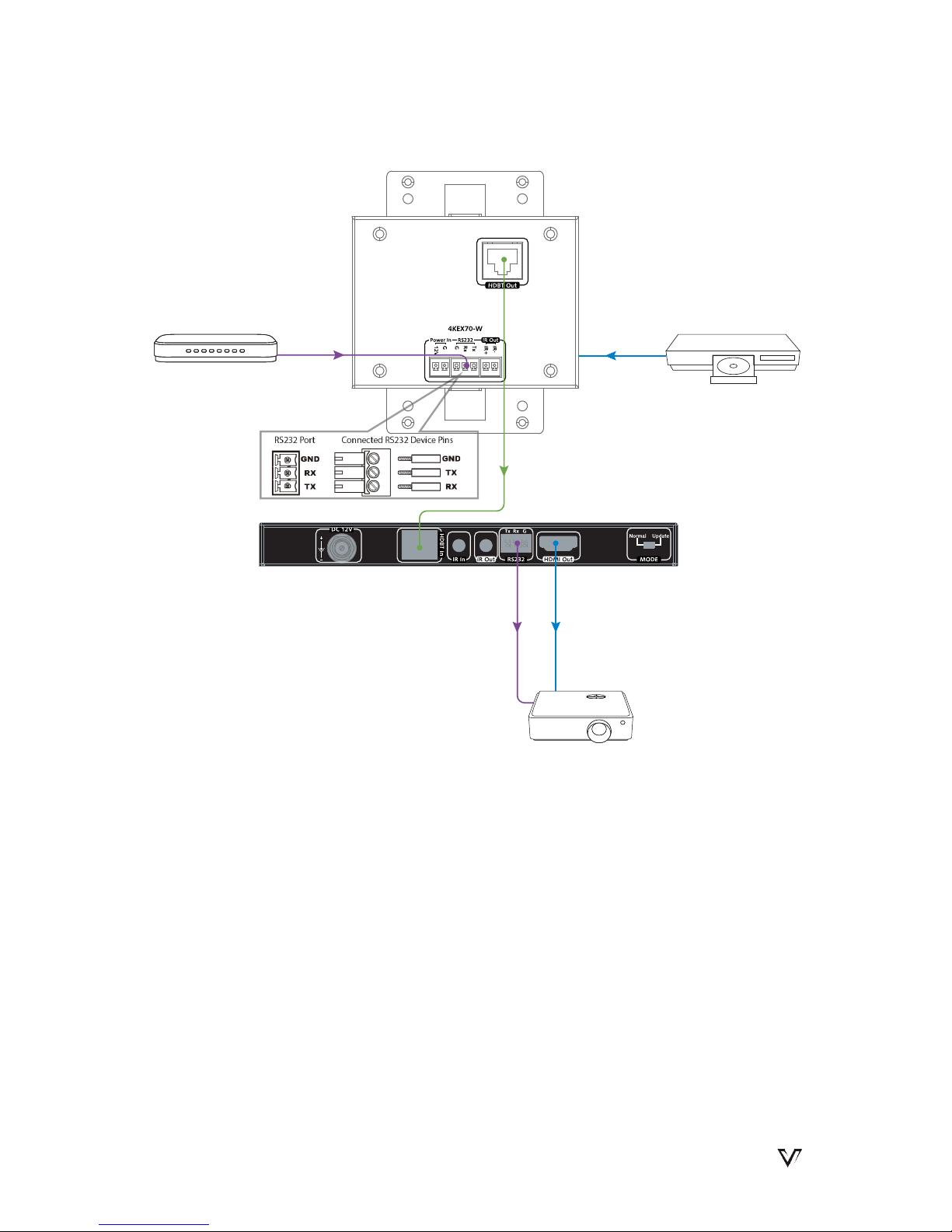
4. How to use the RS 232 port in the extender?
The RS 232 port provides a channel to pass through protocol commands to
control third party devices such as your source or display. RS 232 uses the
three pins that are labeled transmitter, receiver and GND. Connect a host
computer or control system to the RS 232 connector. Please refer to the
following pin denition of RS 232 during your installation.
IR Receiver
Gnd
IR signal
5V
IR Emitter
5V
IR signal
www.avaccess.com
16
Trouble Shooting
RS232 Cable
RS 232 Cable
Control System
Projector
HDMI In
CATX Cable
HDMI Out
DVD

www.avaccess.com
17
Warranty
Warranty
Products are backed by a limited 3-year parts and labor warranty. For the
following cases AV Access Technology Limited shall charge for the service(s)
claimed for the product if the product is still remediable and the warranty card
becomes unenforceable or inapplicable.
1. The original serial number (specified by AV Access Technology Limited)
labeled on the product has been removed, erased, replaced, defaced or is
illegible.
2. The warranty has expired.
3. The defects are caused by the fact that the product is repaired, dismantled
or altered by anyone that is not from an AV Access Technology Limited
authorized service partner. The defects are caused by the fact that the
product is used or handled improperly, roughly or not as instructed in the
applicable User Guide.
4. The defects are caused by any force majeure including but not limited to
accidents, re, earthquake, lightning, tsunami and war.
5. The service, configuration and gifts promised by salesman only but not
covered by normal contract.
6. AV Access Technology Limited preserves the right for interpretation of these
cases above and to make changes to them at any time without notice.
Thank you for choosing products from AV Access.


AV Access Technology Limited
V1.0.0
 Loading...