

AUX Highcool Operation Manuals
16
For further information telephone 01743 466333
Or visit our website at www.medalaircon.co.uk
Whilst every care has been taken to ensure that the information included in this document was accurate at the time of printing, we reserve the right to change specifications
at any time. The photographs reproduced in this publication are within the constraints of
the printing process and are NOT to be used for matching purposes. E&OE.
Read the Manual
Risk of Electric Shock Unit is Remotely controlled
& may start without warning
WARNING
This air conditioner is not intended for use by persons
(including children) with reduced physical, sensory or mental
capabilities, or lack of experience and knowledge, unless they
have been given supervision or instruction concerning use of
the appliance by a person responsible for their safety. Children
should be supervised to ensure they do not play with the air
conditioner or remote controller.
Ref— AUX wired controller
Highcool Series
Wired 7 Day Controller
for Cassette Air Conditioner
Operation Manual
2
INTRODUCTION
Highcool series cassette split systems are supplied as standard with the
Wired 7 Day Controller.
This controller is a sophisticated device designed to provide easy operation to a Highcool series cassette split system.
At its simplest, with the front panel shut, the controller can be used to
display relevant information about the units operation and allow the user
to switch the unit on and off.
Opening the controller front panel allows all of the controllers functions
to be accessed. Pressing any of the buttons below the front panel once
gives User Level Access. Pressing and holding certain buttons will give
Service Level Access.
At its most sophisticated the controller can switch the unit on or off at
different times each day of the week (or not run the unit at all on some
days). It can tell you what the unit is doing and whether it has a fault—
even what that fault is!
This manual is designed to show how the 7 Day Wired Controller can be
used to operate your Highcool cassette split system in order to get the
most from it.
CONTENTS
P2 Introduction
P3 General Description
P4 Display Section
P5 Control Buttons
P6—9 Understanding the Display
P10-12 Operating the Controller
P13 Caring for the Environment
P14 Appendix 1—Fault Codes
P15 Appendix 2—Engineers Notes
P15 Appendix 3—Timer Chart
P15 Fault Code Log
15
Appendix 2
Notes for Engineer
• The controller is provided with special screws for fixing it to the
wall. Please use these to avoid damaging the controller.
• The controller uses Low Voltage control cable—avoid running
this close to High Voltage cables in order to avoid interference
• The controller uses the RS485 data protocol. The cable colours
are Earth—Black, A—Green, B—Yellow, 12V—Red
Appendix 3
In order to assist with setting up the Weekly Timer you may use the
table below in order to record the settings for each day.
Day On Time AM/PM Off Time AM/PM ON/OFF
Monday
Tuesday
Wednesday
Thursday
Friday
Saturday
Sunday
Fault Code Log
In order to assist with the identification of any faults, please fill in the date, time, Fault
Code and Action Taken for each time a fault code is displayed.
DATE TIME CODE ACTION
14
Appendix 1
Fault Codes
The Error Check display area of the LCD display may, in the event of a fault, show the
symbol of a spanner and a fault code. This is a list of fault codes in order for you to
advise your service and maintenance engineer of the likely problem. Not all faults will
generate a fault code. Faults are divided into two types as below.
Recoverable Errors—P Codes
These faults will not always stop the unit but will affect its performance. They will clear
if the problem resolves itself.
Critical Errors—E Codes
These will cause the unit to shut down and should be investigated by an engineer as
soon as possible.
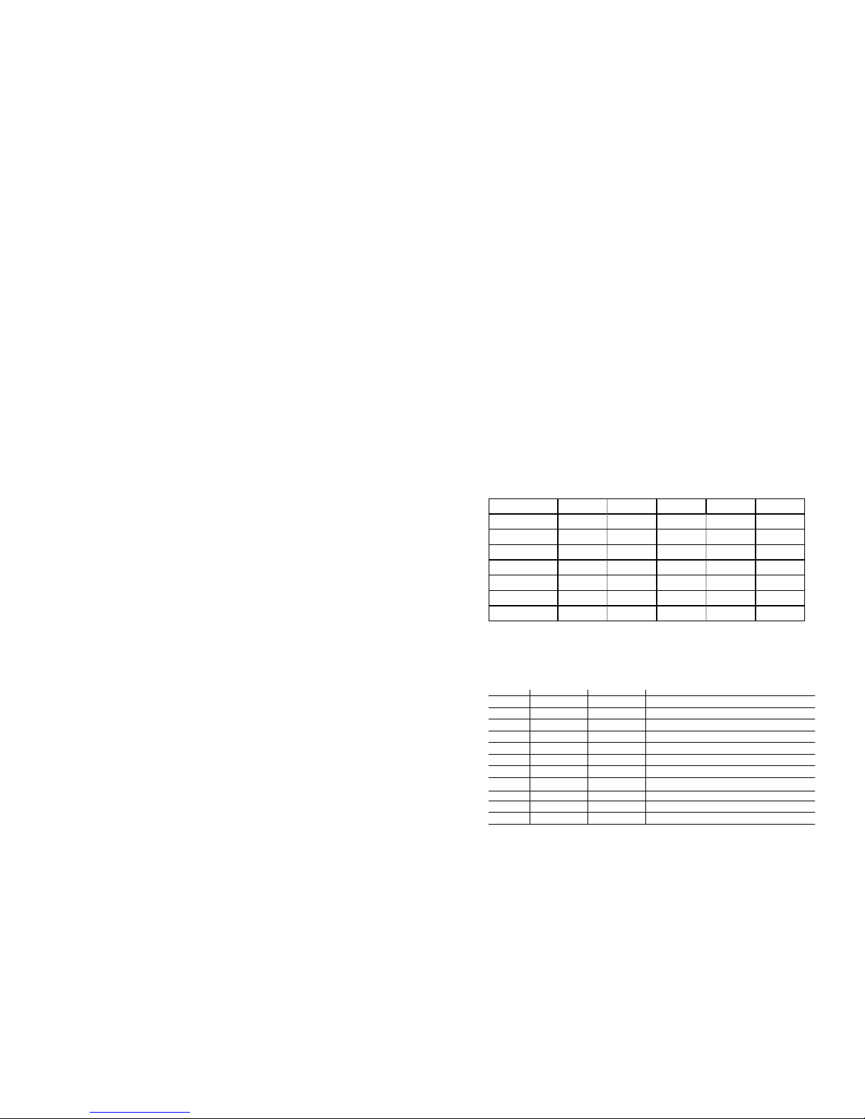
Code Ty pe Meaning Action Likely Cause
Pr01 Recov erable Indoor Unit Pipe Sensor Fault Repair Faulty Sensor
Pr02 Recov erable Outdoor Unit Pipe Sensor Fault Repair Faulty Sensor
Pr03 Recov erable Indoor Unit Freezing Inv estigate Dirty F ilter or Set Tem p Low
Pr04 Recov erable Ov erload Condition in Cooling Investigate Outdoor Unit Obstructed
Pr05 Recov erable Outdoor Discharge Sensor Fault Repair Faulty Sensor
Pr06 Recov erable Indoor Unit Air Sensor Fault Repair Faulty Sensor
Pr08 Recov erable Indoor Unit Ov erheating Inves tigate Dirty Filter or Set Temp High
Pr11 Recov erable Drain Pump Struggling to Cope Inves tigate Partially Bloc ked Drains
Eo00 Critical Comm s Fail Indoor to Control Repair Broken Cable or Interference
Eo03 Critical Electrical Phas e Problem Repair Pow er Supply Problem
Er04 Critical High Pressure Switch T rip Repair Safety Device Tripped
Er05 Critical Low Pressure Sw itch Trip Repair Safety Dev ice Tripped
Er06 Critical High Discharge T emperature Repair Safety Dev ice Tripped
Er07 Critical Ov ercurrent Protection Tripped Repair Safety Dev ice Tripped
Er08 Critical Comms Fail Indoor to Outdoor Repair Broken C able or Interference
Er11 Critical Drainage Failure Repair Blocked Drains
Er12 Critical Electric Heater Ov erheat Repair Safety Devic e Tripped
Explanation of Actions
•
Investigate—Non Critical Failure Requiring Investigation by an engineer
•
Repair—Critical Failure Requiring Investigation by an engineer
In the case of a Pr03 or Pr08 failure investigate yourself by checking the condition of the
filter and cleaning if necessary. Prolonged operation in cooling with a set temperature below
21C or heating above 26C can also cause these conditions.
In case of a Pr04 failure investigate yourself whether the outdoor unit airflow is obstructed.
3
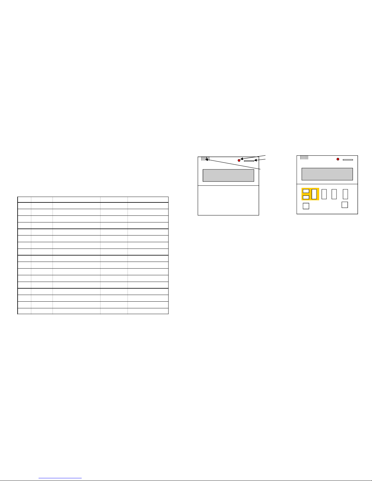
Flap Closed
Flap Open
Status LED
Operation
IR
Receiver
General Description
The controller has a Backlit Liquid Crystal Display Section, Status
LED and Operation Switch mounted on the top half. The lower
half is covered by a swing open flap.
Opening the flap reveals the control buttons. These are used to
operate the unit. The buttons with a yellow border control the
timer operation and the others control the units other functions.
Please Ensure -
• Do not operate the controller with wet hands
• Do not press multiple buttons simultaneously
• Do not press the buttons with sharp objects
• Ensure the Correct Button is Pressed
• Ensure all settings are in accordance with the Units User Manual
• Do not get the controller wet
 Loading...