

AUX AMCA-H12/4R1A, AMCA-H09/4R1A, AMCA-H18/4R1A Service Manual

AUX DC Inverter Free Match 50HZ R410A
1
SERVICE MANUAL
(DC Inverter Free Match R410a)

AUX DC Inverter Free Match 50HZ R410A General description
2
Table of Contents
Part 1 General information ..................................................................................................3
Part 2 Indoor unit .................................................................................................................7
Part 3 Free Match outdoor unit ......................................................................................... 68
Part 4 Trouble shooting ..................................................................................................... 96
Part 5 Controller .............................................................................................................. 124
Part 6 Sensor resistance table ....................................................................................... 135
AUX DC Inverter Free Match 50HZ R410A General description
3
Part 1General information
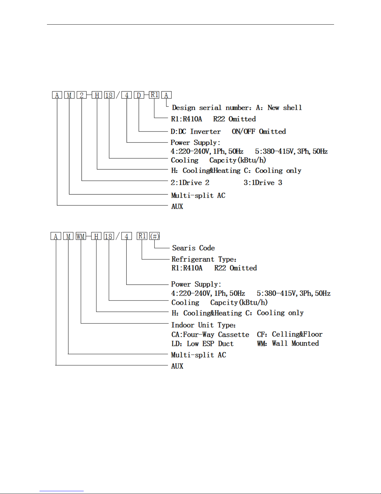
1. Nomenclature
Outdoor Unit
Indoor Unit
AUX DC Inverter Free Match 50HZ R410A General description
4
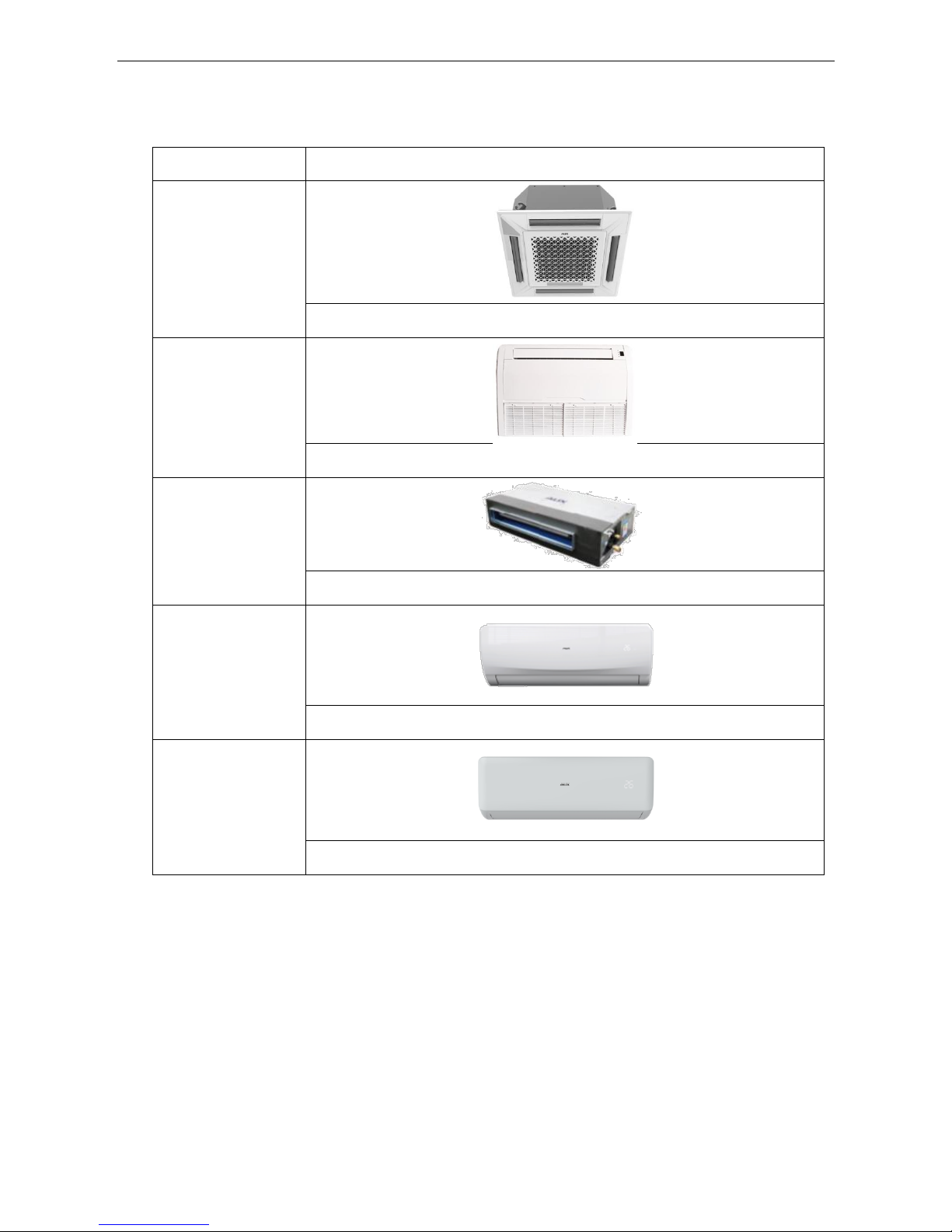
2. Unit Appearance
Series
Picture of the indoor unit
Four-way Cassette
(New)
9K~18K Btu/h
Ceiling &Floor
9K~18K Btu/h
Low ESP Duct
7K~18K Btu/h
Wall-mounted
(L Series)
7K~18K Btu/h
Wall-mounted
(F Series)
7K~18K Btu/h
AUX DC Inverter Free Match 50HZ R410A General description
5
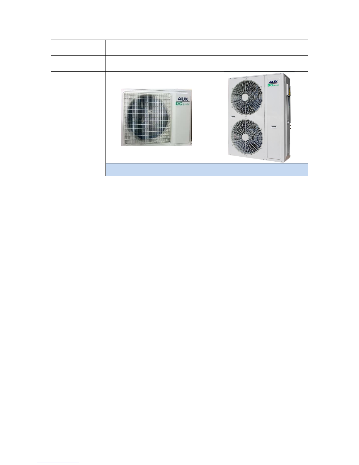
Series
Picture of the outdoor unit
Capacity(Btu)
18000
24000
27000
36000
42000
Outdoor Unit
(New)
1 drive 2
1 drive 3
1 drive 4
1 drive 5
AUX DC Inverter Free Match 50HZ R410A General description
6
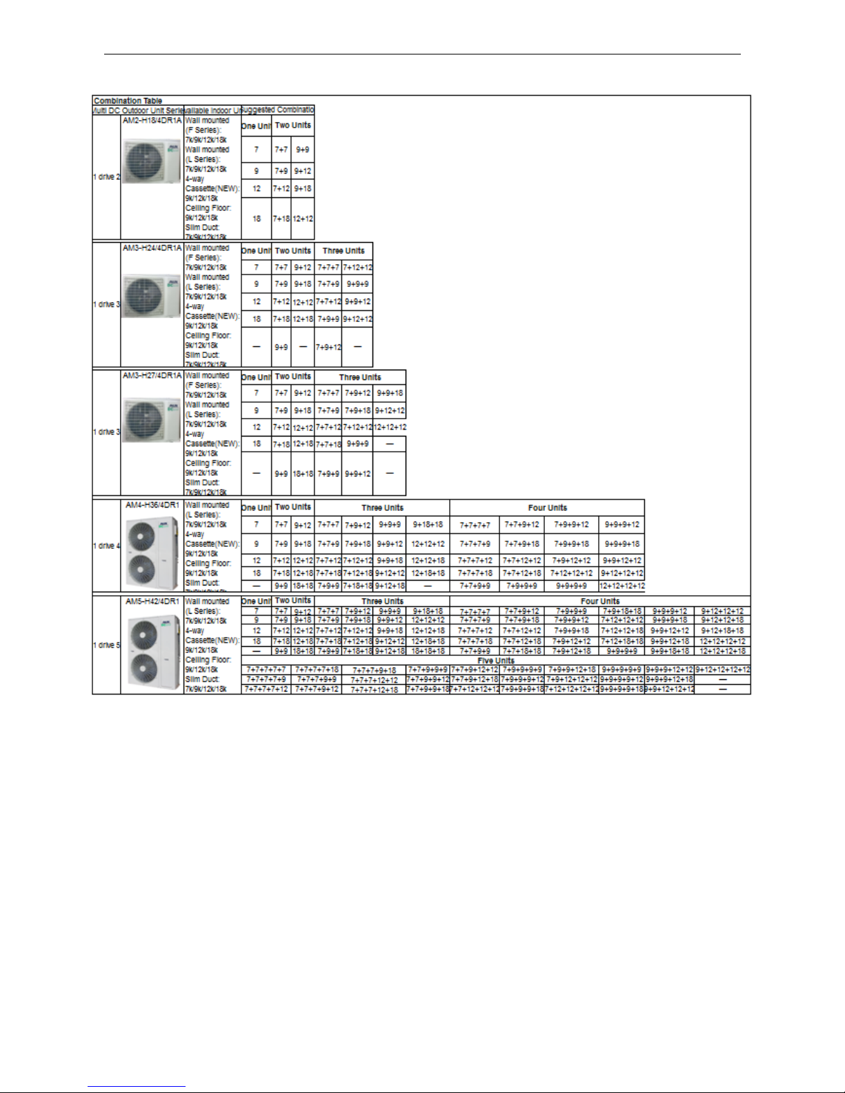
*Note:
① All of the above indoor unit can be freely matched and combined,but must be installed strictly
according to the above table.Orthe cooling capacity and stability would be decreased.
② The wall mounted indoor unit(F series) cannot be matched with the 36/42K outdoor unit.

AUX DC Inverter Free Match 50HZ R410A Indoor unit
7
Part 2 Indoor unit
Four-way cassette ...............................................................................................................5
Ceiling & floor type ............................................................................................................ 22
Low ESP Ducted Type ....................................................................................................... 35
Wall Mounted Type ............................................................................................................ 49

AUX DC Inverter Free Match 50HZ R410A Four-way cassette
8
Four-way cassette
1. Function Introduction .....................................................................................................9
2. Specification .................................................................................................................. 10
3. Capacity Amendment .................................................................................................... 11
4. Dimension ...................................................................................................................... 14
5. Electrical Diagram ......................................................................................................... 14
6. Installation ..................................................................................................................... 15
7. Explode view .................................................................................................................. 20
AUX DC Inverter Free Match 50HZ R410A Four-way cassette
9
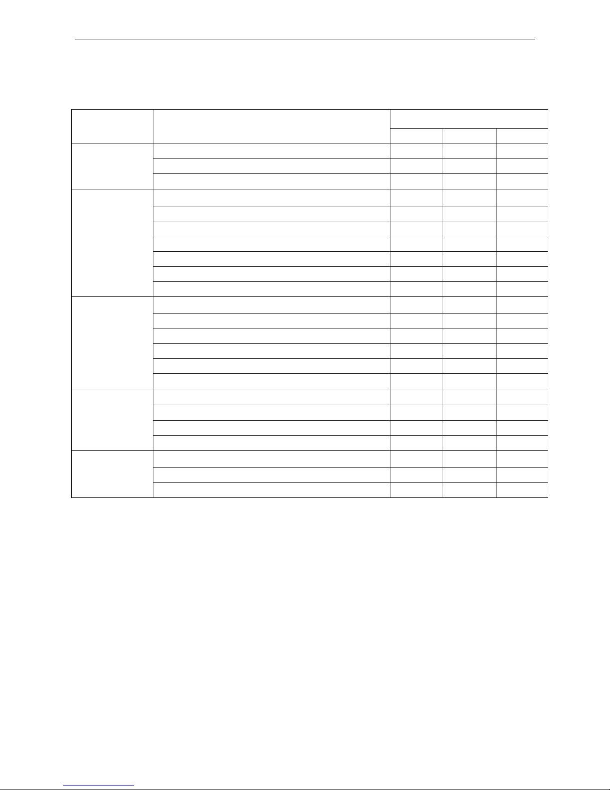
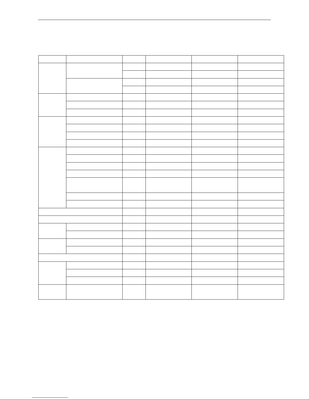
1. Function Introduction
Function
Name
AMCA-H*/4R1A
09
12
18
Protection
Function
Anti-freeze protection
○ ○ ○
Sensor failure alarm
○ ○ ○
Error code display function
○ ○ ○
Comfortable
Function
Cooling
○ ○ ○
Heating
○ ○ ○
3 fan speed
○ ○ ○
Auto-restart (optional)
○ ○ ○
Anti-cold wind
○ ○ ○
Blow exhaust heat
○ ○ ○
Timer
○ ○ ○
Opretating
display
Clock display
○ ○ ○
Operating mode display
○ ○ ○
Fan speed display
○ ○ ○
Defrosting display
○ ○ ○
Timing on/off display
○ ○ ○
Sleeping display
○ ○ ○
Operation
mode
Auto/Cool/Dry/Heat
○ ○ ○
Dehumidify operation
○ ○ ○
Auto defrosting
○ ○ ○
Ventilation function
○ ○ ○
Health
function
Removable air filter
○ ○ ○
Fresh air function preserved
○ ○ ○
Installation instruction plate is available
○ ○ ○
AUX DC Inverter Free Match 50HZ R410A Four-way cassette
10
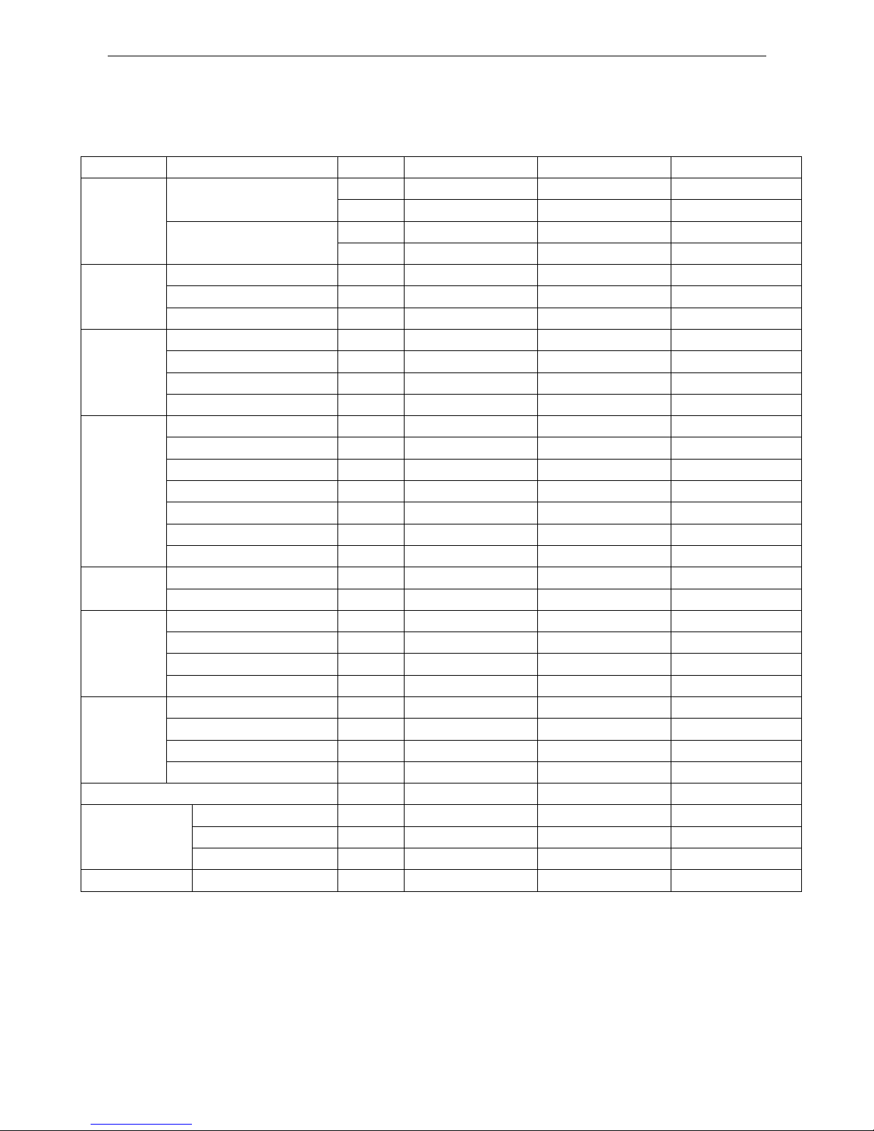
2. Specification
Model
Indoor
Unit
AMCA-H09/4R1A
AMCA-H12/4R1A
AMCA-H18/4R1A
Capacity
Cooling
Btu/h
9560(5120-12115)
12285(5800-12625)
17060(8530-19107)
kW
2.80(1.50-3.55)
3.60(1.70-3.70)
5.0(2.50-5.6)
Heating
Btu/h
10240(5460-13000)
13306(6930-15080)
19107(10340-24000)
kW
3.00(1.60-3.81)
3.9(2.03-4.42)
5.6(3.03-7.03)
Electric Data
Power Supply
V~,Hz,Ph
220~240,50,1
220~240,50,1
220~240,50,1
Cooling Power Input
W
70(17.5-109)
70(17.5-109)
70(17.5-109)
Heating Power Input
W
70(17.5-109)
70(17.5-109)
70(17.5-109)
Fan Motor
Model / XD30B
XD30B
XD30B
Output Power W 30
30
30
Capacitor
uF
2.0
2.0
2.0
Speed (Hi/Mi/Lo)
r/min
839/757/688
839/757/688
839/757/688
Indoor Coil
Number Of Row
/
2 2 2
Tube Pitchx Row Pitch
mm
20.5x 12.7
20.5x 12.7
20.5x 12.7
Fin Pitch
mm
1.5
1.5
1.5
Fin Material
/
Hydrophilic aluminum fin
Hydrophilic aluminum fin
Hydrophilic aluminum fin
Tube Outside Dia.&Material
mm
φ7, Inner grooved
φ7, Inner grooved
φ7, Inner grooved
Coil Length x Height x Width
mm
1352x205x 25.4
1352x205x 25.4
1352x205x 25.4
Heat Exchanging Area
m2
5.76
5.76
5.76
Performance
Air Flow Volume
m3/h
700/600/530
700/600/530
700/600/530
Sound Pressure Level
dB(A)
45/41/35
45/41/35
45/41/35
Dimension
Net Dim (W*D*H)
mm
570×570×260
570×570×260
570×570×260
Packing Dim (W*D*H)
mm
635x635x290
635x635x290
635x635x290
Net(Panel)
mm
650x650x55
650x650x55
650x650x55
Packing(Panel)
mm
710x710x80
710x710x80
710x710x80
Weight
Net(Body)
kg
18
18
18
Gross(Body)
kg
21
21
21
Net(Panel)
kg
3 3 3
Gross(Panel)
kg
5 5 5
Refrigerant Type
/
R410a
R410a
R410a
Pipe Dia
Liquid Side
mm(inch)
6.35(1/4)
6.35(1/4)
6.35(1/4)
Gas Side
mm(inch)
12.7(1/2)
12.7(1/2)
12.7(1/2)
Drainage
mm
20
20
20
Loading Qty
20/40/40H
unit
150/315/354
150/315/354
150/315/354
Note:
1. Cooling capacity test Condition:(27℃DB,19℃WB Indoor/35℃DB,24℃WB Outdoor);
Heating capacity test Condition:(20℃DB Indoor/7℃DB,6℃WB Outdoor);
connecting pipe length: 5M.
2. Datas may be changed withunit improvement. We keep the right to change the datas or specifications
withoutprior notice, please follow the datas listed on the nameplate.
AUX DC Inverter Free Match 50HZ R410A Four-way cassette
11
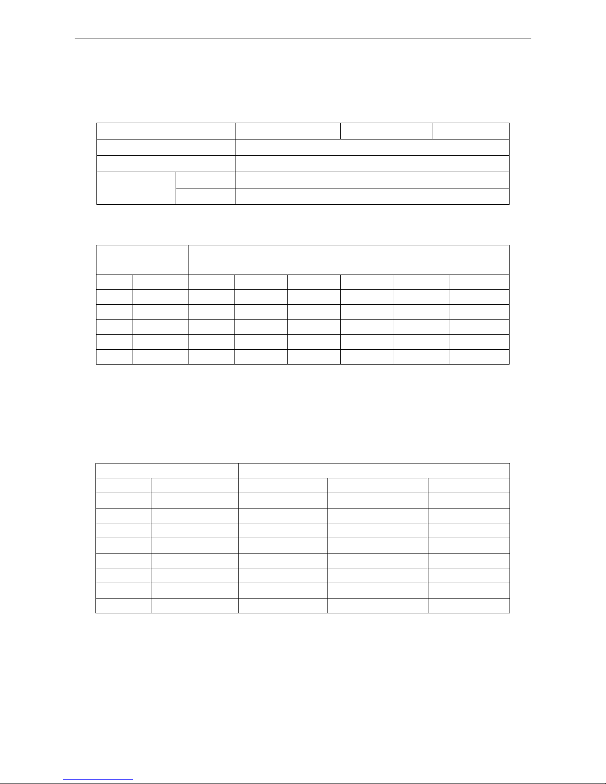
3. Capacity Amendment
3.1 Running range
Cooling capacity (Btu/h)
9000
12000
18000
Power supply
220-240V~/50Hz
Voltage
187~253V
Ambient
temperature
Cooling
-10~52℃
Heating
-15~24℃
3.2Amendment coefficient of cooling capacity under different indoor/outdoor
temperature(K1)
Indoor
temperature(℃)
Outdoor temperature(DB)
DB
WB
25
30
35
40
45
50
22
15
0.97
0.92
0.87
0.96
0.77
0.75
24
17
1.03
0.98
0.94
0.89
0.84
0.80
27
19
1.10
1.05 1 0.95
0.90
0.86
29
21
1.16
1.11
1.06
1.02
0.96
0.91
32
23
1.22
1.17
1.13
1.08
1.02
0.98
Actual cooling capacity calculation:
Actual cooling capacity=amendment coefficient of cooling capacity × nominal cooling capacity
——nominal cooling capacity could be found from the performance parameters list
——amendment coefficient of cooling capacity could be found from table above.
3.3 Amendment coefficient of heating capacity under different indoor/outdoor DB/WB
temperature K2
Outdoor temperature(℃)
Indoor temperature(DB)
DB
WB
15
20
25
-15
-16
0.64
0.59
0.55
-10
-12
0.71
0.66
0.62
-7
-8
0.76
0.72
0.67
-1
-2
0.79
0.74
0.70 2 1
0.81
0.76
0.72 7 6
1.04
1
0.96
10 9 1.10
1.06
1.01
15
12
1.16
1.12
1.07
Actualheatingcapacity calculation:
Actual heating capacity=amendment coefficient of heating capacity × nominal heating capacity
——nominal heating capacity could be found from the performance parameters list
——amendment coefficient of heating capacity could be found from table above.

AUX DC Inverter Free Match 50HZ R410A Four-way cassette
12
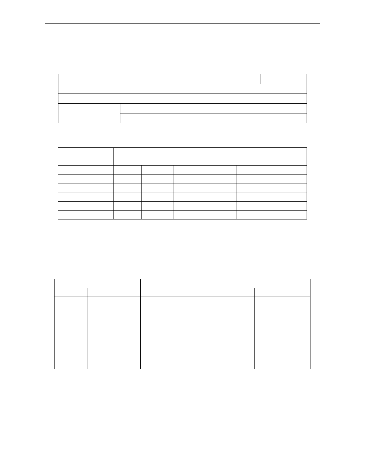
3.4 Amendment coefficients of heating and cooling capacity under different height
drop K3
Different Cooling Capacity modified coefficients at different height:
Note:
H = Height of Outdoor Unit - Height of Indoor Unit
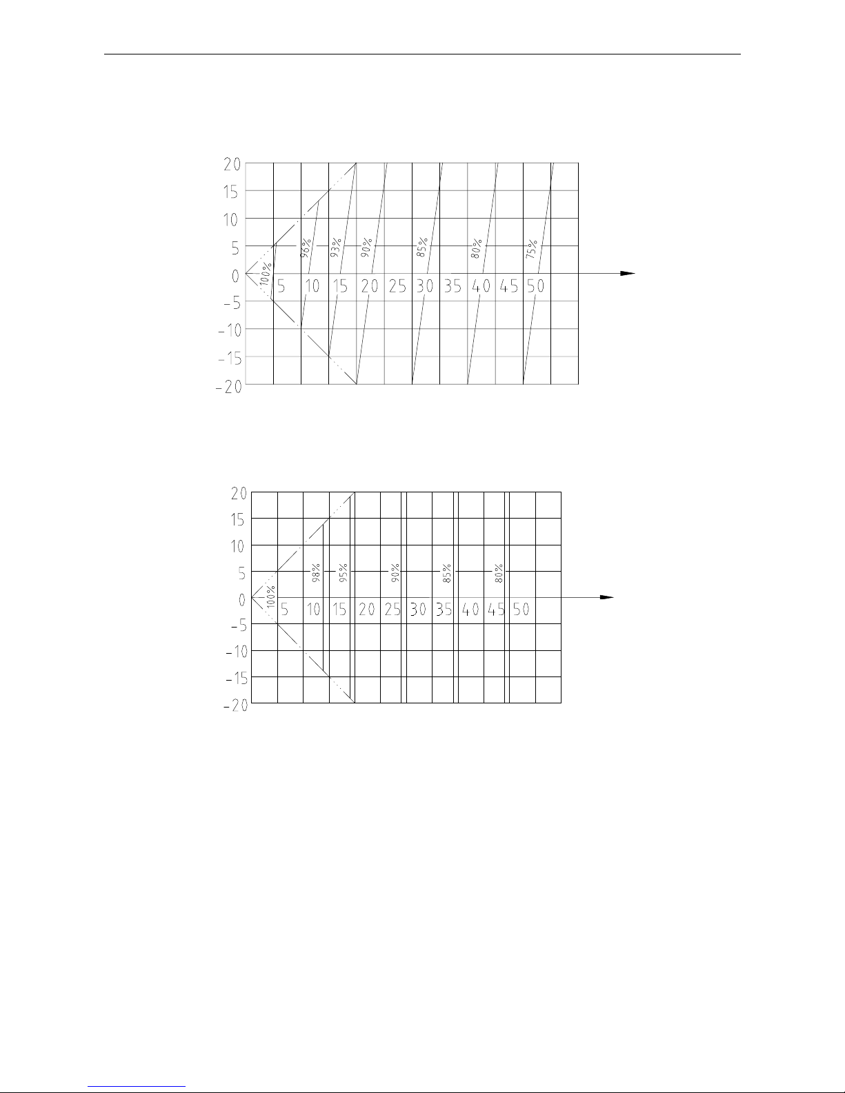
Different Heating Capacity modified coefficients at different height:
Note:
H = Height of Outdoor Unit - Height of Indoor Unit
3.5 Correction capability
Cooling capacity = nominal cooling capacity xK1xK3
Heating capacity = nominal heating capacity xK2xK3
3.6 Equivalent Pipe length conversion
Equivalent pipe length means converting pipe elbow to straight pipe length after considerate the pressure
loss.
Height D
ifference H(m)
Cooling
Equivalent pipe length EL (m)
Height D
ifference H(m)
Equivalent pipe lengthEL(m)
Heat
ing
AUX DC Inverter Free Match 50HZ R410A Four-way cassette
13
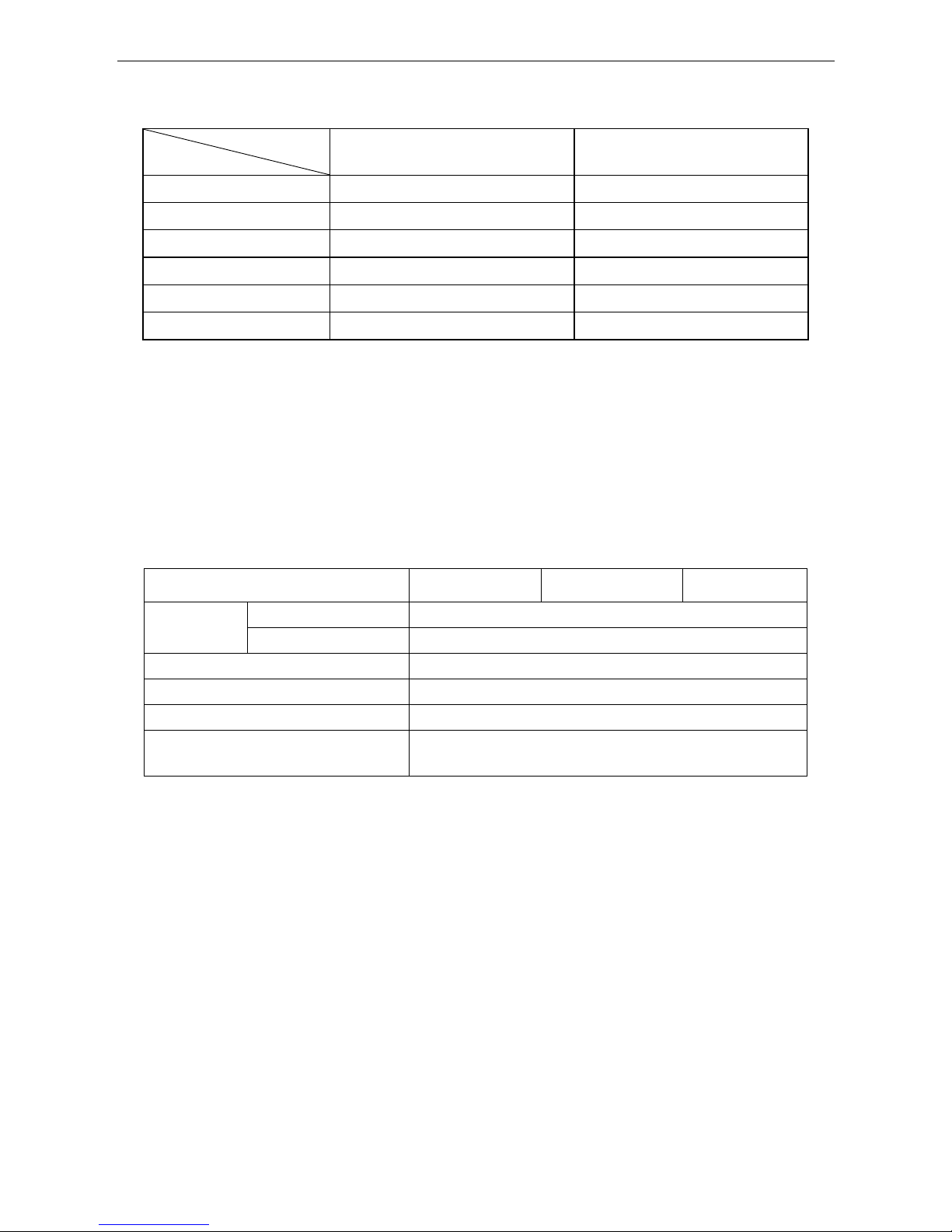
Bend and Oil Loop Conversion tablet
Type
Pipe Dia.(mm)
Bend
Oil Loop
6.35
0.10
0.7
9.52
0.18
1.3
12.70
0.20
1.5
15.88
0.25
2.0
19.05
0.35
2.4
22.02
0.40
3.0
Equivalent Pipe length L=Actual Pipe length L+ Bend Qty× Equivalent pipe bend length+ Oil Loop Qty ×
Equivalent Oil Loop length
Sample:
AMCA-H09/4R1AActual Pipe length is 25 meters, Gas pipe diameter is 9.52mm. If there’s 5 bends and 2
oil loops during the installation, then the equivalent pipe length should be:
L=25+0.18×5+1.3×2=28.5(m)
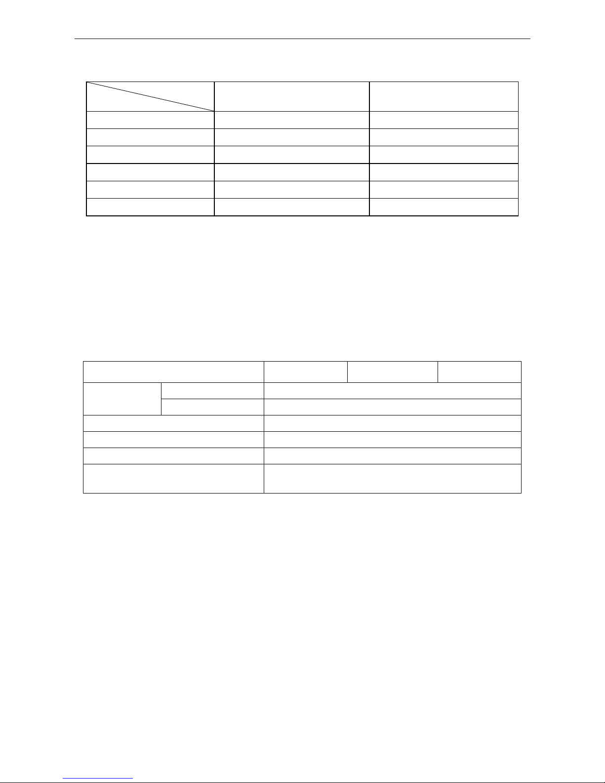
◇Specification of Connection Pipe for Indoor Unit and Outdoor Unit
Cooling Capacity(Btu/h)
9000
12000
18000
Connection Pipe
(mm)
Liquid Pipe
Φ6.35
Gas Pipe
Φ12.7
Max. Length(Each)
15
Max. Height (m)
10
Max. Bend Qty
5
Extra R410a per meter when the pipe length is
more than 5 meter (kg)
0.022
Caution:
1. The standard Pipe length is 5m, if the pipe length is less than this then no additional charging is
necessary. If the pipe length is more than this then you should charge more refrigerant into the system
according to the above Charging Data
2. The thickness of the pipe is 0.6-1.0, bearing pressure is 4.2MPa;
3. If the connection pipe is too long, the cooling capacity and stability would be decreased. And the more
bend quantity, the resistance in the piping system would be bigger, then the cooling and heating
capacity would be decreased even lead to compressor broken. We suggest you to use the shortest
connection pipe according to the pipe length parameter in this manual.If the height difference between
outdoor and indoor unit is more than 5m, an oil trap should be installed in the gas pipe for every 10
meters.
AUX DC Inverter Free Match 50HZ R410A Four-way cassette
14
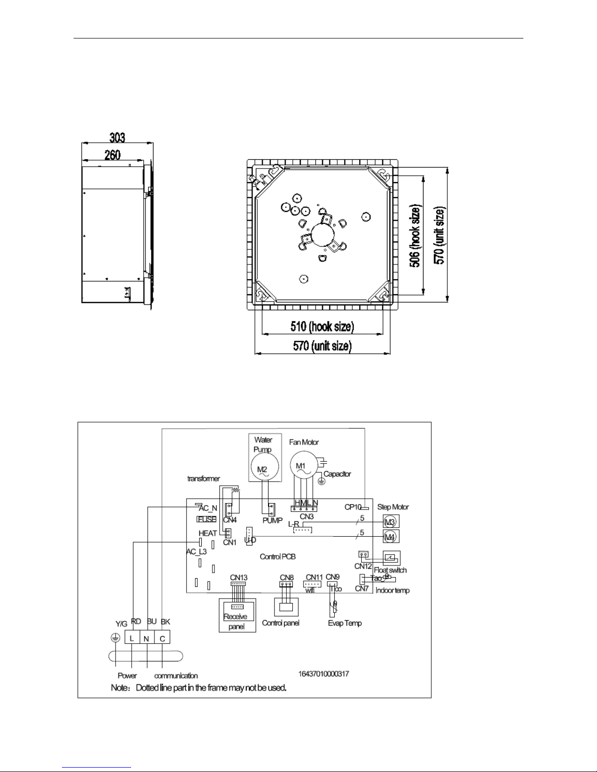
4. Dimension
AMCA-H09/4R1A, AMCA-H12/4R1A, AMCA-H18/4R1A
5. Electrical Diagram
AMCA-H09/4R1A, AMCA-H12/4R1A, AMCA-H18/4R1A
AUX DC Inverter Free Match 50HZ R410A Four-way cassette
15
6. Installation
6.1 Preparation before installation
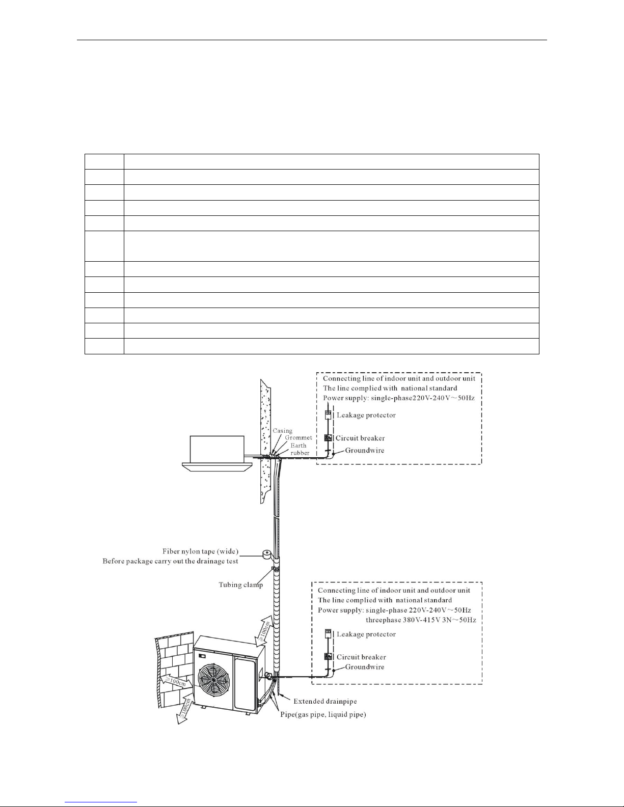
6.1.1Please buy following spare parts from your local market before installation
1
Hung bolts M12, 4 pcs
2
Drainage pipe PVC
3
Copper pipe
4
Adhesive belt (big size) 5 pcs, (small size) 5 pcs
5
Heat insulation material used to connect copper pipe (PE foam material, its thickness is more than 8mm)
6
Power cable, electrical wire between indoor and outdoor unit(Must be in accordance with the wire diameter
in the wiring diagram)
7
Acetylene cylinders, oxygen cylinders (when longer pipe used it should be welded)
8
One set pipe cut machine. (cut copper pipe)
9
Refrigerant cans, electronic balance (when longer pipe used additional gas should be charged)
10
Pressure gauges, pipe clamp, welding torch, 2B silver electrode
11
Wrench 2 pcs, one of them is with adjustable torque wrench(42N.m,65N.m,100N.mm)
12
Nitrogen cylinder (in order to prevent oxidation when welding, using Nitrogen to replace the air)
6.2 Installation drawing
AUX DC Inverter Free Match 50HZ R410A Four-way cassette
16
6.3 Installation precaution
◇ Hanging location should be able to support the unit’s weight, there should be no increasement in
noiseand vibration. If the hanging location needs reinforcement, it should be reinforced before
installation;
◇ Choose the space above the ceiling that can put the indoor unit inside;
◇ The location should be easy for drainage;
◇ The unit should not be installed in the heat source, steam or oil mist source (such as machine room,
kitchen, laundry room, mechanical workshop, etc.)
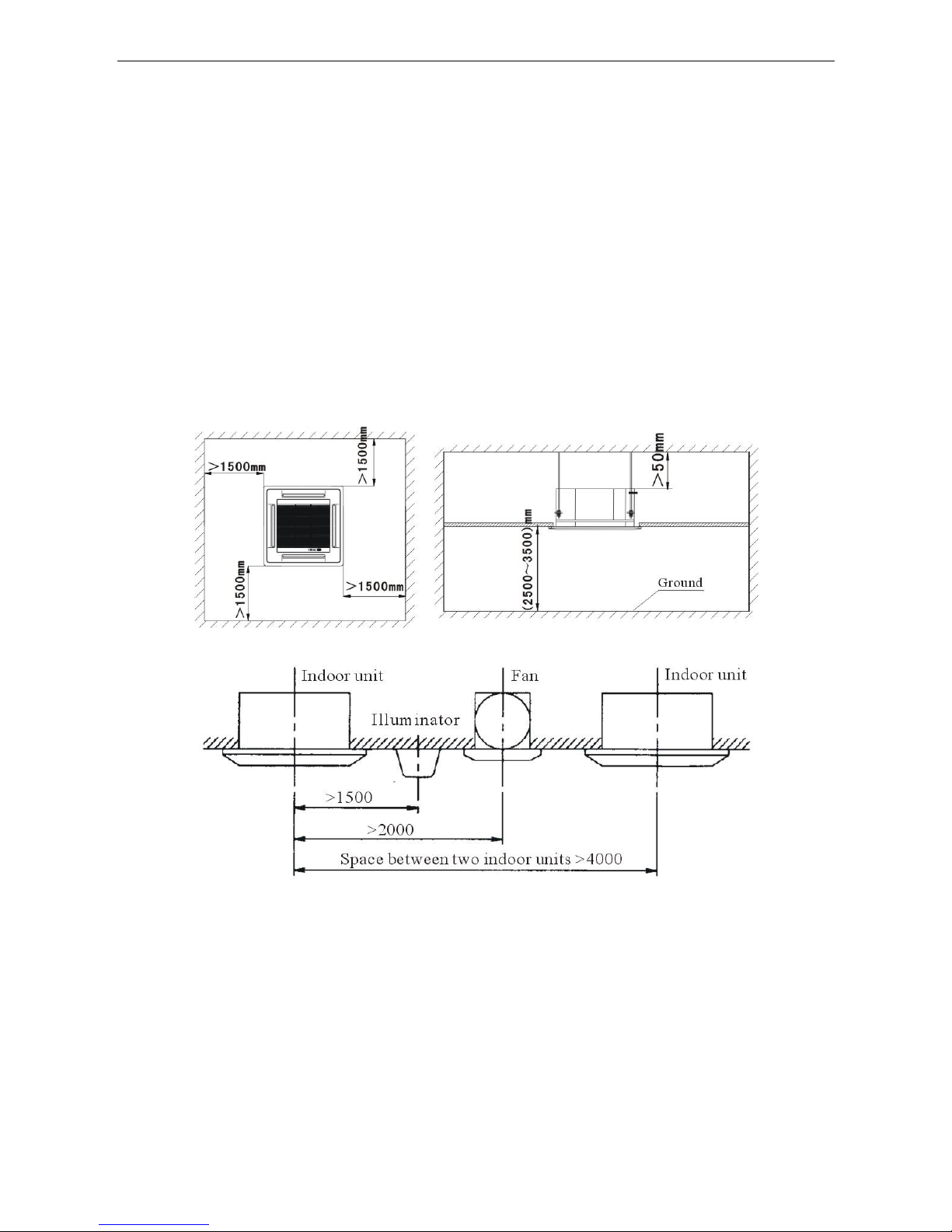
◇ Choose the location at least 1 meter away from TV and radio, in order to avoid interference to them
◇ There should be certain distance between indoor unit and obstaclesfor maintenance;
◇ In case of leakage of refrigerant, units should immediately stop running, and contact with maintenance
personnel in time. There must be no fire at the site, because the refrigerant will turn to harmful gas
when get to the fire.
6.4 The distance between indoor unit and obstacle
AUX DC Inverter Free Match 50HZ R410A Four-way cassette
17
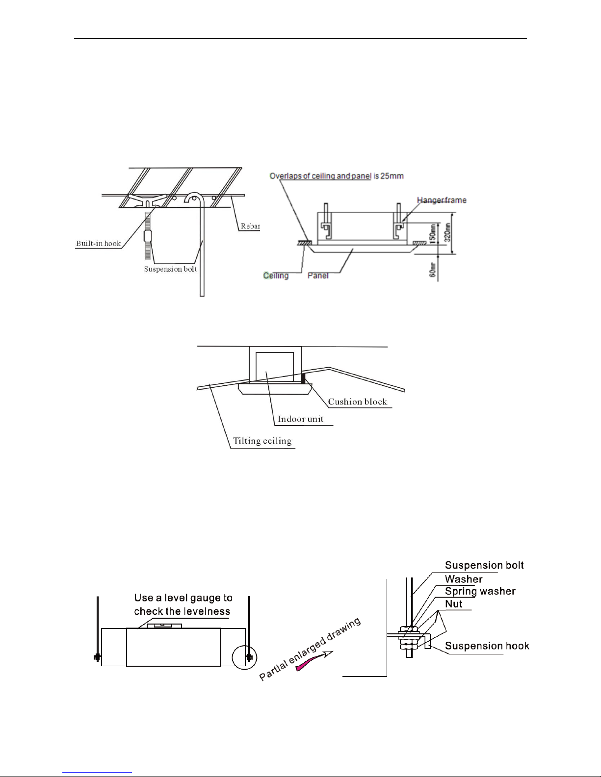
6.5 Indoor unit suspension
◇ Select the suspension foundation:
The suspension foundation is a structure of either wooden frame or reinforced concrete. It must be
firm and reliable to bear at least 4 times weight of itself and capable of bearing vibration for long
periods.
◇ Fixing of suspension foundation:
◇ Fix the suspension bolts either as shown in the picture or by a steel or wooden bracket.
◇ If this unit is installed on a sloping ceiling, a cushion block should be installed between the ceiling and
the air outlet panel, in order to ensure that the unit is installed on a level surface.
This is as shown in the drawing as follows:
◇ Adjust the relative position of the suspension hook on the suspension bolt so that the unit can be in
level position in all directions. Check with a level gauge after installation to ensure that the indoor unit
is horizontal, otherwise it will cause water leakage, air leakage etc.
◇ Tighten the bolt and ensure that four hooks are in close contact with the nuts and washers,to fix the
indoor unitunder the ceiling.
◇ After the unit is installed ensure it is secure and does not shake or sway.
◇ Ensure that the centre of the indoor unit is in alignment with the centre of the opening in the ceiling.
AUX DC Inverter Free Match 50HZ R410A Four-way cassette
18
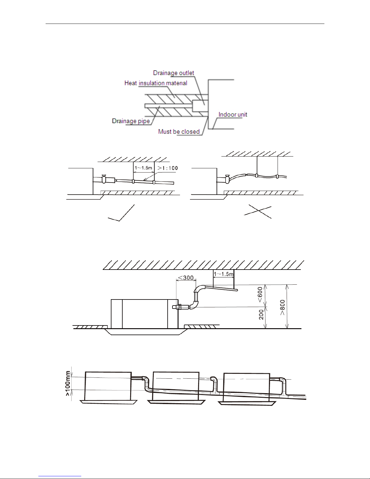
6.6 Drainage pipe installation
The drainage pipe should be properly insulated to prevent the generation of condensation.Heat insulation
material: the thickness of rubber insulation pipe should be more than 8mm
◇ Drainage pipe must have a downward gradient (1 / 50 1 / 100) to avoid water backflow or leakage etc.
◇ The unit has a drain pump which will lift up to 1200mm. However after the pump stops the water left in
the pipe will drain back and may overflow the drain tray causing water leakage. For this reason please
install the drain pipe as shown
◇ When draining multiple units into a common drain line, this common drain should be installed about
100mm below each units drain outlet, as shown in the drawing.
◇ When finish installation please carry out the drainage test to ensure that the water flow through the

AUX DC Inverter Free Match 50HZ R410A Four-way cassette
19
pipeline fluently, and carefully observe the junction to ensure that there is no water leakage. If the unit
is installed in the newly built house, strongly recommend that this test taken before the ceiling
installation. Even it is the heating only unit, this test is unavoidable.
6.7 Panel installation
As to the MB13 panel please refer to the following picture, the panel has four hooks which attach to
corresponding hangers on the unit and the panel should be positioned using these first. The panel is then
fixed into position by four bolts which are accessed through the four corner panels on the grille.
AUX DC Inverter Free Match 50HZ R410A Four-way cassette
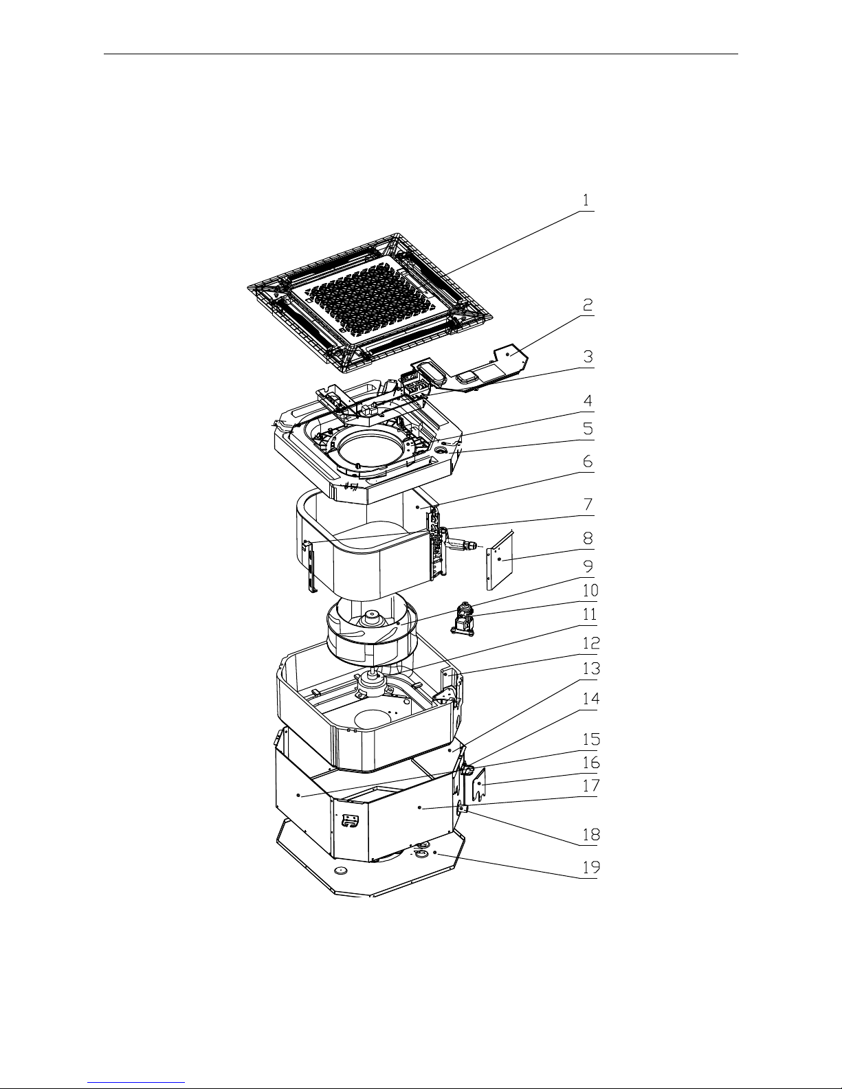
20
7. Explode view
AMCA-H09/4R1A, AMCA-H12/4R1A, AMCA-H18/4R1A
AUX DC Inverter Free Match 50HZ R410A Four-way cassette
21
No.
BOM Code
Part Name
Qty
Remark
1
16108022000016
Panel MB13 new 1
1.1
16420010000015
Return-air grille assembly
1 1.2
16420012000012
Air filter net 1
1.3
16420007000023
guide wind vane 4
1.4
16430001000133
Step motor
4
24BYJ48-2
1.5
16422015000007
Display board
1
SX-DISP-01
1.6
16420014000035
Panel frame assembly
1 2
16321005000025
Cover for electric components
1 3
16330001000016
Electric assembly
1 3.1
11330010000089
capacitance
1
2.5μF/450V a.c
3.2
11222542000029
PCB board
1
QRD-SN3F(18-60)K(485)-SYE1(SY)
3.3
16422005000017
Transformer
1
TDB-14-B4B(PTC)
3.4
16427001000064
Terminal board
1
600V 2.5mm2
3.5
16430007000007
Sensor 1
1
20K3950 XH2
3.6
16430007000003
Sensor 2
1
15K3950 XH2
4
16320005000040
Water pan 1
5
16432016000037
Rubber plug 1
6
16324005000082
Evap assembly 1
6.1
16325005000086
Evap part 1
6.2
16325005000087
Evap outlet tube assembly
1 6.3
16421024000110
Evap inlet tube assembly
1 7
16421007000143
Evap Pothook 2
8
16444001000037
Evaporator connect board
1 9
16330005000017
Wind wheel
1
Ф283×166
10
16421026000368
Drain pump
1
PLD-700
10.1
16430001000638
Bodder switch 1
10.2
16421040000053
Drain pump support
1 11
16430001000638
Fan motor
1
XD30B
12
16421040000042
Water pan holder
1
13
16421010000073
Air Blower EPS 4
14
16421014000089
Pothook 4
15
16421010000072
Boarding A 1
15.1
16432019000008
Boarding B 1
16
16321001000071
Valve board 1
17
16108022000016
Boarding B 1
18
16420010000015
Plastic drainage pipe
1 19
16420012000012
Chassis 1

AUX DC Inverter Free Match 50HZ R410A Ceiling & Floor Type
22
Ceiling & floor type
1. Function Introduction ......................................................... Error! Bookmark not defined.
2. Specfication ................................................................................................................... 24
3. Capacity amendment .................................................................................................... 25
4. Dimension ...................................................................................................................... 28
5. Electrical Diagram ......................................................................................................... 29
6. Installation ..................................................................................................................... 30
7. Explode view .................................................................................................................. 33
AUX DC Inverter Free Match 50HZ R410A Ceiling & Floor Type
23
1. Function Introduction
Function
Name
AMCF-H*/4R1
09
12
18
Protection
Function
Anti-freeze protection
○ ○ ○
Sensor failure alarm
○ ○ ○
Error code display function
○ ○ ○
Comfortable
Function
Cooling
○ ○ ○
Heating
○ ○ ○
3 fan speed
○ ○ ○
Auto-restart (optional)
○ ○ ○
Anti-cold wind
○ ○ ○
Blow exhaust heat
○ ○ ○
Timer
○ ○ ○
Opretating
display
clock display
○ ○ ○
operating mode display
○ ○ ○
fan speed display
○ ○ ○
defrosting display
○ ○ ○
timing on/off display
○ ○ ○
sleeping display
○ ○ ○
Operation
mode
Auto operation
○ ○ ○
Dehumidify operation
○ ○ ○
Auto defrosting
○ ○ ○
Ventilation function
○ ○ ○
Health
function
Removable air filter
○ ○ ○
AUX DC Inverter Free Match 50HZ R410A Ceiling & Floor Type
24
2. Specfication
Model
Indoor
Unit
AMCF-H09/4R1
AMCF-H12/4R1
AMCF-H18/4R1
Capacity
Cooling
Btu/h
9560(5120-12115)
12285(5800-12625)
18080(8530-19107)
kW
2.80(1.50-3.55)
3.60(1.70-3.70)
5.3(2.50-5.6)
Heating
Btu/h
10240(5460-13000)
13306(6930-15080)
19790(10340-24000)
kW
3.00(1.60-3.81)
3.9(2.03-4.42)
5.8(3.03-7.03)
Electric
Data
Power Supply
V~,Hz,Ph
220~240,50,1
220~240,50,1
220~240,50,1
Cooling Power Input
W
80(20-125)
80(20-125)
80(20-125)
Heating Power Input
W
80(20-125)
80(20-125)
80(20-125)
Fan Motor
Model / YSK-25W-4
YSK-25W-4
YSK-40W-4
Output Power W 25
25
40
Capacitor
uF
1.5
1.5
2.5
Speed (Hi/Mi/Lo)
r/min
1030/866/735
1030/866/735
1250/1100/900
Indoor Coil
Number Of Row
/
2 2 3
Tube Pitchx Row Pitch
mm
20.5x 12.7
20.5x 12.7
20.5x 12.7
Fin Pitch
mm
1.6
1.6
1.6
Fin Material
/
Hydrophilic aluminum
Hydrophilic aluminum
Hydrophilic aluminum
Tube Outside Dia.&
Material
mm
φ7, Inner grooved
φ7, Inner grooved
φ7, Inner grooved
Coil L x H x W
mm
599x246x 25.4
599x246x 25.4
599x246x 38.1
Heat Exchanging Area
m2
4.21
4.21
6.32
Air Flow volume
m3/h
620/504/441
620/504/441
850/680/595
Sound Pressure Level
dB(A)
39/36/30
39/36/30
43/39/36
Dimension
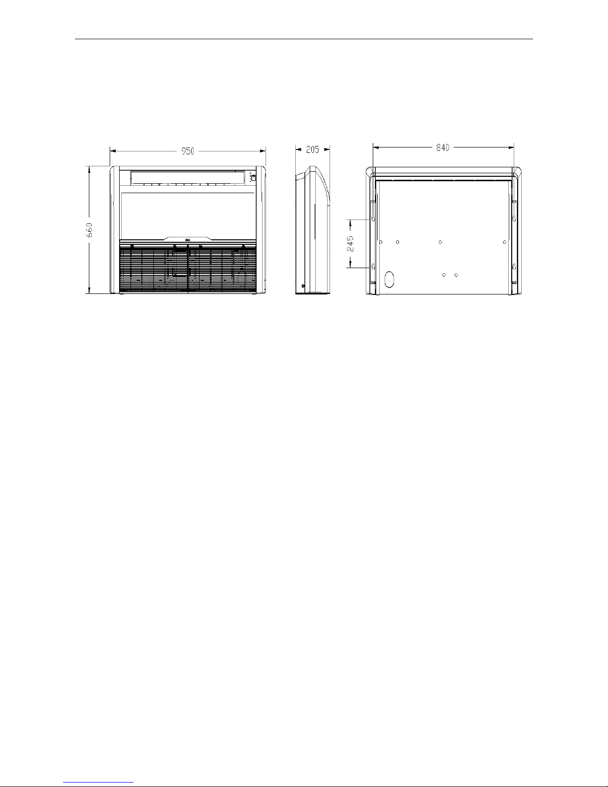
Net Dim(W*D*H)
mm
929×660×205
929×660×205
929×660×205
Packing Dim(W*D*H)
mm
1010×720×290
995×710×280
995×710×280
Weight
Net
kg
24
24
25
Gross
kg
27
27
28
Refrigerant Type
/
R410a
R410a
R410a
Pipe Dia
Liquid Side
mm(inch)
6.35(1/4)
6.35(1/4)
6.35(1/4)
Gas Side
mm(inch)
12.7(1/2)
12.7(1/2)
12.7(1/2)
Drainage
mm
20
20
20
Loading
Qty
20/40/40H
unit
136/280/315
136/280/315
136/280/315
Note:
1.Cooling capacity test Condition:(27℃DB,19℃WB Indoor/35℃DB,24℃WB Outdoor);
Heating capacity test Condition:(20℃DB Indoor/7℃DB,6℃WB Outdoor);
connecting pipe length: 5M.
2.Datas may be changed with unit improvement. We keep the right to change the datas or specifications
withoutprior notice, please follow the datas listed on the nameplate.
AUX DC Inverter Free Match 50HZ R410A Ceiling & Floor Type
25
3. Capacity amendment
3.1 Running range
Cooling capacity (Btu/h)
9000
12000
18000
Power supply
220-240V~/50Hz
Voltage
187~253V
Ambient temperature
Cooling
-10~52℃
Heating
-15~24℃
3.2 Amendment coefficient of cooling capacity under different indoor/outdoor
temperature(K1)
Indoor
temperature(℃)
Outdoor temperature(DB)
DB
WB
25
30
35
40
45
50
22
15
0.97
0.92
0.87
0.96
0.77
0.75
24
17
1.03
0.98
0.94
0.89
0.84
0.80
27
19
1.10
1.05 1 0.95
0.90
0.86
29
21
1.16
1.11
1.06
1.02
0.96
0.91
32
23
1.22
1.17
1.13
1.08
1.02
0.98
Actual cooling capacity calculation:
Actual cooling capacity=amendment coefficient of cooling capacity × nominal cooling capacity
——nominal cooling capacity could be found from the performance parameters list
——amendment coefficient of cooling capacity could be found from table above.
3.3 Amendment coefficient of heating capacity under different indoor/outdoor
temperature K2
Outdoor temperature(℃)
Indoor temperature(DB)
DB
WB
15
20
25
-15
-16
0.64
0.59
0.55
-10
-12
0.71
0.66
0.62
-7
-8
0.76
0.72
0.67
-1
-2
0.79
0.74
0.70 2 1
0.81
0.76
0.72 7 6
1.04 1 0.96
10 9 1.10
1.06
1.01
15
12
1.16
1.12
1.07
Actualheatingcapacity calculation:
Actual heating capacity=amendment coefficient of heating capacity × nominal heating capacity
——nominal heating capacity could be found from the performance parameters list
——amendment coefficient of heating capacity could be found from table above.
AUX DC Inverter Free Match 50HZ R410A Ceiling & Floor Type
26
3.4 Amendment coefficients of heating and cooling capacity under different height
dropK3
Different Cooling Capacity modified coefficients at different height:
Note:
H = Height of Outdoor Unit - Height of Indoor Unit
Different Heating Capacity modified coefficients at different height:
Note:
H = Height of Outdoor Unit - Height of Indoor Unit
3.5 Correction capability
Cooling capacity = nominal cooling capacity xK1xK3
Heating capacity = nominal heating capacity xK2xK3
3.6 Equivalent Pipe length conversion
Equivalent pipe length means converting pipe elbow to straight pipe length after considerate the
pressure loss.
Height D
ifference H(m)
Cooling
Equivalent pipe length EL (m)
Height D
ifference H(m)
Equivalent pipe lengthEL(m)
Heat
ing
AUX DC Inverter Free Match 50HZ R410A Ceiling & Floor Type
27
Bend and Oil Loop Conversion tablet
Type
Pipe Dia.(mm)
Bend
Oil Loop
6.35
0.10
0.7
9.52
0.18
1.3
12.70
0.20
1.5
15.88
0.25
2.0
19.05
0.35
2.4
22.02
0.40
3.0
Equivalent Pipe length L=Actual Pipe length L+ Bend Qty× Equivalent pipe bend length+ Oil Loop
Qty × Equivalent Oil Loop length
Sample:
AMCF-H09/4R1Actual Pipe length is 25 meters, Gas pipe diameter is 9.52mm. If there’s 5 bends and
2 oil loops during the installation, then the equivalent pipe length should be:
L=25+0.18×5+1.3×2=28.5(m)
◇Specification of Connection Pipe for Indoor Unit and Outdoor Unit
Cooling Capacity(Btu/h)
9000
12000
18000
Connection
Pipe (mm)
Liquid Pipe
Φ6.35
Gas Pipe
Φ12.7
Max. Length(Each)
15
Max. Height (m)
10
Max. Bend Qty
5
Extra R410a per meter when the pipe
length is more than 5 meter (kg)
0.022
Caution:
1. The standard Pipe length is 5m, if the pipe length is less than this then no additional charging is
necessary. If the pipe length is more than this then you should charge more refrigerant into the system
according to the above Charging Data
2. The thickness of the pipe is 0.6-1.0, bearing pressure is 4.2MPa;
3. If the connection pipe is too long, the cooling capacity and stability would be decreased. And the
more bend quantity, the resistance in the piping system would be bigger, then the cooling and heating
capacity would be decreased even lead to compressor broken. We suggest you to use the shortest
connection pipe according to the pipe length parameter in this manual.If the height difference between
outdoor and indoor unit is more than 5m, an oil trap should be installed in the gas pipe for every 10
meters.
AUX DC Inverter Free Match 50HZ R410A Ceiling & Floor Type
28
4. Dimension
AMCF-H09/4R1, AMCF-H12/4R1, AMCF-H18/4R1
AUX DC Inverter Free Match 50HZ R410A Ceiling & Floor Type
29
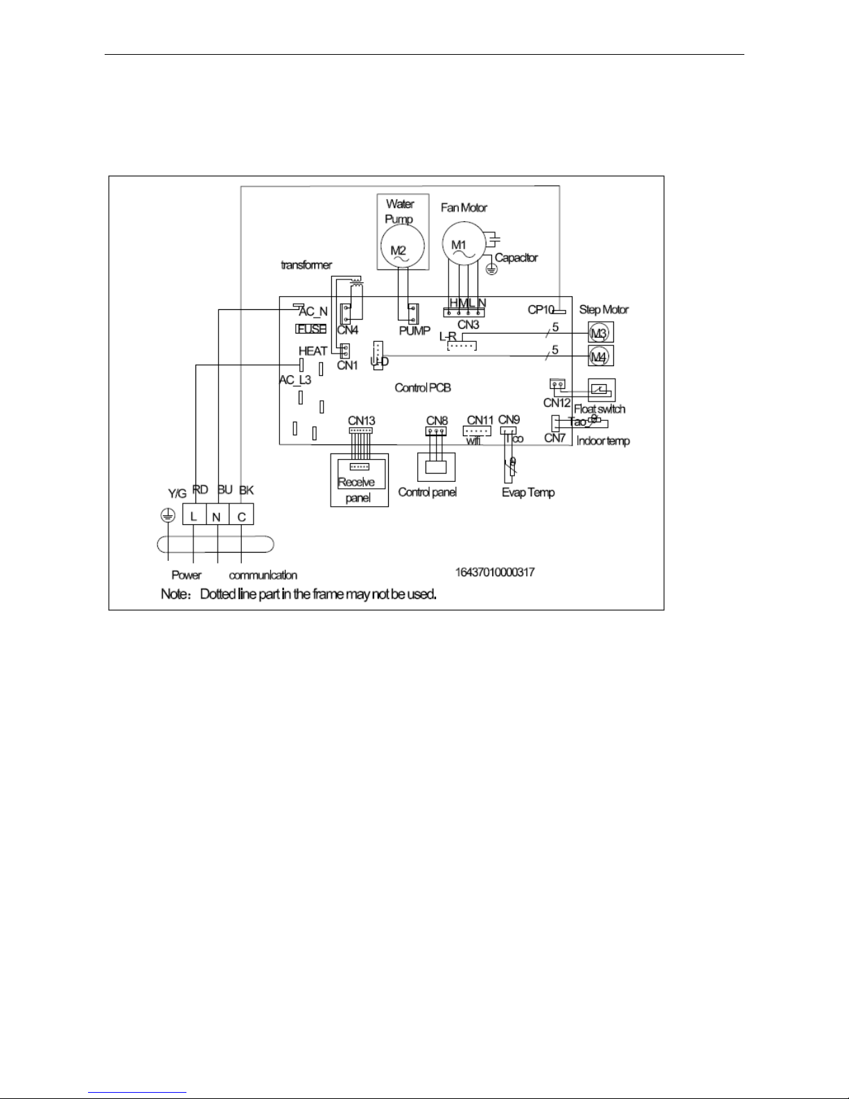
5. Electrical Diagram
AMCF-H09/4R1, AMCF-H12/4R1, AMCF-H18/4R1
AUX DC Inverter Free Match 50HZ R410A Ceiling & Floor Type
30
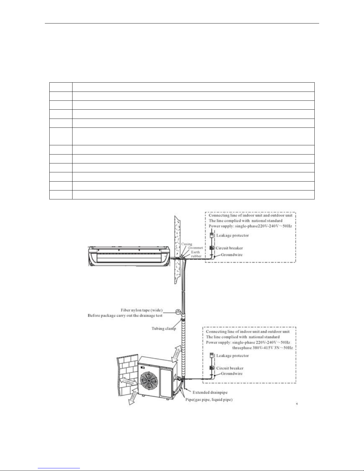
6. Installation
6.1 Preparation and equipments before installation
6.1.1Please buy following spare parts from your local market before installation
1
Hung bolts M12, 4 pcs
2
Drainage pipe PVC
3
Copper pipe
4
Adhesive belt (big size) 5 pcs, (small size) 5 pcs
5
Heat insulation material used to connect copper pipe (PE foam material, its thickness is more than 8mm)
6
Power cable, electrical wire between indoor and outdoor unit(Must be in accordance with the wire diameter
in the wiring diagram)
7
Acetylene cylinders, oxygen cylinders (when longer pipe used it should be welded)
8
One set pipe cut machine. (cut copper pipe)
9
Refrigerant cans, electronic balance (when longer pipe used additional gas should be charged)
10
Pressure gauges, pipe clamp, welding torch, 2B silver electrode
11
Wrench 2 pcs, one of them is with adjustable torque wrench(42N.m,65N.m,100N.mm)
12
Nitrogen cylinder (in order to prevent oxidation when welding, using Nitrogen to replace the air)
6.2 Installation drawing
 Loading...