

AuviTran AVM500-ES User Manual
AVM500-ES User’s Manual
1

AVM500-ES User’s Manual
2
FCC INFORMATION (U.S.A)
This device complies with Part 15 of the FCC rules.
Operation is subject to the following two conditions:
1. This device may not cause harmful
interference.
2. This device must accept any interference
received including interference that may cause
undesired operation.
1. IMPORTANT NOTICE: DO NOT MODIFY THIS UNIT!
This product, when installed as indicated in the
instructions contained in this manual, meets FCC
requirements. Modifications not expressly approved by
Yamaha may void your authority, granted by the FCC, to
use the product.
2. IMPORTANT: When connecting this product to
accessories and/or another product use only high quality
shielded cables. Cable/s supplied with this product MUST
be used. Follow all installation instructions. Failure to
follow instructions could void your FCC authorization to
use this product in the USA.
3. NOTE: This product has been tested and found to
comply with the limits for a Class B Digital device,
pursuant to Part 15 of the FCC Rules. These limits are
designed to provide reasonable protection against
harmful interference in a residential environment. This
equipment generates, uses and can radiate radio
frequency energy and, if not installed and used according
to the instructions found in the users manual, may cause
interference harmful to the operation of other radio
communications. Compliance with FCC regulations does
not guarantee that interference will not occur in all
installations. If this product is found to be the source of
interference, which can be determined by turning the unit
“OFF” and “ON”, please try to eliminate the problems by
using one of the following measures:
Relocate either this product or the device that is being
affected by the interference.
Utilize power outlets that are on different branch (circuit
breaker or fuse) circuits or install AC line filter(s).
In the case of radio or TV interference, relocate/reorient
the antenna. If the antenna lead-in is 300 ohm ribbon
lead, change the lead-in to co-axial type cable.
If these corrective measures do not produce satisfactory
results, please contact the local retailer authorized to
distribute this type of product. If you cannot locate the
appropriate retailer, please contact Yamaha Commercial
Audio Systems, Inc., Electronic Service Division, 6600
Orangethorpe Ave, Buena Park, CA90620.
The above statements apply ONLY to those products
distributed by Yamaha Commercial Audio Systems, Inc.
or its subsidiaries.
COMPLIANCE INFORMATION STATEMENT
(DECLARATION OF CONFORMITY PROCEDURE)
Responsible Party : Yamaha Commercial Audio Systems, Inc.
Address : 6600 Orangethorpe Ave.,
Buena Park, Calif. 90620
Telephone : 714-522-9011
Type of Equipment : EtherSound Network Matrix
Model Name : AVM500-ES
This device complies with Part 15 of the FCC Rules.
Operation is subject to the following conditions:
1) This device may not cause harmful interference, and
2) This device must accept any interference received including
interference that may cause undesired operation.
See user manual instructions if interference to radio reception is
suspected.

AVM500-ES User’s Manual
3
WARNING
Always follow the basic precautions listed below to avoid the possibility of serious injury or even death from
electrical shock, short-circuiting, damages, fire or other hazards. These precautions include, but are not limited
to, the followin
g
:
PRECAUTIONS
• Do not modify, open or disassemble the Product. The
guarantee shall be null and void in that case.
• Do not apply excessive pressure on connectors or
any other part of the board. Do not touch the metallic
sharp parts (pins) of the product.
• This product is electrostatic sensitive; make sure you
check this before touching or using it.
• The disconnect devices of the unit are the appliance
inlet of the auxiliary power supply and the appliance
inlet on the rear side of the unit. These must be easily
reachable.
• Conformity of this product is subject to proper
electrical wiring, regarding CEI364 (NFC15-100).
Installation must be equipped with differential
protection.
• To prevent electric shock, do not remove the cover.
No user-serviceable parts inside. This unit contains
hazardous voltages and should only be opened by a
trained and qualified technician. Both power supply
sources must be disconnected before servicing.
• Each connection must be Safety Extra Low Voltage
kind (SELV), and must stay inside buildings.
• FI: "Laite on liitettävä suojamaadoituskoskettimilla
varustettuun pistorasiaan"
• NO: "Apparatet må tilkoples jordet stikkontakt"
• SE: "Apparaten skall anslutas till jordat uttag"
• This product is designed to be rack-mounted. Be sure
to observe following installation rules of this kind of
equipment:
Elevated Operating Ambient - If installed in a
closed or multi-unit rack assembly, the operating
ambient temperature of the rack environment may be
greater than room ambient. Therefore, consideration
should be given to installing the equipment in an
environment compatible with the maximum ambient
temperature (Tma) specified by the manufacturer.
Reduced Air Flow - Installation of the equipment in a
rack should be such that the amount of air flow
required for safe operation of the equipment is not
compromised.
Mechanical Loading - Mounting of the equipment in
the rack should be such that a hazardous condition is
not achieved due to uneven mechanical loading.
Circuit Overloading - Consideration should be given
to the connection of the equipment to the supply
circuit and the effect that overloading of the circuits
might have on over current protection and supply
wiring. Appropriate consideration of equipment
nameplate ratings should be used when addressing
this concern.
Reliable Earthing - Reliable earthing of rackmounted equipment should be maintained. Particular
attention should be given to supply connections other
than direct connections to the branch circuit (e.g. use
of power strips).

AVM500-ES User’s Manual AuviTran 2010
4
ELECTRICAL AND ELECTRONIC INTERFERENCES RISKS
This Product uses high frequency digital circuits that
might interfere with electrical or electronic devices placed
in your working environment. Please make sure this kind
of device (television, radio device, cell phones) is
removed in order to ensure a proper functioning of each
device.
• Always use shielded cables and connectors (serial
port, word clock and EtherSound ports). In the other
case, AuviTran will not guarantee the proper behavior
of the product.
• Serial port cable must be length < 1m to ensure
proper EMC and interferences behavior.
• Word clock cable must be length < 1m to ensure
proper EMC and interferences behavior.
LIMITATION OF LIABILITY
In no case and in no way, the provider of this Product
(AuviTran, the distributor or reseller, or any other party
acting as provider) shall be liable and sued to court for
damage, either direct or indirect, caused by and to the
user of the board and which would result from an
improper installation or misuse of the Product. “Misuse”
and “improper installation” mean
installation and use not
corresponding to the instructions of this manual.
Please note that graphics given in this manual (drawings
and schemes) are only examples
and shall not be taken
for a real vision of your own equipment configuration.
AuviTran is constantly working on the improvement of the
products. For that purpose, the products functionalities
are bound to change and be upgraded without notice.
Please read carefully the User’s manual as the new
functionalities will be described therein.

AVM500-ES User’s Manual v2.1 AuviTran 2010
5
TRADEMARKS
All trademarks listed in this manual are the exclusive property of their respective owners. They are respected “as is” by
AuviTran. Any use of these trademarks must receive prior approval of their respective owners. For any question, please
contact the trademark’s owner directly.
COPYRIGHT
The information in this manual is protected by copyright. Therefore, reproduction, distribution of whole or part of this manual
is strictly forbidden without the prior written agreement of AuviTran.
AUVITRAN WEBSITE / MORE INFORMATION
Please visit our website for any question of further inquiry concerning our product range. Updates will also be posted when
available.
http://www.auvitran.com
PACKAGE CONTAINS
• 1 AVM500-ES
• 1 Power Cord
• 1 Safety Instructions Manual
L Cord-set with proper plug configuration must be used, depending on country in which the product is used

AVM500-ES User’s Manual v2.1 AuviTran 2010
6
TTAABBLLEE OOFF CCOONNTTEENNTTSS
1 WELCOME!............................................................................................................... 8
2 WHAT’S NEW?......................................................................................................... 8
3 TECHNICAL SPECIFICATIONS............................................................................... 9
4 REAR PANEL DESCRIPTION................................................................................ 10
5 TYPICAL ARCHITECTURE USING AVM500-ES .................................................. 10
6 POWERING AN AVM500-ES FOR THE FIRST TIME............................................11
6.1 Definition of Mono Network Mode..................................................................... 11
6.2 How to build a simple Star Architecture .............................................................12
6.2.1 Example #1 - NAI48-ES {ch1-16} to AVY16-ES100 {ch1-16}................................................................................... 15
6.2.2 Example #2 – AVY16-ES100 {ch13-16} to NXAmp {ch1-4}..................................................................................... 17
6.3 Why using Star Architecture instead of basic Dasy-Chain?....................................19
6.4 Limitations of the Mono Network Mode.............................................................. 21
6.4.1 Port {Aout} inactive ...................................................................................................................................................21
6.4.2 Remote control through 3rd Port – ES100/ESV2......................................................................................................21
7 SPLITTING NETWORKS FOR EXTENDED CAPACITIES....................................23
7.1 PM Multi Networks Mode – Hardware configuration.............................................. 23
7.1.1 Port {Aout} active....................................................................................................................................................... 24
7.1.2 Remote control through 3rd Port – ES100/ESV2......................................................................................................24
7.2 Generic Multi Networks Mode – Software configuration......................................... 25
7.2.1 Definition of the generic Multi Networks Mode.......................................................................................................25
7.2.2 Example of dissociated network..............................................................................................................................27
7.2.3 Building Ring Architecture .......................................................................................................................................29
7.3 Advanced Users: Multi Network Mode – Input configuration................................... 30
8 AVM500-ES IN ES-MONITOR SOFTWARE ..........................................................32
8.1 Software Installation...................................................................................... 32
8.2 Getting Started with AVM500-ES and ES-Monitor Software.....................................32
8.3 AVM500-ES Properties Page in ES-Monitor......................................................... 33
8.4 AVM500-ES Matrix Page in ES-Monitor .............................................................. 34
8.5 AVM500-ES Control Page in ES-Monitor............................................................. 37
8.5.1 Status box................................................................................................................................................................... 37
8.5.2 Port Configuration box..............................................................................................................................................38
8.5.3 Port A – EtherSound Channel Direction box........................................................................................................... 38
8.5.4 Clock Control box...................................................................................................................................................... 39
8.5.5 Tunneling Setup box ................................................................................................................................................. 39
8.5.6 Serial Port Configuration box...................................................................................................................................39
9 TUNNELING – GENERAL INFORMATION............................................................40

AVM500-ES User’s Manual v2.1 AuviTran 2010
7
9.1
Ex. 1: Communication between AVY16-ES100 and Serial Port................................. 40
9.1.1 AVY16-ES100 is plugged on port B.......................................................................................................................... 40
9.1.2 And if AVY16-ES100 is plugged on another port?.................................................................................................. 41
9.2 Ex. 2: Multiple tunneling – Port dissociation ....................................................... 42
10 SERIAL PORT INTERPRETER.............................................................................. 44
10.1 Enable Interpreter mode ................................................................................. 44
10.2 System architecture and conventions................................................................ 45
10.3 Programming interface................................................................................... 45
10.3.1 Get serial protocol version ....................................................................................................................................... 45
10.3.2 Set output patch......................................................................................................................................................... 46
10.3.3 Mute output ................................................................................................................................................................ 46
10.3.4 UnMute output............................................................................................................................................................ 46
10.3.5 Get output patch........................................................................................................................................................47
10.3.6 Patch example with Tera Term ®.............................................................................................................................. 48
11 ASIO CONFIGURATION ........................................................................................49
11.1 Enable ASIO mode ........................................................................................ 49
11.2 Disable ASIO mode .......................................................................................50
11.3 Play and Record with an ASIO port ................................................................... 50
12 AUXILIARY POWER SUPPLY............................................................................... 52
13 FIRMWARE UPDATE.............................................................................................52

AVM500-ES User’s Manual v2.1 AuviTran 2010
8
1 WELCOME!
Thank you for purchasing AuviTran’s AVM500-ES. We hope you will enjoy using it. This product will help you in expanding
your current EtherSound networks.
As AVM500-ES acts as an EtherSound matrix router, you will be able to handle up to 320 EtherSound channels linked to 5
physical ports, build ring redundancy topology, and many others architectures. AVM500-ES is able to aggregate separated
ES V2 and ES100 networks.
You will find herewith the necessary instructions to use your product. Please read them carefully as misuse of this device
might cause serious damage to you and your environment.
2 WHAT’S NEW?
This version of the manual refers to the last firmware of the AVM500-ES, i.e. version 0x110C / 0x118C. You are invited to
check the version of your device, and perform a firmware update if necessary.
Thanks to this new firmware, AVM500-ES has the following extended functionality:
-
AVM500-ES is now available as AVM500-ES/3ports, with all the advantages of AVM500-ES, limited to 3
EtherSound port
s, at a very attractive cost. AVM500-ES/3ports stays upgradable to regular AVM500-ES.
- Serial Port embedded a command interpreter that allows you to patch the whole matrix through a simple RS232
protocol. Please refer to dedicated paragraph for more information.
- Device ports C, D and E can be swapped from EtherSound to ASIO protocol. ASIO computer-based application
will be able to play/record up to 64 channels on each port. Matrix patch allows choosing which channel is to be
played or recorded. You will find more information in the dedicated paragraph.

AVM500-ES User’s Manual v2.1 AuviTran 2010
9
3 TECHNICAL SPECIFICATIONS
General
Size 483 x 253 x 44mm (19’ rack / 1U Height)
Power Consumption <50 Watts
Main Power Supply 100-240VAC 50/60Hz 1.5A Max
DC supply (Auxiliary) 5Vdc 5A max – 12Vdc 2A max
Auxiliary Power Supply 100-240V~ 47-63Hz 1.35A / +5Vdc 5A ; +12Vdc 2A
Storage: Temp/Humidity - 5°C to 70°C / Max 95% (non-condensing)
Operating: Temp/Humidity 5°C to 40°C / 5% to 90% (non-condensing)
Front Panel Networks and links Rx and Tx Activities; Active synch running ; Power Main, Aux and On Display
Rear Panel 1 IEC Power inlet; 7 Neutrik EtherCon RJ45; 1x6 poles Euroblock Connector for Aux power supply; 1 BNC for word
clock synch in; 1 DB9 connector for Serial Port
AVM500-ES Features
EtherSound Network Segment 5 EtherSound Net work Segments interconnections : A (In, Out), B, C, D, E
EtherSound IN Port 1 EtherSound IN Port: AIN
EtherSound OUT Port 5 EtherSound OUT Ports: AOUT, B, C, D and E
ES-100 to ES-100 Latency 6 samples (125µs at 48 kHz)
Digital Audio Channels 320 (5 x 64) Input Audio channels and 320 (5 x 64) Output Audio channels
Matrix / Patch size 320x320 full cross matrix with remote control patch via EtherSound
Any individual output audio channel can be muted or patched to any of the 320 available Input audio channels
Remote control Via EtherSound of from Ethernet PC remote link
Other I/O RS232 serial port
Clock Synchronisation mode 48 kHz local clock (when Primary Master) or EtherSound Network (When not PM)
Word clock In used for synchronisation
Temp / Fan monitoring
Temp Monitoring Network Monitoring of Temperature inside the Box
PSU Monitoring Network Monitoring of PSU Failure for Main and Aux power supply
2 Fan Control modes Automatically Controlled by internal Temperature
Off
Development and Integration Environment
OS Supported Windows XP
ES-Monitor ES-Monitor enables to remotely set, control and monitor an EtherSound network and provides enhanced property
pages to manage the AVM500-ES specific parameters.
Remote Network Management Links status, Power supply status (Main, Aux), Temperature monitoring , Fan remote control and PSU Aux/Main
remote control
Rear Panel Description – Typical architecture
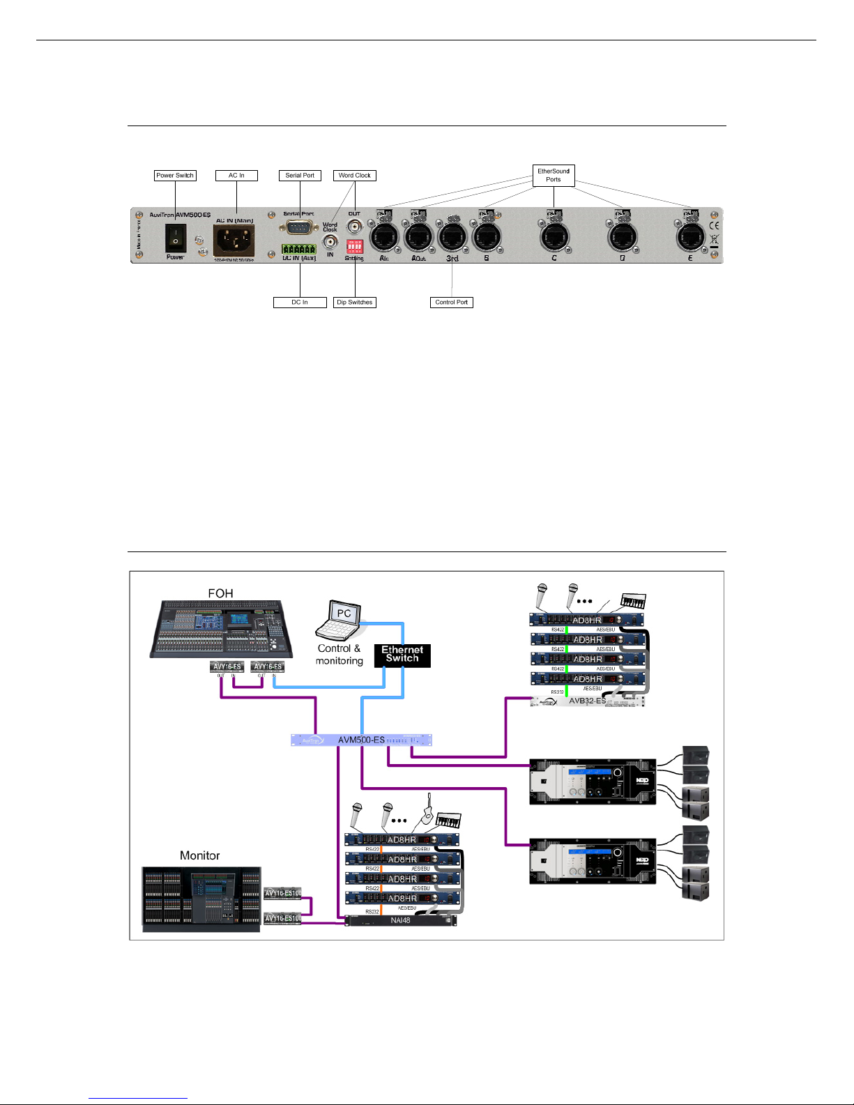
4 REAR PANEL DESCRIPTION
2- Power switch : switch on or off the main power supply
3- AC IN : main power supply. Refer to tech specs for AC range
4- DC IN : auxiliary power supply (described at the end of this document)
5- Dip switches : setup the device
6- Serial Port : standard RS232 for custom application
7- Word Clock : Input and Output for external synchronization
8- EtherSound Ports : link to EtherSound network (or control PC)
9- Control Port : connection to control PC only
5 TYPICAL ARCHITECTURE USING AVM500-ES
This is an example of the AVM500-ES capability: each cluster of EtherSound devices can share up to 64 audio channels with
each others, in bidirectional configuration. With ES100 networks, control PC can be plugged directly to AVM500-ES “3
rd
port”
to control the whole network.
AVM500-ES User’s Manual v2.1 AuviTran 2010
10
Powering an AVM500-ES for the first time
6 POWERING AN AVM500-ES FOR THE FIRST TIME
AVM500-ES is a dedicated and versatile EtherSound network router and matrix. Many configurations and parameters are
available to best fit each kind of architecture you want to build. When powering an AVM500-ES for the first time, it will boot in
the factory configuration. This mode is called “Mono network mode”. This is the simplest way to use an AVM500-ES.
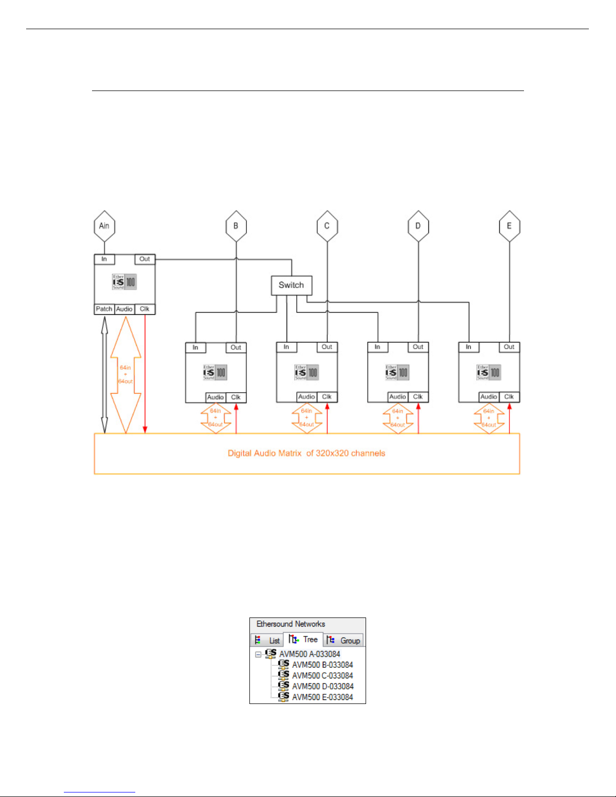
6.1 Definition of Mono Network Mode
To be more efficient when using your AVM500-ES, you need to understand how it is build. If you have a look to the Fig. 1,
you will see how the AVM500-ES behave when in the Mono Network mode, from EtherSound point of view.
Fig. 1: Simplified view of AVM500-ES behavior
AVM500-ES acts as 5 EtherSound devices, with smart interconnections
From a network point of view, {Ain} is an EtherSound input port. The output port of the related device is connected to the 4
others device’s input ports, through a regular switch.
Doing so, {B, C, D, E} ports are EtherSound output ports. From a hierarchic point of view, {B, C, D, E} are behind {Ain}
(see Fig. 2).
All 64in channels + 64out channels of each device are always connected to the 320x320 digital audio matrix, at any time.
Audio clock for synchronization is coming from {Ain} port and distributed to {B, C, D, E} ports. This is always true, whatever
the configuration of the AVM500-ES.
Audio patch of the 320x320 digital audio matrix is only available through {Ain} port.
Fig. 2: Tree view in Mono Network Mode
AVM500-ES User’s Manual v2.1 AuviTran 2010
11
Powering an AVM500-ES for the first time
To sum-up theses points, we can compare AVM500-ES to an EtherSound device with one input port and four output ports.
hese four ports are always synchronized to the input port. Each port can share its audio channels with each other.
de allows you to build bidirectional star architecture that was absolutely impossible to do before, with a regular
itch.
th an AVM500-ES in Mono Network Mode. Audio
atch will also be detailed here to help you handle the device step by step.
pposite. The node “concentrates” multiple branches in a single one. The AVM500-ES is this node.
T
This mo
sw
.2 H6 ow to build a simple Star Architecture
You will find herewith all the procedure to build your first star architecture wi
p
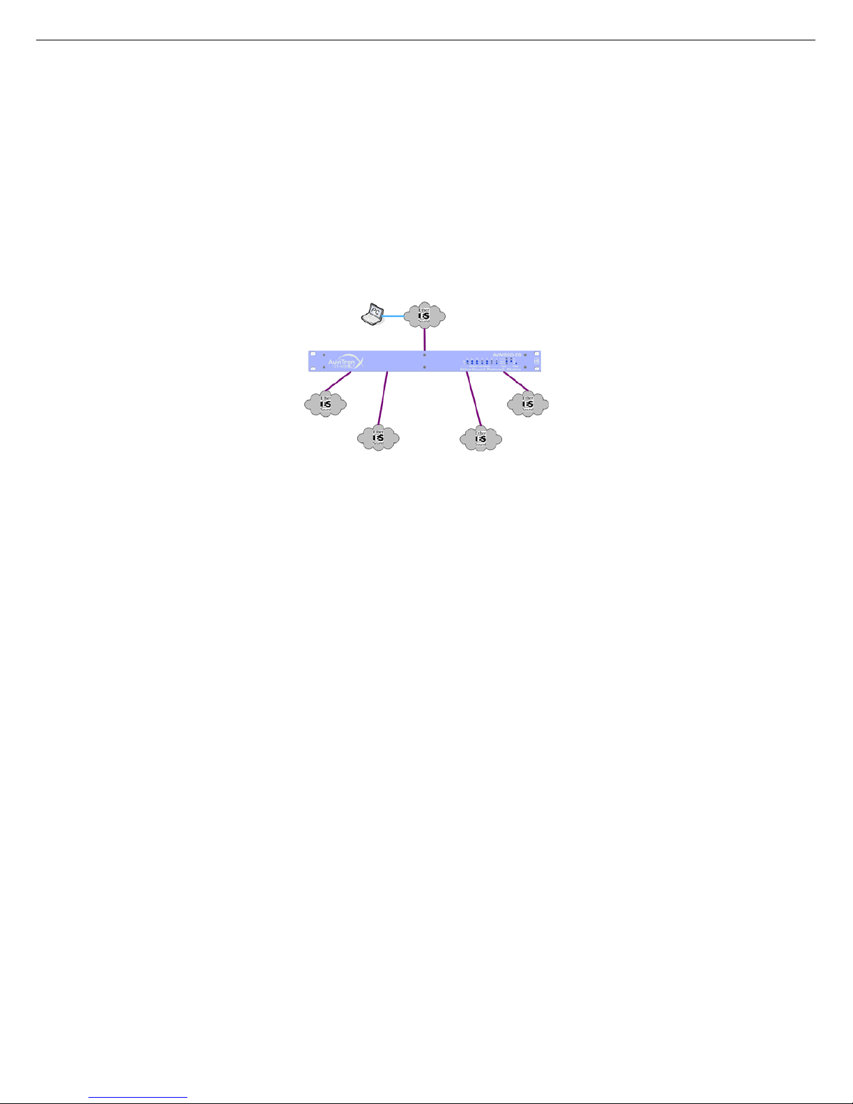
Fig. 3 illustrates what we call a star architecture. In few words, a star architecture has a “node” that acts as a splitter. This is
a point where a network is divided in multiple branches. This vision is true for the downstream. For the upstream, this is the
o
Fig. 3: Star architecture
d network using an AVM500-ES, and how to use the
etpatch to route audio channels. Let’s have a look to the schematic:
In the following example, you will learn how to build a real EtherSoun
N
AVM500-ES User’s Manual v2.1 AuviTran 2010
12
Powering an AVM500-ES for the first time
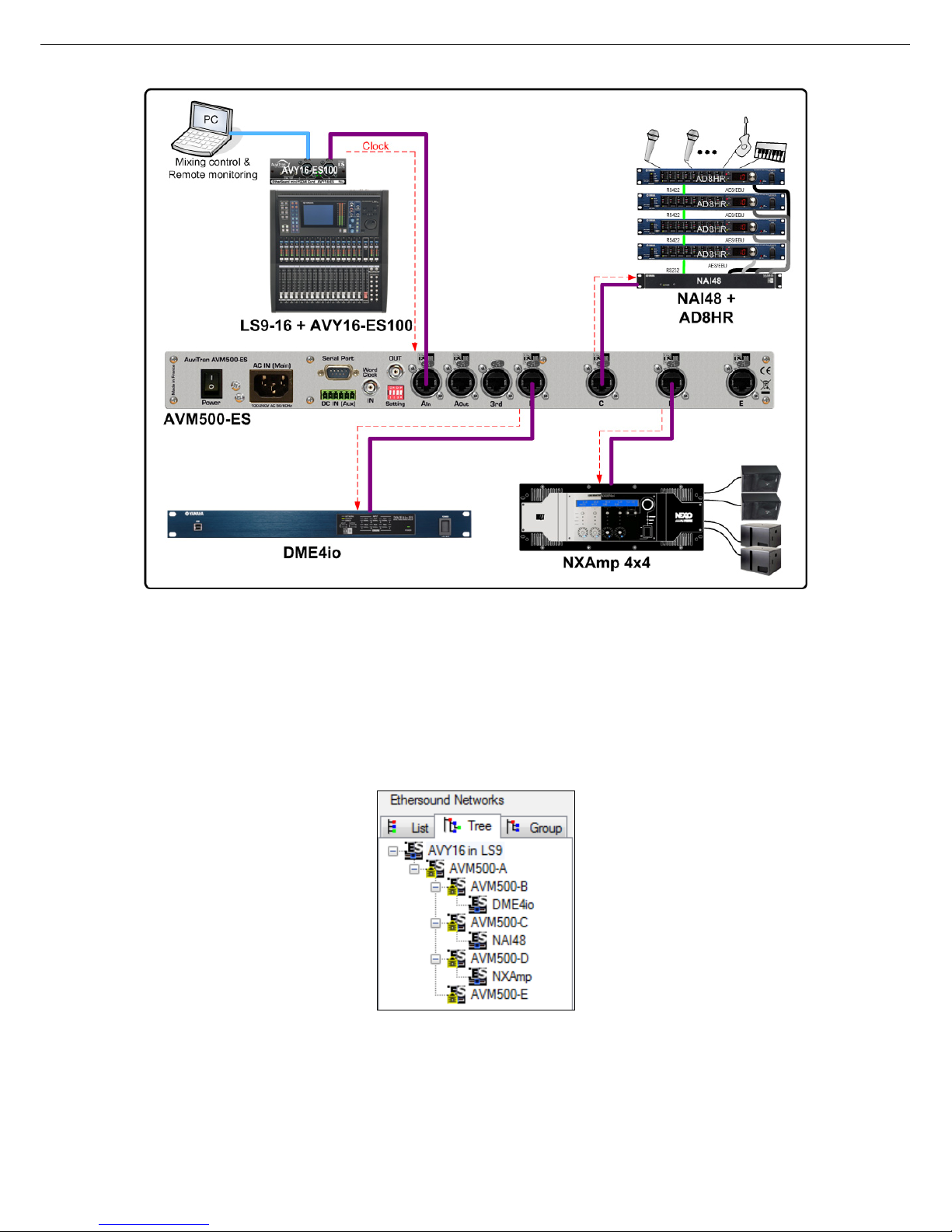
Fig. 4: Example of architecture
In this network, the AVY16-ES100 in the LS9 mixing console is the Primary Master (PM). Indeed, there is no EtherSound
network plugged on its In port, but only the control PC. The Out port of the AVY16-ES100 is connected to port {Ain} of the
AVM500-ES. Ports {B, C, D}, that are Outputs ports, are connected respectively to port In of DME4io, NAI48-ES and NXAmp
4x4. Port {E} is unused.
Remember that in this example, the AVY16-ES100 is PM, so it generates the audio clock. This clock is transmitted to the
AVM500-ES port {Ain} through EtherSound. As described in the previous paragraph, AVM500-ES propagates the clock from
{Ain} to {B, C, D, E}, so the three third-party devices are properly feed with clock.
When running AuviTran ES-Monitor software on the control PC, the Tree View of this network will be the following:
Fig. 5: Hierarchy view of example architecture
The AVY16-ES100 is obviously the Primary Master, followed by port {Ain} of the AVM500-ES. Ports {B, C, D, E} are on the
same hierarchy level, as expected. And behind each port, we can find our three EtherSound devices.
AVM500-ES User’s Manual v2.1 AuviTran 2010
13
Powering an AVM500-ES for the first time
L The following description of Netpatch is based on version 3.9.3 of ES-Monitor software,
which is the official released version at the time where this manual is written.
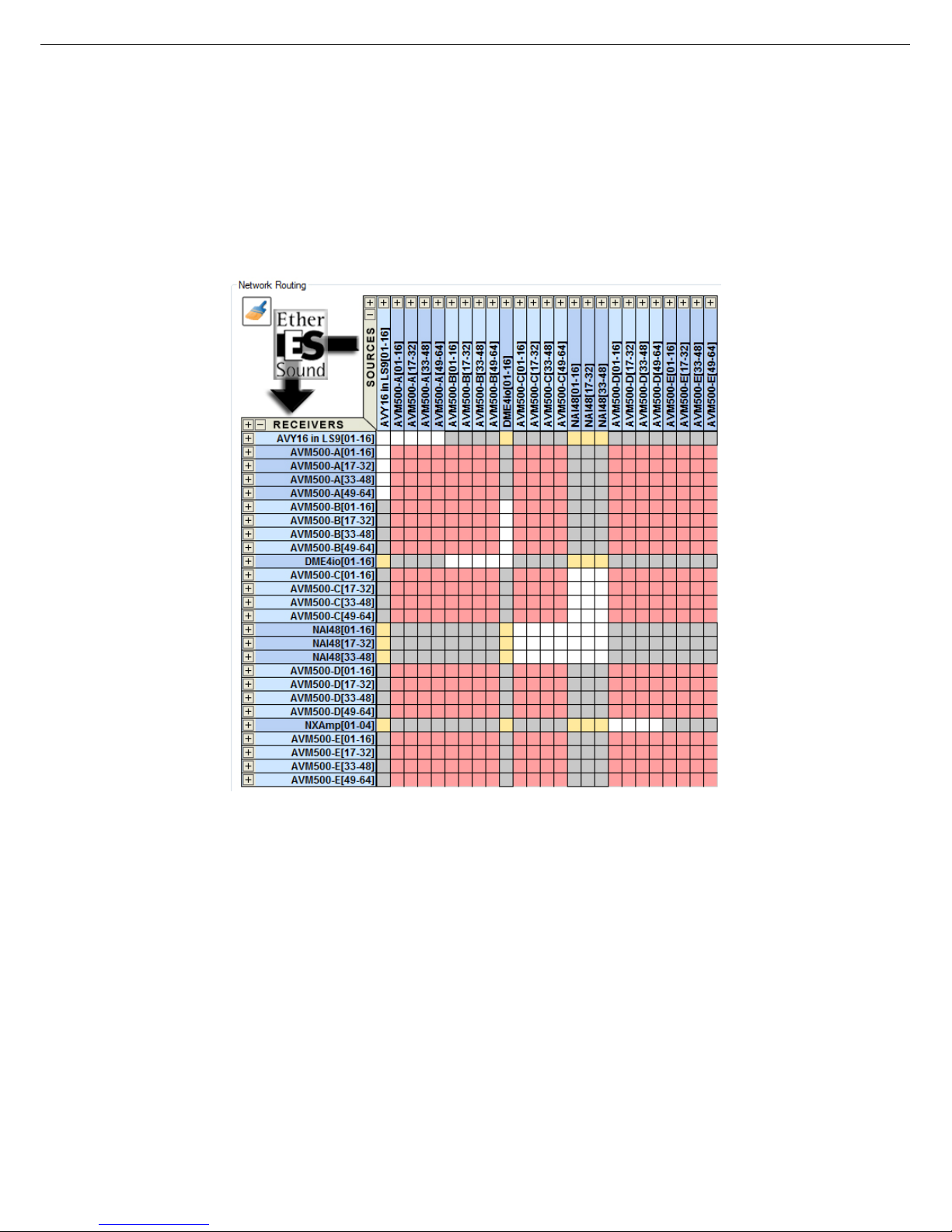
Let’s have a look to the Netpatch now. We can see four different colours in it:
- White, means you can make a direct connection between source and destination.
- Gray, means there is no way to make a direct connection.
- Pink, means this is the matrix internal patch of an AVM500-ES.
- Yellow, means that there is a possible path through an AVM500-ES.
Fig. 6: NetPatch view of example architecture
In this example, you will learn how to make the following patch:
(1) NAI48-ES {ch1-16} to AVY16-ES100 {ch1-16}
(2) AVY16-ES100 {ch13-16} to NXAmp {ch1-4}
Since version 3.9.3 of ES-Monitor software, such a path is now extremely easy using net patch. It is a “one click” process.
AVM500-ES User’s Manual v2.1 AuviTran 2010
14

Powering an AVM500-ES for the first time
6.2.1 Example #1 - NAI48-ES {ch1-16} to AVY16-ES100 {ch1-16}
If you want to route NAI48-ES channels directly to AVY16-ES100 inputs, you will see that you are facing a yellow cell. This
means that Netpatch found a connection between theses two devices through an AVM500-ES. As patch grid is collapsed 16
by 16 in this example, all you have to do is to click the yellow cell between NAI48 {ch1-16} and AVY16 {ch1-16}. The
software will do everything automatically!
Fig. 7: First step patch
The patch you’ve just made in yellow cell is represented by a star. This is the symbolic view for a patch through an AVM500ES. At the same time, Netpatch added the real path of audio channels:
- One cross (direct connection) between NAI48 and AVM500-ES Port C.
- One circle (AVM500 internal patch) between Port C and Port A.
- One cross (direct connection) between Port A and AVY16-ES100.
Now, if you select AVM500-ES port {Ain}, and then you go to the “Matrix” tab, you will notice that internal digital audio matrix
was effectively patched as expected.
AVM500-ES User’s Manual v2.1 AuviTran 2010
15

Powering an AVM500-ES for the first time
Fig. 8: First step automatic Matrix patch
AVM500-ES User’s Manual v2.1 AuviTran 2010
16
 Loading...