

AuviTran AVDT-BOB-AE810, AVDT-BOB-AE410, AVDT-BOB-AS810, AVDT-BOB-ADX810, AVDT-BOB-ADE810 User Manual
AVDT-BOB User’s manual v1.3 Page 1 / 25
AVDT-BOB
User’s manual
www.auvitran.com
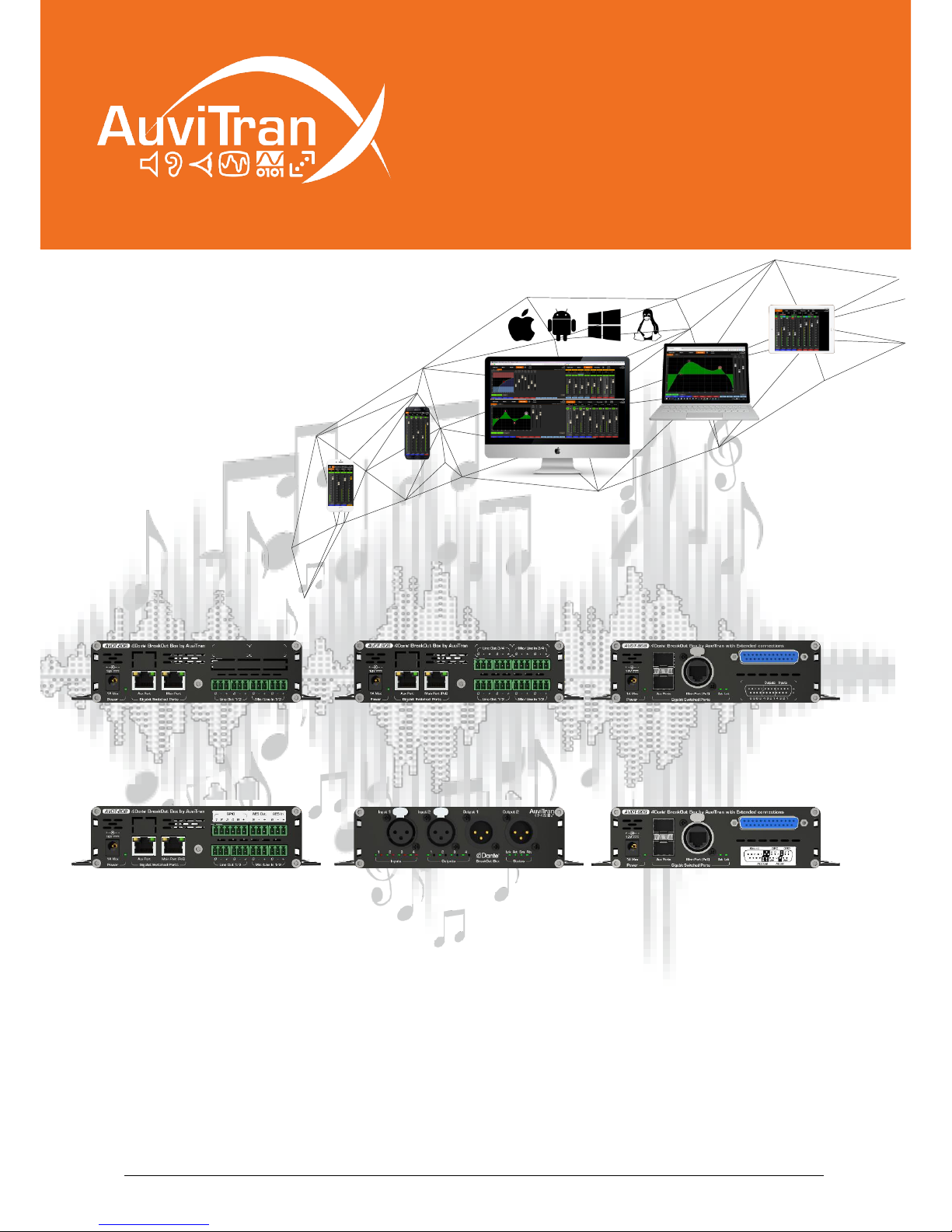
AVDT-BOB-AE4IO
AVDT-BOB-AE8IO
AVDT-BOB-AS8IO
AVDT-BOB-ADE8IO
AVDT-BOB-ADX8IO (Front)
AVDT-BOB-ADX8IO (Rear)

AVDT-BOB User’s manual v1.3 Page 2 / 25
Table of contents
1. Legacy ............................................................................................................... 3
1.1 LIMITATION OF LIABILITY .............................................................................3
1.2 TRADEMARKS .............................................................................................3
1.3 COPYRIGHT .................................................................................................3
1.4 MORE INFORMATION ...................................................................................3
2 AVDT-BOB Quick Start ........................................................................................ 4
2.1 Power to Start-up .........................................................................................4
2.2 Connect the AVDT-BOB to an IP/Dante network ...............................................4
2.3 AVDT-BOB’s Dante settings ...........................................................................5
2.4 Access to AVDT-BOB’s User Interface via AVSMonitor on Windows OS ..............6
2.5 Access to AVDT-BOB’s User Interface via a Browser ........................................7
3 AVDT-BOB architecture ....................................................................................... 8
3.1 AVDT-BOB inputs and outputs ........................................................................8
3.2 AVDT-BOB architecture ................................................................................8
3.3 AVDT-BOB’s schematic .................................................................................9
3.4 Input processing block .................................................................................. 10
3.5 Mixing Processing block ............................................................................... 11
3.6 Output processing block ............................................................................... 11
4 AVDT-BOB User’s Interface ............................................................................... 12
4.1 Bar menu for interface selection ................................................................... 12
4.2 Inputs interface .......................................................................................... 12
4.3 Mixers’ interface ......................................................................................... 13
4.4 Outputs’ interface ....................................................................................... 14
4.5 Processing interface .................................................................................... 15
4.5.1 EQ Processing view ............................................................................... 16
4.5.2 Limiter/Compressor view ........................................................................ 17
4.6 Parameter interface .................................................................................... 18
4.6.1 General software setting menu ............................................................... 18
4.6.2 Network parameters menu ..................................................................... 18
4.6.3 Save/Load parameter menu .................................................................... 19
4.6.4 GPIO menu (available for AVDT-BOB-ADE8IO/ADX8IO ............................... 20
4.6.4.1 GPIO in GPI Mode ........................................................................... 21
4.6.4.2 GPIO in GPO Mode .......................................................................... 22
4.6.4.3 GPIO in Fader Mode ........................................................................ 23
5 GPIO wiring for AVDT-BOB-ADE8IO or AVDT-BOB-ADX8IO ................................... 24
5.1 GPIO Connection for “GPI” mode ................................................................... 24
5.2 GPIO Connection for “GPO” mode ................................................................. 25
5.3 GPIO Connection for “Fader” mode ................................................................ 25

AVDT-BOB User’s manual v1.3 Page 3 / 25
1. Legacy
1.1 LIMITATION OF LIABILITY
In no case and in no way, the provider of this software (AuviTran, the distributor or reseller,
or any other party acting as provider) shall be liable and sued to court for damage, either
direct or indirect, caused to the user of the software and which would result from an improper
installation or misuse of the software. “Misuse” and “improper installation” mean installation
and use not corresponding to the instructions of this manual.
AuviTran is constantly working on the improvement of the products. For that purpose, the
products functionalities are bound to change and be upgraded without notice. Please read
carefully the User’s manual as the new functionalities will be described therein.
1.2 TRADEMARKS
All trademarks listed in this manual are the exclusive property of their respective owners.
They are respected “as is” by AuviTran. Any use of these trademarks must receive prior
approval of their respective owners. For any question, please contact the trademark’s owner
directly.
1.3 COPYRIGHT
The information in this manual is protected by copyright. Therefore, reproduction, distribution
of whole or part of this manual is strictly forbidden without the prior written agreement of
AuviTran.
1.4 MORE INFORMATION
Please visit our website for any question of further inquiry concerning our product range.
Updates will also be posted when available.
http://www.auvitran.com
AVDT-BOB User’s manual v1.3 Page 4 / 25
2 AVDT-BOB Quick Start
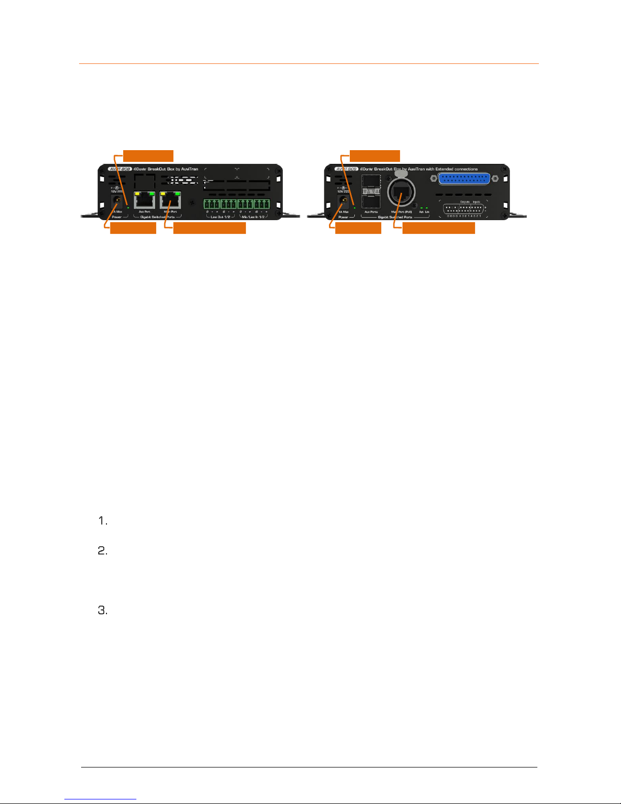
2.1 Power to Start-up
To start your AVDT-BOB, connect the Main port of your AVDT-BOB, to an active POE switch
port using a CAT5E/6 cable (Gigabit connection) or alternatively connect an optional 12V DC
power to the DC Power connector of your AVDT-BOB.
POE Port (Main)DC Plug
Power LED Power LED
POE Port (Main)DC Plug
When powered, the Green Power led of the AVDT-BOB will be On.
Notice: You can use at the same time the POE and 12VDC and they will act as redundant
power supplies.
2.2 Connect the AVDT-BOB to an IP/Dante network
The connection of your AVDT-BOB to the IP/Dante network can done via Ethernet CAT5e/6/7
cables using the Main Gigabit port that is POE compatible or via the Aux Gigabit port(s)
When connected to another active/running Ethernet device (Switch, Mac, PC, IP router), the
Link LED of the connected port will be On and the Act LED will start flashing.
AVDT-BOB can be daisy chained to other Dante device via the remaining port(s) thanks to an
internal gigabit switch that connects:
- Physical Ethernet ports (Main, Aux)
- Dante component
- User Interface of ARM processor managing Web 2.0, DSP and Mic preamps
AVDT-BOB has 2x independent IP network addresses and 2 associated names to control
“Dante” functions and “User-Interface”:
IP addresses are set automatically by default via a DHCP server or using APIPA
addresses (169.254.xxx.xxx/16).
The Dante name of an AVDT-BOB may be changed by the Dante Controller. This name
is preset at factory at “AVDT-BOB-#” where # is its serial number.
AVDT-BOB serial number 145 has Dante name “AVDT-BOB-145” as
factory preset.
The name of User Interface of an AVDT-BOB is its Dante name plus a fixed extension
“-UI”. This name is preset at factory to “AVDT-BOB-#-UI” where # is its serial number.
AVDT-BOB with serial number 145 has User Interface name “AVDT-BOB-
145-UI” as factory preset.

AVDT-BOB User’s manual v1.3 Page 5 / 25
2.3 AVDT-BOB’s Dante settings
The AVDT-BOB Dante settings are done via the standard Audinate Dante Controller.
Download Dante Controller on the Audinate web site at the following web address
https://www.audinate.com/products/software/dante-controller
Install Dante Controller by double clicking on the download file.
Start Dante Controller to detect your AVDT-BOB Dante devices and control settings
To change AVDT-BOB name, Double click on the device label
Select “Device Config” tab in the new windows and modify the “Rename Device” field
Consult the Audinate Dante Controller User’s manual for any other information

AVDT-BOB User’s manual v1.3 Page 6 / 25
2.4 Access to AVDT-BOB’s User Interface via AVSMonitor on Windows OS
The AVDT-BOB User Interface can be accessed using AVSMonitor on Windows OS:
Download AuviTran AVS-Monitor free software for windows 7/8/10 available at the
following web address http://www.auvitran.com/w4/?page_id=86
Install AVS-Monitor by double clicking on the download file.
Start AVS-Monitor.
The AVDT-BOB connected to the network will automatically appears in 2 lists on left:
▪ “Network controller” provides access to the AVDT-BOB control
▪ “Dante Network” give “Dante” information on the AVDT-BOB
Select the AVDT-BOB in the left list called “Network controller” and” “Control” Tab in
the right windows as describe bellow.
See chapter 3 for interface description.
Notices:
- If your device doesn’t appear, your network configuration is probably not good.
1) Go to the AVS-Control-Panel using “Edit/Control panel” menu or press Ctrl+P
2) Select a valid network adapter in the “Dante / AuviTran Adapter”
3) Press the “Turn On” button if the service is off (red LED).
- The “Properties Tab” provides the IP address of the AVDT-BOB user’s interface
- You can transfer the control of your device to
your standard browser by a right click on AVDTBOB name in the Network list and selected “Open
on new window”
- For more information on AVSMonitor read its “User’s manual”
AVDT-BOB User’s manual v1.3 Page 7 / 25
2.5 Access to AVDT-BOB’s User Interface via a Browser
The user interface of an AVDT-BOB can be launched without installation by any standard Web
browser compatible with HTML5 and JavaScript standards.
The device hosting the web browser must comply with the following:
- May be any platform PC, Laptop, Tablet, Smartphone working whatever OS (MacOS,
iOS, Android, Windows, Linux …) with a minimum resolution of 800x600 or
600x800
- Must be connected to the same IP network than the AVDT-BOB to control it
- It can use WIFI or Ethernet link
To launch the user interface of an AVDT-BOB using a browser
Start a Web Browser (i.e. Safari, Firefox, Chrome, Opera…)
Write the User Interface Name (see §2.2) terminated by “.local” in Web Browser
address field/bar to ask it accessing to the IP server with a local name in your local
area network (“.local” at the end is needed to force mDNS local name in the browser)
“AVDT-BOB-145-UI.local” for instance to connect to AVDT-BOB serial
number 145 if the Dante name was not changed
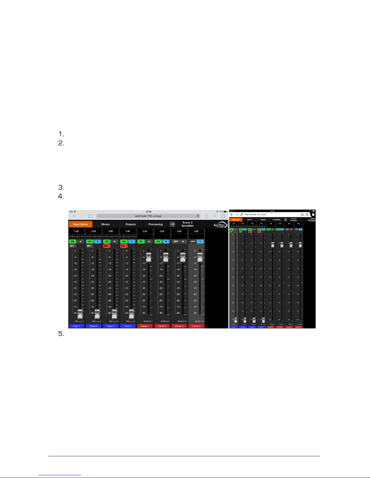
The Browser will display AuviTran’s Logo during the loading of the user’s interface.
After loading you will see the interface of the AVDT-BOB User interface as Follows
(iPad/Safari and iPad/Firefox).
See chapter 3 for a description of the AVDT-BOB User’s interface.
Notices:
- IE and Edge on Windows OS does not manage the “.local” and mDNS name. Use the
IP address of the User’s Interface for this web Browser or follow instructions given
in §2.4 notices to run web browser directly from AVSMonitor.
- If you have problem with the UI name, remember you can change it using Dante
controller.

AVDT-BOB User’s manual v1.3 Page 8 / 25
3 AVDT-BOB architecture
3.1 AVDT-BOB inputs and outputs
The AVDT-BOB-AE8IO and AVDT-BOB-AS8IO have 4 analog balanced Mic/Line inputs and 4
balanced analog outputs on Euroblock/SUBD connectors. They can receive and send 4 digital
signal from/to Dante from their Main or Aux gigabits Ethernet ports.
The AVDT-BOB-AE4IO has {2} analog balanced Mic/Line inputs and {2} balanced analog
outputs on Euroblock connectors. It can receive and send 4 digital signal from/to Dante from
its Main or Aux gigabits Ethernet ports.
These input / output signals are named as follows in these AVDT-BOB:
- Mic/Line1-4{2} for the signals coming from Mic/Line inputs
- Dante In1-4 for the signals coming from Dante network
- Line Out1-4{2} for the signals sending to Line outputs
- Dante Out1-4 for the signals sending to Dante network
The AVDT-BOB-ADE8IO and AVDT-BOB-ADX8IO have 2 analog balanced Mic/Line inputs +
an AES/EBU input and 2 balanced analog outputs + an AES/EBU output on
Euroblock/XLR/SUBD connectors. They can receive and send 4 digital signal from/to Dante
from their Main or Aux gigabits Ethernet ports.
These input / output signals are named as follows in these AVDT-BOB:
- Mic/Line1-2 for the signals coming from Mic/Line inputs
- AES/EBU ch1-2 for the signals coming from AES/EBU input
- Dante In1-4 for the signals coming from Dante network
- Line Out1-2 for the signals sending to Line outputs
- AES/EBU ch1-2 for the signals sending to AES/EBU output
- Dante Out1-4 for the signals sending to Dante network
3.2 AVDT-BOB architecture
The AVDT-BOB architecture is divided in 3 main interconnected blocks:
- The Input block manages Mic/Line1-4{2} preamps, { ch1-2} and Dante in1-4.
It sends DirectOut MicLine1-4{2}, { ch1-2} to Output Processing Block. It
computes processed Mic/Line1-4{2], { ch1-2} and 4 processed Dante inputs
for the Mixing and Output Processing Blocks.
- The Mixing block receives the processed Mic/Line1-4{2}, { ch1-2} and
Dante1-4. It mixes them on 4 independent mixers to provide mixing Master1-4 to
Output Processing Block.
- The Output block enables selecting the source Out1-4{2}, { ch1-2} and
Dante Out1-4 from DirectOut Mic/Line1-4{2}, { ch1-2}, Processed
Mic/line1-4{2}, { ch1-2}, Processed Dante1-4 and the Master1-4. Once the
source selection done it processes Line and Dante outputs.
 Loading...