

AUVIO 40-290 User Manual
T H E P E R F O R M A N C E Y O U N E E D
TM
100W 2-Way
In-wall Speaker
User’s Guide 40-290
Please read this user’s guide before using your new speaker.
© 2009. Ignition L. P. All rights reserved. Auvio is a trademark used by Ignition L.P.
Package and insert are recyclable. Insert contains recycled material.

2
2
Package Contents
In-wall Speaker Template / Paint Mask
User’s Guide Quick Start
Features
Mount your speaker flush with the ceiling or wall with the
wing-type mounting system.
The frame and grille can be painted to match the room’s
decor.
The tweeter can be tilted to direct the sound to best suit
the room’s acoustics.
1 Installation
Prepare the location
To mount your speaker, you need the following items (not
supplied).
Drywall or keyhole saw
Wire stripper
Phillips screwdriver
Pencil or maker
18-20 gauge speaker wire
Be sure the mounting surface:
Is between 3/8 – 11/8 inch thick (9.5 – 32 mm)
Has at least 3 inches (76 mm) clearance behind the surface
Has no wall studs or other objects to block the back of
the speaker
w Warning: Be careful not to cut into existing wiring or
plumbing hidden behind the wall.
3
3
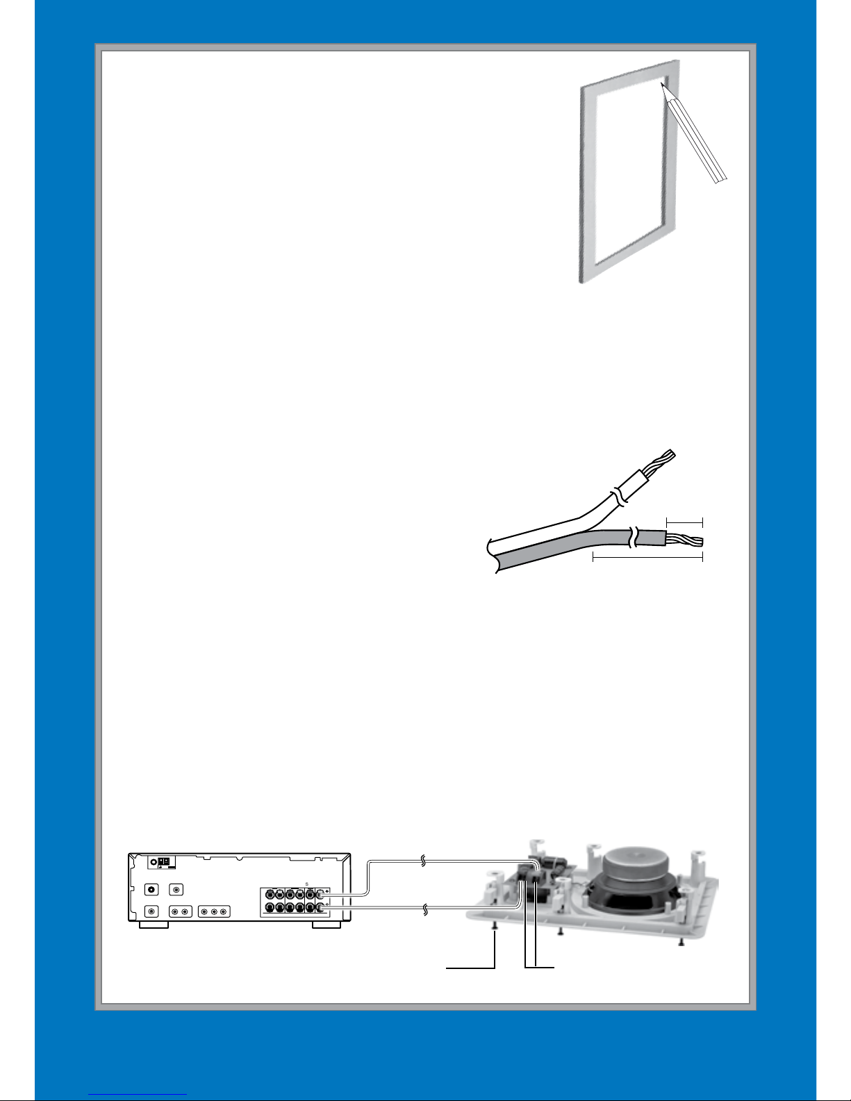
1. Remove the inner cardboard disc from
the supplied template/paint mask and
keep it for later. Use the outer portion
of the mask as a template to mark
the cutout hole size and location for
mounting the speaker.
2. Use a drywall or keyhole saw to cut
the hole.
2 Connect to your amplifier
1. Route the speaker wire from your amplifier to the
speaker. Avoid routing near existing electrical wires and
do not nail or staple the wire.
2. Separate about 4 inches (100
mm) of wire at each end.
3. Using a wire stripper, remove
about 1/4 inch (6 mm) of
insulation from each wire. Then
twist the ends of each wire.
4. Connect the positive (marked) wire to the red speaker
terminal by pressing the tab, inserting the wire into the hole,
and releasing the tab. Repeat this procedure to connect the
negative (unmarked) wire to the black terminal.
6. Connect the wire coming from the red terminal to your
amplifier’s positive (+) terminal. Connect the wire from
the black terminal to your amplifier’s negative (–) terminal.
Template
AM
LOOP
FM UNBAL
75
Ω
ANTENNA
FRONT
R
L
CENTERSURROUND
S
K
E
R
S
R
L
S-VIDEO cable Coaxial digital cable
Composite Video Cables Audio Cables Component Video Cables
SPEAKERS
Tabs
Screw
4 inches
1
/
4
inch
4 inches
1
/4 inch
 Loading...