

P-BS100/FE - Rev.F / Doc/ 980114 Autronica Fire and Security AS
BS-100 DYFI
Operators Handbook
Program Version P1-BS100-3-20
P5-BS100-3E20
Protecting environment, life and property...

BS100 DYFI Operators handbook
P-BS100/FE - Rev.F / Doc/ 980114 2 Autronica Fire and Security AS

BS100 DYFI Operators handbook
P-BS100/FE - Rev.F / Doc/ 980114 3 Autronica Fire and Security AS
Contents
Please note!
This handbook contains instructions for operation of fire alarm system BS-100 DYFI
ready designed and assembled from the factory.
If the system is to be expanded on site, please see separate handbooks covering internal
mounting and internal connections.
Page
1. Operating/control panel .......................................................................... 5
2. Prewarning ............................................................................................... 6
2.1 Indications on the control panel in the event of a "PREWARNING" 6
2.2 Actions to be taken in the event of a "PREWARNING"..................... 7
3. Fire alarm ................................................................................................. 8
3.1 Indications on the control panel in the event of a "FIRE" alarm ........ 8
3.2 Actions to be taken in the event of a "FIRE" alarm............................. 9
4. More alarms ........................................................................................... 11
4.1 Indications on the control panel in the event of “MORE ALARMS”11
4.2 Actions to be taken in the event of "MORE ALARMS" ................... 12
5. Fault ........................................................................................................ 14
5.1 Indications on the control panel in the event of “FAULT”............... 14
5.1.1 Indications at more (multiple) fault ............................................ 14
5.2 Actions to be taken at “FAULT” ....................................................... 15
6. Menu ....................................................................................................... 16
6.1 Menu structure ................................................................................... 16
6.2 Password protected functions ............................................................ 17
6.3 Menu operation .................................................................................. 18
6.4 "Main menu"...................................................................................... 19
7. Out / in - control..................................................................................... 20
7.1 Disable ............................................................................................... 20
7.1.1 Disable address ........................................................................... 21
7.1.2 Disable zone................................................................................ 22
7.1.3 Disable controls (password protected on operator level)............ 23
7.1.3.1 Disable BT-outputs (DHM, AUX) ...................................... 23
7.1.3.2 Disable controls (BSJ-100/101)........................................... 24
7.1.4 Disable sounders (AK) (can be password protected in different
countries) ............................................................................................. 24
7.1.5 Disable Fire Brigade (BMA, BMFO, BMF).............................. 25
7.2 Restore ............................................................................................... 25
7.2.1 Restore address ........................................................................... 25
7.2.2 Restore zone................................................................................ 26
7.2.3 Restore controls .......................................................................... 27
7.2.3.1 Restore BT-outputs (DHM, AUX) ...................................... 27
7.2.3.2 Restore controls (BSJ-100/101)........................................... 28

BS100 DYFI Operators handbook
P-BS100/FE - Rev.F / Doc/ 980114 4 Autronica Fire and Security AS
7.2.4 Restore sounders (AK)................................................................ 28
7.2.5 Restore Fire Brigade/Fighters (BMA, BMFO, BMF)................. 28
8. Show status ............................................................................................. 29
9. Test .......................................................................................................... 31
9.1 Front panel ......................................................................................... 31
9.2 BMA/BMF/BMFO ............................................................................ 31
9.3 Fault ................................................................................................... 32
9.4 Sounders............................................................................................. 33
9.5 Buzzer ................................................................................................ 33
10. System ................................................................................................... 34
10.1 Sensitivity ........................................................................................ 35
10.1.1 Address ..................................................................................... 35
10.1.2 Beyond-limit ............................................................................. 37
10.1.3 Polluted ..................................................................................... 38
10.2 Internal ............................................................................................. 38
10.2.1 Program-version........................................................................ 38
10.2.2 Adjust-clock.............................................................................. 39
10.2.3 Show clock................................................................................ 39
10.3 Configuration ................................................................................... 39
10.4 System-Data (password protected) .................................................. 40
10.5 Change (site data) ............................................................................ 41
10.5.1 Display text - Change (Password protected on level 1)............ 41
10.5.2 Printer text - Changes (Password protected on level 1)............ 41
11. Feed paper ............................................................................................ 42
12. Service ................................................................................................... 42
Appendix A - Country variations................................................................ 43
Appendix B - Replacing the paper roll in the optional printer.................... 47
Appendix C - Multiple BS-100/-Control panels with common repeater
units (BU-100/101/70) ......................................................... 48
Appendix D - BS-100 master / Control unit with BS-60 slaves ................. 53

BS100 DYFI Operators handbook
P-BS100/FE - Rev.F / Doc/ 980114 5 Autronica Fire and Security AS
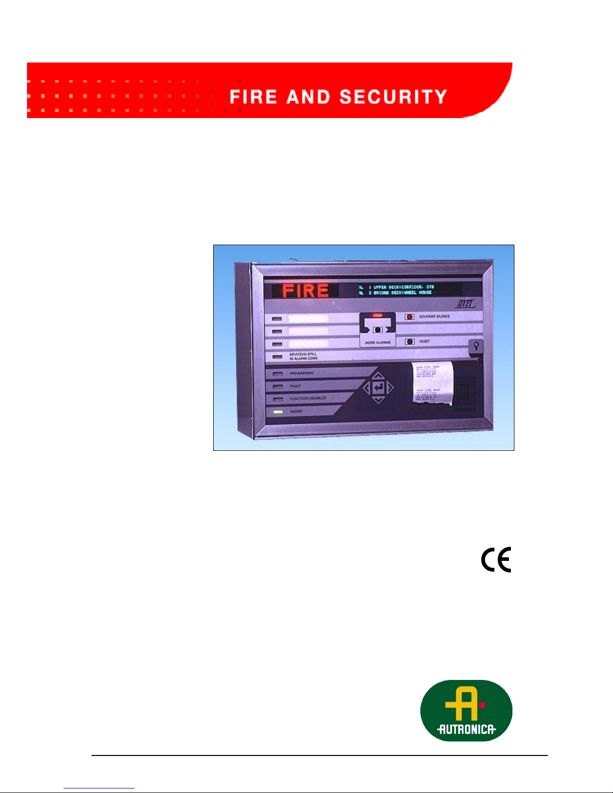
1. Operating /control panel
The operating panel consists of text display (information window),
indication lamps, operating buttons and a five elements key-pad.
See below. By means of these control and indication devices, the entire fire
alarm system is controlled
Fig. no. 1: BS-100 DYFI operating/control panel with indication lamps.
MORE ALARMS
This black control button
allows the second line of the
text display to be scrolled.
Revealing additional alarms
on the system.
SOUNDER SILENCE
When the red button is
pressed, all alarm devices
and the internal buzzer are
muted.
RESET
When the green button is
pressed, all events in the
system are reset.
PRINTER
Optional printer
MORE ALARMS
Red lamp lights when more
alarms are present.
Textdisplay
(Information window)
FIRE
Red lamp (sign) lights in
alarm condition.*
These lamps will have
custom designed text. (One
is red and the lower two are
amber (yellow). See app.A.
DEVICE(S) STILL IN
ALARM COND.
Amber (yellow) lamp lights
when an address (detector) is
automatically disabled.
PREWARNING
Amber (yellow) lamp lights
with pulsating light when a
prewarning situation has
occured.*
FAULT
Amber (yellow) lamp lights
for any fault.
Pulsating light. *
FUNCTION DISABLED
Amber (yellow) lamp lights
when any part of the system
is disabled (isolated).
MAINS
Green lamp lights when the
power is on.
Indication devices:
Operating buttons:
Five elements key-pad:
BS 100
DYFI
FIRE
MORE ALARMS
SOUNDER SILENCE
RESET
PREWARNING
FAULT
FUNCT. DISABL.
MAINS
A
utronica
NNNNNNNNNNNNNNNNNNNNNNNNNNNNNNN
NNNNNNNNNNNNNNNNNNNNNNNNNNNNNNN
DEVICE(S) STILL
IN ALARM COND.
The five elements key-pad
consists of four arrow keys and one
“carry-out” (enter) key.
The key-pad is used for information of
the system. The four arrow keys control
the cursor on the control panel text
display.
The keys for scrolling in the menu and
for moving the cursor up or down in the
menu text on the text display. These
arrow keys also scroll figures and letter
values when they are to be entered in
the menu functions.
Arrow keys for scrolling in the menu
and for moving the cursor to the left or
to the right in the menu on the text
display.
“Carry-out” (enter) key. Select the
menu part on which the cursor is
pointed.
* Lamps go steady when
“Sounder silence” button is
operated.

BS100 DYFI Operators handbook
P-BS100/FE - Rev.F / Doc/ 980114 6 Autronica Fire and Security AS
All address related text indicated in the display together with the text
printed out on the optional printer may be custom designed.
In this Operators handbook mainly default texts will be used.
2. Prewarning
2.1 Indications on the control panel in the event of a
“PREWARNING”
Example of text in the display (and on the optional printer):
PV 01 ADDRESS NO. 0504
INVESTIGATE PREWARNING LOCATION
Print out on optional printer:
If more than one prewarning events is registered, the display will change to:
PW 01 ADDRESS NO: 0504
02 PREWARNINGS REGISTERED
All active prewarnings may be seen through the menu function “SHOW
STATUS”, “PREWARNING”. Access to the menu is obtained by pressing
the ↵
↵↵
↵ key on the front panel.
2: The text display indicates
the address(es) of the
detector(s) in prewarning
condition.
1:The amber (yellow)
Prewarning - lamp lights
with pulsating lights.
3: The internal buzzer is
activated.
Functions activated at
“Prewarning”:
(BMFO) Common
prewarning output.
****PREWARNING****
DATE: 15.08.91 T1.04.57
PW 01 ADDRESS NO. 0504
Prewarning
Indications
BS 100
DYFI
FIRE
MORE ALARMS
SOUNDER SILENCE
RESET
PREWARNING
FAULT
FUNCT. DISABL.
MAINS
A
utronica
NNNNNNNNNNNNNNNNNNNNNNNNNNNNNNN
NNNNNNNNNNNNNNNNNNNNNNNNNNNNNNN
DEVICE(S) STILL
IN ALARM COND.
!

BS100 DYFI Operators handbook
P-BS100/FE - Rev.F / Doc/ 980114 7 Autronica Fire and Security AS
2.2 Actions to be taken in the event of a
“PREWARNING”:
A. Always treat a “PREWARNING” condition as if it is a fire alarm.
B. Follow all precautions described in the local fire instructions step by
step.
C. Open the control panel door.
D. Press the “SOUNDER SILENCE” button.
(The built in buzzer will give a short signal approx. every fourth minute
as long as the door remains open).
The “PREWARNING” indication lamp will now change to steady light.
E. Press the “RESET” button.
Wait for a while, while the following text appears in the display:
RESET PROCEDURE IN PROGRESS
WAIT ..............................
This text will remain for up to 60 seconds.
(The seconds are counted on the display with one point appearing every
sec. from 0 to 30 sec., and then removed the following 30 sec.)
The reset procedure is executed in this 60 seconds period.
If everything is in a normal condition the following text will appear in the
display:
RESET OK
NORMAL CONDITION
F. Close the door.
In normal condition only the “MAINS” indication lamp should be
illuminated when the door is closed.
Actions

BS100 DYFI Operators handbook
P-BS100/FE - Rev.F / Doc/ 980114 8 Autronica Fire and Security AS
3. Fire alarm
3.1 Indications on the control panel in the event of a
“FIRE” alarm:
Example of text in the display if detectors with address no. 345 has initiated
the alarm.:
AL 01 ADDRESS NO. 0345
Print out on the optional printer:
3: The text in the display indicates the
address of the detector which has initiated
the first alarm. Possible disablements
(isolations) of BMA, bells/sounders and
control outputs are indicated in the lower
line of the display.
1: The red FIRE indication
lamp lights with pulsating
light.
2: If the address initially had
given a prewarning, the
amber (yellow) Prewarning
lamp will light with steady
light.
4: The internal buzzer is
activated.
5: All sounders connected to
the fire alarm are activated.
(Control of sounder outputs
can be custom designed).
Functions activated at alarm condition:
(BMA) Alarm message to the fire-fighters.
(AUX) General control output.
(DHM) Control output for door holders.
Optional custom designed control outputs.
****FIRE****
DATE: 15.08.91 T1.05.02
AL 01 ADERESS NO.: 0345
Fire alarm
Indications
BS 100
DYFI
FIRE
MORE ALARMS
SOUNDER SILENCE
RESET
PREWARNING
FAULT
FUNCT. DISABL.
MAINS
A
utronica
NNNNNNNNNNNNNNNNNNNNNNNNNNNNNNN
NNNNNNNNNNNNNNNNNNNNNNNNNNNNNNN
DEVICE(S) STILL
IN ALARM COND.

BS100 DYFI Operators handbook
P-BS100/FE - Rev.F / Doc/ 980114 9 Autronica Fire and Security AS
3.2 Actions to be taken in the event of a “FIRE” alarm:
A: Follow all precautions described in the local fire instructions step
by step.
When the scene of the fire is investigated and the necessary actions
are carried out, the sounders may be switchedoff.
B: Open the control front door.
C: Press the”SOUNDER SILENCE” button.
All alarm devices (including the internal buzzer) will be muted.
The red “FIRE” indication lamp will switch to steady light.
All alarm outputs from the control panel will be turned of when the
“SOUNDER SILENCE” button is pressed.
However, the message to the Fire Fighters (BMA-) remains on.
If the silent alarm function (day/night) is in operation, the time delay (T1)
will start. Alarm outputs and the BMA-output will not be ativated.
If the alarm is acknowledged within the delay period (T1) by operating the
“SOUNDER SILENCE”-button, an additional delay period (T2) will be
activated.
If the “SOUNDER SILENCE”-button not is operated within the delay
period T1 or reset within the delay period T2, the alarm outputs and BMA
will be activated.
The alarm delay of sounder outputs and the BMA-output applies only for
alarm from detectors. Alarms from manual call points or 2 or more
detectors, over-ride the alarm delays T1 + T2, and the sounder outputs and
the BMA-output will operate immediately.
Silent alarm/alarm organisations (list L3.11) is controlled by external
manual switch with time controlled relay or automatic from external clock.
If the “MORE ALARMS” indication lamp lights, please see section 4.1
D: Press “RESET”-button.
The following text will appear in the text display:
RESET PROCEDURE IN PROGRESS
WAIT..........................
Actions
!

BS100 DYFI Operators handbook
P-BS100/FE - Rev.F / Doc/ 980114 10 Autronica Fire and Security AS
This text will remain in the display for up to 60 seconds.
The reset procedure is as the one described in section 2.2. part E.
If everything is normal after the reset procedure is carried out, the following
text will appear in the display:
RESET OK
NORMAL CONDITION
This text remains in the display for 15 seconds, and then the menu selection
will appear.
After resetting, an address may still be in an alarm condition. This can be
due to mechanical demage, water damage, the presence of smoke still within
the chamber or an electrical fault. The address still in the alarm condition,
will automatically be disabled (isolated from the rest of the system).
The amber (yellow) “DEVICE(S) STILL IN ALARM COND.” - indication
lamp will light, and the following text will appear in the display:
01 ALARM ADDRESS(ES) DISABLED
CONTROL PANEL IN ABNORMAL CONDITION
Contact technical personnel.
E: Close the door.
In normal condition only the “MAINS” indication lamp shall remain
illuminated when the door is closed.
While an address is automatically disabled, the amber (yellow) “DEVICES
STILL IN ALARM COND.” indication lamp also will be lit.
If the alarm condition disappears, the indication lamp will turn off and the
address automatically restored to the system.
See also
special
functions
according to
SOLAS-
requirements,
described in
appendix A.

BS100 DYFI Operators handbook
P-BS100/FE - Rev.F / Doc/ 980114 11 Autronica Fire and Security AS
4. More alarms
4.1 Indications on the control panel in the event of
“MORE ALARMS”:
Example of text in the display if more then two detector addresses (here we
show 3) are in alarm condition:
AL 01 ADDRESS NO: 0007
AL 03 ADDRESS NO: 0002
Print-out on the optional printer:
1: The red FIRE indication
lamp lights with pulsating
light.
2: The amber (yellow)
PREWARNING lamp lights
with pulsating light.
However, if the address
initially had given a
prewarning, the lamp will
light with steady light.
5: The internal buzzer is
activated.
6: All sounders connected to
the fire alarm are activated.
(Control of sounder outputs
can be custom designed.)
Functions activated at alarm condition:
(BMA) Alarm message to the fire-fighters.
(AUX) General control output.
(DHM) Control output for door holders.
Optinal custom designed control output.
****FIRE****
DATE: 21.10.91 T1.15.33
A
L 03 ADDRESS NO.: 0002
**** FIRE ****
DATE: 21.10.91 T1.15.28
A
L 02 ADDRESS NO: 0003
**** FIRE ****
DATE: 21.10.91 T1.15.24
A
L ADDRESS NO: 0007
3: The red MORE
ALARMS indication
lamp lights.
4:The upper line in the
display indicates the first
address in alarm condition.
The lower indicates the last
address in alarm condition.
More alarms
Indications
BS 100
DYFI
FIRE
MORE ALARMS
SOUNDER SILENCE
RESET
PREWARNING
FAULT
FUNCT. DISABL.
MAINS
A
utronica
NNNNNNNNNNNNNNNNNNNNNNNNNNNNNNN
NNNNNNNNNNNNNNNNNNNNNNNNNNNNNNN
DEVICE(S) STILL
IN ALARM COND.

BS100 DYFI Operators handbook
P-BS100/FE - Rev.F / Doc/ 980114 12 Autronica Fire and Security AS
4.2 Actions to be taken in the event of “MORE
ALARMS”:
A: Follow all precautions described in the local fire instructions step
by step.
B: Open the control panel front door.
C: Press the "MORE ALARMS"-button.
At the first time press on the button, the second alarm will normally be
indicated on the lower line.
However, if the following functions - BMA, bells/sounders and control
outputs are disabled (isolated) this will be indicated on the lower line for a
short period before the second alarm is indicated.
Pressing the button a second time will show the 3rd alarm in the display.
Each new press of the button will show the next alarm in the queue.
If the button is pressed for 15 seconds, the last alarm will automatically
show on the lower line.
D: Press “SOUNDER SILENCE”-button.
All alarm devices including the internal buzzer will be turned off.
See section 3.2 C for description of silent alarm function (day/night).
The ref “FIRE” indication lamp will switch to steady light.
All alarm outputs from the control panel will be turned off when the
“SOUNDER SILENCE” button is pressed.
However, the message to the Fire Fighters (BMA-) is not turned off.
E: Press “RESET”-button.
The following text will appear in the text display:
RESET PROCEDURE IN PROGRESS
WAIT.............................
This text will remain in the display for up to 60 seconds. The reset
procedure is identical to the one described in section 2.2.
Actions
Special
SOLAS-
functions are
described in
appendix A.

BS100 DYFI Operators handbook
P-BS100/FE - Rev.F / Doc/ 980114 13 Autronica Fire and Security AS
If everything is in a normal condition the following text will appear in the
display:
RESET OK
NORMAL CONDITION
This text remains in the display for 15 seconds, and then the menu selection
will appear.
After resetting, one or more addresses may still be in an alarm condition.
This can be due to mecanical damage, water damage, the presence of smoke
still within the chamber or an electrical fault. The addresses still in the alarm
condition, will automatically be disabled (isolated from the rest of the
system).
The following text will appear in the display:
01 ALARM ADDRESS(ES) DISABLED
CONTROL PANEL IN ABNORMAL CONDITION
Contact technical personnel.
F: Close the door.
In normal condition only the “MAINS” indication lamp shall remain
illuminated when the door is closed.
While an address is automatically disabled, the amber (yellow) “DEVICES
STILL IN ALARM COND.” indication lamp also will be lit.
If the alarm condition disappears, the indicator lamp will turn off and the
address automatically restored to the system.

BS100 DYFI Operators handbook
P-BS100/FE - Rev.F / Doc/ 980114 14 Autronica Fire and Security AS
5. Fault
5.1 Indications on the control panel in the event of
“FAULT”:
5.1.1 Indications at more (multiple) fault
If more (multiple) faults (here we show two) the following indications can
be shown in the display:
FA 01 ADERESS NO: 0123
LOOP/DET.FAULT: 1 SYSTEM FAULT: 1
Print out on optional printer:
This text means that there is one fault present on detector no. 0123, and that
there is one system fault present (sounder circuit). The nature of the fault
can be identified by using the menu.
Access to the menu is obtained by pressing the
↵↵↵↵-button on the five
elements key-pad.
1: The amber (yellow)
FAULT lamp lights with
pulsating light.
3: The internal buzzer is
activated.
Functions activated at “Fault”:
BMF - Common fault warning output.
****SYSTEM FAULT****
DATE: 25.11.91 T1.09.52
SF 1 SOUNDER CIRCUIT 4 OPEN
****DETEKTOR FAULT****
DATE: 25.11.91 T1.09.50
FA 1 ADDRESS NO: 0123
(EO) NO OR SHORT ANSWER-PULSE
2: The text display indicates the nature of
the fault. If the following letters are
indicated at the start of the upper line:
FA means loop / detector fault.
SF means system fault.
Fault
Indications
More faults
BS 100
DYFI
FIRE
MORE ALARMS
SOUNDER SILENCE
RESET
PREWARNING
FAULT
FUNCT. DISABL.
MAINS
A
utronica
NNNNNNNNNNNNNNNNNNNNNNNNNNNNNNN
NNNNNNNNNNNNNNNNNNNNNNNNNNNNNNN
DEVICE(S) STILL
IN ALARM COND.

BS100 DYFI Operators handbook
P-BS100/FE - Rev.F / Doc/ 980114 15 Autronica Fire and Security AS
5.2 Actions to be taken at “FAULT”:
A. Press the “SOUNDER SILENCE”-button.
The internal buzzer is muted, and the amber (yellow) “FAULT”
indication lamp will switch to steady light.
B: Note the fault text indicated in the display and file the printout
from the optional printer.
C: Contact technical /serice personnel.
Actions

BS100 DYFI Operators handbook
P-BS100/FE - Rev.F / Doc/ 980114 16 Autronica Fire and Security AS
6. Menu
6.1 Menu structure
The whole menu structure is shown here, but “SYSTEM
CONFIGURATION” and “SERVICE” is described in full detail within the
“Commissioning handbook” - BS-100.
Select Main menu (Program P1-BS100-3-20 / P5-BS100-3E20)
Out/in- Disable Address
control Zone
1) Controls BT-outputs (AUX,DHM)
3) Sounders Controls (1-240)
Fire-brigade (BMA,BMFO,BMF)
Restore Address
Zone
Controls BT-outputs (AUX,DHM)
Klokker Controls (1-240)
Fire-brigade (BMA,BMFO,BMF)
Show-status Alarm
Prewarning
Addr./loop-fault
System fault
Disablements
Alarm counter
Stored events (last 150)
Test Front panel (lamp test)
BMA,BMFO, BMF
Fault
Sounders
Buzzer
System Sensitivity Address Single address
Beyond limit Loop
Total Printer
Polluted Printer Display
Display
Internal Program-version
Adjust-clock
Show-clock
2) Configuration Comm.channel Panel address
Alarm info
Silencealarm T1
(Alarm delay) T2
BU-units (display units)
DYFI-changes Alarm
Battery-voltage Prewarning
Pocket pager Filter
cont. on next page: System-Data
Menu
Menu structure

BS100 DYFI Operators handbook
P-BS100/FE - Rev.F / Doc/ 980114 17 Autronica Fire and Security AS
1,2) Data Change 1) Changing of display
and printer texts.
2) Changing of output
controls, alarm outputs
and disabling outputs.
Add
Print out Detector data
Printer texts
Feed paper
Service Report DYFI-factors Single address
Restart Main prc. (processor)
Loops (processor)
Clear
Disable Loop
Internal buzzer
Internal printer
Restore Loop
Internal buzzer
Internal printer
Test Address-in-alarm
Styringer Styringer
BT-utganger
Adress- Loop From detector
control From front
Data control Transfer comm.port Yes
No
Select “RET” to go 1 step back in the menu structure.
Select “MM” to return to main menu.
1. Password protected on level 1. (Operator level).
2. Password protected on level 2. (Service level).
3. Can be password protected in different market and installations.
6.2 Password protected functions
Some of the functions in the BS-100 menu are password protected on two
levels.
Following functions are password protected:
Password level 1): "OPERATOR LEVEL".
* Disable - Controls
* System - Data
* Disable - Sounders
* Changing of display and printer texts
Password level 2): "SERVICE LEVEL"
* System - Configuration
* Service
* Changing of output controls, alarm outputs and
disabling groups.
Password
Menu cont...

BS100 DYFI Operators handbook
P-BS100/FE - Rev.F / Doc/ 980114 18 Autronica Fire and Security AS
6.3 Menu operation
Information given in this section follows the MENU STRUCTURE given in
section 6.1.
That particular parts of the menu structure is shown prior to each section in
order to ease the function overwiew.
When the control panel front door is opened, the following text will appear
in the display:
AUTRONICA FIRE ALARM SYSTEM BS-100
USER MENU
Then the text changes to:
SELECT MAIN MENU PRESS ↵
↵↵
↵
USERS INSTRUCTION PRESS ßßßß
If the operator selects to read the short form users instruction by pressing the
ß arrow key in the key-pad, the following text will appear in the display:
USER INSTRUCTION. PANEL IS OPERATED BY
USING MENU FUNCTIONS. TO CONT. PRESS ßßßß
VARIOUS MENU FUNCTIONS ARE SELECTED BY
USE OF ßÝ
ßÝßÝ
ßÝ AND ßÝ
ßÝßÝ
ßÝ LAST PICT. NEXT PICT. ßÝ
ßÝßÝ
ßÝ
CHOSEN FUNCTION IN MENU IS MARKED AND
IS EXECUTED BY PRESSING ↵↵↵↵ ßßßß ÝÝÝÝ
IN ADDITION TO MENU FUNCTIONS THERE ARE
TWO FUNCTIONS WHICH CAN BE USED ßßßß ÝÝÝÝ
“RET” WHEN THIS FUNCTION IS CHOSEN,
YOU TAKE ONE STEP BACK IN MENU ßßßß ÝÝÝÝ
WHEN SELECTING “MM” THAT TAKES
YOU BACK TO MAIN MENU ßßßß ÝÝÝÝ
Operation
Short form
operators
instruction.
This appears on
the display on
the front panel

BS100 DYFI Operators handbook
P-BS100/FE - Rev.F / Doc/ 980114 19 Autronica Fire and Security AS
“ARROWS” ARE USED IN ORDER TO BRING UP
MORE SUB-MENUES WITHIN SAME MENU LEVEL ßÝ
ßÝßÝ
ßÝ
ßßßß ÝÝÝÝ ALSO TO BE USED WHEN SETTING REQUIR.
VALUES OF DIFFERENT PARAMETERS ßßßß ÝÝÝÝ
ßÝ
ßÝßÝ
ßÝ SCROLLING FIGURES / VALUES /CHARACTERS
WHEN TO BE SET ßßßß ÝÝÝÝ
USERS INSTRUCTION FINISHED
TO MAIN MENU: PRESS ↵
↵↵
↵
6.4 "Main menu"
If the “ MAIN MENU” is selected, part of main menu will appear in the
display:
MAIN MENU: SELECT WITH ⇐
⇐ ⇐
⇐ ÞÞÞÞ PRESS ↵
↵↵↵
OUT/IN-CONTROL SHOW-STATUS TEST
ßßßß
The arrow pointing down next to the word TEST indicates more text in the
line. By pressing the ß arrow key in the key-pad, the remaining text is
shown in the lower line:
MAIN MENU: SELECT WITH ⇐
⇐ ⇐
⇐ ÞÞÞÞ PRESS ↵
↵↵
↵
SYSTEM FEED-PAPER SERVICE RET ÝÝÝÝ
The required function is selected by moving the cursor by means of the
arrow keys in the key-pad on the control panel front.
The function is selected, by pressing the
↵↵↵↵-key.
Out/in-control
Show-status
Test
System
Feed paper
Service
Main menu

BS100 DYFI Operators handbook
P-BS100/FE - Rev.F / Doc/ 980114 20 Autronica Fire and Security AS
7. Out/in-control
Main menu
Out/in-control Disable Address
Zone
1) Controls* BT-outputs(AUX,DHM)
3) Sounders* Controls (1-240)
Fire-brigade (Fire fighters)
Restore Address
Zone
Controls BT-outputs
Sounders Controls
Fire-brigade (Fire fighters)
If the “OUT/IN-CONTROL” is selected in the main menu, the following
text will appear in the display:
OUT/IN-CONTROL: SELECT WITH ⇐
⇐ ⇐
⇐ ÞÞÞÞ
PRESS ↵
↵↵
↵
DISABLE RESTORE MM
7.1 Disable
When disabling parts of the system, the amber (yellow) lamp “FUNCTION
DISABLED” on the front of the control panel will light as long as the
disabling lasts.
All disablements must be allocated a time period.
By selecting manually disable time of 99 hours, the function will be disabled
until restored. The maximum automatic disable time is 24 hours. When
disable time isout, those disabled functions will automatically be restored.
If “OUT/IN-CONTROL” is selected and then “DISABLE”, the following
text will appear in the display:
DISABLE: SELECT WITH ⇐
⇐ ⇐
⇐ ÞÞÞÞ PRESS ↵↵↵↵
ADDRESS ZONE CONTROLS SOUNDERS ßßßß
("FIRE BRIGADE" will appear when ß is pressed.)
Out/in-control
Disable

BS100 DYFI Operators handbook
P-BS100/FE - Rev.F / Doc/ 980114 21 Autronica Fire and Security AS
7.1.1 Disable address
When disabling an address (detector, manual call point or an interface unit),
the address will be isolated and not generate an alarm, prewarning or fault as
long as the disabling lasts.
If “OUT/IN-CONTROL”, “DISABLE” and then “ADDRESS” are selected,
the following text will appear in the display:
DISABLE ADDRESS(ES)
SELECT ADDRESS 0000 RET MM
Select the address no. to be disabled and press ↵
↵↵
↵.
The following text will appear in the display:
1 ADDRESS(ES) ENTERED FOR DISABLEMENT
ADDRESS XXXX TIME RET MM
The selected address is ready to be disabled.
This address is not yet disabled, - only prepared for disablement!
The next address (XXXX) will automatically appear. Select this or another
addres by pressing ↵
↵↵
↵ .
If selected address is not present in the system, the following text will
appear in the display:
THE ADDRESS DOES NOT EXIST IN PANEL
LEGAL ADDRESSES xxxx TO XXXX
xxxx - lowest address in the system.
XXXX - highest address in the system.
When all addresses to be disabled are selected, move the cursor to “TIME”
by means of the arrow key and press
↵↵↵↵.
The following text will appear in the display:
DISABLEMENT OF n ADDRESS(ES)
DURATION 02 HOURS RET MM
n = number of addresses ready for disablement.
The time limit is automatically set to 2 hours (default value).
Press ß Ý to select other values and press ↵
↵↵
↵ .
Disable address

BS100 DYFI Operators handbook
P-BS100/FE - Rev.F / Doc/ 980114 22 Autronica Fire and Security AS
The following text will appear in the display:
DISABLEMENT OF ADDRESS(ES) OK
NUMBER: n TOTAL m RET MM
n = number of addresses disabled in this operation.
m = number of addresses disabled total in the system.
7.1.2 Disable zone
It is only possible to disable zones if zones have been programmed in
custom data. If not programmed the menu will not allow you to enter zone
area.
When disabling zone(s) the addresses in the zone will be isolated and will
not generate an alarm, prewarning or fault.
The total number of zones are 240. Zone addresses are 1-240.
If “OUT/IN-CONTROL”, “DISABLE” and then “ZONE” are selected, the
following text will appear in the display:
DISABLE ZONE 001 NEXT PREVIOUS TIME
‘ZONE TEXT’ RET MM
Select the zone number for disablement by pressing the Ý ß -key.
It is also possible to move the cursor to “NEXT” and “PREVIOUS” and press
↵↵↵↵ to select the zone numbers.
When correct zone number 1-240 is selected, move the cursor to “TIME”,
press
↵↵↵↵, and the following text will appear in the display:
DISABLE ZONE 001 NEXT PREVIOUS TIME
TIME - DURATION 02 HOURS RET MM
Select duration for disablement and press ↵
↵↵
↵.
The following text will appear in the display:
ZONE YYY DISABLE
MORE ? YES NO
YYY is selected and that sone is disabled.
If more than one zone is to be disabled select “YES”, press ↵
↵↵
↵ and repeat the
disable procedure.
Select “NO” to end the “DISABLE ZONE” procedure.
Disable zone

BS100 DYFI Operators handbook
P-BS100/FE - Rev.F / Doc/ 980114 23 Autronica Fire and Security AS
7.1.3 Disable controls (password protected on operator level).
Disabling controls, ensures that output controls will not activate in the event
of a alarm:
DISABLE OUTPUT CONTROLS
BT-OUTPUTS CONTROLS RET MM
7.1.3.1 Disable BT-outputs (DHM, AUX)
If the BT-outputs are disabled, the outputs DHM (door holder magnets) and
AUX (control-/alarm output) will not operate at alarm.
If “OUT/IN-CONTROL”, “DISABLE”, “CONTROLS” are selected and
then the “BT-OUTPUTS”, the following text will appear in the display:
DISABLEMENT OF BT-OUTPUTS
DUREATION 02 HOURS RET MM
Select theduration time fordisablement by means of the arrow keys and press
↵↵↵↵.
The following text will appear in the display:
DISABLEMENT OF BT-OUTPUTS
DISABLEMENT EXECUTED
Press ↵
↵↵
↵ and the system will return to “DISABLE CONTROLS”-menu with
possibility to return to the main menu.
Disable controls

BS100 DYFI Operators handbook
P-BS100/FE - Rev.F / Doc/ 980114 24 Autronica Fire and Security AS
7.1.3.2 Disable controls (BSJ-100/101)
When disabling the controls, the control-outputs from external controloutput modules BSJ-100/BSJ-101 will not operate at alarm.
If “OUT/IN-CONTROL”, “DISABLE”, “CONTROLS” are selected and
then the “CONTROLS”, the following text will appear in the display:
DISABLEMENT OF CONTROLS
DURATION 02 HOURS RET MM
Select duration time for disablement by means of the arrow key and press ↵
↵↵
↵.
The following text will appear in the display:
DISABLEMENT OF CONTROLS
DISABLEMENT EXECUTED
Press
↵↵↵↵, and the system will return to “DISABLE CONTROLS”, with
possibility to return to the main menu.
Output controls can be disabled/restored from a superior computer
through the communication line..
7.1.4 Disable sounders (AK) (can be password protected in different
countries
- see Appendix A).
When disabling sounder output(s), the sounder(s) will not be activated at
alarm. This is applicable for the 4 standard sounder outputs and the outputs
from external sounder output board (BSB-100).
If “OUT/IN-CONTROL”, “DISABLE” and then “SOUDERS” are selected,
the following text will appear in the display:
DISABLEMENT OF SOUNDERS
DURATION 02 HOURS RET MM
Select the duration time for disablement by means of the arrow key and
press ↵
↵↵
↵.
The following text will appear in the display:
DISABLE SOUNDERS
DISABLEMENT EXECUTED
Press ↵
↵↵
↵, an the system will return to the “DISABLE”-menu with possibility
to return to the main menu.
Disable
sounders

BS100 DYFI Operators handbook
P-BS100/FE - Rev.F / Doc/ 980114 25 Autronica Fire and Security AS
7.1.5 Disable Fire Brigade (BMA, BMFO, BMF)
When disabling the Fire Brigade output (BMA), prewarning (BMFO) and
fault output (BMF) will also be disabled
If “OUT/IN-CONTROL”, “DISABLE” and then “FIRE BRIGADE” are
selected, the following text will appear in the display:
DISABLEMENT OF FIRE BRIGADE OUTPUT
DURATION 02 HOURS RET MM
Select duration time by means of the arrow key and press ↵
↵↵
↵.
The following text will appear in the display:
DISABLEMENT OF FIRE BRIGADE OUTPUT
DISABLEMENT EXECUTED
Press ↵
↵↵
↵, and the system will return to the “DISABLE”-menu with
possibility to return to the main menu.
7.2 Restore
When disable parts of the system (functions) are restored, these will revert
to their normal function.
The “FUNCTION DISABLED” lamp will turn off only when all
disablements have been retsored.
If “OUT/IN-CONTROL” and then “RESTORE” are selected, the following
text will appear in the display:
RESTORE: SELECT WITH ⇐
⇐ ⇐
⇐ ÞÞÞÞ
PRESS ↵
↵↵
↵
ADDRESS ZONE CONTROLS SOUNDERS ßßßß
("RESTORE", "FIRE BRIGADE" will appear when ß is pressed.)
7.2.1 Restore address
Before restoring addresses it is always advisable to check the sensitivity to
ensure that an alarm is not present.
By restoring the address(es), the addresses will revert to their normal
function.
Disable
Fire Brigade
Restore
Restore
address

BS100 DYFI Operators handbook
P-BS100/FE - Rev.F / Doc/ 980114 26 Autronica Fire and Security AS
If "OUT/IN-CONTROL", "RESTORE" and then "ADDRESS” are selected,
the following text will appear in the display:
RESTORE ADDRESS(ES)
ADDRESS 0000 RET MM
Select the address(es) to be restored by means of the arrow key and press ↵.
↵.↵.
↵.
The following text will appear in the display:
n ADDRESS(ES) RESTORED OK
ADDRESS XXXX RET MM
n = number of restored address(es).
The next address (XXXX) will automatically appear. Select that or another
address by means of the arrow key and press ↵
↵↵
↵.
If selected address is not present in the system, the following text will
appear in the display:
THE ADDRESS DOES NOT EXIST IN PANEL
LEGAL ADDRESSES xxxx TO XXXX
xxxx - the lowest address in the system.
XXXX - the highest address in the system.
7.2.2 Restore zone
It is possible to restore only if zones are programmed in custom data.
When restoring zones, addresses connected to the zones will revert to their
normal function.
If “OUT/IN-CONTROL”, “RESTORE” and then “ZONE” are selected, the
following text will appear in the display:
RESTORE OF ZONE 001 NEXT PREVIOUS OK
‘zonetext zone 1’ RET MM
Select zone number to be restored by means of the arrow keys and press
ß Ý.
It is also possible to move he cursor to “NEXT” and “PREVIOUS” and
press ↵
↵↵
↵ to select zone number.
Restore zone

BS100 DYFI Operators handbook
P-BS100/FE - Rev.F / Doc/ 980114 27 Autronica Fire and Security AS
When correct zone number is selected, move the cursor to “OK” , press ↵
↵↵
↵
and the following text will appear in the display:
ZONE YYY RESTORED
MORE ? YES NO
YYY is selected and restored zone.
If more than one zone is to be restored, select "YES", press ↵
↵↵
↵ and repeat the
restoring procedure.
Select "NO" to end the "RESTORE ZONE"-menu.
7.2.3 Restore controls
By restoring the controls, these will activate at alarm.
If "OUT/IN-CONTROL", "RESTORE" and then "CONTROLS" are
selected, the following text will appear in the display:
RESTORE OUTPUT CONTROLS
BT-OUTPUTS CONTROLS RET MM
7.2.3.1 Restore BT-outputs (DHM, AUX)
By restoring BT-outputs, the outputs DHM (door holder magnets) and AUX
(control-/alarm output) will activate at alarm.
If "OUT/IN-CONTROL", "RESTORE", "CONTROLS" and then "BTOUTPUTS" are selected, the following text will appear in the display:
RESTORE OUTPUT CONTROLS
RESTORE COMPLETED
Press ↵
↵↵
↵, and the system will return to the "RESTORE CONTROLS" with
possibility to return to the main menu.
Restore controls

BS100 DYFI Operators handbook
P-BS100/FE - Rev.F / Doc/ 980114 28 Autronica Fire and Security AS
7.2.3.2 Restore controls (BSJ-100/101)
By restoring the controls, the control outputs from external control output
module(s) BSJ-100/BSJ-101 will activate at alarm.
If "OUT/IN-CONTROL", "RESTORE", "CONTROLS" and then
“CONTROLS" are selected, the following text will appear in the display:
RESTORE OUTPUT CONTROLS
RESTORE COMPLETED
Press ↵
↵↵
↵, and the system will return to the "RESTORE CONTROLS"-menu
with possibility to return to the main menu.
7.2.4 Restore sounders (AK)
By restoring the sounder(s), the sounder(s) will revert to their normal
function at fire alarm. This is applicable for the 4 standard sounder outputs
and the outputs from external sounder output board (BSB-100).
If "OUT/IN-CONTROL", "RESTORE", and then "SOUNDERS" are
selected, the following text will appear in the display:
RESTORE: SELECT WITH ⇐
⇐ ⇐
⇐ ÞÞÞÞ PRESS ↵
↵↵
↵
RESTORE COMPLETED
Press
↵↵↵↵, and the system will return to the "RESTORE"-menu with
possibility to return to the main menu.
7.2.5 Restore Fire Brigade/Fighters (BMA, BMFO, BMF)
By restoring the Fire Brigade/Fighters output BMA (Alarm output), BMFO
(Prewarning output) and BMF (Fault output), the output will revert to their
normal function at alarm, prewarning or fault.
If "OUT/IN-CONTROL", "RESTORE" and then "FIRE BRIGADE" are
selected, the following text will appear in the display:
RESTORE: SELECT WITH ⇐
⇐ ⇐
⇐ ÞÞÞÞ PRESS ↵
↵↵
↵
RESTORE COMPLETED
Press ↵
↵↵
↵, and the system will return to the "RESTORE"-menu with
possibility to return to the main menu.
Restore
sounders
Restore
Fire Brigade

BS100 DYFI Operators handbook
P-BS100/FE - Rev.F / Doc/ 980114 29 Autronica Fire and Security AS
8. Show status
Main menu
Show status Alarm
Prewarning
Addr./loop-fault
System fault
Disablements
Alarmcounter
Stored events (last 150)
When "SHOW STATUS” is selected, the following text will appear in the
display:
SHOW STATUS SELECT WITH ⇐
⇐ ⇐
⇐ ÞÞÞÞ PRESS ↵
↵↵
↵
ALARM PREWARNING ADDR./LOOP-FAULT ßßßß
By pressing the ß key the rest of the text will appear in the lower line.
Alarm: The last 20 stored alarms
*)Prewarning: The last 20 active prewarnings.
*)Addr./loop-fault: The last 20 active faults from detectors/detector-
loops.
*)System fault: The last 20 active system faults.
Disablements: All stored disablements.
Alarmcounter: Number of stored alarms.
Stored-events: The last 150 stored events.
*) = These events are cleared when the "RESET"-button is pressed.
Move the cursor to the required function and press the ↵
↵↵
↵ key.
For the function "SHOW STATUS", option "ALARM", the text in the
display will be:
SHOW STATUS ALARM
ADDRESS 0296 DATE: 11.02.91 TI. 16.25
Use the ß Ý arrow keys to scroll through the stored alarms.
Use the ↵
↵↵
↵ arrow keys to return to "SHOW STATUS” menu.
"STORED EVENTS" is continually up-dated detailing the last 150 events in
the system. The last event will always be shown first.
Feed-paper
Service*
Out/in-control
Show status
Test
System
Main Menu
Show status
Stored events

BS100 DYFI Operators handbook
P-BS100/FE - Rev.F / Doc/ 980114 30 Autronica Fire and Security AS
All activities eg. alarms, prewarnings, faults, silence, reset, open and closing
front door etc. are stored with date and time.
If the "STORED EVENTS" function is selected, the display will indicate as
follows:
SHOW STORED EVENTS
ON : PRINTER DISPLAY RET MM
As indicated in the above, the stored information can be shown in the
display or on the optional printer. The printer will start with the latest
events.
The optional printer may be stopped at any time simply by pressing one of
the arrow keys in the key-pad located on the control panel front.
If display is selected, use the ß Ý arrow keys to scroll through "STORED
EVENTS".
The "STORED EVENTS" function presents the events in a reduced format
with date and time.
The content is:
* All alarms.
* All prewarnings.
* All faults (internal and external).
* All button operations at event handling (SILENCE/RESET).
* All automatic disablements at reset.
* All disablements carried out by means of the menu and the arrow
keys.
* All disablements executed via data line.
* All manually executed restorations.
* All group disablements, externally controlled.
* All group restorations, externally controlled.
* All functions related to alarm organisation (time delay of external
alarm).
* All functions entered (carried out) via password.
* Openings of the control panel front door.
* Closing of the control panel front door.
* "Cold-start", the system has been powered up.
* "Warm-start", ("watch-dog" internal function).

BS100 DYFI Operators handbook
P-BS100/FE - Rev.F / Doc/ 980114 31 Autronica Fire and Security AS
9. Test
Main menu
Test Front panel
BMA/BMF/BMFO
Fault
Sounders
Buzzer
When entering the "TEST"-function in the main menu, the following text
will appear in the display:
TEST
FRONT PANEL BMA/BMF/BMFO FAULT ßßßß
In the lower line the ß arrow indicates more text.
Move the cursor to the required function and press the ↵
↵↵
↵ key.
9.1 Front panel
If the "FRONT PANEL" function is selected, the display is tested by
showing all characters, and all lamps on the control panel front will light.
The function is stopped by pressing any of the arrow keys. A special test
sequence is also printed out on the optional printer, if this is installed.
Repeater units may also be tested in this function by opening door
(BU-100/101) or operating test button (BU-70).
9.2 BMA/BMF/BMFO
If the "BMA/BMF/BMFO" function is selected the following text will
appear in the display:
TEST OF TRANSMISS. LINE TO FIRE BRIGADE
WHEN COMPLETED PRESS ↵
↵↵
↵
This function will activate the corresponding outputs.
Inform the fire brigade if connected!
Test
Front panel
BMA/BMF/BMFO
!

BS100 DYFI Operators handbook
P-BS100/FE - Rev.F / Doc/ 980114 32 Autronica Fire and Security AS
9.3 Fault
If the "FAULT" function is selected the following text will appear in the
display:
TEST EARTH-FAULT ACTIVE
. . . . .
The test process takes one minute. It is indicated by dots appearing in the
display for the first half minute. Then the sequence is reversed the next half
minute. This test process is a real one, and an genuine earth fault is
introduced. The internal buzzer is activated. The test is terminated by
pressing the ↵
↵↵
↵ button.
Normal test function gives earth fault on the central panel.
When this earth fault test sequence is finished, the next sequence will
automatically start. The following text will appear in the display:
TEST ADDRESS FAULT ACTIVE
. . . .
In this sequence the control panels ability to receive fault messages from the
detectors/detector-loops is tested. This sequence also lasts for one minute.
A fault message on address 0001 will be shown provided this address is not
disabled. The fault will activate the internal buzzer.
When this address test sequence is finished, the next sequence will
automatically start. The following text will appear in the display:
TEST BATTERY ACTIVE
. . . .
This sequence (which is a real battery capacity test) lasts for 10 seconds and
normally should not give any fault message. (This test is automatically
carried out by the BS-100 every day at 10:00 AM).
Before continuing operate the "SOUNDER SILENCE" and "RESET"
pushbuttons.
Fault

BS100 DYFI Operators handbook
P-BS100/FE - Rev.F / Doc/ 980114 33 Autronica Fire and Security AS
9.4 Sounders
When the previous test sequence is completed, return to the "TEST" option
and select the "SOUNDERS” sequence by moving the cursor with the arrow
keys and then press the ↵
↵↵
↵ key.
The following text will appear in the display:
SOUNDER TEST ACTIVE
WHEN COMPLETED PRESS ↵
↵↵
↵
During this test sequence all alarm outputs will be activated (0,5 second ON
every 8th second). The sequence is terminated by pressing the ↵
↵↵
↵ key.
9.5 Buzzer
When the sounder test sequence is finished, return to the "TEST" option and
select the "BUZZER" sequence by moving the cursor with the arrow keys
and then press the ↵
↵↵
↵ key.
The following text will appear in the display:
BUZZER TEST ACTIVE
WHEN COMPLETED PRESS ↵
↵↵
↵
The built-in buzzer will be activated until the buzzer test sequence is
terminated by pressing the ↵
↵↵
↵ key.
Buzzers on all repeater units will also operate during this test sequence.
Sounders
Buzzer

BS100 DYFI Operators handbook
P-BS100/FE - Rev.F / Doc/ 980114 34 Autronica Fire and Security AS
10. System
Main menu
System Sensitivity Address Single address
Beyond-limit Loop
Polluted Total Printer
Display
Internal Program-version
Adjust-clock
Show-clock
Configuration
*
Comm.channel
Silence alarm (alarm delay) Standard (T1)
BU-units Additional (T2)
DYFI-changes Alarm
Battery voltage Prewarning
Pocket Pager Filter
1,2) Data* Change 1)Changing of display
and printer texts.
2)Changing of output
controls, alarm
outputs and
disabling groups.
Add
Print-out Detector data
Transfer Printer texts
* See section 6.1 - "Menu structure".
Select "SYSTEM" in the main menu, and the following text will appear in
the display:
SYSTEM SELECT WITH ⇐
⇐ ⇐
⇐ ÞÞÞÞ PRESS ↵
↵↵
↵
SENSITIVITY INTERNAL CONFIG. DATA MM
The rest of the text will appear by pressing the ß key.
System

BS100 DYFI Operators handbook
P-BS100/FE - Rev.F / Doc/ 980114 35 Autronica Fire and Security AS
10.1 Sensitivity
The "SENSITIVITY" function enables the user to read the analogue value of
an individual detector(address), from a loop or from all addresses connected
to the control panel. The analogue value is automatically updated every 5th
second. To achieve all advantages available in this function, the optional
printer must be fitted to the control panel.
An analogue value may be seen even when the device is disabled.
If the "SENSITIVITY" function is selected by moving the cursor with the
arrow- and enter-keys, the following text will appear in the display:
SENSITIVITY
ADDRESS BEYOND-LIMIT POLLUTED RET MM
10.1.1 Address
By selecting "ADDRESS" the following text will appear in the display:
ADDRESS SENSITIVITY
SINGLE ADDRESS LOOP TOTAL RET MM
If "SINGLE-ADDRESS" is selected, the following text will appear in the
display:
ADDRESS SENSITIVITY
ADDRESS: 0000 RET MM
Here it is necessary to select the address number by moving the cursor to the
correct column and then set the number in question by using the ß or Ý
keys. When the correct address no. is set, operate the
↵↵↵↵ key.
If detector address 0001 is selected, the following text will appear in the
display:
ADDRESS: 0001
SENSITIVITY: 074 WHEN COMPLETED PRESS ↵
↵↵
↵
The analogue value (sensitivity) is updated every 5th second. The value will
alter slightly at each update due to minor environmental changes.
(During the first few seconds of the sequence the display will show
sensitivity = 000).
Sensitivity

BS100 DYFI Operators handbook
P-BS100/FE - Rev.F / Doc/ 980114 36 Autronica Fire and Security AS
Normally the value shall be between 32 and 112 (standard range). Values
below 32 indicate detector fault. Values between 112/128 indicate
prewarning, and values above 128 indicate fire alarm.
The sequence is terminated by pressing the ↵
↵↵
↵ key. Another address may
now be selected.
If the sensitivity (analogue signal) from all detectors in a loop is to be
checked, the loop number has to be selected from this text in the display:
ADDRESS SENSITIVITY
LOOP 00 RET MM
When the loop number in question is selected with the arrow keys and the
↵↵↵↵ key, the following text will appear in the display:
(when selecting loop 01).
ADDRESS LOOP 01
PRINTER DISPLAY RET MM
In this sequence it is possible to select between a print-out from the optional
printer, or an indication in the display. The selection is carried out by
moving the cursor to "PRINTER" or "DISPLAY" with the arrow keys and
then press the ↵
↵↵
↵ key. The sensitivity value for one detector will remain in
the display for about 1 second before changing to the next detector.
This sensitivity sequence can be terminated by pressing the ↵
↵↵
↵ key. The
sequence is automatically terminated when the sensitivity of all detectors
has been indicated in the display:
If a total sensitivity check is to be carried out, select the "TOTAL" menu
option under the "ADDRESS" sequence by moving the cursor to "TOTAL"
with the arrow keys and press the ↵
↵↵
↵ key. The sequence is carried out the
same way as described above and a selection between printer or display can
be made.

BS100 DYFI Operators handbook
P-BS100/FE - Rev.F / Doc/ 980114 37 Autronica Fire and Security AS
10.1.2 Beyond-limit
If "SENSITIVITY" and then "BEYOND-LIMIT" are selected from the
menu, only detectors beyond limits are listed out in the display or on the
optional printer.
The following text will appear in the display:
ADDRESSES SENSITIVITY BEYOND LIMITS
HIGH LEVEL: 100 LOW LEVEL: 045
The limits appearing in the display are preset at the factory.
Detectors having a sensitivity beyond these limits should be serviced.
The preset limits can be changed by means of the arrow keys. The ↵
↵↵
↵ key
must be pressed to activate the function.
Also in this sequence it is necessary to select if the result shall be presented
in the display or printed out on the optional printer. If the display is selected,
each detector address beyond the preset limits will be indicated for approx. 5
seconds. The following text appears in the display:
SENSITIVITY BEYOND LIMITS TESTING
ADDRESS: 001 XXX PRESS ↵
↵↵
↵ TO STOP
This sequence will be automatically completed when all detector addresses
beyond limits have been listed, or when the ↵
↵↵
↵ key is pressed.
The following text will appear in the display:
SENSITIVITY BEYOND LIMITS TESTING
ALL EXAMINED. XXXX BEYOND LIMIT
A smoke detector exposed to air pollution, dust or similar environment will
slowly be polluted and may approach the alarm limit. This can lead to an
unwanted alarm.
When an address reaches the monitoring level (Between 96 - 103 answer
pulse), the BS-100 DYFI function will automatically raise the alarm limit so
that the quiescent value and alarm level threshold is maintained.

BS100 DYFI Operators handbook
P-BS100/FE - Rev.F / Doc/ 980114 38 Autronica Fire and Security AS
10.1.3 Polluted
If "SENSITIVITY" and then "POLLUTED" are selected, the following text
will appear in the display:
ADDRESSES POLLUTED (LIMIT 9:00)
PRINTER DISPLAY RET MM
As indicated above, a selection has to be taken if the information is to be
given in the display or printed out on the optional printer. When this
selection has been made, only those detectors which have had their alarm
level raised will be shown.
All indicated detectors should be serviced.
10.2 Internal
Main menu
System Sensitivity
Internal Program-version
Configuration Adjust-clock
Data Show-clock
10.2.1 Program-version
If "SYSTEM", "INTERNAL" and then "PROGRAM-VERSION" are
selected by means of the arrow keys, it is possible to see the programme
version present in the system. The following text will appear in the display:
INTERNAL PROGRAM VERSION
PROGRAM: X-XX SYSTEM-TEXT: X-XX
"SYSTEM TEXT" indicates the menu program version.
Internal

BS100 DYFI Operators handbook
P-BS100/FE - Rev.F / Doc/ 980114 39 Autronica Fire and Security AS
10.2.2 Adjust-clock
If "SYSTEM", "INTERNAL" and then "ADJUST-CLOCK" are selected by
means of the arrow keys, it is possible to adjust the built-in clock. The
following text will appear in the display:
ADJUST DATE AND TIME
DATE: dd.mm.yy TI: hh.mm RET
Adjustment of date and time will be stored in "STORED EVENTS"
described in section 8.
10.2.3 Show clock
If "SYSTEM", "INTERNAL" and then "SHOW-CLOCK" are selected by
means of the arrow keys, it is possible to check that the clock shows the
correct time. The following text will appear in the display:
SHOW DATE AND TIME
DATE: dd.mm.yy TI: hh.mm RET MM
10.3 Configuration
See "Commissioning Handbook" - BS-100.
Configuration

BS100 DYFI Operators handbook
P-BS100/FE - Rev.F / Doc/ 980114 40 Autronica Fire and Security AS
10.4 System-Data (password protected)
Changing of display and printer texts are password protected on operators
level (1).
Changing of output controls, alarm outputs and disabling groups are
password protected on service level (2).
Main menu
System Sensitivity
Internal
Configuration
1,2) Data Change 1) Changing of
display and
printer texts.
2) Changing of
output controls,
sounder outputs
and disabling
groups.
Add
Printout Detector data
Printer texts
All changes and additions to custom designed text, controls, alarm outputs,
groupings and printer texts can be implemented in this function. A print-out
of all custom text data/site data can also be made by using this function. The
function is password protected.
Note! Changing of addresses between programmed zones is not
possible through the key-pad.
By selecting “SYSTEM” and then “DATA” after having input the password,
the following text will appear in the display:
DATA
CHANGE ADD PRINTOUT RET MM
Select the required function by means of the arrow keys and press the
↵↵↵↵ key.
Data

BS100 DYFI Operators handbook
P-BS100/FE - Rev.F / Doc/ 980114 41 Autronica Fire and Security AS
10.4.1 Change (site data)
The “CHANGE” function gives possibilities for changing the existing data.
Password level 1 only for changing display and printer texts. Password level
2 gives possibilities to change all custom data.
The function has limited capacity. Max. 30 addresses can be changed or
added.
When selecting "SYSTEM", "DATA" and "CHANGE" the following text
will appear in the display:
CHANGE SITE DATA
ADDRESS: 0000 RET MM
When the address in question is selected by means of the arrow key, press
the
↵↵↵↵ key.
10.4.1.1 Display text - Change (Password protected on level 1)
The customised designed text will appear in the display eg.:
SITE DATA ADDRESS 0001
0001 LABORATORY 1. FLOOR . ROOM 3. ßßßß
By means of the two arrow keys ⇐ Þ the cursor is moved to left or right.
The changes are carried out by moving the cursor to the letter or figure to be
changed and pressing the ß Ý arrow keys. Letters in alphabetic order,
figures and special signs scroll every time one of the two keys is pressed.
After changing the display text, move the cursor to the end of the line and
then the reference number for the printer text will appear in the display (
password level 1).
10.4.1.2 Printer text - Changes (Password protected on level 1)
On password level 2, the output control data will appear on the display when
moving the cursor to the end of the line.
SITE DATA ADDRESS 0001
PRINTER TEXT 0001 ßßßß ÝÝÝÝ
Change the ref. number for the printer text and move the cursor to the end
of the line.

BS100 DYFI Operators handbook
P-BS100/FE - Rev.F / Doc/ 980114 42 Autronica Fire and Security AS
The following text will appear in the display:
SITE DATA ADDRESS 0001
SAVE-NEW-DATA ? RET MM
Keep the cursor in position "SAVE-NEW-DATA" and press ↵
↵↵
↵ key.
Changing of output controls and alarm outputs require password level 2
(service level).
11. Feed paper
Main menu
Feed paper
When "FEED PAPER" is selected from the main menu a fixed length of
paper is fed from the optional printer each time the ↵
↵↵
↵ key is pressed.
If the ↵
↵↵
↵ key is kept constantly pressed, the paper feed continues until the
pressure on the key is released.
12. Service
Main menu
Service
See "Commissioning Handbook" - BS-100.
Feed paper
Service

BS100 DYFI Operators handbook
P-BS100/FE - Rev.F / Doc/ 980114 43 Autronica Fire and Security AS
Appendix A - Country variations
A.1 Strapping
Within the menu / system text EPROM’s there is a country code that must
correspond to the code set with the function code straps (jumpers) W14,
W15, W16 and W17 located on the main board BSA-100. The function code
is used inside the system program to perform the required functions for that
particular country or market, (e.g. SOLAS and Offshore etc.).
Country Program code Function code
Menu program 0 1 2 3 4 5 6 7 8 9 10 11 12 13 14 15
Norway P5-BS100-3N20 X X X
Sweden P5-BS100-3S20 X X X X
Denmark P5-BS100-3D20 X X X
England P5-BS100-3E20 X X X X
Finland P5-BS100-3F20 X X X
Holland P5-BS100-3H20 X X X
Italy P5-BS100-3I20 X X X X
Hungary P5-BS100-3U20 X X X X
Germany P5-BS100-3T20 X X X X
France P5-BS100-3A20 X X X X
Spain P5-BS100-3P20 X X X X
Poland P5-BS100-3L20 X X X
Strapping W14 1 1 1 1 1 1 1 1 0 0 0 0 0 0 0 0
field W15 1 1 1 1 0 0 0 0 1 1 1 1 0 0 0 0
ref. fig. 2.6 in W16 1 1 0 0 1 1 0 0 1 1 0 0 1 1 0 0
Comm. handbook W17 1 0 1 0 1 0 1 0 1 0 1 0 1 0 1 0
*) Function code 8 is SOLAS version
**) Function code 15 is OFFSHORE version
I = Installed strap
0 = Open strap
Function codes and belonging functions
Function code 0 1 2 3 4 5 6 7 8 9 10 11 12 13 14 15
Function no.
Function number 0 7 2 1 1 5 0 0 16 7 0 1 0 0 0 16
See description 12 3 4 3 11 22 12 4 22
15 14 8 6 15 23 15 10 24
18 15 9 13 18 21 25
19 17 10 15 20 23
20 23 16
21
23
Menu Program P5
- BS100 - XNXX
Version no.
Language (N = Norwegian)
Program no.
Control panel type
Menu program
System Program P1
- BS100 - XXX
Version no.
System program

BS100 DYFI Operators handbook
P-BS100/FE - Rev.F / Doc/ 980114 44 Autronica Fire and Security AS
Functions:
Function Description of function
no.
0 Standard function
1 LED no. 2, Lights up when alarm sounders are disabled
2 LED no. 2, Lights up when address control is activated
3 LED no. 3, Lights up when front door is open
4 LED no. 3, Lights up when BMA is disabled
5 Mains LED, Lights when the central panel has working
voltage 220V AC or 24V DC.
6 Mains LED, Lights when the central panel is in normal
condition
7 LED, “More alarms” is pulsating when more alarms is active,
and switched off at the first registrated alarm in the scrolling
function
8 Internal buzzer gives signal when detectors are disabled.
Silence by pressing silence sounder button.
9 Internal buzzer gives signal when BMA and AK are disabled.
Can not be silenced by silence sounder button.
10 Internal buzzer gives signal after pressing silence sounder
button in alarm condition.
11 Internal buzzer gives signal every 4th minute when the front
door is closed and the central panel is in abnormal condition
12 Disabling of internal buzzer when the front door is open
13 Disabling of BMA, BMFO and BMF when the front door is
open
14 Disabling of BMA, BMFO, BMF and output control when
the front door is open
15 Output no. 10 (SP) is active when the front door is open
16 System message is given 1 minute after interrupt of 220 VAC
17 System message is given 30 minutes after interrupt of 220 VAC
18 Silence sounders and reset buttons have to be operated for more
than 2 seconds
19 Only 4 digit of text on the first line, additional text on the
second line
20 BMF is active in normal condition and “OPEN” in fault
condition. Resets to active at silence sounders.
21 Disabling of detectors and alarm sounders can be password
protected on operator level in different countries
22 Alarm delay for marine installations (SOLAS).
See special description.
23 Automatic disabling of detectors in alarm condition after reset
has to be accepted within 10 seconds.
24 No automatic disabling of detector in alarm condition after reset
25 Reset time is programmed to be a minimum, also after alarm

BS100 DYFI Operators handbook
P-BS100/FE - Rev.F / Doc/ 980114 45 Autronica Fire and Security AS
Appendix A.2 - Functions
A.2.1 SOLAS (Safety of life at sea)
SOLAS program version can be chosen for any language.
Verification before automatic disablement, see section 3.2 and 4.2 in the
"Operators Handbook"- BS-100.
If one or more addresses are still in an alarm condition after the "RESET"
procedure, an operator acknowledge is required to have these addresses
disabled.
At the end of the "RESET" procedure the following text will appear in the
display:
ADDRESS(ES) STILL IN ALARM
TO DISABLE PRESS ↵
↵↵
↵ WITHIN 10 SECONDS
If the ↵
↵↵
↵ key is not acknowledged within the limit of 10 seconds, new alarms
will be given for these addresses.
By pressing the ↵
↵↵
↵ key within the time limit, the address will automatically
be disabled. To find the addresses concerned, the menu function "SHOWSTATUS", "DISABLEMENTS" should be used.
Alarm delay (T1, T2), see section 3.2 and 4.2.
If the silent alarm input is active the alarm outputs will be delayed by period
T1 at alarm from an automatic detector. In the standard version the
additional alarm delay period T2 will be started when the "SILENCE
SOUNDERS" button is pressed.
For the SOLAS version the alarm delay T2 will not be activated by
operate "SILENCE SOUNDERS" and the alarm outputs will be
blocked.
This means that there will be no automatic alarm after ended alarm
delay T1. If "SILENCE SOUNDERS" is not operated, there will be an
automatic alarm at the end of T1.
If more than one alarm is present within time limit of alarm delay (T1), the
alarm delay will proceed unchanged from the first alarm and to the end of
the selected alarm delay. If "SOUNDER SILENCE" is operated within
selected alarm delay, the AK/BMA-outputs will be blocked. If new alarms
are registered after operating the "SOUNDER SILENCE", a new delay
period will start from the time the new alarm is registered.
If the AK/BMA-outputs are required to be activated the silent alarm input
must be removed or a manual call-point operated.

BS100 DYFI Operators handbook
P-BS100/FE - Rev.F / Doc/ 980114 46 Autronica Fire and Security AS
A.2.2 - LPC (England)
Disablement of loop (under service-menu) activates the internal buzzer.
If one or more addresses are still in alarm condition after the "RESET"
procedure, an operator acknowledge is required to have these addresses
disabled by pressing the ↵
↵↵
↵ key on the front panel (as SOLAS).
Disablement of internal buzzer is not allowed.
Disabling the sounders through the menu will illuminate the "SOUNDERS
DISABLED" lamp.
Disablement of the fire brigade output will illuminate the "FIRE BRIG.
DISABLED" lamp.
A.2.3 - Denmark
If one or more addresses are still in alarm condition after the "RESET"
procedure, an operators acknowledge is required to have these addresses
disabled by pressing the ↵
↵↵
↵ key on the front panel (as SOLAS).
BMA, BMFO, BMF and output controls are disabled when the front door is
open.
System fault is given after 30 minutes interrupt of 220V AC.
A.2.4 - Sweden
Inverted BMF-output (active when there is voltage on the control panel).
Internal buzzer is disabled when front door is open.
Sounder silence and reset button must be pressed for more than 2 seconds to
activate the function.
Custom specified address text is presented on line 2.
BS100 DYFI Operators handbook
P-BS100/FE - Rev.F / Doc/ 980114 47 Autronica Fire and Security AS
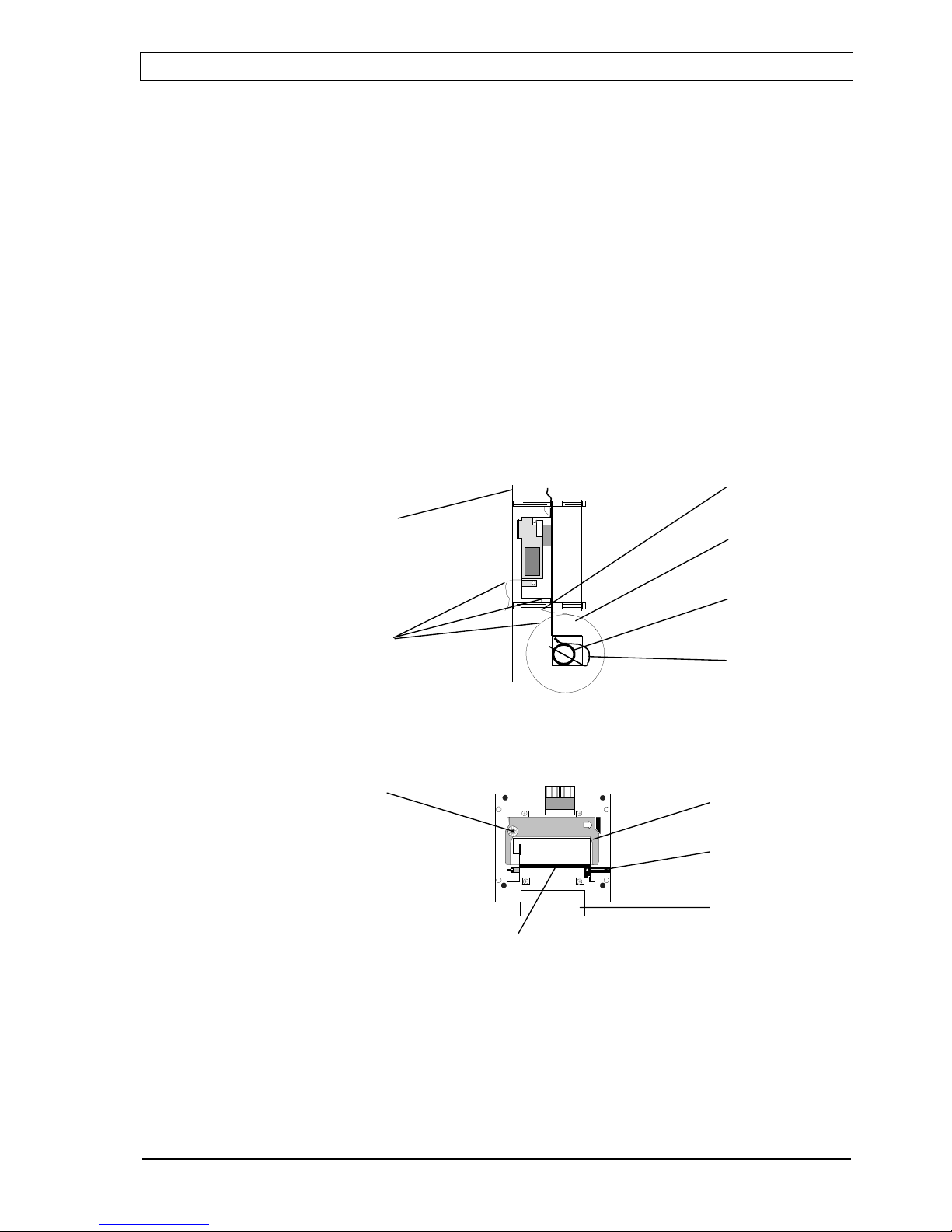
Appendix B -
Replacing the paper roll in the optional printer
If a printer is fitted, it is located on the inside of the control panel inner door.
A: Open the control panel inner door.
B: Remove the empty roll by releasing the locking clip on the right-
hand side of the paper roll shaft, and pull the shaft out to the other
side (See fig. A).
C: Let the free end of the new paper roll point downwards. Bend it and
guide it into the printer paper slot in the lower end of the printer.
(See fig. A).
D: Bend the end of the paper in an arrow shape to simplify the import
into the printer paper slot.
E: Put the new paper roll in its correct place, insert the paper roll shaft
again and secure it by means of the locking clip.
Fig. A: Side view of the optional printer located at the rear side of the inner door.
Fig. B: Location of the finger screw on the optional printer (front view).
F: Feed the paper manually through the printer by turning the finger
screw. (See fig. B)
G: Close the control panel inner door.
Paper slot
Paper roll
Paper roll
shaft
Locking clip
(left hand)
Control panel
inner door
Printer paper
Ribbon container
Finger screw
Paper roll
Slot for ribbon
Adjusting
wheel for
ribbon

BS100 DYFI Operators handbook
P-BS100/FE - Rev.F / Doc/ 980114 48 Autronica Fire and Security AS
Appendix C -
Multiple BS-100/-Control panels with common
repeater units (BU-100/101/70)
There is no communication between the individual BS-100 control panel.
Each individual BS-100 control panel gives warning about its own condition
and relays this to the common BU-units.
(BU-units, common name for repeater units BU-100, BU-101 and BU-70).
- Custom designed texts within each BS-100 control panel is
presented to all BU-units.
- The EA-computer has to contain a special system program for
comm. with BU-units.
- Digital in-/outputs can be used as supplement function from EA-.
The table below shows which operator buttons. Indication lamps are fitted to
the various BU-units.
Indication lamps BU-100 BU-101 BU-70
H1 Indicator lamp X X
H2 Indicator lamp X X
H3 Indicator lamp X X
Device(s) still in alarm cond. X X
Prewarning X X X
Fault X X X
Function disabled X X
Mains X X X
More alarms X X X
Operation buttons
More alarms X X X
Sounder silence X
Sounder silence (buzzer) X X
Reset X
A
BS-100
Fire alarm control
panel
BS-100
Fire alarm control
panel
BS-100
Fire alarm control
panel
EA-
Protocol
Interfacer
Display-unit
(BU-unit)
Display-unit
(BU-unit)
A
B
C
CL
CL
CL
Programversion in EA-:
P1-EAC4/A1-22
* Program variant 1XX
(ex. 103) promises that the
program is communicating
with BU-units.
Digital inputs
Digital outputs

BS100 DYFI Operators handbook
P-BS100/FE - Rev.F / Doc/ 980114 49 Autronica Fire and Security AS
C.1 Alarm /Prewarning / Fault /More alarms
BU-units can be programmed to present fire alarm, prewarning and fault
with text on the display.
C.1.1 Fire alarm from a BS-100
Fire alarm message (panel address, loop, detector no. or custom text) will
only appear in the display of the BS-100 control panel which has registered
the incident and on the BU-units.
BU-100 will present alarm from all detectors, BU-70 and BU-101 can be
programmed into presentation zones.
Fire alarm message will only appear in the display of the BS-100 control
panel even if the door is open.
Internal buzzer and FIRE indication lamps will be activated on the BS-100
control panel which registered the fire alarm and on the BU-units.
Only the BMA-output on the control panel which registered the fire alarm
will be activated.
Only the control outputs on the BS-100 control panel which registered the
fire alarm will be activated.
Only the sounders connected to the control panel which registered the fire
alarm will be activated.
Alarm output on the EA- will be activated (output L57).
C.1.2 Prewarning
Prewarning message (panel address, loop, detector no. or custom text) will
only appear in the display of the BS-100 control panel which registered the
prewarning and on the BU-units.
If the front door is open on the BS-100 control panel, there will be no
message in the display or transmitted to the BU-units. The message will
appear when the door is closed.
Internal buzzer and PREWARNING indication lamps will be activated on
the BS-100 control panel which registered the prewarning and on the BUunits.
Only the BMFO-output on the control panel which registered the
prewarning will be activated.
Prewarning output on the EA- will be activated (output L58).
!

BS100 DYFI Operators handbook
P-BS100/FE - Rev.F / Doc/ 980114 50 Autronica Fire and Security AS
C.1.3 Fault
Detector-/System faults registered on a BS-100 control panel will only give
message to that control panel and on the BU-units. On the BS-100 control
panel the fault message will appear in the display. Internal buzzer and
FAULT indication lamp will also be activated.
If the door is open on the BS-100 control panel, there will be no fault
message in the display. The message will appear when the door is closed.
On the BU-units the internal buzzer and the FAULT indication lamp will be
activated. (No text in the display)
Fault output (not comm.fault) on the EA- will be activated (output L59).
Only the BMA-output on the control panel which registered the fault will be
activated.
If a communication failure between the BS-100 control panel and the EA
occurs, the fault message will be printed out on the printer on the BU-units.
Comm.fault output BS-/EA- will be activated (output L61).
When there is a communication failure between the EA and the BU-units
the comm.fault output EA-/BU- will be activated (output L62).
C.1.4 More alarms
The "MORE ALARMS" indication lamp will light on the BS-100 control
panel which is registering more than one alarm. When there are two alarms
on different BS-100 control panels, the "MORE ALARMS" indication lamp
will not light.
The "MORE ALARMS" indication lamp on the BU-units will light if there
are more than one alarm registered in the system. Two alarm from two
different BS-100 control panels will activate the "MORE ALARMS"
indication lamp on the BU-units.
C.1.5 Device(s) still in alarm cond.
After "RESET" the "DEVICE(S) STILL IN ALARM COND." indication
lamp may light on the BS-100 control panels which still has addresses in
alarm condition. If this lamp lights on one of the BS-100 control panels, it
will also light on the BU-units.

BS100 DYFI Operators handbook
P-BS100/FE - Rev.F / Doc/ 980114 51 Autronica Fire and Security AS
C.1.6 Function disabled
The "FUNCTION DISABLED" indication lamp will only light on the
control panel which is partly disabled. If this lamp is illuminated on one of
the BS-100 control panels, it will also light on the BU-units.
C.1.7 Indication lamps H1, H2, H3
The indication lamps H1, H2 and H3 on the BS-100 control panel are
controlled separately.
The indication lamps H1, H2 and H3 on the BU-units are controlled from
the control outputs on the EA 2/3 (input L51, 52, 53).
C.2 Operation
C.2.1 SOUNDER SILENCE
C.2.1.1 From fire alarm control panel
When "SOUNDER SILENCE" button on the BS-100 control panel which
has registered the alarm is operated, all alarm devices connected to this
control panel and the internal buzzer on the BU- units are switched off.
If another BS-100 control panel also is in alarm condition, "SOUNDER
SILENCE" also must be operated at that control unit.
C.2.1.2 From EA- or BU-100
If the "SOUNDER SILENCE" is operated from the EA 1/2/3 (separate
input) or the BU-100, all alarm devices and internal buzzers on all BS-100
control panels will be silenced.
C.2.2 Reset
C.2.2.1 From fire alarm control panel
When operating the "RESET" on a control panel in abnormal condition (all
other control panels are in normal condition), this will reset the entire
system.
If another BS-100 control panel is in abnormal condition, operating of the
"RESET" will only reset the control panel which is operated.
To reset the entire system (BS-100 and BU-units) operate the last control
panel in abnormal condition.
C.2.2.2 From EA- or BU-100
Operating of the "RESET" from EA 1/2/3 or BU-100 will reset the entire
system.

BS100 DYFI Operators handbook
P-BS100/FE - Rev.F / Doc/ 980114 52 Autronica Fire and Security AS
C.2.3 More alarms
When operating the "MORE ALARMS" on the individual BS-100 control
panels, it is only possible to scroll alarms registered in that particular BS100 control panel which has been operated.
When operating the "MORE ALARMS" on BU-units, it is possible to scroll
alarms registered in the entire system.
C.3 Disable / Restore
Disablements on a BS-100 control panel will activate "FUNCTION
DISABLED" only on this control panel and on the BU-units.
Disablements will be stored in "STORED-EVENTS" and only showed in
the menu "SHOW-STATUS DISABLEMENTS" on the control panel where
the disablement was carried out.
Disablements / restorations of address, zone, controls, sounders and Fire
brigade can only be carried out on the individual BS-100 control panel.
C.4 System
C.4.1 Sensitivity
Sensitivity control must be carried out at each individual BS-100 control
panel.
C.4.2 Internal
The real-time clock in BS-100 control panels has to be set manually via
menu.
The EA- clock will be set equal to the clock in control panel with address A.

BS100 DYFI Operators handbook
P-BS100/FE - Rev.F / Doc/ 980114 53 Autronica Fire and Security AS
Appendix D -
BS-100 master / Control unit with BS-60 slaves
When a condition (fire, fault, prewarning) is registered on a control panel
(BS-100/BS-60), the indication lamps on the panel front will light, the
outputs will be activated etc. in the normal way.
The custom texts presented in the display on both BS-100 and BS-60 have
to be manually programmed in both control panels.
There is no communication between the BS-60 control panels.
D.1 Alarm /Prewarning / Fault/ More alarms
D.1.1 Fire alarm
Fire alarm from the BS-100 control panel is only registered on the BS-100
control panel. There will be no display of info. on the BS-60 control
panel(s).
Fire alarm from a BS-60 control panel is registered on the relevant BS-60
control panel and on the BS-100 control panel.
There will be no display of info. on any other BS-60 control panel.
BS-60
Fire alarm
control panel
1 loop
BS-60
Fire alarm
control panel
1 loop
BS-60
Fire alarm
control panel
1 loop
BS-60
Fire alarm
control panel
1 loop
BS-100
Main fire alarm
control panel
KDL-26
Comm.
line splitter
CL
CL
CL
CL
CL

BS100 DYFI Operators handbook
P-BS100/FE - Rev.F / Doc/ 980114 54 Autronica Fire and Security AS
D.1.2 Prewarning
Prewarning from the BS-100 control panel is only registered on the BS-100
control panel. There will be no display on the BS-60 control panel(s).
Prewarning from a BS-60 control panel is registered on the relevant BS-60
control panel and on the BS-100 control panel.
There will be no display of info. on any other BS-60 control panel.
D.1.3 Fault
(The BS-100 control panel will look at the BS-60 control panels as ordinary
loops).
Fault from the BS-100 control panel is registered on the BS-100 control
panel. There will be no display of info. on BS-60 control panel(s).
Fault from a BS-60 control panel is registered on the relevant BS-60 control
panel and on the BS-100 control panel.
D.1.4 More alarms
More alarms from the BS-100 control panel will only be registered on the
BS-100 control panel. There will be no display of info. on the BS-60
control panel(s).
More alarms from a BS-60 control panel will also be registered as more
alarms on the BS-100 control panel. There will be no display of info. on
other BS-60 control panels.
2 alarms from 2 different BS-60 control panels will be registered as more
alarms on the BS-100 control panel.

BS100 DYFI Operators handbook
P-BS100/FE - Rev.F / Doc/ 980114 55 Autronica Fire and Security AS
D.2 Operating
D.2.1 Sounder Silence
The "SOUNDER SILENCE" function will be dependent upon how it is
configured within each of the BS-60 control panels.
When operating the "SOUNDER SILENCE" on the BS-100 control panel,
all alarm devices will be switched off (also devices connected to the BS-60
control panels).
If the "SOUNDER SILENCE" function is set to "OFF", the "SOUNDER
SILENCE" can only be operated from the BS-100 control panel.
If the "SOUNDER SILENCE" function is set to "ON", the "SOUNDER
SILENCE" can be operated from both the BS-60 and the BS-100 control
panel.
If the "SOUNDER SILENCE" is operated from a BS-60, alarm devices
connected to the BS-60 control panel which is operated, will be switched
off.
D.2.2 Reset
The "RESET" function will also be dependent upon how it is configured
within each of the BS-60 control panels.
When operating the "RESET" from the BS-100 control panel, the entire
system will be reset.
If the "RESET" function is set to "OFF", the "RESET" can only be operated
from the BS-100 control panel.
If the "RESET" function is set to "ON", the "RESET" can be operated from
both the BS-100 and the BS-60 control panel.
When operating the "RESET" from the BS-60 control panel, only the BS-60
which is operated will be reset.

BS100 DYFI Operators handbook
P-BS100/FE - Rev.F / Doc/ 980114 56 Autronica Fire and Security AS
D.3 Disable / Restore
When disabling on a BS-60 control panel, the "FUNCTION DISABLED"
indication lamp will light only on this control panel.
This will be logged in "SHOW-STATUS DISABLEMENTS" and in
"STORED-EVENTS" only on the current control panel.
It is advisable to disable / restore BS-60 addresses from the BS-100.
D.3.1 Address
The BS-100 can disable/restore all addresses in the system.
The BS-60 can only disable/restore addresses connected to it.
D.3.2 Zone
Only zones defined in the BS-100 control panel can be disabled/restored
from the BS-100 control panel. Zones defined in a BS-60 control panel can
be disabled/restored only at the relevant BS-60 control panel.
D.3.3 Controls
Controls connected to the BS-100 control panel can only be
disabled/restored from the BS-100 control panel.
Controls connected to the BS-60 control panel can only be disabled/restored
at the relevant BS-60 control panel.
D.3.4 Sounders
Sounders connected to the BS-100 control panel can only be
disabled/restored from the BS-100 control panel.
Sounders connected to a BS-60 control panel can only be disabled/restored
at the relevant BS-60 control panel
D.3.5 Fire brigade / fighters
BMA, BMF, BMFO outputs from the BS-100 control panel can only be
disabled/restored from the BS-100 control panel.
BMA, BMF, BMFO outputs from the BS-60 control panel can only be
disabled/restored at the relevant BS-60 control panel.

BS100 DYFI Operators handbook
P-BS100/FE - Rev.F / Doc/ 980114 57 Autronica Fire and Security AS
D.4 System
D.4.1 Sensitivity
All addresses in the system (including those connected to the BS-60 control
panel(s)) can be interrogated from the BS-100 control panel.
From the BS-60 control panel it is only possible to interrogate the addresses
connected to it.
D.4.2 Internal
In all control panels the internal clock has to be set manually.
The internal clocks of all control panels are independent and must be set
individually.

BS100 DYFI Operators handbook
P-BS100/FE - Rev.F / Doc/ 980114 58 Autronica Fire and Security AS
Autronica Fire and Security AS is an international company, based in Trondheim,
Norway and has a world-wide sales and service network. For more than 40 years
Autronica’s monitoring systems have been saving lives and preventing catastrophes
on land and at sea. Autronica Fire and Security’s most important business area is fire
detection & security. Autronica Fire and Security stands for preservation of
environment, life and property.
Quality Assurance
Stringent control throughout Autronica Fire and Security assures the excellence of
our products and services. Our quality system conforms to the Quality System
Standard NS-EN ISO 9001, and is valid for the following product and service
ranges: marketing, sales, design, development, manufacturing, installation and
servicing of:
• fire alarm and security systems
• petrochemical, oil and gas instrumentation systems for monitoring and control
In the interest of product improvement, Autronica Fire and Security reserves the
right to alter specifications according to current rules and regulations.
Autronica Fire and Security AS
Fire and Security, Trondheim, Norway. Phone: + 47 73 58 25 00, fax: + 47 73 58 25 01.
Oil & Gas, Stavanger, Norway. Phone: + 47 51 84 09 00, fax: + 47 51 84 09 99.
Autronica Industrial Ltd., Watford, United Kingdom. Phone: 1923 23 37 68
fax: 1923 22 55 77.
 Loading...