


Technical Documentation: Fire Detectors used in hazardous areas
Technical Documentation
Fire Detectors
used in hazardous areas
Analogue Addressable system type BS-100
with zener barrier unit type BZ-32
Conventional system type BX-40
with zener barrier type BZ-20S
P-DET/Ex/RCE
Autronica Fire and Security AS
N-7483 Trondheim.
Phone: +47 73 58 25 00, fax: +47 73 58 25 01
Autronica Industrial Ltd., Watford, England
Phone: 1923 23 37 68, fax: 1923 22 55 77.
Oil & GAs AS, Stavanger, Norway
Phone: +47 51 84 09 00, fax: +47 51 84 09 49
P-DET/EX/RCE/PM5/GKa/110995 1 Autronica Fire and Security AS

Technical Documentation: Fire Detectors used in hazardous areas
Table of contents:
Abbreviation, related to fire equipment in ex-area 3
1 General part 4
1.1 Danger of explosion 4
The triangle of explosion 5
1.2 Ex-classifications 6
1.3 Labelling electrical equipment 9
1.4 Limiting temperatures 10
1.5 Installing fire alarm equipment in hazardous area 11
1.6 Installation of Autronica fire alarm systems in hazardous areas 11
1.7 Rules regarding potential equalization, PE, to fire detectors
in hazardous areas 13
1.8 Potential equalizations: PE on ships 14
1.9 Installation data - 15
Limitations w.r.t capacitance in cable and detectors/call-points
connected to zener barrier type Z667/Ex
(part of zener barrier BZ-20/S and BZ-32)
2 Analogue addressable system type BS-100 16
2.1 Zener barrier unit type BZ-32 16
2.2 BZ-32, connection diagram, drawing BZ-049 (BZ-047) 17
2.3 BZ-32, functional description, drawing BZ-044 18
3 Conventional system type BX-40 24
3.1 Zener barrier unit type BZ-20/S 24
3.2 BZ-20/S, connection diagram, drawing BZ-076 (BZ-078) 25
3.3 Arranging Ex-loop 25
3.4 BZ-20/S, functional description, drawing BZ-053 25
P-DET/EX/RCE/PM5/GKa/110995 2 Autronica Fire and Security AS

Technical Documentation: Fire Detectors used in hazardous areas
Abbreviation, related to fire alarm equipment in Ex area.
Abbreviation: Explanation.
ANSI : American National Standard Institute.
BASEEFA: British Approvals Service for Electrical Equipment
CENELEC: European Commitee for Electrotechnical Standardization.
DNV: (Det Norske Verital) Norwegian Approval Institute.
EEx: Explosion protection to European standards.
EN: Norms edited by CENELEC.
FM: Factory Mutual (USA).
IEC: International Electrotechnical Commission
ESBN: International Standard Book Number.
NEC: National Electrical Code (USA).
NEK: (Norsk Elektroteknisk Komite)
in Flammable Atmospheres.
(Prototype for EN-norms).
Norwegian Electrotechnical Commitee.
NEMKO: (Norsk Elektrisk Materiellkontroll)
Norwegian Electrical Material Control.
NFPA: National Fire Protection Association (USA).
PA/PE: Equipotential terminal.
PTB: West German Approval Organization
(Physikalisch Technische Bundesanstalt).
VDE: West German Approval Organization
(Verband Deutcher Elektrotechniker).
P-DET/EX/RCE/PM5/GKa/110995 3 Autronica Fire and Security AS

Technical Documentation: Fire Detectors used in hazardous areas
2
2
2
2
2
2
2
2
2
2
2
2
2
2
2
2
2
2
2
2
2
2
2
2
2
2
2
2
2
2
2
2
2
2
2
2
2
2
12345678901234567
1
7
1
7
1
7
1
7
1
7
1
7
1
7
1
7
1
7
1
7
1
7
1
7
1
7
1
7
1
7
1
7
1
7
1
7
1
7
1
7
1
7
1
7
1
7
1
7
1
7
1
7
1
7
1
7
1
7
1
7
1
7
1
7
1
7
1
7
1
7
1
7
1
7
1
7
1
7
1
7
1
7
1
7
1
7
1
7
1
7
1
7
1
7
1
7
1
7
1
7
1
7
1
7
1
7
1
7
1
7
1
7
1
7
1
7
1
7
1
7
1
7
12345678901234567
General part
Danger of
explosion
1 General part
1.1 Danger of explosion.
An explosion is a very rapid combustion, depending on the access of oxygen.
More oxygen accelerate the combustion. Some compounds, such as powder
and dynamite, has oxygen "baked" into the substance.
This description is concerning hazardous gases, and different ways of preventing these from exploding.
The emphasis is to prevent electrical energy from getting access to the hazardous area in an amount big enough to trigger a fire and consequently an
explosion.
Three ingredients are necessary to perform an explosion. These three ingredients are:
Explosive gas, oxygen (air) and igniting energy.
If one of these ingredients is missing, completely or partly, an explosion can
not take place.
The curve below shows how these ingredients affect the hazard of explosion.
Specially observe that for gas/air mixtures a value exist where minimum
igniting energy is necessary for an explosion to take place. Both more and less
concentrate mixtures will need more igniting energy to get the gas exploding.
To strong, and too weak concentrations are not exploding.
Igniting
energy
2345678901
2345678901
2345678901
2345678901
2345678901
2345678901
2345678901
2345678901
2345678901
2345678901
2345678901
2345678901
2345678901
2345678901
2345678901
2345678901
2345678901
2345678901
2345678901
2345678901
2345678901
2345678901
2345678901
2345678901
2345678901
2345678901
2345678901
2345678901
2345678901
2345678901
P-DET/EX/RCE/PM5/GKa/110995 4 Autronica Fire and Security AS
2345678901
2345678901
2345678901
2345678901
2345678901
2345678901
2345678901
2345678901
0 ...............................................% gas.............................................. 100
100 ..............................................% Air..................................................0
Igniting energy
necessary for
explosion.
To weak
mixture
Minimum
igniting energy
Too strong
mixture
234567890123456
234567890123456
234567890123456
234567890123456
234567890123456
234567890123456
234567890123456
234567890123456
234567890123456
234567890123456
234567890123456
234567890123456
234567890123456
234567890123456
234567890123456
234567890123456
234567890123456
234567890123456
234567890123456
234567890123456
234567890123456
234567890123456
234567890123456
234567890123456
234567890123456
234567890123456
234567890123456
234567890123456
234567890123456
234567890123456
234567890123456
234567890123456
234567890123456
234567890123456
234567890123456
234567890123456
234567890123456
234567890123456
234567890123456
234567890123456
234567890123456
234567890123456
234567890123456
234567890123456
234567890123456
234567890123456
234567890123456
234567890123456
234567890123456
234567890123456
234567890123456
234567890123456
234567890123456
234567890123456
234567890123456
234567890123456
234567890123456
234567890123456
234567890123456
234567890123456
234567890123456

Technical Documentation: Fire Detectors used in hazardous areas
The triangle of explosion.
oxygen
igniting energy
oxygen gas
oxygen
igniting energy
The equilateral, big triangle, may be considered to represent a case with
optimum gas/oxygen relation, i.e. minimum ignition energy is required to
trigger an explosion. If the ignition energy is high enough, an explosion will
take place.
gas
igniting energy
gas
oxygen
gas
igniting energy
The small triangle to the left has the same values of oxygen and igniting
energy as in the equilateral, big triangle, but the content of gas is too small to
perform an explosion.
I.e. the gas/air mixture is too weak for an explosion to take place.
The remaining two small triangles should be self-explaining, showing the
cases with too low igniting energy and too little oxygen respectively.
P-DET/EX/RCE/PM5/GKa/110995 5 Autronica Fire and Security AS

Technical Documentation: Fire Detectors used in hazardous areas
Ex-
classifications
1.2 Ex-classifications
The risk of explosion is different for different gas types and areas where the gas
is expected to be present. Therefore classifications of gases into Groups and
areas into Zones are necessary.
Group classification is concerning the type of gas which is (or is expected to
be) present in the hazardous area. Two criteria are of value when the gas is to
be classified.
a) The gas grade of explosion hazard, and
b) The ignition energy necessary to make the gas explode.
Zone classification is, as the name indicates, based upon the zones surrounding
the gas source.
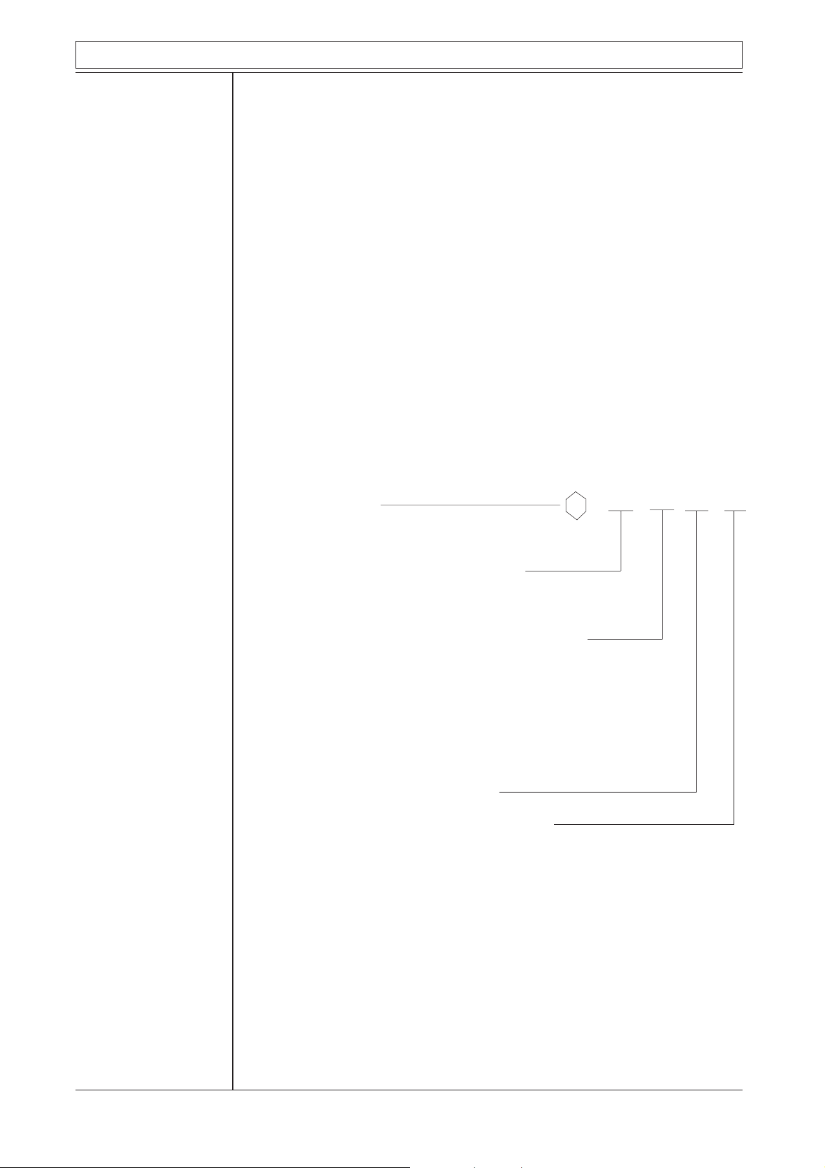
Classifications are indicated by type description. The example below shows the
type:
Exib/IIC, which is, by the way, the claims Autronica set to the products used in
hazardous areas.
Ex - means that the equipment is intended for use in hazardous area.
(EEx is European standard)
i - means that the equipment is intrinsically safe.
b - means that the equipment must be used in zone 1 or 2.
(a - is zone 0, 1 and 2)
II - means that the equipment is intended for group II, which covers
nearly all purposes. (Group I is Mining Industry, mainly).
C - means that the equipment is build to withstand the most extreme
claims with respect to safety. (Ignition energy less than 20 µ -
joule and surface temperature less than 85°C).
The drawing below shows the distribution of zones around gas sources. The
right illustration shows a simple concentric arrangement, while the left one
illustrates a tank under loading or unloading. The expansion of zones 1 and 2
along the base is due to the fact that the gas has a higher density than the air.
In most of the industry buildings where danger of explosion exist, the main part
of the hazardous area is characterised as Zone 2.
Note that USA and Canada have different zone classification, such that their
"Division 1" covers Zone 0 and Zone 1. "Division 2" covers Zone 2.
P-DET/EX/RCE/PM5/GKa/110995 6 Autronica Fire and Security AS

Technical Documentation: Fire Detectors used in hazardous areas
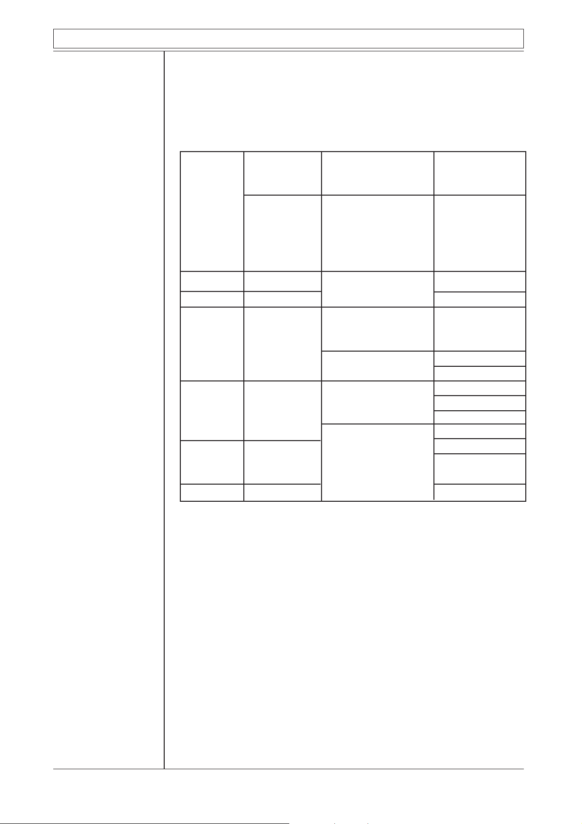
The table below shows the different forms of protection against gas explosion,
in abbreviations and explanations. The latter is presented in the plain languages
most used by Autronica personnel, handling fire alarm problems.
Plain language explanation in:
Abbreviation Norwegian English German
Exd Eksplosjonssikker Flame proof Druckfeste Kapselung
utførelse
Exe Tennsikker utførelse Increased safety Erhöhte sicherheit
Exm Innstøpt utførelse Moulded Vergusskapselung
Exn Utstyr for sone 2 Equipment for
Zone 2.
Exs Spesialutførelse Special construction Sonderschutz
Exi Egensikker utførelse Intrinsically safe Eigensichere
Exia Sone 0, 1 og 2 Zone 0, 1 and 2 Betribsmittel
Exib Sone 1 og 2 Zone 1 and 2
Exp Overtrykkskapsling Pressurized enclosure Überdruckkapselung
Exo Oljefylt Oil immersed Ölkapselung
Exq Sandfylt Sand filled Sandkapselung
Note that all Ex-determinations, except Exi, Exia, and Exib are concerning
apparatuses.
Intrinsic safety.
(Concerns circuits, which may include several apparatuses).
Intrinsically safe equipment has limited supply of electrical energy, so that any
spark created has too low energy to ignite the gas.
Also no part of the equipment surface shall be able to reach a temperature
greater than the igniting temperature of the gas. (Which is, or may be expected
to be present.) In order to be able to perform this energy limitation, energy
barriers are necessary to limit the supply of electrical energy to the hazardous
area. Such energy barriers are built up by means of zener diodes, and therefore
they are given the name Zenerbarriers.
Exi-equipments are arranged in two main groups, Group I and Group II.
The latter, which is the one being concerned in this description is again divided
in three parts, namely: Group IIA, Group IIB, and Group IIC. (Group I is
concerning Mining Industry, mainly).
Equipment may, of course, be used for less hazardous area than what it is built
for.
P-DET/EX/RCE/PM5/GKa/110995 7 Autronica Fire and Security AS
Technical Documentation: Fire Detectors used in hazardous areas
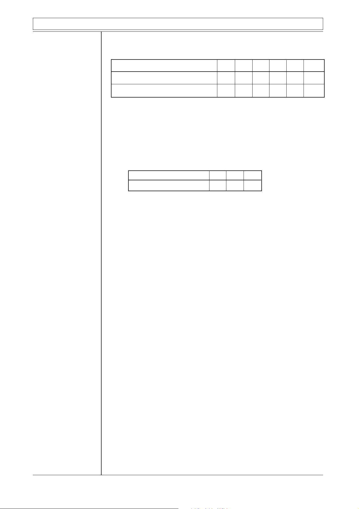
The table below shows the relation between temperature grades, equipment
surface temperature, and gas ignition temperature.
Temperature grades T1 T2 T3 T4 T5 T6
Max. surface temperature °C 450 300 200 135 100 85
Gas min. ignition temperature °C 450 300 200 135 100 85
Note that maximum surface temperature must not, at any occasion (even with
fault) exceed the igniting temperature of the actual gas.
The table below shows the relationship between different gas groups and
allowed igniting energy.
Gas-group IIA IIB IIC
Igniting Energy in µ Joule 200 60 20
NOTE that values given for igniting energy are limits, and therefore safety
factors must be introduced. Values may be selected from the CENELEC norm
EN-50020.
In order to calculate igniting energy, the following two equations are actual:
Energy stored in a capacitor (capacitance) is: EC = ½ C U
Energy stored in a coil (inductance) is: EL = ½ L I
2
2
Where: EC and EL are energies in Joules.
C is capacitance in Farads.
U is voltage in Volts.
L is inductance in Henry.
I is current in Ampere.
Note that wires represents both capacitance and inductance, and this phenomena must be taken into consideration for long wire installations at the hazardous
side of zenerbarriers.
P-DET/EX/RCE/PM5/GKa/110995 8 Autronica Fire and Security AS
Technical Documentation: Fire Detectors used in hazardous areas
1.3 Labelling electrical equipment
Electrical equipment intended for use in hazardous area, shall be properly
labelled in accordance with claims brought forward by national or international
authorities.
The label shall, according to, e.g. EN-50020, contain the symbol Ex, the form
of protection (see table page 7, Abbreviation) e.g. "i", gas group (see table
page 8) e.g. "IIB", and eventually the class of temperature e.g. "T3". This is
true if the maximum ambient temperature is diverging from + 40°C.
The label also shall show the name or logo of test- and approving institution
and test approval statement.
For small electrical equipment, with limited space, reduced labelling may be
accepted.
The label shall then include:
The symbol Ex, name of Test institution (test approval), and Manufacturer.
Description: Labelling code:
Approval sign for apparatus certified by
an institution within the European Common
Market, EC: Ex EEx i a/b IIB T3
Sign indicating that the equipment is produced
according to The European Norm (EN)
EEx means: "Explosion protection to
European standards"
Intrinsically safe performance; ia or ib (see page 6)
ia: withstands 2 faults with safety factor = 1
or 1 fault with safety factor = 1,5
ib: withstands 1 fault with safety factor = 1,5
or 1 fault with safety factor = 1
and no unprotected conductor
Group: IIA, IIB or IIC (see page 8)
Temperature class: T1, T2, T3, T4, T5 or T6
(see page 8)
This example is made according to the
CENELEC norm.
P-DET/EX/RCE/PM5/GKa/110995 9 Autronica Fire and Security AS
Technical Documentation: Fire Detectors used in hazardous areas
1.4 Limiting temperatures
The table shows limiting temperatures for electrical equipment which may be
mounted in hazardous area, according to regulations made by IEC, VDE and
NEC.
The temperature limits are valid for parts of the equipment, and for every
possible condition.
Classification Classification Classification
according to: according to: according to:
IEC/CENELEC VDE 170/0171/2.61 NEC(USA/Canada)
Igniting
temperature Temp. Temp. Igniting Max. Max. Temp. Gas
for gases class limit group temp. temp. identi- igniting
°C °C °C °C fication temp.
Contin- Short
ously term
450 T1 450 G1 T1 450
300 T2 300 360 400 T2 300
G2 270 T2B 260
240 T2C 230
200 T3 200 T3 200
180 T3A 180
G3 T3B 165
160 T3C 160
135 T4 135 T4 135
G4 125 T4A 120
110
100 T5 100 G5 90 T5 100
85 T6 85 80 T6 85
T2A 280
T2D 215
P-DET/EX/RCE/PM5/GKa/110995 10 Autronica Fire and Security AS

Technical Documentation: Fire Detectors used in hazardous areas
Installation fire
alarm equipment
in hazardous area
1.5 Installation fire alarm equipment in hazardous area.
This description can not, of course, include every possible installation of
electrical equipment in hazardous area.
Therefore, the most common rules are mentioned below:
In power distribution systems with earthed zero terminal, the earth wire and the
zero terminal shall be kept insulated inside hazardous area. A common earthand zero wire (PEN-wire) is not allowed.
Comment:
Common earth- and zero-wire (PEN-wire) may be utilized for that part of the
distribution network outside the hazardous area.
Distribution systems with insulated zero wire must have an earth fault operating
switch breaking the circuit at a current of 500 mA, or have facility which by
audible or visible signal gives warning of earth fault in the system.
When an earth fault is given, the fault must be repaired immediately.
Earth wire must physically be situated in the same tube as the feeding wires.
(Separate earth wires are not accepted.)
Comment:
The claims do not exclude use of separate earth wire as equipotential connection in addition to common safety earth wire. Such equipotential connection
ought to be used for special exposed system parts, e.g. construction elements of
electrically conducting material, pipes etc. in order to avoid potential difference
and consequently danger of electrostatic charges.
Installation of
Autronica
fire alarm in
hazardous area
In addition to the comments above, it must be mentioned that the term
equipotential connection is differently abbreviated in different documents, such
that PA-, PE-, a.o.
In this document the term PE- is preferred.
1.6 Installation of Autronica fire alarm systems in
hazardous areas.
Several approval authorities have more or less equal norms to be the recommending and normgiving authorities respectively. But we must recommend you
to obtain the laws and regulations concerning your country, because slightly
different rules exists in different countries.
P-DET/EX/RCE/PM5/GKa/110995 11 Autronica Fire and Security AS

Technical Documentation: Fire Detectors used in hazardous areas
In this description the part regarding installation will be confined to our zener
barrier unit type BZ-32, mainly. This unit is built up by means of AC-zener
barrier as main component. The advantage of using this ac-barrier is explained
by the two sketches, and the associated description below:
Zener barrier type Z667/Ex
R1
R
S
R3
R2
Z1
PE
Z3
R4
Fig. 1 Fig. 2
Z2
Z4
F1
Positive
barrier
Negative
barrier
F2
Resistor
13
R1
4
R
S
Resistor
23
R2
Zener diodes
ZD1
ZD7
ZD4
Zener diodes
ZD2
ZD8 ZD9
ZD5
ZD3
ZD6
Fuse
F1
PE
Fuse
F2
11
2
21
Diagram fig.1 shows the connection of two zener barriers, one positive and one
negative, confining one zener barrier unit. This unit has been used for our fire
alarm detector lines (loops).
With no fault the arrangement is perfect, without any trouble. The PE- terminal
will then, electrically viewed, be situated midway between minus (-) and plus
(+), at the same potential as the earth terminal in the panel, approximately. The
PE-terminal and the panel's earth terminal must be connected together (outside
the hazardous area), and therefore an earth indication will be given by the
panel, if the PE-terminal is connected to minus (or plus). When the detector line
is disconnected by shorting the plus- and minus-wires (as in the BS-systems)
trouble will be introduced because then the zener barrier Z1 and Z2 will
connect the PE-terminal to minus.
Considering the same situation with ac-barriers (see fig. 2), it is easily shown
that the zener diodes ZD7, ZD8 and ZD9 will prevent the PE-terminal from
being connected to minus.
Data for zener barrier type Z667/Ex
Nominal Type Max. end to end Working voltage Max. voltage Fuse
Charact- no. resistance at 10mA leakage rating
eristics mA
18V 120W Z667/Ex 135.4W 14.5V 16.5V 50
18V 120W 135.4W 14.5V 16.5V 50
P-DET/EX/RCE/PM5/GKa/110995 12 Autronica Fire and Security AS

Technical Documentation: Fire Detectors used in hazardous areas
Rules regarding
potential
equalization, PE,
to fire detectors in
hazardous areas
1.7 Rules regarding potential equalization, PE, to fire
detectors in hazardous areas.
To avoid sparks between an intrinsically safe circuit and the surroundings the
use of a Potential Equalization is required. Normally this is done by a PE-
conductor grounded at the zener barrier.
We differ between insulated detectors (plastic housing) and detectors in
conducting metal housing.
Detectors in plastic housing are non-conducting.
We also differ between conducting and non-conducting surface for mounting.
For insulated detectors the following applies:
The PE-conductor shall only pass through.
Some detectors and junction boxes have separate, insulated terminals for the
PE-conductor. Some detectors have no special terminal for the purpose, and the
connections for continuity must be provided by the installer.
This applies when mounted on both conducting and non-conducting surface.
For detectors in conducting metal housings the following applies:
When mounted on non-conducting surface , e.g. concrete the PE-conductor
shall be connected to the inside of the housing.
Special terminal screws are provided.
When mounted on conducting surface, the PE-conductor shall be connected
to the inside of the housing.
The outside earth terminal screw shall be connected to the surface.
A special case is when mounted in all welded steel ships. According to
classification societies (e.g. Det Norske Veritas) the hull itself can be
regarded as a PE-conductor, and PE-cabelling can be omitted.
Detectors in conducting metal housings must have good connection to the hull.
If a screened cable is used, the screen can not be used as a PE-conductor.
The screen shall continously pass through all detectors and shall be
grounded at the zener barrier only.
Earthing of the zenerbarriere:
Onboard ships:
The earth terminal of the zener barrier unit shall be connected to earth
(ships hull) by a cable not less than 4mm
The cable resistance must not exceed 1 Ω.
Onshore:
As there are different regulations for different countries you should check the
local regulations.
An extract from BS5345 pt. 4 is printed here as an example:
"....to preserve the integrity of an intrinsically safe system (e.g. a diode safety
barrier earth, a transformer screen earth, a barrier relay frame earth) such
connections should be made to a high integrity earth in such a way as to ensure
that the impedance from the point of connection to the main power system earth
point is less than 1 Ω. This may be achieved by connection to a switch room or
simular earth bar or by the use of separate earth rods. The conductor used for
the connection should be equivalent to a copper conductor of 4 mm2 minimum
cross-sectional area.
2.
"The conductor used for the earth connection should be insulated to prevent
invasion of the earth by fault currents which might flow in metallic parts with
which the conductor should otherwise come into contact (e.g. control panel
frames etc.). It should also be given mechanical protection in places where the
risk of damage is high."
P-DET/EX/RCE/PM5/GKa/110995 13 Autronica Fire and Security AS

Technical Documentation: Fire Detectors used in hazardous areas
1.8 Potential equalizations: PE on ships.
Zenerbarrier A B C D
+
-
PE
Conducting wall etc.
A: Insulated sensor on non conducting wall:
PE-conductor only passing through.
B: Insulated sensor on conducting wall:
PE-conductor only passing through.
C: Metal sensor on conducting wall:
PE-conductor connected to inside of box. Outside earth screw
connected to wall.
D: Metal sensor on non conducting wall:
PE-conductor connected to box.
For an intrinsically safe circuit the main demands are:
+
-
PE
1: Voltage, current and energy has to be below certain values (depending on
gas types), so that any sparks due to shortening or breaking the circuit do
not ignite the gas mixture.
This may be achieved by the use of a Zener barrier and restrictions for
inductively and capacity.
2: To avoid sparks between the IS circuit and the surrounding the use of a
Potential Equalization is necessary.
Normally this is done by a PE-conductor, grounded at the zener barrier.
When disconnected it shall withstand 500 V to ground. In welded steel
ships however, according to "Det Norske Veritas", the hull itself may be
used as potential equalization conductor.
3: The temperature of any component in an IS-circuit shall be below a given
value, depending on the gas group.
P-DET/EX/RCE/PM5/GKa/110995 14 Autronica Fire and Security AS

Technical Documentation: Fire Detectors used in hazardous areas
1.9 INSTALLATION DATA
Limitations w.r.t. capacitance in cable and detectors/call-points connected to zener
barrier type Z667/Ex (part of zener barrier units BZ-20/S and BZ-32).
For an intrinsically safe circuit connected to a zener barrier, there is a limitation as to how large a capacitance
(C
) the circuit can hold. C
max
danger from explosion.
For zener barrier Z667/Ex, the values are:
for gas group IIC : C
for gas group IIB : C
for gas group IIA : C
The following parameters apply:
The total capacitance in the cable and detectors/call-points shall not exceed C
Max. number of units connected to each zenerbarrier in BZ-20 and BZ-32 is 10. The total capacitance in
each branch must not exceed C
Cable: Capacitance in cable varies with type, but if the value is unknown, use a value of 200 pF per
metre as maximum.
will vary depending on which gas group is present in the area where there is a
max
= 0.440 µF
max
= 1.32 µF
max
= 3.52 µF
max
.
max
.
max
Detectors: Equivalent capacitance (Ci /Ceq) is for different detectors/call-points, as set during testing/certifica-
tion by NEMKO.
Group IIA Group IIB Group IIC
BD-26/Ex: Ci = 36 nF
BD-27/Ex: Ci = 36 nF 10 10 10
BE-30/Ex: Ci = 80 nF 10 10 5
BE-34/Ex: Ci = 80 nF
BH-31A/Ex: Ci = 30 nF 10 10 10
BH-31A/S/Ex: Ci = 30 nF
BJ-20B/Ex: C
BJ-31/Ex: C
BF-35/Ex: C
BF-32M/Ex C
BF-52/Ex: C
BF-53/Ex: C
BF-33/Ex: C
BF-34/Ex: C
BN-35/Ex: C
BN-32M/Ex: C
≤ 0,2 µF10 6 2
eq
≤ 0,2 µF
eq
≤ 10 nF
eq
≤ 10 nF 10 10 10
eq
≤ 10 nF
eq
≤ 10 nF
eq
≤ 0,4 µF 8 3 1
eq
≤ 0,4 µF
eq
≤ 10 nF 10 10 10
eq
≤ 10 nF
eq
The number of detectors / call-points is calculated with a cable of 200 m (200 m x 200 pF).
Notes: 1 µF = 1.000 nF = 1.000.000 pF
E.g. for gas group IIC (C
= 0.440 µF) for a single zener barrier type Z667/Ex.
max
50 m cable (à 200 pF) = 10 nF
2 x BF-35/Ex (à 10 nF) = 20 nF
7 x BH-31A/Ex (à 30 nF) = 210 nF
1 x BJ-31/Ex (à 0.2 µF) = 200 nF
440 nF = 0.440 µF
P-DET/EX/RCE/PM5/GKa/110995 15 Autronica Fire and Security AS

Technical Documentation: Fire Detectors used in hazardous areas
Analogue
addressable
system BS-100
Zener barrier
unit type BZ-32
2 Analogue addressable system type BS-100
2.1 Zener barrier unit type BZ-32
Barrier unit BZ-32 is mainly intended to be used together with Autronica
addressable fire alarm systems. The main component is one ac-barrier (see page
12) for each branch for connection of detectors in hazardous area.
Each unit may contain from one to four ac-barriers, and may consequently be
loaded with the same numbers of branches as the unit contains ac-barriers.
Each branch may take up to ten addresses.
The type indication includes the number of acceptable branches, indicated by a
digit placed behind a diagonal at end of type indication.
E.g. BZ-32/3 means that the maximum number of branches which may be
connected to this unit is 3.
Do remember that the total numbers of addresses at one BS-loop must be
limited to 99.
Note!
Units listed below only, may be connected to the zener barrier unit type BZ-32/
n (n being any number from 1 to 4).
Smoke detector, optical type BH-31A/Ex and BH-31A/S/Ex
Smoke detector, ion-chamber type BJ-33/Ex (BJ-31/Ex)
Heat detector type BE-30/Ex
Heat detector type BE-34/Ex
Manual Call-point type BF-32M/Ex
Manual Call-point type BF-33/Ex
Manual Call-point type BF-34/Ex
Manual Call-point type BF-35/Ex
Interface unit type BN-35/Ex to which
heat detector type BD-26/Ex (BE-26/Ex) and
heat detector type BD-27/Ex (BE-27/Ex may be connected.
BD-26/Ex (BE-26/Ex) and BD-27/Ex (BE-27/Ex) are conventional heat
detectors.
In order to limit the current consumption, none of these units are equipped with
alarm indicator (LED).
The four first mentioned detectors may, as described above, be connected to
one branch in number of maximum 10 units.
BN-35/Ex or BF-35/Ex must have the highest address numbers on the
branch.
1)
1)
This is purely estimated from an electrotechnical point of view. Other criterias
to be estimated are gas group and total capacitance, Ceq.
See page 15.
P-DET/EX/RCE/PM5/GKa/110995 16 Autronica Fire and Security AS

Technical Documentation: Fire Detectors used in hazardous areas
BZ-32,
connection
diagram
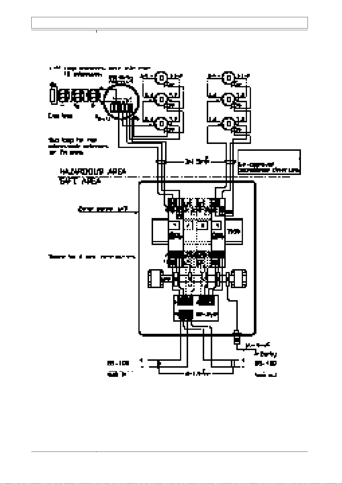
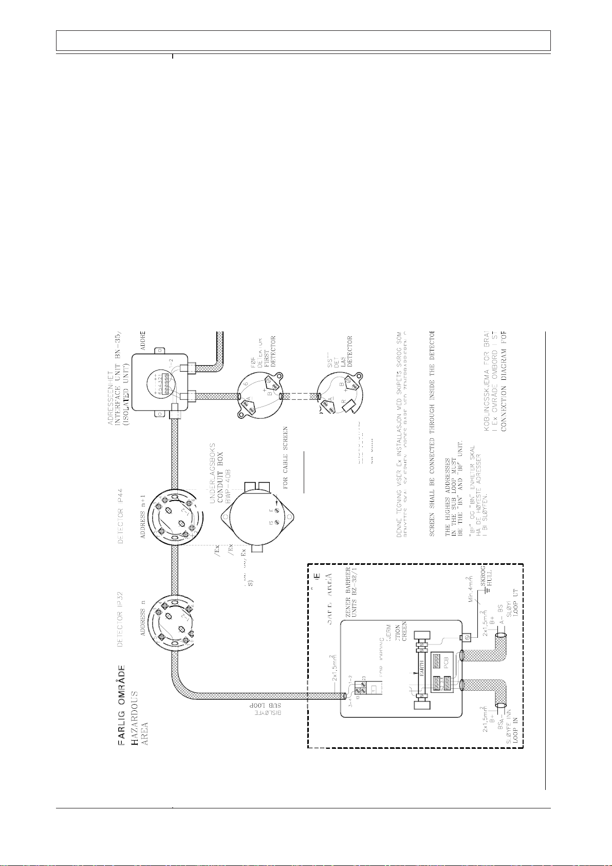
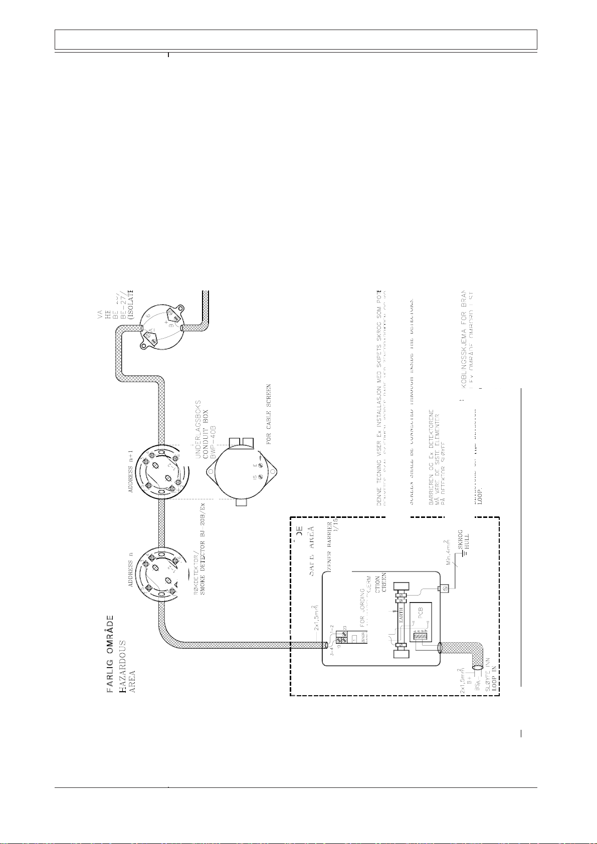
2.2 BZ-32, connection diagram, drawing BZ-049A (BZ-047A)
The diagram is separated in two main parts by a dot-dash-line. The components
located above that line is mounted in the hazardous area, and must be approved
for that purpose. At the projecting period it is important to place as little as
possible of the total equipment in the hazardous area.
Detectors which are operating independent of interface unit type BN-35/Ex
and are equipped with separate addresses, are marked with capital "D".
Conventional detectors, which need interface unit BN-35/Ex, are marked with
small "d" and all these detectors will have the same address number.
Note that, of course, all detectors must be approved for mounting inside
hazardous area, i.a. being marked B--/Ex.
Note also that the address number of BNB-35/Ex is given (n + 1) because this
unit (or BF-35/Ex) must be given the highest number of that branch.
Units loaded below the dot-dash-line are common Autronica fire alarm equipments. The equipotential line is marked with PE and is connected to terminal
marked 4 on the zener barrier unit.
Note that the equipotential terminal, (marked 4 on the ac-barrier unit) must not
be connected to the system earth inside hazardous area. These two terminals
are, however, shorted inside the ac-barrier unit itself.
On branch no. 1 an interface unit type BNB-35/Ex is shown in detail for both
the input terminals "1 + 2" and "3 - 4", and the sub-loop, SL's connection to
terminals 5(-) and 6(+).
The sub-unit BNB-35/Ex is used for call-point BF-35/Ex and interface unit
BN-35/Ex which is the one shown on this drawing.
The manual call-point, BF-35/EX, has no possibility for sub-loop connection.
(The terminals 5 and 6 are used for the push-button, which is to be manually
operated.)
(The highest address number, which on the drawing BZ-049A is given to an
analogue addressable detector is "n", and unit BNB-35/Ex is given the address
number "n + 1")
Also remember that here must the equation; n ≤ 9 be satisfied.
Zener barrier unit type BZ-32/1 contains 1 unit type Z-667/Ex
Zener barrier unit type BZ-32/2 contains 2 units type Z-667/Ex
Zener barrier unit type BZ-32/3 contains 3 units type Z-667/Ex
Zener barrier unit type BZ-32/4 contains 4 units type Z-667/Ex
P-DET/EX/RCE/PM5/GKa/110995 17 Autronica Fire and Security AS

Technical Documentation: Fire Detectors used in hazardous areas
BZ-32
function
description
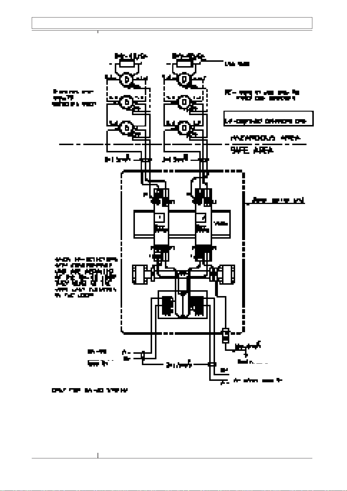
2.3 BZ-32 functional description, drawing BZ-044C
This diagram shows, in detail, how the current flow in the hazardous area is
limited to an acceptable value. On page 12 you will find diagram and description of the barrier Z-667/Ex where the detector line (loop) is represented by a
resistor "RS".
The potential equalization terminal is, inside the barrier Z-667/Ex, shorted to
the system "earth".
Only one of the four possible branches is illustrated. The other branches, (1 to
3) would have been drawn in an equal manner. The following functional
description is referring to branch number one.
The current through the branch is fed from plus (1 + 2), through the emitter base resistor R1, through the barrier Z-667/Ex terminals 21 to 23, through the
detectors "D" (which are parallel connected in a numbers of 1 to 10), through
the barrier Z-667/Ex terminals 13 to 11, and from there to minus (3 - 4).
The emitter - base resistor R1 is given a value to obtain a suitable voltage drop
so the transistor V1 does not conduct if none of the detectors is conducting.
The signal answer current, caused by any of the detectors, will increase the
voltage drop across R1, causing transistor V1 to conduct, passing a much greater
current through resistor R2. This causes the greater part of the signal current to
pass through the transistor and it's collector resistor R2.
In this way the necessary signal current through any of the detectors is limited
to a value which is acceptable for consumption inside the hazardous area.
(Accepted by the zener barrier's internal resistance.
All (maximum 4) branches are functioning in the same way, and perform signal
on the same terminal bloc, X1.
Observe that each detector; D1, D2 etc. to Dn are individually addressed.
P-DET/EX/RCE/PM5/GKa/110995 18 Autronica Fire and Security AS

P-DET/EX/RCE/PM5/GKa/110995 19 Autronica Fire and Security AS
SAFE AREA
CONNECTIONS ONLY.
HAZARDOUS AREA
CONNECTIONS ONLY.
Technical Documentation: Fire Detectors used in hazardous areas
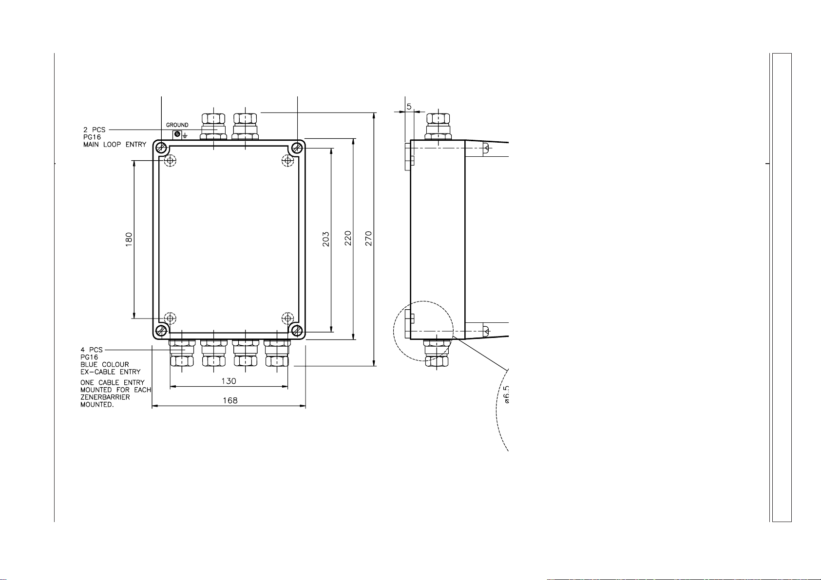
Merk: Festehull for boks til vegg, og lokk til boks er konsentriske.
For å beholde beskyttelsesgrad, IP55.
Note: In order to maintain encapsulation rating, IP55, mounting
holes for box to wall are concentric to the lid's fixing holes.
BZ-056C
SAFE AREA & HAZARDOUS AREA CABLES MUST BE
SEPARATED BY MIN. 50mm INSIDE AND OUTSIDE OF THE
HOUSING.
DIMENTIONAL SKETCH
ZENER BARRIER UNIT TYPE BZ-32/1-4
UNIT MAY BE MOUNTED IN ANY ORIENTATION.

Technical Documentation: Fire Detectors used in hazardous areas
FUNCTIONAL DIAGRAM
ZENER BARRIER UNIT
TYPE BZ-32/1-4
BZ-044C
P-DET/EX/RCE/PM5/GKa/110995 20 Autronica Fire and Security AS

Technical Documentation: Fire Detectors used in hazardous areas
Max 1Ω
CONNECTION DIAGRAM
ZENER BARRIER UNIT
TYPE BZ-32/1
BZ-047A
P-DET/EX/RCE/PM5/GKa/110995 21 Autronica Fire and Security AS
Technical Documentation: Fire Detectors used in hazardous areas
Max 1Ω
CONNECTION DIAGRAM
ZENER BARRIER UNIT
TYPE BZ-32/1-4
P-DET/EX/RCE/PM5/GKa/110995 22 Autronica Fire and Security AS
BZ-049A
Technical Documentation: Fire Detectors used in hazardous areas
MAN. CALL P. BF-32/Ex
(NON INSULATED UNITS)
NON INSULATED UNITS (METAL HOUSING)
SHALL BE CONNECTED TO THE HULL.
MAN. CALL P. BF-35/Ex
(INSULATED UNITS)
INTERFACE UNIT BN-35/Ex
(INSULATED UNITS)
SMOKE DETECTOR BJ-31/Ex
SMOKE DETECTOR BH-31/Ex
HEAT DETECTOR BE-30/Ex
(INSULATED UNITS)
SUB LOOP
HEAT ETECTOR
BD-26/Ex OR
BD-27/Ex
(INSULATED UNITS)
P-DET/EX/RCE/PM5/GKa/110995 23 Autronica Fire and Security AS

Technical Documentation: Fire Detectors used in hazardous areas
Conventional
system type
BX-40
Zener barrier
unit type BZ-20/S
3 Conventional system type BX-40
3.1 Zener barrier unit type BZ-20/S
Barrier unit BZ-20/S is mainly intended to be used together with Autronica
conventional fire alarm systems. The main component is one ac-barrier (see
page 12) for each branch for connection of detectors in hazardous area.
Each unit may contain one or two ac-barriers, and may consequently be loaded
with the same number of loops as the unit contains ac-barriers.
Each loop may take up to ten detectors.
The type indication includes the number of acceptable branches, indicated by a
digit placed behind a diagonal at end of the indication.
E.g. BZ-20/2S means that the maximum number of loops which may be
connected to this unit is 2.
Note!
Units listed below only, may be connected to the zener barrier unit type
BZ-20/nS. (n being the number 1 or 2).
Smoke detector, ion-chamber type BJ-20B/Ex
Heat detector type BE-26M/Ex
Heat detector type BE-27M/Ex
Manual call-point type BF-21M/Ex
Heat detector type BD-26/Ex (BE-26/Ex)
Heat detector type BD-27/Ex (BE-27/Ex)
The detectors may, as described above, be connected to one loop in number of
maximum 10 units.
1)
This is purely estimated from an electro-technical point of view. Other
criterias to be estimated are gas and total capacitance, Ceq.
1)
P-DET/EX/RCE/PM5/GKa/110995 24 Autronica Fire and Security AS

Technical Documentation: Fire Detectors used in hazardous areas
BZ-20/S
Connection
diagram
Arranging
EX-loop
3.2 BZ-20/S, connection diagram, draw. BZ-076 (BZ-078)
The diagram is separated in two main parts by a dot-dash-line. The components
located above that line is mounted in the hazardous area, and must be approved
for the purpose.
At he projecting period it is important to place as little as possible of the total
equipment in the hazardous area.
Note that, of course, all detectors must be approved for mounting inside
hazardous area, i.e. being marked B--/Ex.
Units located below the dot-dash-line are common Autronica fire alarm
equipments. The equipotential line is marked with PE and is connected to
terminal marked 4 on the zener barrier unit.
Note that the equipotential terminal, (marked 4 on the ac-barrier unit) must not
be connected to the system earth inside hazardous area. These two terminals
are, however, shorted inside the ac-barrier unit itself.
Zener barrier unit type BZ-20/1/S contains 1 unit type Z-667/Ex
Zener barrier unit type BZ-20/2/S contains 2 units type Z-667/Ex
3.3 Arranging Ex-loop
One zener barrier for each detector loop in central unit.
If none Ex-detector are mixed with Ex-detectors in the same loop, the Exdetector with it's zener barrier must be the very last element at the loop.
BZ-20/S
Function
description
3.4 BZ-20/S, functional description, drawing BZ-053.
From the diagram containing PCB BZA-20/S, it is seen that the terminals B and
B' are shorted on terminal strip X1.
The resistors R2 have values which make transistor V1 normally non-conducting . The control (base) current for these transistors passes through the detectors (in parallel, also with the end load) via the zener barrier unit.
Monitoring of the loop is obtained by connecting end load BXY-40/Ex to the
last detector.
Fire alarm given by one of the detectors will cause a rise of the transistors base
current. V1 will be conducting, causing a much greater current to flow through
R1. This latter current indicates fire alarm on the central panel.
P-DET/EX/RCE/PM5/GKa/110995 25 Autronica Fire and Security AS
P-DET/EX/RCE/PM5/GKa/110995 26 Autronica Fire and Security AS
SAFE AREA
CONNECTIONS ONLY.
HAZARDOUS AREA
CONNECTIONS ONLY.
Technical Documentation: Fire Detectors used in hazardous areas
BZ-056C
Note: In order to maintain encapsulation rating, IP55, mounting
holes for box to wall are concentric to the lid's fixing holes.
SAFE AREA & HAZARDOUS AREA CABLES MUST BE
SEPARATED BY MIN. 50mm INSIDE AND OUTSIDE OF THE
HOUSING.
DIMENTIONAL SKETCH
ZENER BARRIER UNIT TYPE BZ-32/1-4
UNIT MAY BE MOUNTED IN ANY ORIENTATION.

Technical Documentation: Fire Detectors used in hazardous areas
FUNCTIONAL DIAGRAM
ZENER BARRIER UNIT
TYPE BZ-20/1-2s
BZ-053A
P-DET/EX/RCE/PM5/GKa/110995 27 Autronica Fire and Security AS

Technical Documentation: Fire Detectors used in hazardous areas
1 - 6
Max 1W
CONNECTION DIAGRAM
ZENER BARRIER UNIT
TYPE BZ-20/1S
P-DET/EX/RCE/PM5/GKa/110995 28 Autronica Fire and Security AS
BZ-078
Technical Documentation: Fire Detectors used in hazardous areas
1 - 6
Max 1W
CONNECTION DIAGRAM
ZENER BARRIER UNIT
TYPE BZ-20/2S
BZ-076A
P-DET/EX/RCE/PM5/GKa/110995 29 Autronica Fire and Security AS
Technical Documentation: Fire Detectors used in hazardous areas
MAN CALL P. BF-21M/Ex
(NON INSULATED UNITS)
NON INSULATED UNITS (METAL HOUSING)
SHALL BE CONNECTED TO THE HULL.
HEAT DETECTOR
BD-26/Ex
BD-27/Ex
(INSULATED UNITS)
ZENER BARRIER
UNITS BZ-20/S
.
CONNECTION DIAGRAM FOR FIRE DETECTORS IN
HAZARDOUS AREA (Ex) FOR INSTALLATION IN STEEL
SHIPS. CONVENTIONAL SYSTEM.
A-
B-
P-DET/EX/RCE/PM5/GKa/110995 30 Autronica Fire and Security AS
 Loading...