

Autronica BS-310, BS-320, AutroSafe BS-330, AutroSafe BS-310, AutroSafe BS-320 Operator's Handbook Manual

www.ukpanels.com
Interactive Fire Alarm System
Release 3
System Program Version 3.3.0
Operator's Handbook
Fire Alarm Control Panel, BS-310 / 320 /
Operator Panel BS-330
Protecting life, environment and property...
ASAFE-FO/FE Rev. E, 021105

COPYRIGHT ©
www.ukpanels.com
This publication, or parts thereof, may not
be reproduced in any form, by any
method, for any purpose.
Autronica Fire and Security AS and its
subsidaries assume no reponsibility for
any errors that may appear in the
publication, or for damages arising from
the information in it. No information in this
publication should be regarded as a
warranty made by Autronica Fire and
Security. The information in this
publication may be updated without notice.
Product names mentioned in this
publication may be trademarks. They are
used only for identification.

www.ukpanels.com
Table of Contents
Table of Contents
1. Introduction......................................................................5
1.1 About the Handbook.......................................................................... 5
1.2 The Reader........................................................................................ 5
1.3 Reference Documentation................................................................. 5
1.4 Components ...................................................................................... 6
2. The Operator Panel - Overview.......................................7
2.1 Introduction........................................................................................ 7
2.2 Indication Devices ............................................................................. 8
2.2.1 Upper Section.......................................................................... 8
2.2.2 The Operator Section (lower) .................................................. 9
2.3 The Menu Display.............................................................................. 10
2.4 Operating Buttons.............................................................................. 11
2.4.1 Overview .................................................................................11
2.4.2 Front Push Buttons ................................................................. 12
2.4.3 Alphanumeric Keyboard .......................................................... 12
2.4.4 Utility Buttons ..........................................................................13
2.5 Internal Buzzer................................................................................... 13
3. Operation Mode ...............................................................14
3.1 Introduction........................................................................................ 14
3.2 Conditions in Operation Mode ........................................................... 15
3.3 Alarm Levels...................................................................................... 15
3.4 Access Levels.................................................................................... 15
3.5 How Events are Presented in the Display ......................................... 16
3.6 How to View Points In Alarm ............................................................. 17
3.7 How to View Detailed Zonal Information ........................................... 18
3.8 Action Digits in Operation Mode ........................................................ 19
3.9 Resounding the Internal Buzzer ........................................................ 20
3.10 Resounding Fire Alarm Devices ........................................................ 20
3.11 Resetting the System ........................................................................20
3.12 Alarm Disablement (AlarmDisable) ................................................... 21
3.13 Suppressed Information .................................................................... 21
3.14 Disablement Sources ........................................................................ 21
3.14.1 Overview .................................................................................21
3.14.2 Point Disablements .................................................................22
3.14.3 Other Unit Disablements ......................................................... 22
3.15 Alarm Handling - A Typical Situation ................................................. 23
3.16 Different Types of Detection Zones ................................................... 24
3.16.1 Introduction.............................................................................. 24
3.16.2 Immediate Action Detection Zones ......................................... 24
3.16.3 Coincidence Action Detection Zones ......................................25
3.16.4 Delayed Action Detection Zones ............................................. 26
3.16.5 Delayed Coincidence Detection Zones ................................... 28
3.16.6 Solas Detection Zones ............................................................ 29
Operator's Handbook, AutroSafe Interactive Fire Alarm System, Release 3, ASAFE-FO/FE Rev. E, 021105,
Autronica Fire and Security AS
Page 1

Table of Contents
www.ukpanels.com
4. About «In the Event of….» ..............................................30
5. In the Event of a Fire Alarm ............................................32
5.1 Indications in the Event of a Fire Alarm............................................. 32
5.2 Actions to be Taken in the Event of a Fire Alarm .............................. 33
6. In the Event of a Fire Alarm - with Alarm Delay...........36
6.1 Indications - Fire Alarm with Alarm Delay..........................................36
6.2 Actions to be Taken - Fire Alarm with Alarm Delay...........................37
7. In the Event of a Fire Warning ........................................40
7.1 Indications in the Event of a Fire Warning......................................... 40
7.2 Actions to be Taken in the Event of a Fire Warning.......................... 41
8. In the Event of Faults ......................................................43
8.1 Indications in the Event of Faults....................................................... 43
8.2 Actions to be Taken in the Event of Faults ........................................ 44
9. Menu Mode.......................................................................46
9.1 How to Enter Menu Mode.................................................................. 46
9.2 The Menu Mode Display.................................................................... 46
9.3 Buttons Used to Operate the Menu ................................................... 47
9.4 Action Digits in Menu Mode............................................................... 47
9.4.1 Introduction.............................................................................. 47
9.4.2 Action Digits Table ..................................................................47
9.5 How to Operate in Menu Mode.......................................................... 48
9.6 Example - How to Disable Detection Zones ...................................... 48
9.6.1 Using the Keyboard to Enter Text into the Input Field............. 49
9.6.2 Using the Up/Down Arrows in the Selection Field................... 50
10. Show Status .....................................................................52
10.1 Introduction........................................................................................ 52
10.2 Show Status Menu ............................................................................52
10.3 Show Status - Fire Alarms................................................................. 53
10.4 Show Status – Fire Warnings ............................................................ 54
10.5 Show Status - Faults ......................................................................... 55
10.6 Show Status - Disablements ............................................................. 56
10.7 Show Status - Detection Zones in Test ............................................. 58
10.8 Show Status – Oil & Gas Inhibited Points ......................................... 59
10.9 Show Status – Activated Outputs ...................................................... 60
11. Disabling ..........................................................................62
11.1 General.............................................................................................. 62
11.2 Disable Menu..................................................................................... 62
11.3 Indications on the Operator Panel ..................................................... 63
11.4 Disabling Activated / Deactivated Components................................. 63
11.5 Disabling Detection Zones................................................................. 63
11.6 Disabling Points................................................................................. 64
11.7 Disabling Fire Alarm Devices ............................................................ 64
Operator's Handbook, AutroSafe Interactive Fire Alarm System, Release 3, ASAFE-FO/FE Rev. E, 021105,
Autronica Fire and Security AS
Page 2

Table of Contents
www.ukpanels.com
11.8 Disabling Fire Alarm Routing Equipment ..........................................64
11.9 Disabling Outputs .............................................................................. 64
11.10 Disabling Fault Warning Routing Equipment..................................... 65
11.11 Disabling Immediate Output Actioning .............................................. 65
11.12 How to Execute Commands from the Disable Menu ....................... 66
12. Enabling ..........................................................................68
12.1 General.............................................................................................. 68
12.2 Enable Menu ..................................................................................... 68
12.3 Enabling Activated / Deactivated Components ................................. 69
12.4 Enabling Detection Zones ................................................................. 69
12.5 Enabling Points.................................................................................. 69
12.6 Enabling Fire Alarm Devices ............................................................. 69
12.7 Enabling Fire Alarm Routing Equipment ........................................... 70
12.8 Enabling Outputs ............................................................................... 70
12.9 Enabling Fault Warning Routing Equipment .....................................70
12.10 Enabling Immediate Output Actioning ...............................................70
12.11 How to Execute Commands from the Enable Menu ......................... 71
13. System Menu....................................................................73
13.1 Introduction........................................................................................ 73
13.2 System Menu..................................................................................... 73
13.3 How to Set / Change Date and Time................................................. 74
13.4 How to View Current Program Version.............................................. 75
13.5 How to Enter Access Level 3 / Set Password ................................... 76
13.5.1 Introduction.............................................................................. 76
13.5.2 Enter Access Level 3 .............................................................. 77
13.5.3 Leave Access Level 3 .............................................................77
13.5.4 Set (or Change) Password ...................................................... 78
13.6 How to Feed Paper............................................................................ 79
13.7 How to Change Language................................................................. 80
13.8 How to Initialize the Fire Alarm System............................................. 81
13.9 Day / Night Timers............................................................................. 82
13.9.1 Starting / Stopping Automatic Day / Night
Operation from the Control Panel ........................................... 82
13.9.2 Overriding Automatic Day / Night Operation from the
Control Panel........................................................................... 83
14. Service Commands .........................................................84
14.1 Introduction........................................................................................ 84
14.2 Service Menu..................................................................................... 84
14.3 Testing............................................................................................... 85
14.3.1 Testing Detection Zones .........................................................86
14.3.2 Testing Outputs ....................................................................... 91
14.3.3 Output Control......................................................................... 99
14.4 Event Recording – Log Menu ............................................................ 101
14.4.1 Events .....................................................................................102
14.4.2 How to Use the Log Menu....................................................... 103
14.4.3 Logging All Events................................................................... 105
14.4.4 The Log Setup Menu............................................................... 106
14.5 Loop Commands ............................................................................... 111
14.5.1 Clear Topology ........................................................................ 111
14.5.2 Disable Loop ...........................................................................113
Operator's Handbook, AutroSafe Interactive Fire Alarm System, Release 3, ASAFE-FO/FE Rev. E, 021105,
Autronica Fire and Security AS
Page 3

Table of Contents
www.ukpanels.com
14.5.3 Enable Loop ............................................................................ 114
14.6 Oil & Gas Inhibit................................................................................. 115
14.6.1 Inhibit Point.............................................................................. 115
14.6.2 Cancel Inhibit Point .................................................................117
15. Appendix ..........................................................................119
15.1 Terms and Abbreviations .................................................................. 119
15.2 Zonal Definitions................................................................................ 121
15.2.1 General.................................................................................... 121
15.2.2 Detection Zone........................................................................ 121
15.2.3 Alarm Zone.............................................................................. 122
15.2.4 Operation Zone .......................................................................122
15.2.5 Configuration Example ............................................................ 123
15.3 Action Digits Table - Operation Mode................................................ 124
15.4 Menu Structure .................................................................................. 126
16. Index ..........................................................................127
17. Figure List ........................................................................128
18. Reader’s Comments........................................................129
Operator's Handbook, AutroSafe Interactive Fire Alarm System, Release 3, ASAFE-FO/FE Rev. E, 021105,
Autronica Fire and Security AS
Page 4

1. Introduction
www.ukpanels.com
1.1 About the Handbook
This handbook is intended to provide the information necessary to
operate the AutroSafe Interactive Fire Alarm System from the Fire
Alarm Control Panel, BS-310/320 or the Operator Panel, BS-330.
As the user interface and operation of both panels are identical, the
panel is referred to as the operator panel throughout this handbook.
1.2 The Reader
The handbook is intended to be used by personnel who are
responsible for operating the system. W e assume the reader has the
necessary basic understanding of the system concept (refer to System
Specification), and the term zone including, Detection Zone, Alarm
Zone and Operation Zone (refer to Appendix).
The AutroSafe Interactive Fire Alarm System comprises various
components (see chapter 1.4). It is important that the reader gets
familiarized with these, plus the different terms and abbreviations. A
list containing the most commonly used terms and abbreviations is
included in Appendix.
Introduction
1.3 Reference Documentation
In addition to this handbook, Autronica Fire and Security offers the
following handbooks:
Handbook Item Number
System Specification P-ASAFE/XE
Installation Handbook, Fire Alarm Control Panel (BS-310/320) / Controller (BC-320) P-ASAFE-FA/DE
Installation Handbook, Operator Panel (BS-330) P-ASAFE-OP/DE
Installation Handbook, Repeater Panel (BU-320) / Information Panel (BV-320) P-ASAFE-RI/DE
Installation Handbook, Battery Cabinet (SY-310) P-ASAFE-BC/DE
Commissioning Handbook P-ASAFE/EE
Operator's Handbook, Repeater Panel (BU-320) P-ASAFE-FB/FE
Operator's Handbook, Information Panel (BV-320) P-ASAFE-IN/FE
Shortform User Guide P-ASAFE-SH/LE
Shortform Configuration Guide (for the AutroSafe Demo Board) P-ASAFE-SH/VE
Wall Chart P-ASAFE-WE/LX
Wall Chart P-ASAFE-CH/LX
Menu Structure P-ASAFE/MX
User Guide, Loop Diagnostic Tool, AS-2000 P-ASAFE-AS/FE
User Guide, Loop Simulator Tool P-ASAFE-LS/FE
User Guide, Loop Calculator Tool P-ASAFE-LC/FE
User Guide, Merge Tool P-ASAFE-MT/FE
User Guide, Power Calculator Sheet P-ASAFE-PC/FE
Operator's Handbook, AutroSafe Interactive Fire Alarm System, Release 3, ASAFE-FO/FE Rev. E, 021105,
Autronica Fire and Security AS
Page 5

Introduction
www.ukpanels.com
1.4 Components
The AutroSafe Interactive Fire Alarm System comprises the following
components (EN-54) :
Component Abbreviation Description Ref.
Point - Detector or manual call-point.
Control and indicating
equipment
c.i.e. Equipment supplying power to, as well as
accepting fault and alarm signals from detectors.
Indicates an alarm condition audibly and visibly,
plus the location.
Power Supply - The source of power for control and indicating
equipment and for items supplied with power from
such equipment.
Fire Alarm Devices FAD Equipment used to give warning of fire, for
example, a sounder or visual indicator.
Fire Alarm Routing
Equipment
FARE Equipment used to route an alarm signal from
control and indicating equipment to a Fire Alarm
Receiving Station.
Control for Fire
Protection Equipment
FPE An automatic device used to actuate measures of
fire protection after receiving a signal from control
and indicating equipment (for example, fire
extinguishers, ventilation controllers).
Fault Warning Routing
Equipment
FWRE Equipment used to route a fault warning signal
from control and indicating equipment to a fault
warning receiving station.
Fire Alarm Receiving
Station
Fault Warning Receiving
Station
Automatic Fire Protection
Equipment
- A centre from which the necessary fire protection
measures can be initiated at any time.
- A centre from which the necessary corrective
measures can be initiated.
- Fire control or fire fighting equipment, for example,
extinguishing installation.
C
C
Fire Alarm
Device
E
Fire Alarm
Routing Eq.
J
Fault Warning
Routing Eq.
G
Control for
Automatic
Fire Protection Eq.
A
D
Fire
A
detectors
Points
Manual
D
call-points
B
Control
and
indicating
equipment
F
K
H
A /
D
B
L
C
E
G
J
F
K
H
Fire Receiving
Station
Fault Warning
Receiving
Station
Automatic Fire
Protection Eq.
L
Power
Supply
Note:
The lines linking the various components on the illustration indicate information flows,
and not physical interconnections.
Item G and H and some other items may need to be provided with a seperate power supply.
Operator's Handbook, AutroSafe Interactive Fire Alarm System, Release 3, ASAFE-FO/FE Rev. E, 021105,
Autronica Fire and Security AS
Page 6

The Operator Panel - Overview
www.ukpanels.com
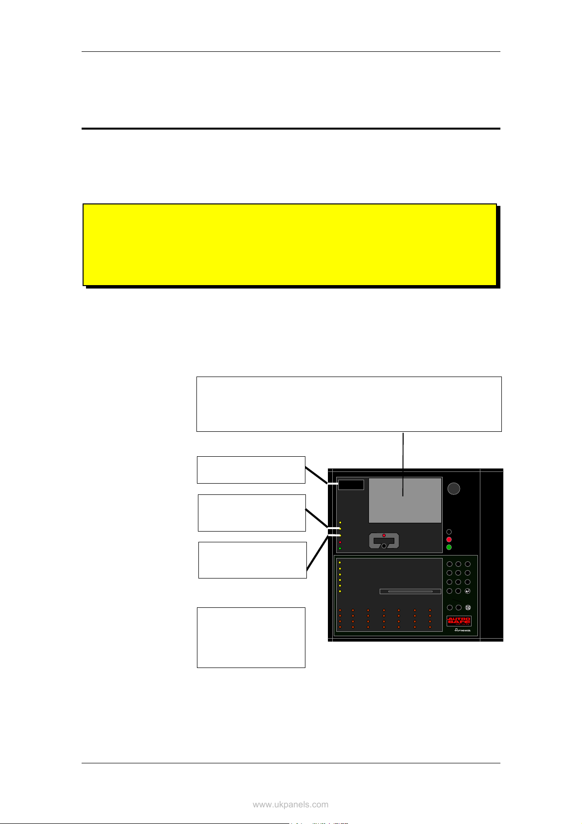
2. The Operator Panel - Overview
2.1 Introduction
Each operator panel is assigned to one Operation Zone (refer to
«Zonal Definitions» in Appendix). Relative to its own zone, an operator
panel is local, while it is remote to operation zones which are not
encompassed by the local zone. All events and actions occurring in a
particular operation zone must be handled from a local operator panel.
The operator panel displays information on events occurring in all
operation zones. However, the type of events and the level of details of
the given information depends on which operation zone the
information is related to. Local panels will list all detection zones in fire
alarm state. Remote operator panels will list remote alarms only, and
function as «indication only» devices.
The operator panel consists of two main sections. The upper section,
and the lower section which is the Operator Part.
ALARM
Fault
Function Disabled
Function Delayed
Fire Brig. Signalled
Power
Testing
Fire Brig. Disabled
Fire Brig. Fault
System Fault
Alarms Disabl ed
Alarms Fault
Figure 2-1: The Operator Panel
More Events
AUTROSAFE
SelfVerify
19:23
Mute Panel
Silence Alarms
Reset
2
1
4
7
C
i
3
5
6
98
0
!!!!
Operator's Handbook, AutroSafe Interactive Fire Alarm System, Release 3, ASAFE-FO/FE Rev. E, 021105,
Autronica Fire and Security AS
Page 7

The Operator Panel - Overview
www.ukpanels.com
2.2 Indication Devices
2.2.1 Upper Section
ALARM
The red alarm indicator shows that one or more
detection zones within the operating zone of the
Operator Panel are in the fire alarm state.
•
Blinking red light:
In the event of a fire alarm. The Fire Alarm
Devices (FAD) are still in active state.
•
Steady red light:
All FADs activated by the fire alarm condition
have been deactivated by operating the Silence
Alarms button. The control and indicating
equipment still remain in the fire alarm condition.
The yellow Fault Warning indicator shows the
presence of a fault within the operation zone of
the operator panel.
•
•
Steady yellow light when one or more of the
following components within the operation zone
of the operator panel are in the disabled state:
•
•
•
•
•
Steady yellow light indicates that Immediate Output
Actioning has been disabled (manual operation in
Menu Mode), i.e. a delay period is active for Fire
Alarm Devices (FAD) or Fire Alarm Routing
Equipment (FARE). Configurable.
Steady red light when the message is sent to the
Fire Brigade.
Fault
Blinking light
Unaccepted fault warnings exist.
Steady light
All fault warnings are accepted.
Function Disabled
function delayed
individual points
detection zones
alarm zones
Fire Alarm Devices, Fire Alarm Routing
Equipment, Fire Protection Equipment and
Fault Warning Routing Equipment.
Function Delayed
Fire Brig. Signalled
Power
Steady green light when power is ON.
Operator's Handbook, AutroSafe Interactive Fire Alarm System, Release 3, ASAFE-FO/FE Rev. E, 021105,
Autronica Fire and Security AS
Page 8
Text Display -
ALARM
ALARM
ALARMALARM
Fault
Function D isabled
Function De layed
Fire Brig. Signalled
Power
More Events
In the event of more than one alarm.
The red More Events indicator shows that several
detection zones within an operating zone are in
the fire alarm state.
•
•
More Events
Blinking red light:
In the event of a fire alarm. The Fire Alarm
Devices (FAD) are still in active state.
Steady red light:
The Silence Alarms button has been pressed.
All
FADs activated by the fire alarm are no longer
active. The control and indicating equipment
still remain in the fire alarm condition.
See chapter 2.3.
Silence Alarms
Mute Panel
Reset Syste m
Note that there are several
national variants of this panel.
The Indication Devices shown in
this handbook deals with
the Indication Devices for the
standard panel.

The Operator Panel - Overview
www.ukpanels.com
2.2.2 The Operator Section (lower)
Testing
Steady yellow light when one or more detection zones within the operation zone of the operator
panel have been manually set to the test state.
Fire Brig. Disabled
Steady yellow light when the signal to Fire Alarm Routing Equipment (FARE)
has been disabled. The Function Disabled indicator has also a steady yellow light.
Fire Brig. Fault
Yellow light when a fault is detected on Fire Alarm Routing Equipment (FARE). The Fault indicator
will also have a yellow light. Blinking (not accepted) / Steady (accepted).
System Fault
Steady yellow light when a system fault within the operating zone of the operator panel is present.
Alarms Disabled
Steady yellow light when one or more Fire Alarm Devices are disabled. The Function Disabled
indicator has also a steady yellow light.
Alarms Fault
Yellow light when a fault is detected on one or more Fire Alarm Devices (FAD). The Fault indicator
will also have a yellow light. Blinking (not accepted) / Steady (accepted).
Testing
Fire Brig. Disabled
Fire Brig. Fault
System Fault
Alarms Disabled
Alarms Fault
21
3
4
5
6
98
7
0
C
!!!!
i
Operator's Handbook, AutroSafe Interactive Fire Alarm System, Release 3, ASAFE-FO/FE Rev. E, 021105,
Autronica Fire and Security AS
Page 9

The Operator Panel - Overview
www.ukpanels.com
2.3 The Menu Display
During Normal Operation, the back light in the menu display is always
on.
The menu display has 16 lines of 40 characters.
The display is divided into several display windows showing different
types of information.
SHOW STATUS
SHOW STATUS
DISABLEMENTS
DISABLEMENTS
1 DETECTION ZONES
1 DETECTION ZONES
2 POINTS
2 POINTS
3 FIRE ALARM DEVICES
3 FIRE ALARM DEVICES
4 FIRE ALARM ROUTING EQUIPMENT
4 FIRE ALARM ROUTING EQUIPMENT
5 OUTPUTS
5 OUTPUTS
6 FAULT WARNING ROUTING EQUIPMENT
6 FAULT WARNING ROUTING EQUIPMENT
7 IMMEDIATE OUTPUT ACTIONING
7 IMMEDIATE OUTPUT ACTIONING
8 ALL
8 ALL
FIRE ALARM
FIRE ALARM
5 CONFERENCE HALL, MAIN BUILDING
5 CONFERENCE HALL, MAIN BUILDING
Figure 2-2: The Menu Display
19.23
19.23
Header
HeaderHeader
Time
TimeTime
Menu path
Menu path
Menu path
information
information
information
Menu elements
Menu elementsMenu elements
Information
Information
Information
field
field
field
Last alarm
Last alarm
Last alarm
detected if in
detected if in
detected if in
alarm condition
alarm condition
alarm condition
Operator's Handbook, AutroSafe Interactive Fire Alarm System, Release 3, ASAFE-FO/FE Rev. E, 021105,
Autronica Fire and Security AS
Page 10

2.4 Operating Buttons
www.ukpanels.com
2.4.1 Overview
19:23
Mute Panel
Silence Alarm s
Reset
21
4
5
7
0
C
!!!!
i
ALARM
Fault
Function Disabled
Function Delayed
Fire Brig. Signalled
Power
Testing
Fire Brig. Disabled
Fire Brig. Fault
System Fault
Alarms Disabled
Alarms Fault
AUTROSAFE
More Events
SelfVerify
The Operator Panel - Overview
Front Push Buttons
Mute Panel
(black)
Silence Alarms
(red)
3
6
98
Reset
(green)
Alphanumeric Keyboard
1
ABC
2
DEF
3
GHI
More Events
v
Figure 2-3: Operating Buttons
v
More Events
(black)
4
JKL
7
STU
C
5
MNO
8
VWX
0
6
PQR
9
YZ
Utility Buttons
!
i
Help Menu Close
Operator's Handbook, AutroSafe Interactive Fire Alarm System, Release 3, ASAFE-FO/FE Rev. E, 021105,
Autronica Fire and Security AS
Page 11

The Operator Panel - Overview
www.ukpanels.com
2.4.2 Front Push Buttons
Button Designation Access
Mute Panel
v
v
(black)
Silence Alarms
(red)
Reset
(green)
More Events
(black)
Front Push Buttons
Level
Used to mute the panel. Timeout. 1
Used to silence Fire Alarm Devices (FAD) and cause
blinking serial numbers and lamps to go steady.
Timeout.
Used to reset the system.
In addition, a lamp test can be performed by pressing
and holding the Reset button for at least 5 seconds.
The lamp test is performed in access level 1 (no use
of key).
Used to scroll downwards among events in currently
active window (scroll page by page). Possible only if
there are more alarms than possible to display in the
window.
2
2
2
2.4.3 Alphanumeric Keyboard
The alphanumeric keyboard includes the numbers 1 to 9, the letters A
to Z, plus the following buttons:
Alphanumeric Keyboard
Button Designation
ENTER Used to select/approve a selection (parameter) or return.
6
PQR
9
YZ
Up/down arrow
buttons
Cancel Used to cancel the last alphameric character input (back space).
Used to scroll lines up and down in the display picture.
C
Operator's Handbook, AutroSafe Interactive Fire Alarm System, Release 3, ASAFE-FO/FE Rev. E, 021105,
Autronica Fire and Security AS
Page 12

2.4.4 Utility Buttons
www.ukpanels.com
Button Designation
Help The Help button allows you to get useful information quickly while
i
Menu Used to switch between Operation Mode and Menu Mode.
!
Close Used to move back one level / show previous picture if the display is
2.5 Internal Buzzer
The Operator Panel - Overview
Utility Buttons
operating the system. You can look up information on how to
operate the panel. NOT YET IMPLEMENTED.
Operation Mode (operate !) >> Menu Mode (operate ! or timeout) >> Operation Mode.
not showing information on the top level.
Each operator panel provides a buzzer which is activated as described
below. Each condition may have its own sound pattern. If more than
one condition is present simultaneously, the state of the operator panel
and the buzzer signal will be decided. The buzzer will reflect the
condition which has the highest priority.
The internal buzzer is controlled by hardware. It is activated in the
cases of:
• System Fault
• Alarm
• Prealarm
• Fault
• Early Warning (not yet implemented)
The buzzer can be silenced by pressing the Mute Panel button. One
exception is the buzzer signal indicating System Fault which can not
be silenced.
If the reason for the buzzer signal still exists, the buzzer will resound
after a predefined time.
Operator's Handbook, AutroSafe Interactive Fire Alarm System, Release 3, ASAFE-FO/FE Rev. E, 021105,
Autronica Fire and Security AS
Page 13

Operation Mode
www.ukpanels.com
3. Operation Mode
3.1 Introduction
The operator panel can be in either Operation Mode or Menu Mode.
When no one is operating the panel and no button has been pressed,
the panel will always be in Operation Mode.
The display may look as follows in the panel’s idle state.
AUTROSAFE
SelfVerify
19:23
Total: 3
Figure 3-1: The idle display
Note that an alarm, a disablement, test or fault will always be indicated
on the display when such events occur.
NOTE:
All events that may occur are presented in Operation Mode.
All handling of events, i.e. Silence Alarms, Accept and
System Reset takes place in Operation Mode.
It is possible to enter Operation Mode in two different ways.
• initial mode (start up) - idle state
• when pressing the menu button in Menu Mode, which will leave
menu mode from all menu levels
Operator's Handbook, AutroSafe Interactive Fire Alarm System, Release 3, ASAFE-FO/FE Rev. E, 021105,
Autronica Fire and Security AS
Page 14

3.2 Conditions in Operation Mode
www.ukpanels.com
In Operation Mode, the system can be in quiescent condition (lowest
priority), or the system can be in one or any combination of the
following conditions:
• fire alarm condition (highest priority)
• fire warning condition (including prealarm)
• fault warning condition
• disablement condition
• test condition
3.3 Alarm Levels
A detector may signal different levels of alarm, indicating the amount
of smoke or gas currently present. These are;
• Fire Alarm Level (the highest level)
• Fire Warning, including:
- Prealarm Level
- Early Warning
Whenever a detector detects a transition from one alarm level to
another, this event is reported to the system as an Early Warning,
Prealarm or Fire Alarm signal, which in turn will initiate the appropriate
actions.
Operation Mode
3.4 Access Levels
All user interface controls are classified as belonging to one of the four
different access levels described below:
Access
Level
1 No key or password
2 Access by key.
3 Password restricted. Accessible by persons trained and authorized to do
4 Mechanical tool. Accessible by persons doing repair work and changing
Access Remedy Description
required.
Accessible by members of the general public. All mandatory
indications are visible at access level 1 without prior manual
intervention.
Accessible by persons having a specified responsibility for
safety.
reconfiguration of site specific data and maintenance
according to the manufacturer’s published instruction.
firmware.
Operator's Handbook, AutroSafe Interactive Fire Alarm System, Release 3, ASAFE-FO/FE Rev. E, 021105,
Autronica Fire and Security AS
Page 15

Operation Mode
www.ukpanels.com
3.5 How Events are Presented in the Display
The different events, for example, «In the Event of a Fire Alarm», are
presented in Operation Mode. FIRE ALARMS, for example, is shown
highlighted in the upper left corner of the display.
The example below shows a situation where three zones are in alarm
state. The total number of zones in alarm is shown in the upper right
corner.
Total number
Zones in alarm
of zones in alarm
FIRE ALARMS
1 OFFICES
2 CANTEEN
3 WORKSHOP
Figure 3-2: How events are presented
19:23
Total: 3
Operator's Handbook, AutroSafe Interactive Fire Alarm System, Release 3, ASAFE-FO/FE Rev. E, 021105,
Autronica Fire and Security AS
Page 16

3.6 How to View Points In Alarm
www.ukpanels.com
To be able to select among detection zones in alarm, for example, «In
the Event of a Fire Alarm», you simply press the ENTER button
You can now use the up/down arrow buttons to select the wanted
zone.
FIRE ALARMS
1 OFFICES
2 CANTEEN
3 WORKSHOP
1: SHOW POINTS
To view points in alarm for the zone you have selected (highlighted),
you simply press digit 1 (SHOW POINTS, see Action Digits, 3.8), and
the following screen picture will appear (example):
The exact time
when the alarm
was received
19:23
19:23
Total: 3
Total: 3
Operation Mode
( ).
The point(s)
in alarm
SHOW STATUS
FIRE ALAR MS/POINTS
1 OFFICES
Received 19:29:44
POINT: TYPE: STATUS:
P3 Heat Alarm
P5 Optical Alarm
FIRE ALARMS Total: 3
3 WORKSHOP
Last zone
in alarm
Figure 3-3: Points in Alam
The point
type
19:23
Total: 3
Total number
of zones in alarm
Here (in this example) you can view the points in alarm and the type of
point (detector type, manual call point). The arrow buttons are used to
move up and down in the list of points.
The close button ( ) is used to go one step backwards (at any time).
NOTE: If you have entered SHOW STATUS for information on points in alarm, you have
to press the Close button to re-enter Operation Mode in order to activate the Silence
Alarms button and the Reset button.
Operator's Handbook, AutroSafe Interactive Fire Alarm System, Release 3, ASAFE-FO/FE Rev. E, 021105,
Autronica Fire and Security AS
Page 17

Operation Mode
www.ukpanels.com
3.7 How to View Detailed Zonal Information
To be able to select among zones in alarm, fault or test state, you
simply press the ENTER button ( ). You can now use the up/down
arrow buttons to select the wanted zone (in this example Fire Alarms).
19:23
FIRE ALARMS
1 OFFICES
2 CANTEEN
3 WORKSHOP
1: SHOW POINTS
To view detailed zonal information for the zone you have selected
(highlighted), you simply press the ENTER button ( ) once more. ,
The following screen picture will appear (example):
Zone in
Alarm
First
point
The point
type
FIRE ALARM INFO
ZONE IN ALARM
OFFICES
FIRST POINT/MCP IN FIRE ALARM:
P6 Manual
TIME ENTERING ALARM: 19:07
OUTPUTS : Activated
ACTIVATED BY : McpOperation
ACTIVATION TIME : 19:07
1: SHOW POINTS
FIRE ALARMS Total: 3
3 WORKSHOP
19:23
Total: 3
Total: 3
The time
entering
alarm
Outputs
activated
(or not)
19:23
Total: 3
Last
zone
in alarm
Figure 3-4: Detailed Zonal Information - Example: Fire Alarm Info
Activated
by
The
activation
time
Total
number
of zones
in alarm
Detailed zonal information will be available. In the example above you
can view the zone in alarm, the first point in fire alarm, the time
entering alarm, the activation state of outputs, what triggered the alarm
(for example, Manual Call-point operation) and the activation time. You
can also move directly to SHOW POINTS (press digit 1).
The close button ( ) is used to go one step backwards (at any time).
NOTE: If you have entered SHOW STATUS for more detailed point information, you have
to press the Close button to re-enter Operation Mode in order to activate the Silence
Alarms button and the Reset button.
Operator's Handbook, AutroSafe Interactive Fire Alarm System, Release 3, ASAFE-FO/FE Rev. E, 021105,
Autronica Fire and Security AS
Page 18

3.8 Action Digits in Operation Mode
www.ukpanels.com
When operating in Operation Mode, special Action Digits will appear in
the highlighted field (Information Field) at the lower part of the display.
These digits show at any time which action the operator may perform.
Digits 1 to 4 on the alphanumeric keyboard are dedicated for
the different actions (Action Digits). The type of action
depends on the current state of the system.
Operation Mode
1
ABC
2
DEF
3
GHI
4
JKL
Figure 3-5: Action Digits in Operation Mode
For example, digit 1 in the event of a fire alarm (after silencing alarms)
represents RESOUND.
The example below shows a situation where Action Digit 4 (SHOW
SUPPR. INFO = suppressed information) is available.
FIRE ALARMS
1 OFFICES
2 WORKSHOP
3 CANTEEN
19:23
Total: 3
4: SHOW SUPPR. INFO
Action Digit
Figure 3-6: Action Digits shown in the Information Field
In Appendix you will find a table providing a complete list of all Action
Digits that may appear in Operation Mode.
Operator's Handbook, AutroSafe Interactive Fire Alarm System, Release 3, ASAFE-FO/FE Rev. E, 021105,
Autronica Fire and Security AS
Page 19

Operation Mode
www.ukpanels.com
3.9 Resounding the Internal Buzzer
After pressing the MUTE PANEL button in an alarm condition, the
internal buzzer will automatically be resounded in the following cases:
• if any new event occurs (for example, a detection zone enters the
Fire Alarm state)
• after a timeout period if the cause for making it sound is still
present.
3.10 Resounding Fire Alarm Devices
When pressing the SILENCE ALARMS button in the event of an
alarm, all fire alarm devices (FAD) within the operation zone of the
operator panel will be deactivated. The red Fire Alarm indication lamp
will switch from blinking to steady light.
At this stage, the resound timer will start. The resound timer will restart
on each operation of the SILENCE ALARMS button.
To manually resound the alarm zones, Action Digit 1, which represents
RESOUND, can be pressed.
The alarm zones are automatically resounded to their alarm states on
timeout (configurable) of the SILENCE resound timer.
3.11 Resetting the System
In order to reset the system by pressing the RESET button, all Fire
Alarm Devices (FAD) have to be silenced / deactivated using the
SILENCE ALARMS button. Otherwise the reset operation will be
rejected without having any effect on system behaviour.
Operator's Handbook, AutroSafe Interactive Fire Alarm System, Release 3, ASAFE-FO/FE Rev. E, 021105,
Autronica Fire and Security AS
Page 20

3.12 Alarm Disablement (AlarmDisable)
www.ukpanels.com
If there are points within an operation zone still signalling a Fire Alarm,
an alarm disablement will take effect.
Alarmdisabling may or may not be required to be confirmed by the
operator (configurable).
• If confirmation is not required, all points still signalling a Fire Alarm,
are automatically disabled.
• If confirmation is required, a list of points in alarm is presented on
the display. To confirm automatic disablement, the ENTER button
( ) must be pressed within 5 seconds (configurable).
All alarmdisabled detectors can be enabled at this stage by pressing
Action Digit 3, which represents REACTIVATE .
3.13 Suppressed Information
When operating in Operation Mode, the message SHOW SUPPR.
INFO may appear in the highlighted field at the lower part of the
display. This indicates that there are conditions that are active, but
suppressed, i.e. not shown on the display.
To reveal suppressed information, Action Digit 4, representing SHOW
SUPPRESSED INFO, can be pressed.
Operation Mode
3.14 Disablement Sources
3.14.1 Overview
The AutroSafe Interactive Fire Alarm System supports the following
disablement sources:
• Individual
A unit is disabled by an individual command issued to the specified
unit. Applicable to all units with disable capability.
• Loop
A unit is dsabled by its corresponding loop being disabled.
Applicable to Points, FADs, FPEs and panels connected to loops
(DID, remote silence / reset).
• Zone
A point is disabled by a command to its corresponding detection
zone, affecting all Points in the detection zone, including any
manual call points. Applicable to Points only.
• Disable Input Unit
A point is disabled by a command from a Disablement Input Unit
via its corresponding detection zone. Applicable to Points only.
• Master Zone
equivalent with Zone, except from that the command is issued to
AutroSafe over the AutroCom connection. Applicable to Points only.
Operator's Handbook, AutroSafe Interactive Fire Alarm System, Release 3, ASAFE-FO/FE Rev. E, 021105,
Autronica Fire and Security AS
Page 21

Operation Mode
www.ukpanels.com
3.14.2 Point Disablements
A general rule is that a Point may be disabled by one or more
disablement sources simultaneously. To be enabled, the Point must
be enabled from all these disablement sources.
Example:
A Point is disabled from a Zone (Detection Zone disable command
issued from an Operator Panel) and from a Disable Input Unit. For the
Point to become enabled, a DZ enable command must be issued from
the Operator Panel and the Restore button on the Disable Input Unit
must be pressed.
Exceptions to this general rule is as follows:
• Individual enablements will override and remove all other
disablements but Loop disablements. The reason for this is that an
individual Point disablement should be regarded as a sort of
service command used in exceptional circumstances, disabling of
Points is usually done via its Detection Zone.
• Master Zone enablements will override and remove all Master
Zone, Zone and Disablement Input Unit disablements.
3.14.3 Other Unit Disablements
Other units (than Points) are only affected by Individual and Loop
disablements.
Note that in contrast to Point disablements, there is no memory in the
system in conjunction with Loop disable / enable operations: When a
loop is disabled and then enabled, any disablements which may have
existed before the loop disable will be lost. In other words, all loop
units (except Points which have this memory function, see above) will
be enabled when enabling the corresponding loop.
Operator's Handbook, AutroSafe Interactive Fire Alarm System, Release 3, ASAFE-FO/FE Rev. E, 021105,
Autronica Fire and Security AS
Page 22

3.15 Alarm Handling - A Typical Situation
www.ukpanels.com
The handling of a fire situation will typically contain the following
phases:
• One or more detection zones are issuing Prealarm signals
(Accept).
• One or more of these detection zones will go into Fire Alarm,
activating Fire Alarm Devices (FAD) and Fire Protection Equipment
(FPE).
• When the operator has investigated the cause of the alarm, the
activated Fire Alarm Devices (FAD) may be deactivated when the
situation is under control (Silence Alarms).
• If the deactivation of the Fire Alarm Devices (FAD) shows to be
erroneous, the Fire Alarm Devices (FAD) may be resounded
(Resound).
• After silencing the Fire Alarm Devices (FAD), the system may be
reset. Reset will delete all indications of the fire situation and, if
physically possible, deactivate the Fire Protection Equipment
(FPE) (Reset).
Operation Mode
• The reset operation includes alarm disabling of all those points
within the operation zone of the operating panel still signalling Fire
Alarm (must be confirmed by the operator). Alarmdisabling may
later be cancelled and the points made to retransmit their alarm
level (Reactivate).
Operator's Handbook, AutroSafe Interactive Fire Alarm System, Release 3, ASAFE-FO/FE Rev. E, 021105,
Autronica Fire and Security AS
Page 23

Operation Mode
www.ukpanels.com
3.16 Different Types of Detection Zones
3.16.1 Introduction
When handling events in Operation Mode, it is important to be aware
of differences regarding the detection zone configuration (configured
by using the AutroSafe Configuration Tool).
The type of the specific detection zone as well as the type of point
(detector or manual call point) will determine how the system responds
to the signal - with respect to action.
The system has the following types of detection zones:
• Immediate Action detection zone
• Coincidence Action detection zone
• Delayed Action detection zone
• Delayed Coincidence detection zone
• SOLAS (Safety of Life at Sea) detection zone
3.16.2 Immediate Action Detection Zones
A signal from an Immediate Action detection zone, will initiate all
actions immediately, without any delay.
Immediate Action applies to:
• Fire Alarm Devices (FAD)
• Fire Alarm Routing Equipment (FARE)
• Fire Protection Equipment (FPE)
Operator's Handbook, AutroSafe Interactive Fire Alarm System, Release 3, ASAFE-FO/FE Rev. E, 021105,
Autronica Fire and Security AS
Page 24

3.16.3 Coincidence Action Detection Zones
www.ukpanels.com
A fire alarm signal from a single detector in a Coincidence Action
detection zone, will initiate no actions, i.e. there will be no actioning of
outputs to;
• Fire Alarm Devices (FAD)
• Fire Alarm Routing Equipment (FARE)
• Fire Protection Equipment (FPE)
-
provided that FAD, FARE and FPE are set to Qualified Action (see
next page)
At least two detectors in the same detection zone must be in
alarm state before actions are initiated.
Note that an activation of a manual call-point in a coincidence
action detection zone will always initiate actions.
In the display, the alarm number for a detection zone will remain
steady until a new point in the same zone enters alarm state.
In the example below, the detection zone 2 CANTEEN is configured as
a zone with coincidence action.
Steady number (2) if only one detector
in this zone is in alarm state.
Operation Mode
FIRE ALARMS
1 OFFICES
2 CANTEEN
3 WORKSHOP
Blinking number (2) if two or several
points or one manual call point in the
same zone are in alarm state.
FIRE ALARMS
1 OFFICES
2 CANTEEN
3 WORKSHOP
19:23
Total: 3
19:23
Total: 3
Figure 3-7: Coincidence Action detection zone - indication
Operator's Handbook, AutroSafe Interactive Fire Alarm System, Release 3, ASAFE-FO/FE Rev. E, 021105,
Autronica Fire and Security AS
Page 25

Operation Mode
www.ukpanels.com
3.16.4
Delayed Action Detection Zones
When the operator panel receives a fire alarm signal from a point in a
Delayed Action detection zone (configurable), the actioning of outputs
to Fire Alarm Devices (FAD) and/or Fire Alarm Routing Equipment
(FARE) can be delayed.
In an alarm situation, the actioning of outputs will be delayed when;
• the detection zone has been defined as a Delayed Action detection
zone (configurable)
• the point(s) in this Delayed Action detection zone has been set to
point delay ON (the default configuration)
• Immediate Output Actioning has been disabled (in the Disable
menu, refer to How to Disable Immediate Output Actioning, page
65).
• the actual FAD / FARE has been set to Qualified Action
(configurable)
Note that activation of a manual call-point will normally (point
delay OFF) give immediate output actioning even though the
immediate output actioning has been disabled (configurable).
The operation of delays to outputs to Fire Alarm Devices (FAD) and
Fire Alarm Routing Equipment apply to:
• detectors and/or
• manual call-points and/or
• signals from specific zones
The delay is divided into two delay periods, Initial delay, T1
(configurable) and Prolonged Delay, T2 (configurable).
The (T1) delay period is started when a Fire Alarm signal from a point
is received. Actions will be initiated after the T1 delay period has
expired. Pressing Action Digit 4, which represents PROLONG DELAY,
will terminate T1 and the delay period T2 will start.
If one or more Delayed Action detection zones have entered the Fire
Alarm state and are in their T1 or T2 periods, the delayed actions can
be immediately initiated by pressing Action digit 2, which represents
ACTIVATE. Activation of a manual call point with the Operation Zone
will also give immediate action.
Operator's Handbook, AutroSafe Interactive Fire Alarm System, Release 3, ASAFE-FO/FE Rev. E, 021105,
Autronica Fire and Security AS
Page 26

Operation Mode
www.ukpanels.com
In the display, a detection zone with its outputs delayed is indicated by
a ✹ in front of the zone text. The time for the first delayed action is also
displayed.
Delayed Action Indication (✹)
FIRE ALARMS
1 OFFICES
2 CANTEEN
3 ✹ WORKSHOP
FIRST DELAYED OUTPUTS ACTIVATES 19:40
2: ACTIVATE 4: SHOW SUPPR. INFO
19:23
Total: 3
After pressing the ENTER button ( ) and selecting the delayed
action zone, you can;
• press Action Digit 1 to show the points in alarm
• press Action Digit 2 to
or
press Action Digit 4 to prolong the delay.
FIRE ALARMS
1 OFFICES
2 CANTEEN
3 ✹ WORKSHOP
DELAYED OUTPUTS ACTIVATES 19:40
activate the alarm
19:23
Total: 3
1: SHOW POINTS
2: ACTIVATE 4: PROLONG DELAY
Action Digits
Figure 3-8: Delayed Action detection zone - indication
Operator's Handbook, AutroSafe Interactive Fire Alarm System, Release 3, ASAFE-FO/FE Rev. E, 021105,
Autronica Fire and Security AS
Page 27

Operation Mode
www.ukpanels.com
3.16.5 Delayed Coincidence Detection Zones
Detection zones configured as Delayed Coincidence Detection Zones
have the following properties:
In Day Mode (Immediate Output Actioning is disabled), outputs that
are configured to be activated by these detection zones will operate
according to their actual configuration, i.e. Silent Alarm, Small Alarm or
Large Alarm as follows:
When a fire alarm signal from the first detector in alarm is received,
the following will occur:
1. The detection zone will enter the Silent Alarm state, and all
FPE outputs configured to be activated on Silent Alarm will be
activated. The (T1) delay period will start.
2. When the T1 delay period expires, the detection zone will
enter the Small Alarm state. All FPE outputs configured to be
activated on Small Alarm will be activated. The (T2) delay
period will start.
3. When the T2 delay period expires, the detection zone will
enter the Large Alarm state. All FPE outputs configured to be
activated on Large Alarm will operate.
Note that, at any time, if an alarm from a second detector within the
same detection zone is received, the detection zone will always enter
the Large Alarm State. This will mean that all (not yet activated) FPE's
configured to be activated on Silent, Small and Large Alarm will be
activated.
Pressing the reset button during a delay period will terminate the delay
period (T1 or T2).
In Night Mode (Immediate Output Actioning is enabled), outputs are
always activated on the first detector in alarm and the system will
always enter the Large Alarm state. As with Day Mode this will mean
that all (not yet activated) FPE's configured to be activated on Silent,
Small and Large Alarm will operate.
Note that when a manual call-point (point delay OFF) is
activated, or when a Heat Detector (point delay OFF) sends an
alarm signal, a Delayed Coincidence detection zone will always
enter the Large Alarm state directly, regardless of Day or Night
Mode.
In an alarm situation, the actioning of outputs will behave as described
above, provided that;
• the detection zone has been defined as a Delayed Coincidence
detection zone (configurable)
and
• the point(s) in this Delayed Action detection zone has been set to
point delay ON (the default configuration)
Operator's Handbook, AutroSafe Interactive Fire Alarm System, Release 3, ASAFE-FO/FE Rev. E, 021105,
Autronica Fire and Security AS
Page 28

3.16.6 Solas Detection Zones
www.ukpanels.com
When the operator panel receives a fire alarm signal from a point in a
SOLAS - Safety of Life at Sea - detection zone (configurable), all
actions will be initiated after a programmed delay has expired.
The (T1) delay period is started when a signal from a point is received.
Pressing Action digit 4, which represents BLOCK ALARM, will
terminate the delay period and block the alarm for an indefinite period
of time.
SOLAS applies to fire Alarm Devices (FAD), Fire Alarm Routing
Equipment (FARE) - detectors only, and Fire Protection Equipment
(FPE) - option.
Operation Mode
Operator's Handbook, AutroSafe Interactive Fire Alarm System, Release 3, ASAFE-FO/FE Rev. E, 021105,
Autronica Fire and Security AS
Page 29

About «In the Event of….»
www.ukpanels.com
4. About «In the Event of….»
The subsequent chapters - In the event of…..- deal with different
events that may occur;
Chapter In the event of…..
Chapter 5 a fire alarm
Chapter 6 a fire alarm with alarm delay (in a Delayed Action detection
zone - immediate output actioning disabled)
Chapter 7 a fire warning (prewarning/early warning)
Chapter 8 faults
The list above covers the most common events. In addition to these, a
great number of combinations of events may, of course, occur.
The operational information included in chapter 3, plus the overview of
buttons and indicators in chapter 2, are intended to provide the
information necessary to successfully operate the AutroSafe
Interactive Fire Alarm System. As additional help, messages in the
Information Field will tell you at any time what options you have.
For each event there is an overview of all indications on the panel,
plus the necessary actions to take. All alarm handling and display
pictures shown in the subsequent chapters are based on the following:
• The system is in Operation Mode.
• To operate the panel, Access Level 2 is required. This means that
the person who operates the panel, must use a key before the
panel can be operated. This is indicated with a key.
• The examples show a system that is configured to immediately
trigger Fire Alarm Routing Equipment and send a message to a
Fire Receiving Station (Fire Brigade) in the event of a fire alarm.
The Fire Brig. Signalled indicator will thus come on.
• As you proceed through the steps in the different events, the
comments field will, when necessary, provide additional information
and show the different options you have.
• In many cases, several display pictures will be shown when a
command has been executed. These quick changes from one
display picture to another are indicated with an arrow.
• The table for the different procedures is divided into four columns
with the following headings;
Step Actions to be taken Display Indication Audible Indication
Operator's Handbook, AutroSafe Interactive Fire Alarm System, Release 3, ASAFE-FO/FE Rev. E, 021105,
Autronica Fire and Security AS
Page 30

(This page is left bland intentionally)
www.ukpanels.com
About «In the Event of….»
Operator's Handbook, AutroSafe Interactive Fire Alarm System, Release 3, ASAFE-FO/FE Rev. E, 021105,
Autronica Fire and Security AS
Page 31

In the Event of a Fire Alarm
!
!
www.ukpanels.com
5. In the Event of a Fire Alarm
5.1 Indications in the Event of a Fire Alarm
One or several fire detectors or manual call points in one or several detection zones are
signalling a Fire Alarm.
The following shows the indications on the Operator Panel in the event
of «Fire Alarm» within the operation zone of the panel.
The text display indicates the detection zones in alarm state and their
location. In addition, the following information is shown by operating the
menu:
- detailed zonal information
- information on the specific points in alarm
The red Alarm indicator is
blinking.
ALARM
ALARM
ALARMALARM
The Fire Brig. Signalled
indicator has a steady red
light.
The internal buzzer is
activated.
Default pattern on the
sound:
1 sec. ON, 1 sec. OFF
Fault
Function Disabled
Function Delayed
Fire Brig. Signalled
Power
Testing
Fire Brig. Disabled
Fire Brig. Fault
System Fa ult
Alarms Disabled
Alarms Fault
More Events
Mute Panel
Silence Alarms
Reset Syste m
21
3
4
5
6
98
7
0
C
!
!
i
Activated functions:
A message is sent to the Fire Brigade.
The fire alarm condition activates Fire Alarm Devices (sounders and
visual indicators).
Operator's Handbook, AutroSafe Interactive Fire Alarm System, Release 3, ASAFE-FO/FE Rev. E, 021105,
Autronica Fire and Security AS
Page 32

In the Event of a Fire Alarm
www.ukpanels.com
5.2 Actions to be Taken in the Event of a Fire Alarm
Step Actions to be taken Display Indication Audible Indication
19:23
Follow all precautions
1
described in the local
fire instructions, step by
step.
All fire alarm devices
FIRE ALARMS
FIRE ALARMS
1 OFFICES
1 OFFICES
2 CANTEEN
2 CANTEEN
3 WORKSHOP
3 WORKSHOP
19:23
Total: 3
Total: 3
connected to the
alarm zones (which
are connected to the
detection zones in
alarm) are activated
(sounders and visual
indicators).
The internal buzzer on
the operator panel is
turned on.
To silence the internal
2
buzzer, press the black
Mute Panel button
3
Press and observe
the zone(s) in alarm
state in the display.
Investigate the scene(s)
4
and carry out the
necessary actions.
To select a zone, scroll
5
with the arrow buttons
6
PQR
or
To view detailed zonal
6
information, press
To view points in alarm,
7
press Action Digit 1
(SHOW POINTS).
To go two steps
8
backwards, press
twice.
Comments: The red FIRE indicator starts to blink.
The red Fire Brig. Signalled indicator is lit.
When several zones are in alarm state, the More Events indicator is lit.
FIRE ALARMS
FIRE ALARMS
1 OFFICES
1 OFFICES
2 CANTEEN
2 CANTEEN
3 WORKSHOP
3 WORKSHOP
FIRE ALARMS
FIRE ALARMS
1 OFFICES
1 OFFICES
2 CANTEEN
2 CANTEEN
3 WORKSHOP
3 WORKSHOP
Comments:
The first detection zone will be highlighted instead of the heading FIRE
ALARMS.
In this example, a total of 3 zones are in alarm state. If you want to view
detailed zonal/point information for each of the zones before investigating
the scene(s), go to step 5. If not, investigate the scene(s), then go directly to
step 9.
If the message «SHOW SUPPR. INFO» is shown in the lower right corner,
one or several fire warnings, disablements, tests or faults exist. To view
suppressed information, press Action Digit 4 (SHOW SUPPR. INFO).
FIRE ALARMS
FIRE ALARMS
1 OFFICES
1 OFFICES
2 CANTEEN
2 CANTEEN
3 WORKSHOP
3 WORKSHOP
FIRE ALARMS
FIRE ALARMS
1 OFFICES
1 OFFICES
2 CANTEEN
2 CANTEEN
3 WORKSHOP
9
YZ
3 WORKSHOP
FIRE ALARMS
FIRE ALARMS
1 OFFICES
1 OFFICES
2 CANTEEN
2 CANTEEN
3 WORKSHOP
3 WORKSHOP
Comments:
If you want to view detailed information for another zone, select the other
zone in step 5, repeat step 6, 7 and 8, then go to step 9. If not, go directly to
step 9.
19:23
19:23
Total: 3
Total: 3
19:23
19:23
Total: 3
Total: 3
19:23
19:23
Total: 3
Total: 3
19:23
19:23
Total: 3
Total: 3
19:23
19:23
Total: 3
Total: 3
The internal buzzer on
the operator panel is
turned off.
Operator's Handbook, AutroSafe Interactive Fire Alarm System, Release 3, ASAFE-FO/FE Rev. E, 021105,
Autronica Fire and Security AS
Page 33

In the Event of a Fire Alarm
www.ukpanels.com
Step Actions to be taken Display Indication Audible Indication
9
10
To silence all alarms,
press the red Silence
Alarms button.
Comments: The red FIRE indicator goes steady.
Press the green Reset
button.
SILENCE
SILENCE
Info : Completed
Info : Completed
FIRE ALARMS Total: 3
FIRE ALARMS Total: 3
3 WORKSHOP
3 WORKSHOP
FIRE ALARMS
FIRE ALARMS
1 OFFICES
1 OFFICES
2 CANTEEN
2 CANTEEN
3 WORKSHOP
3 WORKSHOP
1: RESOUND
1: RESOUND
19:23
19:23
Total: 3
Total: 3
19:23
19:23
All Fire Alarm Devices
(FAD) are deactivated.
To manually resound the alarm zones at this stage, Action Digit 1
(RESOUND) can be pressed.
The alarm zones are automatically resounded to their alarm states on
timeout of the silence resound timer.
When the fire is extinguished and all necessary repair work is implemented
(smoke is exhausted, new glass replaced in the manual call-points, etc.), the
system should be returned to normal operating mode.
The SILENCE ALARMS button has to be pressed before pressing the
RESET button. Otherwise the reset operation will be rejected without having
any effect on system behaviour.
RESET
RESET
19:23
19:23
All audible indicators
on all panels within
the operation zone of
the operator panel are
turned off.
Info : Completed
Info : Completed
Comments:
If there are points still
signalling an alarm when the
system is reset, go to the next
page.
Operator's Handbook, AutroSafe Interactive Fire Alarm System, Release 3, ASAFE-FO/FE Rev. E, 021105,
If there are no points signalling a fire alarm, the system is reset.
The red FIRE indicator goes off.
The red Fire Brig. Signalled indicator goes off.
The panel enters its idle state.
AUTROSAFE
AUTROSAFE
SelfVerify
SelfVerify
Autronica Fire and Security AS
Page 34

In the Event of a Fire Alarm
www.ukpanels.com
Step Actions to be taken Display Indication Audible Indication
The point(s) still in alarm will be
shown on the display.
If no actions are taken, the
points still signalling alarm will
automatically be reactivated
after a predefined timeout.
If you want to disable the
point(s) - for example, a manual
call-point -still signalling alarm,
go to step 11. The points can
also be reactivated (step 12) at
any time after the disablement
(ALARMDISABLE) has taken
place.
11
To disable all points still
signalling alarm, press
RESET
RESET
POINTS IN ALARM
POINTS IN ALARM
P6
P6
Press ‘ENTER’ to disable all points.
Press ‘ENTER’ to disable all points.
ALARM DISABLE
ALARM DISABLE
RESET
RESET
DISABLEMENT
DISABLEMENT
DISABLED POINTS Total: 1
DISABLED POINTS Total: 1
1 P6
1 P6
3: REACT IVATE
3: REACT IVATE
19:23
19:23
19:23
19:23
19:23
19:23
Total: 1
Total: 1
19:23
19:23
19:23
19:23
12
13
Comments: The red Fire Brig. Signalled indicator goes off.
To reactivate the
point(s), press Action
Digit 3.
Comments: The yellow Function Disabled indicator goes off.
To reset the system,
repeat step 9 and 10.
(Press the red Silence
Alarms button and the
green Reset button).
Comments:
The yellow Function Disabled indicator is lit.
All point(s) still signalling alarm are disabled. To reactivate the point(s), you
have to press Action Digit 3 (REACTIVATE).
FIRE ALARMS
FIRE ALARMS
1 OFFICES
1 OFFICES
2 CANTEEN
2 CANTEEN
3 WORKSHOP
3 WORKSHOP
Total: 3
Total: 3
19:23
19:23
The point(s) will again
signal alarm.
The internal buzzer on
the operator panel is
REACTIVATE
REACTIVATE
19:23
19:23
turned on.
The red FIRE indicator starts to blink.
The red Fire Brig. Signalled indicator is lit.
SILENCE
SILENCE
RESET
RESET
19:23
19:23
19:23
19:23
If there are no points signalling a fire alarm, the system is reset.
The red FIRE indicator goes off.
The red Fire Brig. Signalled indicator goes off.
The panel enters its idle state.
AUTROSAFE
AUTROSAFE
SelfVerify
SelfVerify
Operator's Handbook, AutroSafe Interactive Fire Alarm System, Release 3, ASAFE-FO/FE Rev. E, 021105,
Autronica Fire and Security AS
Page 35
In the Event of a Fire Alarm -
!
!
www.ukpanels.com
with Alarm Delay
6. In the Event of a Fire Alarm with Alarm Delay
6.1 Indications - Fire Alarm with Alarm Delay
A point set to Delayed Action (configurable) is sending an alarm signal from a Delayed Action
detection zone in a situation where Immediate Output Actioning has been disabled, i.e. the alarm
delay has been activated.
NOTE:
An alarm from a manual call-point is normally configured to give immediate actioning on the
alarm outputs even though Immediate Output Actioning has been disabled.
The following shows the indications on the Operator Panel in the event
of «Fire Alarm with Alarm Delay» within the operation zone of the
panel.
The text display indicates the detection zones in alarm state and their
location. In addition, the following information is shown by operating the
menu:
- detailed zonal information
- information on the specific points in alarm
The red Alarm indicator is
blinking.
The Function Disabled
indicator has a steady
yellow light.
The Function Delayed
indicator has a steady
yellow light.
The internal buzzer is
activated.
Default pattern on the
sound:
1 sec. ON, 1 sec. OFF
ALARM
ALARM
ALARMALARM
Fault
Function Disabled
Function Delayed
Fire Brig. Signalled
Power
Testing
Fire Brig. Disabled
Fire Brig. Fault
System Fa ult
Alarms Disabled
Alarms Fault
More Events
Mute Panel
Silence Alarms
Reset Syste m
21
3
4
5
6
98
7
0
C
!
!
i
Operator's Handbook, AutroSafe Interactive Fire Alarm System, Release 3, ASAFE-FO/FE Rev. E, 021105,
Autronica Fire and Security AS
Page 36

In the Event of a Fire Alarm -
www.ukpanels.com
with Alarm Delay
6.2 Actions to be Taken - Fire Alarm with Alarm Delay
Step Actions to be taken Display Indication Audible Indication
19:23
Follow all precautions
1
described in the local
fire instructions, step by
step.
The internal buzzer on
FIRE ALARMS
FIRE ALARMS
1*KITCHEN
1*KITCHEN
FIRST DELAYED OUTPUTS ACTIVATES 14:40
FIRST DELAYED OUTPUTS ACTIVATES 14:40
2: ACTIVATE 4: SHOW SUPPR. INFO
2: ACTIVATE 4: SHOW SUPPR. INFO
19:23
Total: 1
Total: 1
the operator panel is
turned on.
To silence the internal
2
buzzer, press the black
Mute Panel button
3
Press and observe
the zone(s) in alarm
state in the display.
To select a zone (if
4
there are several
zones), scroll with the
arrow buttons
6
PQR
or
To view detailed zonal
5
information, press
To view points in alarm,
6
press Action Digit 1
(SHOW POINTS).
To go two steps
7
backwards, press
twice.
9
YZ
Comments:
Comments:
Comments:
The red FIRE indicator starts to blink.
The FUNCTION DELAYED and FUNCTION DISABLED indicators have a
steady yellow light indicating that Immediate Output Actioning has been
disabled (manual operation in Menu Mode).
In this example, one point in a Delayed Action detection zone is signalling an
alarm.
The message «SHOW SUPPR. INFO» is shown in the lower right corner,
indicating that a disablement exists (Immediate Output Actioning has been
disabled). One or several fire warnings, tests or faults may also exist. To
view suppressed information, press Action Digit 4 (SHOW SUPPR. INFO).
FIRE ALARMS
FIRE ALARMS
1*KITCHEN
1*KITCHEN
FIRST DELAYED OUTPUTS ACTIVATES 14:40
FIRST DELAYED OUTPUTS ACTIVATES 14:40
19:23
19:23
Total: 1
Total: 1
The internal buzzer on
the operator panel is
turned off.
FIRE ALARMS
FIRE ALARMS
1*KITCHEN
1*KITCHEN
FIRST DELAYED OUTPUTS ACTIVATES 14:40
FIRST DELAYED OUTPUTS ACTIVATES 14:40
19:23
19:23
Total: 1
Total: 1
If you want to view detailed zonal/point information, go to step 4. If not, go
directly to step 8.
FIRE ALARMS
FIRE ALARMS
1*KITCHEN
1*KITCHEN
FIRST DELAYED OUTPUTS ACTIVATES 14:40
FIRST DELAYED OUTPUTS ACTIVATES 14:40
19:23
19:23
Total: 1
Total: 1
FIRE ALARMS
FIRE ALARMS
1*KITCHEN
1*KITCHEN
FIRST DELAYED OUTPUTS ACTIVATES 14:40
FIRST DELAYED OUTPUTS ACTIVATES 14:40
19:23
Total: 1
Total: 1
19:23
If you want to view detailed information for another zone, select the other
zone in step 4, repeat step 5, 6 and 7, then go to step 8. If not, go directly to
step 8.
If you want to prolong the delay, you can press Enter, then Action Digit 4
(PROLONG DELAY). The T1 period will terminate, and the T2 period will
start. If you do not want to prolong the delay period, go directly to step 9.
Operator's Handbook, AutroSafe Interactive Fire Alarm System, Release 3, ASAFE-FO/FE Rev. E, 021105,
Autronica Fire and Security AS
Page 37

In the Event of a Fire Alarm -
www.ukpanels.com
with Alarm Delay
Step Actions to be taken Display Indication Audible Indication
19:23
To Prolong the delay
8
period, press
FIRE ALARMS
FIRE ALARMS
1*KITCHEN
1*KITCHEN
DELAYED OUTPUTS ACTIVATES 14:40
DELAYED OUTPUTS ACTIVATES 14:40
19:23
Total: 1
Total: 1
for the selected
zone,
then Action Digit 4
(PROLONG DELAY).
Investigate the scene(s)
9
and carry out the
necessary actions.
1: SHOW POINTS
1: SHOW POINTS
2: ACTIVATE 4: PROLONG DELAY
2: ACTIVATE 4: PROLONG DELAY
DELAY DZ
DELAY DZ
FIRE ALARMS
FIRE ALARMS
1*KITCHEN
1*KITCHEN
DELAYED OUTPUTS ACTIVATES 14:40
DELAYED OUTPUTS ACTIVATES 14:40
FIRE ALARMS
FIRE ALARMS
1*KITCHEN
1*KITCHEN
DELAYED OUTPUTS ACTIVATES 14:40
DELAYED OUTPUTS ACTIVATES 14:40
Total: 1
Total: 1
Total: 1
Total: 1
19:23
19:23
19:23
19:23
19:23
19:23
10
11a
The next step in the procedure will depend on whether or not there really is a fire.
Follow if there is not a fire - or follow if there really is a fire.
11a 11b
If there is not a fire,
press the green Reset
RESET
RESET
19:23
19:23
button.
19:23
DISABLEMENTS
DISABLEMENTS
IMMEDIAT E ACTIONING DELAYED
IMMEDIAT E ACTIONING DELAYED
1 HOUSE
1 HOUSE
19:23
Total: 1
Total: 1
Total: 1
Total: 1
Comments: The red FIRE indicator goes off.
The display indicates that Immediate Output
Actioning has been disabled within the operation
zone of the panel.
11b
If there really is a fire,
press Action Digit 2
(ACTIVATE) or activate
the nearest manual
call-point to activate the
alarm.
Implement the
necessary measures.
Comments: The red Fire Brigade Signalled indicator is lit.
19:23
19:23
19:23
ACTIVATE ALARM
ACTIVATE ALARM
FIRE ALARMS
FIRE ALARMS
1 KITCHEN
1 KITCHEN
19:23
Total: 1
Total: 1
If the delay time expires, all fire alarm devices within the alarm zones
assigned to the actual detection zones (sounders and visual indicators) will
automatically be activated.
All fire alarm devices
within the operation
zone of the panel
(sounders and visual
indicators) are
activated.
Operator's Handbook, AutroSafe Interactive Fire Alarm System, Release 3, ASAFE-FO/FE Rev. E, 021105,
Autronica Fire and Security AS
Page 38

In the Event of a Fire Alarm -
www.ukpanels.com
with Alarm Delay
Step Actions to be taken Display Indication Audible Indication
12b
13b
To silence all alarms,
press the red Silence
Alarms button.
Comments: The red FIRE indicator goes steady.
Press the green Reset
button.
19:23
19:23
19:23
Total: 1
Total: 1
19:23
SILENCE
SILENCE
Info: Complete d
Info: Complete d
FIRE ALARMS Total: 1
FIRE ALARMS Total: 1
1 KITCHEN
1 KITCHEN
FIRE ALARMS
FIRE ALARMS
1 KITCHEN
1 KITCHEN
1: RESOUND
1: RESOUND
4: SHOW SUPPR. INFO
4: SHOW SUPPR. INFO
All Fire Alarm Devices
(FAD) are deactivated.
To manually resound the alarm zones at this stage, Action Digit 1
(RESOUND) can be pressed.
The alarm zones previously in alarm state are automatically resounded to
their alarm state on timeout of the silence resound timer.
When the fire is extinguished and all necessary repair work is implemented
(smoke is exhausted, new glass replaced in the manual call-points, etc.), the
system should be returned to normal operating mode.
The SILENCE ALARMS button has to be pressed before pressing the
RESET button. Otherwise the reset operation will be rejected without having
any effect on system behaviour.
RESET
RESET
19:23
19:23
All audible indicators
within the operation
zone of the operator
panel are turned off.
Info : Completed
Info : Completed
Comments:
If there are no points signalling a fire alarm, the system is reset.
The red FIRE indicator goes off.
19:23
DISABLEMENTS
DISABLEMENTS
IMMEDIATE ACTI ONING DELAYED
IMMEDIATE ACTI ONING DELAYED
1 HOUSE
1 HOUSE
19:23
Total: 1
Total: 1
Total: 1
Total: 1
The red Fire Brig. Signalled indicator goes off.
If there are points still signalling a fire alarm, refer to step 10 in the procedure
described in chapter 5.2.
Operator's Handbook, AutroSafe Interactive Fire Alarm System, Release 3, ASAFE-FO/FE Rev. E, 021105,
Autronica Fire and Security AS
Page 39

In the Event of a Fire Warning
!
!
www.ukpanels.com
7. In the Event of a Fire Warning
7.1 Indications in the Event of a Fire Warning
A fire detector in one of the detection zones has entered Fire Warning state (Prealarm or
Early Warning).
The following shows the indications on the Operator Panel in the event
of Fire Warning (Prealarm or Early Warning) within the operation zone
of the panel.
The text display indicates the number of
detection zones/detectors in this state,
plus their location.
ALARM
ALARM
ALARMALARM
The internal buzzer is activated.
Default pattern on the sound:
0,5 sec. ON, 3,5 sec. OFF
Fault
Function Disabled
Function Delayed
Fire Brig. Signalled
Power
Testing
Fire Brig. Disabled
Fire Brig. Fault
System Fa ult
Alarms Disabled
Alarms Fault
More Events
Mute Panel
Silence Alarms
Reset Syste m
21
3
4
5
6
98
7
0
C
!
!
i
Activated functions:
The Fire Warning state will not activate Fire Alarm Devices (sounders and visual
indicators).
Operator's Handbook, AutroSafe Interactive Fire Alarm System, Release 3, ASAFE-FO/FE Rev. E, 021105,
Autronica Fire and Security AS
Page 40

In the Event of a Fire Warning
www.ukpanels.com
7.2 Actions to be Taken in the Event of a Fire Warning
Step Actions to be taken Display Indication Audible Indication
19:23
Follow all precautions
1
described in the local
fire instructions, step by
step.
To silence the internal
2
buzzer, press the black
Mute Panel button
3
Press and observe
the zone(s) in fire
warning state in the
display.
Investigate the scene
4
and carry out the
necessary actions.
To select a zone (if
5
there are several
zones), scroll with the
arrow buttons
6
PQR
or
To view detailed zonal
6
information, press
To view points in fire
7
warning state, press
Action Digit 1 (SHOW
POINTS).
To go two steps
8
backwards, press
twice.
9
YZ
Comments:
The internal buzzer
FIRE WARNINGS
FIRE WARNINGS
PREALARMS
PREALARMS
2 CANTEEN
2 CANTEEN
The internal buzzer
FIRE WARNINGS
FIRE WARNINGS
PREALARMS
PREALARMS
2 CANTEEN
2 CANTEEN
FIRE WARNINGS
FIRE WARNINGS
PREALARMS
PREALARMS
2 CANTEEN
2 CANTEEN
In this example, only 1 zone is in Prealarm state (2 CANTEEN is blinking). If
you want to view detailed zonal/point information for this zone before
investigating the scene, go to step 5. If not, investigate the scene, then go
directly to step 9.
FIRE WARNINGS
FIRE WARNINGS
PREALARMS
PREALARMS
2 CANTEEN
2 CANTEEN
FIRE WARNINGS
FIRE WARNINGS
PREALARMS
PREALARMS
2 CANTEEN
2 CANTEEN
FIRE WARNINGS
FIRE WARNINGS
PREALARMS
PREALARMS
2 CANTEEN
2 CANTEEN
19:23
Total: 1
Total: 1
19:23
19:23
Total: 1
Total: 1
19:23
19:23
Total: 1
Total: 1
Total : 1
Total : 1
19:23
19:23
Total: 1
Total: 1
Total : 1
Total : 1
19:23
19:23
Total: 1
Total: 1
Total : 1
Total : 1
19:23
19:23
Total: 1
Total: 1
Total : 1
Total : 1
on the operator panel
is turned on.
on the operator panel
is turned off.
1: SHOW POINTS
1: SHOW POINTS
4: ACCEPT FIRE W ARN.
4: ACCEPT FIRE W ARN.
Comments:
If there are several zones in Fire W arning state, and you want to view
detailed information for another zone, select the other zone in step 5, repeat
step 6, 7 and 8, then go to step 9. If not, go directly to step 9.
Operator's Handbook, AutroSafe Interactive Fire Alarm System, Release 3, ASAFE-FO/FE Rev. E, 021105,
Autronica Fire and Security AS
Page 41

In the Event of a Fire Warning
www.ukpanels.com
Step Actions to be taken Display Indication Audible Indication
9
10
To accept the
Prealarm, press Action
Digit 4 (ACCEPT FIRE
WARNING).
Comments:
Press the green Reset
button.
ACCEPT DZ
ACCEPT DZ
FIRE WARNINGS
FIRE WARNINGS
PREALARMS
PREALARMS
2 CANTEEN
2 CANTEEN
19:23
19:23
Total: 1
Total: 1
19:23
19:23
In this example, only 1 zone is in Prealarm state. If there are several fire
warnings, each one can be accepted in turn. Fire warnings that are
accepted, will no longer blink in the display. This allows you to see on the
screen whether a detection zone in Fire Warning state is accepted or not.
When the situation is under control (smoke is exhausted, new glass replaced
in the manual call-points, etc.), the system should be returned to normal
operating mode.
RESET
RESET
Info : Completed
Info : Completed
19:23
19:23
Comments:
The panel enters its idle state.
AUTROSAFE
AUTROSAFE
SelfVerif y
SelfVerif y
Operator's Handbook, AutroSafe Interactive Fire Alarm System, Release 3, ASAFE-FO/FE Rev. E, 021105,
Autronica Fire and Security AS
Page 42

In the Event of Faults
!
!
www.ukpanels.com
8. In the Event of Faults
8.1 Indications in the Event of Faults
A fault is indicated by one of the components (fire detectors, external equipment or
other faults).
•
•
The green Power indicator is turned
off in case of loss of power.
Yellow light on Fire Brig. Fault
indicator if a fault is detected on Fire
Alarm Routing Equipment.
The yellow System Fault indicator is
steady if a system fault occurs.
Yellow light on Alarms Fault
indicator if a fault is detected on one
or more Fire Alarm Devices.
The internal buzzer is activated.
Default pattern on the sound:
System: constantly ON.
Fault: 0,5 sec. ON, 3,5 sec. OFF
Power Fault: 0,75 sec. ON, 3,25 sec. OFF
Activated functions:
- The output line from the control and indication equipment is activated.
The following shows the indications on the Operator Panel in the event
of Faults within the operation zone of the panel.
Blinking light
Unaccepted fault warnings
exist.
Steady light
All fault warnings are accepted.
The text display indicates the nature of the
fault.
ALARM
ALARM
ALARMAL ARM
Fault
Function Disabled
Function Delayed
Fire Brig. S ignalled
Power
Testing
Fire Brig. Disabled
Fire Brig. F ault
System Fault
Alarms D isab led
Alarms F ault
More Events
Mute Panel
Silence Alarms
Reset Syste m
21
4
5
7
0
C
!
!
i
3
6
98
Operator's Handbook, AutroSafe Interactive Fire Alarm System, Release 3, ASAFE-FO/FE Rev. E, 021105,
Autronica Fire and Security AS
Page 43

In the Event of Faults
(2)
(2)
(2)
(2)
www.ukpanels.com
Actions to be Taken in the Event of Faults
Ste
p
1
2
Actions to be
taken
Notify service/technical
personnel.
To silence the internal
buzzer, press the black
Mute Panel button
3
Press and observe
the fault warnings in the
display.
Make service/technical
4
personnel investigate
the scene(s) and carry
out the necessary
actions.
To select a fault warning
5
(if there are several fault
warnings), scroll with
the arrow buttons
6
To view detailed
6
information for the
9
PQR
or
selected fault warning
(in this example,
«OFFICES»), press
Display Indication Audible Indication
19:23
FAULT WARNINGS
FAULT WARNINGS
DZ FAULTS
DZ FAULTS
1 OFFICES
1 OFFICES
OTHER FAULTS
OTHER FAULTS
1 LOOP (2)
1 LOOP (2)
Comments: The yellow FAULT indicator starts to blink.
FAULT WARNINGS
FAULT WARNINGS
DZ FAULTS
DZ FAULTS
1 OFFICES
1 OFFICES
OTHER FAULTS
OTHER FAULTS
1 LOOP (2)
1 LOOP (2)
FAULT WARNINGS
FAULT WARNINGS
DZ FAULTS
DZ FAULTS
1 OFFICES
1 OFFICES
OTHER FAULTS
OTHER FAULTS
1 LOOP
1 LOOP
Comments: In this example, points in detection zone (1 OFFICES) are in fault warning
YZ
state. Both the detection zone and the related loop, are registered as fault
warnings (Total 2).
NOTE: An audible indication of loss of POWER can not be silenced. The
internal buzzer is automatically resounded for each newly recognized fault.
FAULT WARNINGS
FAULT WARNINGS
DZ FAULTS
DZ FAULTS
1 OFFICES
1 OFFICES
OTHER FAULTS
OTHER FAULTS
1 LOOP (2)
1 LOOP (2)
FAULT WARNINGS
FAULT WARNINGS
DZ FAULTS
DZ FAULTS
1 OFFICES
1 OFFICES
OTHER FAULTS
OTHER FAULTS
1 LOOP
1 LOOP
FAULT INFO
FAULT INFO
UNIT IN FAULT: OFFICE
UNIT IN FAULT: OFFICE
TYPE:
TYPE:
DATA
DATA
OPERABILITY
OPERABILITY
DATA: 0
DATA: 0
(REPORTED BY (F/L/S): 30001/687/0
(REPORTED BY (F/L/S): 30001/687/0
1: SHOW POINTS
1: SHOW POINTS
Total: 2
Total: 2
Total: 1
Total: 1
Total: 1
Total: 1
Total: 2
Total: 2
Total: 1
Total: 1
Total: 1
Total: 1
Total: 2
Total: 2
Total: 1
Total: 1
Total: 1
Total: 1
Total: 2
Total: 2
Total: 1
Total: 1
Total: 1
Total: 1
Total: 2
Total: 2
Total: 1
Total: 1
Total: 1
Total: 1
19:23
19:23
19:23
19:23
19:23
19:23
19:23
19:23
19:23
19:23
19:23
The internal buzzer on
the operator panel is
turned on.
The internal buzzer on
the operator panel is
turned off.
Comments:
Note that other types of faults are operated differently than what is described
in this example. A Fire Alarm Device (FAD) in fault warning state, for example,
can be accepted at this stage by pressing Action Digit 3 (ACCEPT FAULT
WARNING).
If you want to view detailed information on other fault warnings, you have to
press the CLOSE button, then repeat step 5 and 6. If you want to accept
each fault warning in turn, go directly to step 7.
Operator's Handbook, AutroSafe Interactive Fire Alarm System, Release 3, ASAFE-FO/FE Rev. E, 021105,
Autronica Fire and Security AS
Page 44

In the Event of Faults
www.ukpanels.com
Ste
p
7
Actions to be
taken
To view all points in
fault warning state
within the selected
detection zone, press
Action Digit 1 (SHOW
POINTS).
Select the point to be
8
accepted by scrolling
with the arrow buttons
(if there are several
points in fault warning
state), then press
To accept the selected
9
point, press Action Digit
3 (ACCEPT FAULT
WARNING).
Comments:
Display Indication Audible Indication
SHOW STATUS
SHOW STATUS
FAULTS (points)
FAULTS (points)
OFFICES
OFFICES
Received: 19:23:50
Received: 19:23:50
POINT:
POINT:
P5
P5
P6
P6
P2
P2
In this example, detection zone «OFFICES» is selected. All points in fault
warning state within this zone are shown.
FAULT INFO
FAULT INFO
UNIT IN FAULT:
UNIT IN FAULT:
POINT 3
POINT 3
TYPE:
TYPE:
Point
Point
Point not responding
Point not responding
(REPORTED BY (F/L/S):
(REPORTED BY (F/L/S):
3: ACCEPT FAULT WARN.
3: ACCEPT FAULT WARN.
19:23
19:23
19:23
19:23
ACCEPT FAULTACCEPT FAULT
Comments:
19:23
SHOW STATUS
SHOW STATUS
FAULTS (points)
FAULTS (points)
OFFICES
OFFICES
Received: 19: 23:50
Received: 19: 23:50
POINT:
POINT:
P5
P5
P6
P6
P2
P2
19:23
In this example, point P5 in the selected detection zone is accepted. If there
are several points in fault warning state in this detection zone, each one can
be accepted in turn by repeating step 7, 8 and 9.
Fault warnings that are accepted, will no longer blink in the display. This
allows you to see on the screen whether a fault warning is accepted or not.
A fault that has been repaired is indicated with a star on the display (for
example, 1*OFFICES).
When all fault warnings are accepted, the yellow Fault indicator will switch
from blinking to steady light.
If all faults are repaired and accepted, the panel will enter its idle state.
If all fault warnings are accepted, but one or several faults are still not
repaired, the panel will return to its idle state as soon as the remaining faults
are repaired.
In some cases it may be necessary to reset the system to remove fault
warnings.
If the system detects any irregularity on the loop topology (for example, two
detectors have changed places or are removed), the panel will enter its idle
state as soon as the detectors are in placed in their correct positions
according to the configuration.
AUTROSAFE
AUTROSAFE
SelfVerif y
SelfVerif y
Operator's Handbook, AutroSafe Interactive Fire Alarm System, Release 3, ASAFE-FO/FE Rev. E, 021105,
Autronica Fire and Security AS
Page 45

Menu Mode
www.ukpanels.com
9. Menu Mode
9.1 How to Enter Menu Mode
To enter the Menu Mode from operation mode or the panel’s idle state,
the Menu button (!!!! )must be pressed. The menu has 6 different
menu selections, including SHOW STATUS, DISABLE, ENABLE,
SYSTEM, SERVICE and OUTPUT CONTROL.
NOTE:
If an alarm condition occurs when you are in Menu Mode,
you have to press the Menu button to re-enter Operation
in order to activate the Silence Alarms button and the
Mode
Reset button.
"
!
9.2 The Menu Mode Display
In Menu Mode the display only needs one window showing the
selected part of the system menu. The information field at the lower
part of the display is reserved to give the operator information on the
different actions that can be performed from the alphanumeric
keyboard (Action Digits), or short fault messages. This field is always
highlighted.
If there is an alarm condition, the last alarm detected and the total
number of present alarms will be shown below the information field.
MENU
MENU
1 SHOW STATUS
1 SHOW STATUS
2 DISABLE
2 DISABLE
3 ENABLE
3 ENABLE
4 SYSTEM
4 SYSTEM
5 SERVICE
5 SERVICE
FIRE ALARMS Total: 3
FIRE ALARMS Total: 3
3 CANTEEN
3 CANTEEN
Last alarm detected
Last alarm detected
Operator
Operator
Information
Information
19:23
19:23
Total: 3
Total: 3
Total no.
Total no.
of alarms
of alarms
Main Menu Structure
Main Menu
Show Status
Disable
Enable
System
Service
Figure 9-1: Menu Mode display
Operator's Handbook, AutroSafe Interactive Fire Alarm System, Release 3, ASAFE-FO/FE Rev. E, 021105,
Autronica Fire and Security AS
Page 46

9.3 Buttons Used to Operate the Menu
www.ukpanels.com
The alphanumeric key pad (digits 0 to 9 and arrows), the ENTER
button ( ) and the close button ( ) are used to move forward and
backwards in the different levels of the menu. The CANCEL button (C)
is used to cancel an input character (backspace).
6
PQR
9
YZ
If no button is operated within a preconfigured timeout (operation
mode / menu mode 25 seconds) or the menu button is operated, the
menu will be terminated and the operator panel will re-enter operation
mode.
9.4 Action Digits in Menu Mode
Menu Mode
C
9.4.1 Introduction
When operating in Menu Mode, special Action Digits will appear in the
highlighted information field at the lower part of the display. These
digits show which action the operator may perform.
Digits 1 to 4 on the alphanumeric keyboard are dedicated for
the different actions (Action Digits).
9.4.2 Action Digits Table
The Action Digits in Menu Mode are listed in the table below.
Action Digits
Action Digit When action is available Used to…..
ENABLE
PRINT DATA
READ
FORWARD
READ
BACKWARDS
3
GHI
4
JKL
2
DEF
3
GHI
Available in the Show Disablement
Menu.
Available in the Show Status Menu.
Available in the Log Menu.
Available in the Log Menu.
•
enable the selected disabled
component.
•
print the selected data.
•
read the selected events
forward page by page (if
more than one page).
•
read the selected events
backwards page by page (if
more than one page).
Operator's Handbook, AutroSafe Interactive Fire Alarm System, Release 3, ASAFE-FO/FE Rev. E, 021105,
Autronica Fire and Security AS
Page 47

Menu Mode
www.ukpanels.com
9.5 How to Operate in Menu Mode
All menu selections represent a digit. To enter a menu selection, you
simply have to press the corresponding digit. Then you can either;
• use the keyboard to enter text into an input field
or
• press the ENTER button ( ) and use the up/down arrows to move
the cursor to the desired selection.
9.6 Example - How to Disable Detection Zones
• From the top level of the Menu, press, for example, digit 2 to select
DISABLE
19:23
MENU
MENU
1 SHOW STATUS
1 SHOW STATUS
2 DISABLE
2 DISABLE
3 ENABLE
3 ENABLE
4 SYSTEM
4 SYSTEM
5 SERVICE
5 SERVICE
19:23
Total: 3
Total: 3
• Press digit 3 to select DETECTION ZONES.
19:23
DISABLE
DISABLE
1 DETECTION ZONES
1 DETECTION ZONES
2 POINTS
2 POINTS
3 FIRE ALARM DEVICES
3 FIRE ALARM DEVICES
4 FIRE ALARM ROUTING EQUIPMENT
4 FIRE ALARM ROUTING EQUIPMENT
5 OUTPUTS
5 OUTPUTS
6 FAULT WARNING ROUTING EQUIPMENT
6 FAULT WARNING ROUTING EQUIPMENT
7 IMMEDIATE OUTPUT ACTIONI NG
7 IMMEDIATE OUTPUT ACTIONI NG
Figure 9-2: Disable Menu
• Now, you can either;
a) Use the keyboard to enter text into the input field.
or
b) Press the ENTER button ( ), then use the up/down arrows to
move the cursor to the desired selection in the selection field.
• Refer to the two subsequent chapters.
19:23
Total: 3
Total: 3
Operator's Handbook, AutroSafe Interactive Fire Alarm System, Release 3, ASAFE-FO/FE Rev. E, 021105,
Autronica Fire and Security AS
Page 48

9.6.1 Using the Keyboard to Enter Text into the Input Field
y
www.ukpanels.com
In this example, we are looking for OFFICE, and only one selection
starts with an «o».
• Press 4 times on the alphanumeric button 5
(which includes the letters mno) to enter an «o».
DISABLE
DETECTION ZONES
o
KITCHEN
CANTEEN
OFFICES
WORKSHOP
19:23
5
MNO
Menu Mode
st
1
nd
2
rd
3
th
4
= 5
= M
= N
= O
DISABLE
DETECTION ZONES
o
OFFICES
Min. :
Execute command
The display will change as soon as the letter
«o» is entered. Only selections starting with
the letter «o» will be listed (in this example,
onl
OFFICES).
19:23
Figure 9-3: Entering text in the input field
• Press the ENTER button ( ) to accept the selection.
• Use the numeric buttons to enter numbers in the input field (hour
and minute) and accept with the ENTER button - (to cancel an
input value, press C).
DISABLE
DETECTION ZONES
OFFICES
Disablement time
Hour :
Min. :
Execute command
02
19:23
Operator's Handbook, AutroSafe Interactive Fire Alarm System, Release 3, ASAFE-FO/FE Rev. E, 021105,
Autronica Fire and Security AS
Page 49

Menu Mode
www.ukpanels.com
9.6.2 Using the Up/Down Arrows in the Selection Field
In this example, we want to select OFFICES by using the up/down
arrows in the selection field.
• Press the ENTER button ( ), then use the arrow buttons to move
up and down. (In this example the first selection KITCHEN is
highlighted and the arrow down button is used to select OFFICES).
DISABLE
DETECTION ZONES
KITCHEN
CANTEEN
OFFICES
WORKSHOP
19:23
Figure 9-4: Using the arrow buttons
• Press the ENTER button to select OFFICES, and use the numeric
buttons to enter numbers in the input field - (to cancel an input
value, press C).
DISABLE
DETECTION ZONES
OFFICES
Disablement time
Hour :
Min. :
Execute command
02
19:23
• When all values have been entered, press the ENTER button to
accept.
Operator's Handbook, AutroSafe Interactive Fire Alarm System, Release 3, ASAFE-FO/FE Rev. E, 021105,
Autronica Fire and Security AS
Page 50

Menu Mode
www.ukpanels.com
(This page is left blank intentionally).
Operator's Handbook, AutroSafe Interactive Fire Alarm System, Release 3, ASAFE-FO/FE Rev. E, 021105,
Autronica Fire and Security AS
Page 51

Show Status
www.ukpanels.com
10. Show Status
10.1 Introduction
The Show Status menu is accessed from the main menu in Menu
Mode.
The menu gives the current status of the following conditions:
• Fire Alarms
• Fire Warnings
• Faults
• Disablements
• Detection Zones in test
• Oil & Gas Inhibited Points (Functionality for the Oil & Gas Market)
• Activated Outputs
10.2 Show Status Menu
Show Status
Show Status
Fire Alarms
Fire Alarms
Fire Warnings
Fire Warnings
Faults
Faults
Disablements
Disablements
Fire Alarm Routing Equipment
Fire Alarm Routing Equipment
Fault Warning Routing Equipment
Fault Warning Routing Equipment
Immediate Output Actioning
Immediate Output Actioning
Detection Zones in Test
Detection Zones in Test
Oil & Gas Inhibited Points
Oil & Gas Inhibited Points
Detection Zones
Detection Zones
Points
Points
Fire Alarm Devices
Fire Alarm Devices
Outputs
Outputs
All
All
Activated Outputs
Activated Outputs
Door Control Units
Door Control Units
Low Location Light Units
Low Location Light Units
Standard Control Units
Standard Control Units
Other Outputs
Other Outputs
All
All
Figure 10-1: Show Status Menu
Operator's Handbook, AutroSafe Interactive Fire Alarm System, Release 3, ASAFE-FO/FE Rev. E, 021105,
Autronica Fire and Security AS
Page 52

10.3 Show Status - Fire Alarms
www.ukpanels.com
This menu gives detailed information on the current status of fire
alarms in the system. It provides the following information:
• the location
• the exact time of activation
• an identification of the detectors (address)
• the type of detectors (optical, heat, etc.)
• all detectors in alarm
• all activated outputs
The example below describes how to view the current status of fire
alarms.
Step Actions to be taken Display Indication
Show Status
To enter the Main Menu, press
1
!
To select SHOW STATUS, press 1.
2
To select FIRE ALARMS, press 1.
3
To move the cursor to the desired selection,
4
scroll with the arrow buttons
6
9
PQR
To view detailed zonal information for the
5
selected detection zone, press
or
YZ
MENU
1 SHOW STATUS
2 DISABLE
3 ENABLE
4 SYSTEM
5 SERVICE
SHOW STATUS
1 FIRE AL ARMS
2 FIRE WARNINGS
3 FAULTS
4 DISABLEMENTS
5 DETECTION ZONES IN TEST
6 OIL&GAS INHIBITED POINTS
7 ACTIVATED OUTPUTS
19:23
Total: 3
19:23
To view point(s) in alarm for the selected
6
detection zone, press Action Digit 1 (SHOW
POINTS).
To return (each step backwards), press
7
Operator's Handbook, AutroSafe Interactive Fire Alarm System, Release 3, ASAFE-FO/FE Rev. E, 021105,
Autronica Fire and Security AS
Page 53
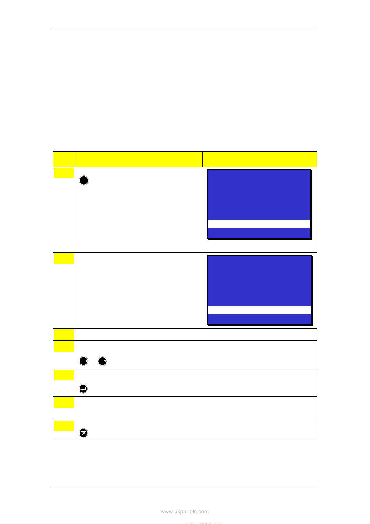
Show Status
www.ukpanels.com
10.4 Show Status – Fire Warnings
This menu gives detailed information on the current status of Fire
Warnings (Prealarms / Early Warnings) in the system. It provides the
following information:
• the location
• the exact time of activation
• an identification of the detectors (address)
• the type of detectors (optical, heat, etc.)
• all detectors in Fire Warning
The example below describes how to view the current status of Fire
Warnings.
Step Actions to be taken Display Indication
To enter the Main Menu, press
1
!
To select SHOW STATUS, press 1.
2
To select FIRE WARNINGS, press 2.
3
To move the cursor to the desired selection,
4
scroll with the arrow buttons
6
9
PQR
To view detailed zonal information for the
5
selected detection zone, press
or
YZ
MENU
1 SHOW STATUS
2 DISABLE
3 ENABLE
4 SYSTEM
5 SERVICE
SHOW STATUS
1 FIRE AL ARMS
2 FIRE WARNINGS
3 FAULTS
4 DISABLEMENTS
5 DETECTION ZONES IN TEST
6 OIL&GAS INHIBITED POINTS
7 ACTIVATED OUTPUTS
19:23
Total: 3
19:23
To view point(s) in Fire Warning for the selected
6
detection zone, press Action Digit 1 (SHOW
POINTS).
To return (each step backwards), press
7
Operator's Handbook, AutroSafe Interactive Fire Alarm System, Release 3, ASAFE-FO/FE Rev. E, 021105,
Autronica Fire and Security AS
Page 54
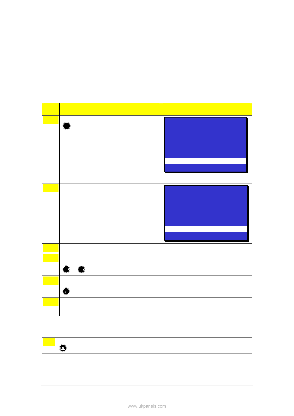
10.5 Show Status - Faults
www.ukpanels.com
This menu gives detailed information on the current status of faults in
the system. It provides the following information:
• the location
• an identification of the address
• the nature of the fault
• a detailed text
The example below describes how to view the current status of faults.
Step Actions to be taken Display Indication
Show Status
To enter the Main Menu, press
1
!
To select SHOW STATUS, press 1.
2
To select FAULTS, press 3.
3
To move the cursor to the desired selection,
4
scroll with the arrow buttons
6
9
PQR
To view detailed zonal information for the
5
selected detection zone, press
or
YZ
MENU
1 SHOW STATUS
2 DISABLE
3 ENABLE
4 SYSTEM
5 SERVICE
SHOW STATUS
1 FIRE AL ARMS
2 FIRE WARNINGS
3 FAULTS
4 DISABLEMENTS
5 DETECTION ZONES IN TEST
6 OIL&GAS INHIBITED POINTS
7 ACTIVATED OUTPUTS
19:23
Total: 3
19:23
To view point(s) in fault state for the selected
6
detection zone, press Action Digit 1 (SHOW
POINTS).
To return (each step backwards), press
7
Operator's Handbook, AutroSafe Interactive Fire Alarm System, Release 3, ASAFE-FO/FE Rev. E, 021105,
Comments:
Step 5 and 6 apply to Fault Warnings related to
Detection Zone / Points. The operator must in
this case always go via Detection Zone in order
to accept the fault warning (point).
Autronica Fire and Security AS
Page 55

Show Status
www.ukpanels.com
10.6 Show Status - Disablements
This menu gives detailed information on the current status of the
disablements in the system. It provides detailed information on the
disablement of the following:
• Detection Zones
• Points (fire detectors, manual call points)
• Fire Alarm Devices (FAD)
• Fire Alarm Routing Equipment (FARE)
• Outputs (FPE)
• Fault Warning Routing Equipment (FWRE)
• Immediate Output Actioning
• All
Step Actions to be taken Display Indication
To enter the Main Menu, press
1
!
To select SHOW STATUS, press 1.
2
To select DISABLEMENTS, press 4.
3
MENU
1 SHOW STATUS
2 DISABLE
3 ENABLE
4 SYSTEM
5 SERVICE
SHOW STATUS
1 FIRE AL ARMS
2 FIRE WARNINGS
3 FAULTS
4 DISABLEMENTS
5 DETECTION ZONES IN TEST
6 OIL&GAS INHIBITED POINTS
7 ACTIVATED OUTPUTS
SHOW STATUS
SHOW STATUS
DISABLEMENTS
DISABLEMENTS
1 DETECTION ZONES
1 DETECTION ZONES
2 POINTS
2 POINTS
3 FIRE ALARM DEVICES
3 FIRE ALARM DEVICES
4 FIRE ALARM ROUTING EQUIPMENT
4 FIRE ALARM ROUTING EQUIPMENT
5 OUTPUTS
5 OUTPUTS
6 FAULT WARNING ROUTING EQUIPMENT
6 FAULT WARNING ROUTING EQUIPMENT
7 IMMEDIATE OUTPUT ACTIONING
7 IMMEDIATE OUTPUT ACTIONING
8 ALL
8 ALL
19:23
Total: 3
19:23
19:23
19:23
The 3 steps above will lead you to Show Status - Disablements, where you can continue viewing the
status of the disablements (1-8), shown on the following page (step 4).
Operator's Handbook, AutroSafe Interactive Fire Alarm System, Release 3, ASAFE-FO/FE Rev. E, 021105,
Autronica Fire and Security AS
Page 56

www.ukpanels.com
Step Actions to be taken Display Indication
Show Status
To select, press the relevant number
4
(1-8).
1 Detection Zones
2 Points
3 Fire Alarm Devices
4 Fire Alarm Routing Equipment
5 Outputs
6 Fault Warning Routing Equipment
7 Immediate Output Actioning
8 All
To move the cursor to the desired selection,
5
scroll with the arrow buttons
6
9
PQR
To select and observe the status (in this
6
example menu selection 3; Fire Alarm Devices
or
YZ
is selected), press
If you want to enable the component, press
7
Action Digit 3 (ENABLE), then
If not, go to step 8.
To return (each step backwards), press
8
19:23
SHOW STATUS
SHOW STATUS
DISABLED FIRE ALARM DEVICEs
DISABLED FIRE ALARM DEVICEs
DISABLED FADs Total: 1
DISABLED FADs Total: 1
1 FAD1
1 FAD1
3: ENABLE
3: ENABLE
19:23
Operator's Handbook, AutroSafe Interactive Fire Alarm System, Release 3, ASAFE-FO/FE Rev. E, 021105,
Autronica Fire and Security AS
Page 57

Show Status
www.ukpanels.com
10.7 Show Status - Detection Zones in Test
This menu gives detailed information on the zones in test mode.
The example below describes how to view the current status of zones
in test mode.
Step Actions to be taken Display Indication
To enter the Main Menu, press
1
!
To select SHOW STATUS, press 1.
2
To select DETECTION ZONES IN TEST, press
3
5.
To move the cursor to the desired selection,
4
scroll with the arrow buttons
6
9
PQR
To view detailed zonal information for the
5
selected detection zone, press
or
YZ
MENU
1 SHOW STATUS
2 DISABLE
3 ENABLE
4 SYSTEM
5 SERVICE
SHOW STATUS
1 FIRE ALARMS
2 FIRE WARNINGS
3 FAULTS
4 DISABLEMENTS
5 DETECTION ZONES IN TEST
6 OIL&GAS INHIBITED POINTS
7 ACTIVATE D OUTPUTS
19:23
Total: 3
19:23
To view point(s) in test for the selected detection
6
zone, press Action Digit 1 (SHOW POINTS).
To return (each step backwards), press
7
Operator's Handbook, AutroSafe Interactive Fire Alarm System, Release 3, ASAFE-FO/FE Rev. E, 021105,
Autronica Fire and Security AS
Page 58

10.8 Show Status – Oil & Gas Inhibited Points
www.ukpanels.com
This menu gives detailed information on Oil & Gas Inhibited points.
The example below describes how to view the current status of Oil and
Gas Inhibited Points (detectors used in the Oil & Gas Market).
Step Actions to be taken Display Indication
Show Status
To enter the Main Menu, press
1
!
To select SHOW STATUS, press 1.
2
To select OIL&GAS INHIBITED POINTS, press
3
6.
To move the cursor to the desired selection,
4
scroll with the arrow buttons
6
9
PQR
To view detailed zonal information for the
5
selected detection zone, press
or
YZ
MENU
1 SHOW STATUS
2 DISABLE
3 ENABLE
4 SYSTEM
5 SERVICE
SHOW STATUS
1 FIRE ALARMS
2 FIRE WARNINGS
3 FAULTS
4 DISABLEMENTS
5 DETECTION ZONES IN TEST
6 OIL&GAS INHIBITED POINTS
7 ACTIVATE D OUTPUTS
19:23
Total: 3
19:23
To view Inhibited Point(s) for the selected
6
detection zone, press Action Digit 1 (SHOW
POINTS).
To return (each step backwards), press
7
Operator's Handbook, AutroSafe Interactive Fire Alarm System, Release 3, ASAFE-FO/FE Rev. E, 021105,
Autronica Fire and Security AS
Page 59

Show Status
www.ukpanels.com
10.9 Show Status – Activated Outputs
This menu gives detailed information on activated outputs.
The example below describes how to view the current status of
activated outputs.
Step Actions to be taken Display Indication
To enter the Main Menu, press
1
!
To select SHOW STATUS, press 1.
2
To select ACTIVATED OUTPUTS, press 7.
3
MENU
1 SHOW STATUS
2 DISABLE
3 ENABLE
4 SYSTEM
5 SERVICE
SHOW STATUS
1 FIRE ALARMS
2 FIRE WARNINGS
3 FAULTS
4 DISABLEMENTS
5 DETECTION ZONES IN TEST
6 OIL&GAS INHIBITED POINTS
7 ACTIVATE D OUTPUTS
SHOW STATUS
SHOW STATUS
ACTIVATED OUTPUTS
ACTIVATED OUTPUTS
1 DOOR CONTRO L UNITS
1 DOOR CONTRO L UNITS
2 LOW LOCATION LIGHT UNITS
2 LOW LOCATION LIGHT UNITS
3 STANDARD CONTROL UNITS
3 STANDARD CONTROL UNITS
4 OTHER OUTPUTS
4 OTHER OUTPUTS
5 ALL
5 ALL
19:23
Total: 3
19:23
19:23
19:23
The 3 steps above will lead you to Show Status – Acitivated Outputs, where you can continue viewing
the status of the activated outputs (1-5), shown on the following page (step 4).
Operator's Handbook, AutroSafe Interactive Fire Alarm System, Release 3, ASAFE-FO/FE Rev. E, 021105,
Autronica Fire and Security AS
Page 60

www.ukpanels.com
Step Actions to be taken Display Indication
Show Status
To select, press the relevant number
4
(1-5).
1 Door Control Units
2 Low Location Light Units
3 Standard Control Units
4 Other Outputs
5 All
To move the cursor to the desired selection,
5
scroll with the arrow buttons
6
9
PQR
To select and observe the status (in this
6
example menu selection 1; door control units is
or
YZ
selected), press
To return (each step backwards), press
7
SHOW STATUS
SHOW STATUS
AVCITVATED OU TPUTS>DMCU
AVCITVATED OU TPUTS>DMCU
1*1dc7
1*1dc7
19:23
19:23
TOTAL 1
TOTAL 1
Operator's Handbook, AutroSafe Interactive Fire Alarm System, Release 3, ASAFE-FO/FE Rev. E, 021105,
Autronica Fire and Security AS
Page 61

Disabling
www.ukpanels.com
11. Disabling
11.1 General
From the Disable menu you can disable the following:
• Detection Zones
• Points (fire detectors, manual call points)
• Fire Alarm Devices (FAD)
• Fire Alarm Routing Equipment (FARE)
• Outputs
• Fault Warning Routing Equipment (FWRE)
• Immediate Output Actioning
When disabling components, a disablement time is given. The
disablement time can be increased for already disabled components
by entering the disable menu.
For information on Disablement Sources, refer to chapter 3.14.
11.2 Disable Menu
Fire Alarm Routing Equipment
Fire Alarm Routing Equipment
Fault Warning Routing Equipment
Fault Warning Routing Equipment
Disable
Disable
Detection Zones
Detection Zones
Select DZ
Select DZ
Select disablement time
Select disablement time
Points
Points
Select Point
Select Point
Select disablement time
Select disablement time
Fire Alarm Devices
Fire Alarm Devices
Select Single Unit
Select Single Unit
Select All in Alarm Zone
Select All in Alarm Zone
Select disablement time
Select disablement time
Select FARE
Select FARE
Select disablement time
Select disablement time
Outputs
Outputs
Select Single Output
Select Single Output
Select Single Output
Select Single Output
Select All in Operation Zone
Select All in Operation Zone
Select disablement time
Select disablement time
Select FWRE
Select FWRE
Select disablement time
Select disablement time
Immediate Output Actioning
Immediate Output Actioning
Select All Areas
Select All Areas
Select Specific Area
Select Specific Area
Figure 11-1: Disable Menu.
Operator's Handbook, AutroSafe Interactive Fire Alarm System, Release 3, ASAFE-FO/FE Rev. E, 021105,
Autronica Fire and Security AS
Page 62

11.3 Indications on the Operator Panel
www.ukpanels.com
When one or several disablements exist, the Function Disabled
indicator on the Operator Panel will show a yellow steady light. The
panel’s display will indicate that a disablement exists (as shown in the
example below).
DISABLEMENTS
DISABLED DZs
1 CANTEEN
Figure 11-2: Disablement - indications on the display
19:23
Total: 1
Total: 1
Disabling
11.4 Disabling Activated / Deactivated Components
When you disable an active component, for example, a sounder
issuing an alarm signal, the component will immediately switch to the
OFF state without any user notification and/or confirmation cause.
A disablement of a deactivated component, for example, a sounder
not issuing an alarm signal, will have no immediate effect on system
operation.
Both activated and deactivated disabled components will remain
switched off until enabled.
11.5 Disabling Detection Zones
When you disable a Detection Zone - all points within the specified
detection zone will be disabled. A detection zone will not be indicated
as disabled unless all points within the zone have been disabled.
A disablement time can be set. When the disablement time expires,
the detection zone will automatically be enabled. The detection zone
can also be enabled manually from the Enable Menu.
Operator's Handbook, AutroSafe Interactive Fire Alarm System, Release 3, ASAFE-FO/FE Rev. E, 021105,
Autronica Fire and Security AS
Page 63

Disabling
www.ukpanels.com
11.6 Disabling Points
When you disable a Point (fire detectors / manual call-points), no
alarm signal or fault signal from this point will be sent in the event of an
alarm / fault.
A disablement time can be set. When the disablement time expires,
the point(s) will automatically be enabled. The point(s) can also be
enabled manually from the Enable Menu.
If all points in a detection zone are disabled, the detection zone will be
indicated as disabled. If at least one point within this detection zone is
enabled manually, the detection zone will be indicated as enabled. If
the points are given different disablement times, the detection zone will
be automatically indicated as enabled when the first point is enabled
(i.e. when the point with the shortest disablement time is enabled).
11.7 Disabling Fire Alarm Devices
When you disable a Fire Alarm Device (FAD), the output which
controls the FAD will be disabled. The FAD will thus give no audible
indication.
You can disable a single unit (FAD) / alarm circuit, or all units (FADs)
in a selected Alarm Zone.
A disablement time can be set. When the disablement time expires,
the FAD(s) will automatically be enabled. The single FAD or all FADs
in a selected Alarm Zone can also be enabled manually from the
Enable Menu.
11.8 Disabling Fire Alarm Routing Equipment
When you disable Fire Alarm Routing Equipment (FARE), the output
which controls such equipment will be disabled. In the event of an
alarm, no fire alarm signals / fault signals will be sent to the fire
brigade.
A disablement time can be set. When the disablement time expires,
the Fire Alarm Routing Equipment will automatically be enabled. The
equipment can also be enabled manually from the Enable Menu.
11.9 Disabling Outputs
When you disable outputs which control Fire Protection Equipment
(FPE), in the event of an alarm / fault, no signals will be sent to trigger
the equipment. You can disable a single output, or all outputs in the
Operation Zone.
A disablement time can be set. When the disablement time expires,
the outputs which control Fire Protection Equipment will automatically
be enabled. The outputs can also be enabled manually from the
Enable Menu.
Operator's Handbook, AutroSafe Interactive Fire Alarm System, Release 3, ASAFE-FO/FE Rev. E, 021105,
Autronica Fire and Security AS
Page 64

11.10 Disabling Fault Warning Routing Equipment
www.ukpanels.com
When you disable Fault Warning Routing Equipment (FWRE), the
output which controls such equipment will be disabled. In the event of
a fault, no fault warning signals will be sent to, for example, the
security firm.
A disablement time can be set. When the disablement time expires,
the Fault Warning Routing Equipment will automatically be enabled.
The equipment can also be enabled manually from the Enable Menu.
11.11 Disabling Immediate Output Actioning
In an alarm situation, the actioning of outputs in a Delayed Action
detection zone can be delayed (refer to Delayed Action detection
zones, page 26). To achieve a delay, Immediate Output Actioning
must be disabled.
It is possible to disable immediate output actioning for all Day / Night
areas or for selected Day / Night areas.
Note: A Day / Night area encompasses one or more detection zones
within the same operation zone.
The delay affects the actioning of outputs to Fire Alarm Devices (FAD),
Fire Alarm Routing Equipment (FARE) and/or Fire Protection
Equipment (FPE).
Note that an alarm from a manual call-point will normally (point delay
OFF) give immediate ouput actioning even though the immediate
output actioning has been disabled.
The function is useful in situations where you want to disable
immediate output actioning at special periods to avoid causing any
unnecessary disturbance.
Disabling
Operator's Handbook, AutroSafe Interactive Fire Alarm System, Release 3, ASAFE-FO/FE Rev. E, 021105,
Autronica Fire and Security AS
Page 65

Disabling
www.ukpanels.com
11.12 How to Execute Commands from the
Disable Menu
The example below shows how to disable a Detection Zone. The
similar procedure applies to all other selections (1-7).
Step Actions to be taken Display Indication
To enter the Main Menu, press
1
!
To select DISABLE, press 2.
2
To select, press the relevant number, in this
3
example 1 (DETECTION ZONES).
MENU
1 SHOW STATUS
2 DISABLE
3 ENABLE
4 SYSTEM
5 SERVICE
DISABLE
DISABLE
1 DETECTION ZONES
1 DETECTION ZONES
2 POINTS
2 POINTS
3 FIRE ALARM DEVICES
3 FIRE ALARM DEVICES
4 FIRE ALARM ROUTING EQUIPMENT
4 FIRE ALARM ROUTING EQUIPMENT
5 OUTPUTS
5 OUTPUTS
6 FAULT WARNING ROUTING EQUIPMENT
6 FAULT WARNING ROUTING EQUIPMENT
7 IMMEDIATE OUTPUT ACTIONING
7 IMMEDIATE OUTPUT ACTIONING
DISABLE
DISABLE
DETECTION ZO NES
DETECTION ZO NES
Total: 3
19:23
19:23
Total: 3
Total: 3
19:23
19:23
19:23
19:23
19:23
Use the keyboard to enter text into the input box
4
-
OR ,- as shown in this example:
press
then move the cursor to the desired selection
(OFFICES) by scrolling with the arrow buttons
6
9
PQR
or
YZ
KITCHEN
KITCHEN
CANTEEN
CANTEEN
OFFICES
OFFICES
WORKSHOP
WORKSHOP
DISABLE
DISABLE
DETECTION ZONES
DETECTION ZONES
KITCHEN
KITCHEN
CANTEEN
CANTEEN
OFFICES
OFFICES
WORKSHOP
WORKSHOP
19:23
19:23
Operator's Handbook, AutroSafe Interactive Fire Alarm System, Release 3, ASAFE-FO/FE Rev. E, 021105,
Autronica Fire and Security AS
Page 66
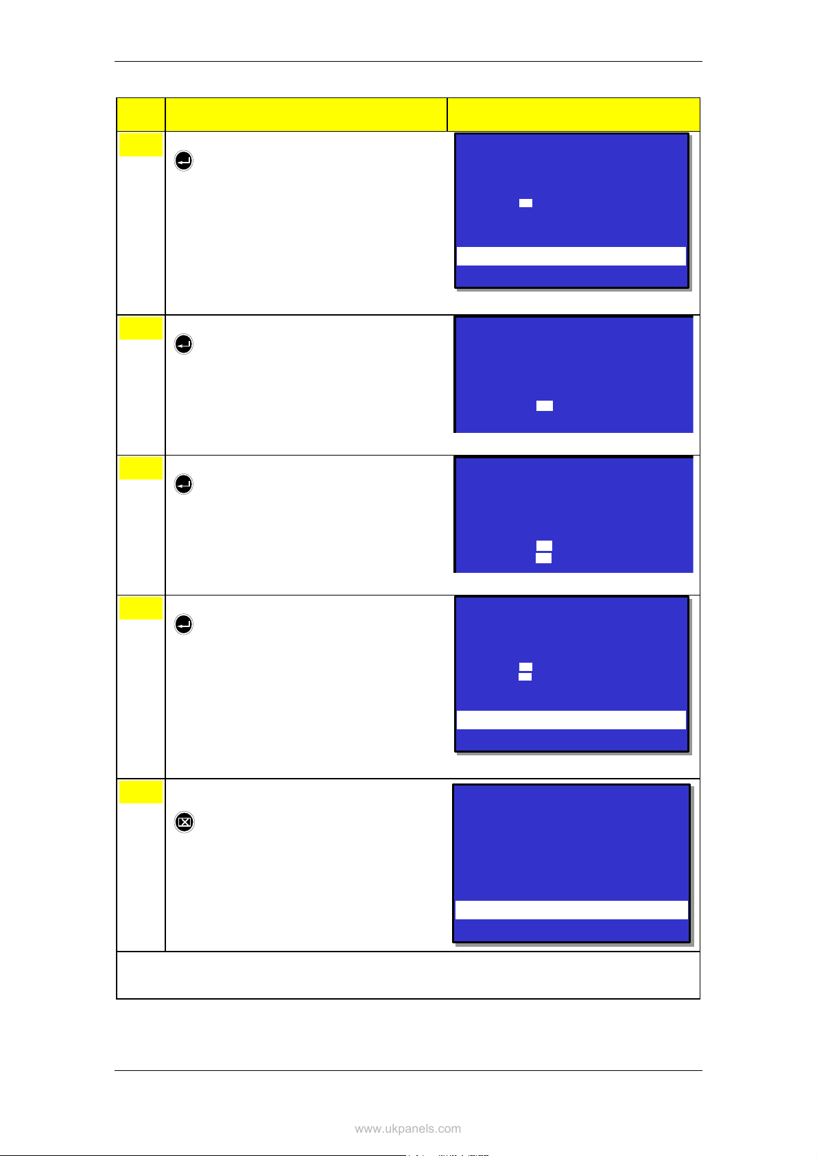
Step Actions to be taken Display Indication
www.ukpanels.com
5
Press
DISABLE
DISABLE
DETECTION ZONES
DETECTION ZONES
OFFICES
OFFICES
Disablement time
Disablement time
Hour :
Hour :
Min. :
Min. :
Execute command
Execute command
0
0
Disabling
19:23
19:23
Enter hours, then press
6
Enter minutes, then press
7
To execute the command, press
8
DISABLE
DISABLE
DETECTION ZONES
DETECTION ZONES
OFFICES
OFFICES
Disablement time
Disablement time
Hour :
Hour :
Min. :
Min. :
DISABLE
DISABLE
DETECTION ZONES
DETECTION ZONES
OFFICES
OFFICES
Disablement time
Disablement time
Hour :
Hour :
Min. :
Min. :
DISABLE
DISABLE
DETECTION ZONES
DETECTION ZONES
OFFICES
OFFICES
Disablement time
Disablement time
Hour :
Hour :
02
02
Min. :
Min. :
5
5
Execute command
Execute command
02
02
5
5
02
02
19:23
19:23
To return to the DISABLE menu immediately,
9
press
Operator's Handbook, AutroSafe Interactive Fire Alarm System, Release 3, ASAFE-FO/FE Rev. E, 021105,
DISABLE
DISABLE
Comments:
If the Close button is not pressed, the DISABLE
menu will appear automatically after a short
moment.
Autronica Fire and Security AS
Page 67
1 DETECTION ZONES
1 DETECTION ZONES
2 POINTS
2 POINTS
3 FIRE ALAR M DEVICES
3 FIRE ALAR M DEVICES
4 FIRE ALAR M ROUTING EQ UIPMENT
4 FIRE ALAR M ROUTING EQ UIPMENT
5 OUTPUTS
5 OUTPUTS
6 FAULT WARNING ROUTING EQUIPMENT
6 FAULT WARNING ROUTING EQUIPMENT
7 IMMEDIATE OUTPUT ACTIONING
7 IMMEDIATE OUTPUT ACTIONING
19:23
19:23
Total: 3
Total: 3
19:23
19:23

Enabling
www.ukpanels.com
12. Enabling
12.1 General
From the Enable menu you can enable the following:
• Detection Zones
• Points (fire detectors, manual call points)
• Fire Alarm Devices (FAD)
• Fire Alarm Routing Equipment (FARE)
• Outputs
• Fault Warning Routing Equipment (FWRE)
• Immediate Output Actioning
12.2 Enable Menu
Fire Alarm Routing Equipment
Fire Alarm Routing Equipment
Enable
Enable
Detection Zones
Detection Zones
Select DZ
Select DZ
Points
Points
Select Point
Select Point
Fire Alarm Devices
Fire Alarm Devices
Select Single Unit
Select Single Unit
Select All in Alarm Zone
Select All in Alarm Zone
Select FARE
Select FARE
Outputs
Outputs
Select Single Output
Select Single Output
All in Operation Zone
All in Operation Zone
Fault Warning Routing Equipment
Fault Warning Routing Equipment
Select FWRE
Select FWRE
Immediate Output Actioning
Immediate Output Actioning
Select All Areas
Select All Areas
Select Specific Area
Select Specific Area
Figure 12-1: Enable Menu
Operator's Handbook, AutroSafe Interactive Fire Alarm System, Release 3, ASAFE-FO/FE Rev. E, 021105,
Autronica Fire and Security AS
Page 68

12.3 Enabling Activated / Deactivated Components
www.ukpanels.com
Setting the arm state of a disabled deactivated component to
ENABLED will have no immediate effect on system operation. The
component will remain deactivated until its activation state is set to an
active state (on alarm or on command).
12.4 Enabling Detection Zones
When you enable a Detection Zone - all points within the specified
detection zone will be enabled - except for those that are individually
disabled as described in the subsequent chapter. A detection zone will
not be indicated as enabled unless at least one point within the zone is
enabled.
12.5 Enabling Points
Enabling
When a Point (fire detectors / manual call-points) is enabled (manually
or when the disablement time expires), alarm signals will be sent from
this point in the event of an alarm.
If all points in a detection zone are disabled, the detection zone will be
indicated as disabled. If at least one point within this detection zone is
enabled, the detection zone will be indicated as enabled. If the points
are given different disablement times, the detection zone will be
automatically indicated as enabled when the first point is enabled (i.e.
when the point with the shortest disablement time is enabled).
12.6 Enabling Fire Alarm Devices
When you enable a Fire Alarm Device (FAD), the output which
controls the FAD will be enabled. The FAD will now give an audible
indication.
You can enable a single unit (FAD) / alarm circuit, or all units (FADs) in
a selected Alarm Zone.
Operator's Handbook, AutroSafe Interactive Fire Alarm System, Release 3, ASAFE-FO/FE Rev. E, 021105,
Autronica Fire and Security AS
Page 69

Enabling
www.ukpanels.com
12.7 Enabling Fire Alarm Routing Equipment
When you enable Fire Alarm Routing Equipment (FARE), the output
which controls such equipment will be enabled. In the event of an
alarm, fire alarm signals may be sent to the fire brigade (configurable).
12.8 Enabling Outputs
When you enable outputs which control Fire Protection Equipment
(FPE), in the event of an alarm, signals will be sent to trigger the
equipment. You can enable a single output, or all outputs in the
Operation Zone.
12.9 Enabling Fault Warning Routing Equipment
When you enable Fault Warning Routing Equipment (FWRE), the
output which controls such equipment will be enabled. In the event of a
fault, fault warning signals will be sent to, for example, the security
firm.
12.10 Enabling Immediate Output Actioning
When enabling Immediate Output Actioning, there will be no delay on
the actioning of outputs to Fire Alarm Devices (FAD) and/or Fire Alarm
Routing Equipment (FARE) in zones configured as Delayed Action
Detection Zones, Delayed Coincidence Detection Zones or SOLAS
Detection Zones.
It is possible to enable immediate output actioning for all Day / Night
areas or for selected Day / Night areas.
Operator's Handbook, AutroSafe Interactive Fire Alarm System, Release 3, ASAFE-FO/FE Rev. E, 021105,
Autronica Fire and Security AS
Page 70
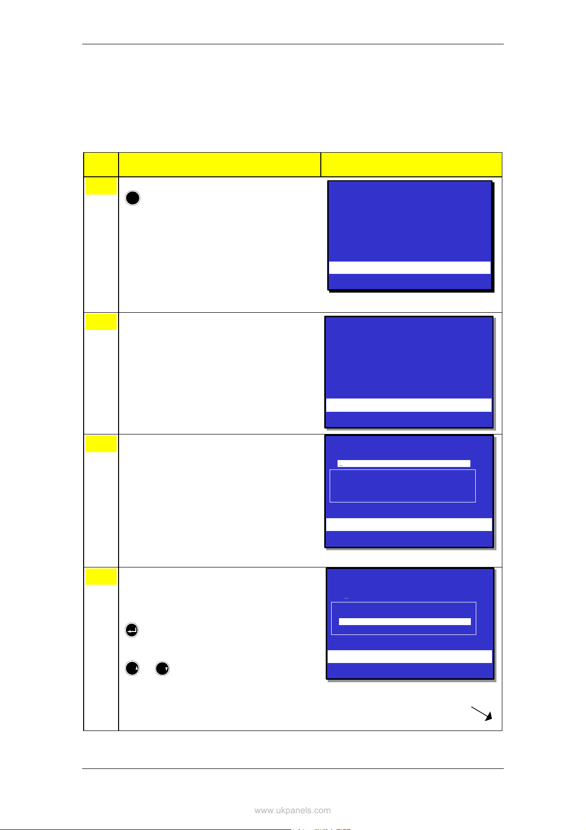
12.11 How to Execute Commands from the
www.ukpanels.com
Enable Menu
The example below shows how to enable a Detection Zone. The
similar procedure applies to all other selections (1-7).
Step Actions to be taken Display Indication
Enabling
To enter the Main Menu, press
1
!
To select ENABLE, press 3.
2
To select, press the relevant number, in this
3
example 1 (DETECTION ZONES).
MENU
1 SHOW STATUS
2 DISABLE
3 ENABLE
4 SYSTEM
5 SERVICE
ENABLE
ENABLE
1 DETECTION Z ONES
1 DETECTION Z ONES
2 POINTS
2 POINTS
3 FIRE ALARM DEVICES
3 FIRE ALARM DEVICES
4 FIRE ALARM ROUTING EQUIPMENT
4 FIRE ALARM ROUTING EQUIPMENT
5 OUTPUTS
5 OUTPUTS
6 FAULT WARNING RO UTING EQUIPMENT
6 FAULT WARNING RO UTING EQUIPMENT
7 IMMEDIATE OUTP UT ACTIONING
7 IMMEDIATE OUTP UT ACTIONING
ENABLE
ENABLE
DETECTION ZO NES
DETECTION ZO NES
19:23
Total: 3
19:23
19:23
19:23
19:23
Use the keyboard to enter text into the input box
4
-
OR ,- as shown in this example:
press
then move the cursor to the desired selection
(OFFICES) by scrolling with the arrow buttons
6
9
PQR
or
YZ
KITCHEN
KITCHEN
CANTEEN
CANTEEN
OFFICES
OFFICES
WORKSHOP
WORKSHOP
ENABLE
ENABLE
DETECTION ZONES
DETECTION ZONES
KITCHEN
KITCHEN
CANTEEN
CANTEEN
OFFICES
OFFICES
WORKSHOP
WORKSHOP
19:23
19:23
Operator's Handbook, AutroSafe Interactive Fire Alarm System, Release 3, ASAFE-FO/FE Rev. E, 021105,
Autronica Fire and Security AS
Page 71

www.ukpanels.com
Step Actions to be taken Display Indication
Press
5
To execute the command, press
6
ENABLE
ENABLE
DETECTION ZONES
DETECTION ZONES
OFFICES
OFFICES
Enablement time: 20:45
Enablement time: 20:45
Execute command
Execute command
ENABLE
ENABLE
DETECTION ZONES
DETECTION ZONES
OFFICES
OFFICES
Enablement time: 20:45
Enablement time: 20:45
Successfully Completed
Successfully Completed
19:23
19:23
19:23
19:23
To return to the ENABLE menu immediately,
7
press
Comments:
19:23
ENABLE
ENABLE
1 DETECTION Z ONES
1 DETECTION Z ONES
2 POINTS
2 POINTS
3 FIRE ALARM DEVICES
3 FIRE ALARM DEVICES
4 FIRE ALARM ROUTING EQUIPMENT
4 FIRE ALARM ROUTING EQUIPMENT
5 OUTPUTS
5 OUTPUTS
6 FAULT WARNING RO UTING EQUIPMENT
6 FAULT WARNING RO UTING EQUIPMENT
7 IMMEDIATE OUTP UT ACTIONING
7 IMMEDIATE OUTP UT ACTIONING
19:23
If the Close button is not pressed, the ENABLE
menu will appear automatically after a short
moment.
Operator's Handbook, AutroSafe Interactive Fire Alarm System, Release 3, ASAFE-FO/FE Rev. E, 021105,
Autronica Fire and Security AS
Page 72

13. System Menu
www.ukpanels.com
13.1 Introduction
The System Menu allows authorized personnel to:
• set/change date and time
• view the current program version and project information
(identification, customer name, version of site configuration data
and configuration tool)
• enter access level 3 (to reconfigure or maintain site specific data),
set/change password
• turn printer ON/OFF, feed paper
• change language (toggle between English / local language)
• manually initialize the AutroSafe Interactive Fire Alarm System
• start / stop automatic Day / Night Operation, show timers
Only users with access level 2 (key), 3 (password restricted) or a
higher access level are allowed to do changes in the system menu.
System Menu
13.2 System Menu
System
System
Date and Time
Date and Time
Read /set date and time
Read /set date and time
Information
Information
Program
Program
Configuration data
Configuration data
Access Level 3
Access Level 3
Printer ON
Printer ON
Printer OFF
Printer OFF
Paper feed
Paper feed
Change Language
Change Language
Enter Access Level 3
Enter Access Level 3
Leave Access Level 3
Leave Access Level 3
Set Password
Set Password
Printer
Printer
Initialize
Initialize
Day / Night Timers
Day / Night Timers
Start
Start
Stop
Stop
Show Running Timers
Show Running Timers
Figure 13-1: System Menu
Operator's Handbook, AutroSafe Interactive Fire Alarm System, Release 3, ASAFE-FO/FE Rev. E, 021105,
Autronica Fire and Security AS
Page 73

System Menu
www.ukpanels.com
13.3 How to Set / Change Date and Time
The procedure below describes how to set / change date and time.
Step Actions to be taken Display Indication
To enter the Main Menu, press
1
!
To select SYSTEM, press 4.
2
To select DATE AND TIME, press 1.
3
MENU
1 SHOW STATUS
2 DISABLE
3 ENABLE
4 SYSTEM
5 SERVICE
SYSTEM
SYSTEM
1 DATE AND TIME
1 DATE AND TIME
2 INFORMATION
2 INFORMATION
3 ACCESS LEVEL 3
3 ACCESS LEVEL 3
4 PRINTER
4 PRINTER
5 CHANGE LANGUAGE
5 CHANGE LANGUAGE
6 INITIALIZE
6 INITIALIZE
7 DAY/NIGHT TIMERS
7 DAY/NIGHT TIMERS
SYSTEM
SYSTEM
DATE AND TIME
DATE AND TIME
Current dat e: 1998-11-26
Current dat e: 1998-11-26
Current time : 15:59
Current time : 15:59
New date (YYYYMMDD) : 19981126
New date (YYYYMMDD) : 19981126
New time (hh mmss) :
New time (hh mmss) :
19:23
Total: 3
19:23
19:23
19:23
19:23
If necessary, enter the correct date
4
(8 digits; YYYYMMDD), then press
Enter the correct time (6 digits; hhmmss), then
5
press
twice.
Operator's Handbook, AutroSafe Interactive Fire Alarm System, Release 3, ASAFE-FO/FE Rev. E, 021105,
Autronica Fire and Security AS
Comments:
Page 74
The date will appear automatically. If the wrong
date appears, you can overwrite with the correct
date.
SYSTEM
SYSTEM
DATE AND TIME
DATE AND TIME
Current date: 1998-11-26
Current date: 1998-11-26
Current time: 15:59
Current time: 15:59
New date (YYYYMMDD) : 19981 126
New date (YYYYMMDD) : 19981 126
New time (hhmmss) :
New time (hhmmss) :
SYSTEM
SYSTEM
DATE AND TIME
DATE AND TIME
Current date: 1998-11-26
Current date: 1998-11-26
Current time: 15:59
Current time: 15:59
New date (YYYYMMDD) : 1 9981126
New date (YYYYMMDD) : 1 9981126
New time (hhmmss) : 142400
New time (hhmmss) : 142400
Successfully Completed
Successfully Completed
19:23
19:23
19:23
19:23

13.4 How to View Current Program Version
www.ukpanels.com
The procedure below describes how to view the current program
version.
Step Actions to be taken Display Indication
System Menu
To enter the Main Menu, press
1
!
To select SYSTEM, press 4.
2
To select INFORMATION, press 2.
3
MENU
1 SHOW STATUS
2 DISABLE
3 ENABLE
4 SYSTEM
5 SERVICE
SYSTEM
SYSTEM
1 DATE AND TIME
1 DATE AND TIME
2 INFORMATION
2 INFORMATION
3 ACCESS LEVEL 3
3 ACCESS LEVEL 3
4 PRINTER
4 PRINTER
5 CHANGE LANGUAGE
5 CHANGE LANGUAGE
6 INITIALIZE
6 INITIALIZE
7 DAY/NIGHT TIMERS
7 DAY/NIGHT TIMERS
SYSTEM
SYSTEM
INFO
INFO
CONFIG
CONFIG
Program/Model: 1.12.5
Program/Model: 1.12.5
Site spec. data: OBS Rev A
Site spec. data: OBS Rev A
Tool: ULLA
Tool: ULLA
Download date: 1999-03-01
Download date: 1999-03-01
CODE
CODE
Version: 1.0.0
Version: 1.0.0
19:23
Total: 3
19:23
19:23
19:23
19:23
Operator's Handbook, AutroSafe Interactive Fire Alarm System, Release 3, ASAFE-FO/FE Rev. E, 021105,
Autronica Fire and Security AS
Page 75

System Menu
www.ukpanels.com
13.5 How to Enter Access Level 3 / Set Password
13.5.1 Introduction
This menu describes how to enter/leave Access Level 3 and to set a
new password (requires Access Level 3). All user interface controls
are classified as belonging to one of the four different access levels
described below:
Access
Level
1 No key or password
2 Access by key.
3 Password restricted. Accessible by persons trained and authorized to do
4 Mechanical tool. Accessible by persons doing repair work and changing
Access Remedy Description
Accessible by members of the general public. All mandatory
required.
indications are visible at access level 1 without prior manual
intervention.
Accessible by persons having a specified responsibility for
safety.
reconfiguration of site specific data and maintenance
according to the manufacturer’s published instruction.
firmware.
Step Actions to be taken Display Indication
To enter the Main Menu, press
1
!
To select SYSTEM, press 4.
2
To select ACCESS LEVEL 3, press 3.
3
MENU
1 SHOW STATUS
2 DISABLE
3 ENABLE
4 SYSTEM
5 SERVICE
SYSTEM
SYSTEM
1 DATE AND TIME
1 DATE AND TIME
2 INFORMATION
2 INFORMATION
3 ACCESS LEVEL 3
3 ACCESS LEVEL 3
4 PRINTER
4 PRINTER
5 CHANGE LANGUAGE
5 CHANGE LANGUAGE
6 INITIALIZE
6 INITIALIZE
7 DAY/NIGHT TIMERS
7 DAY/NIGHT TIMERS
SYSTEM
SYSTEM
ACCESS LEVEL 3
ACCESS LEVEL 3
1 ENTER ACCESS LEVEL 3
1 ENTER ACCESS LEVEL 3
2 LEAVE ACCESS LEVEL 3
2 LEAVE ACCESS LEVEL 3
3 SET PASSWORD
3 SET PASSWORD
19:23
Total: 3
19:23
19:23
19:23
19:23
Comments:
Operator's Handbook, AutroSafe Interactive Fire Alarm System, Release 3, ASAFE-FO/FE Rev. E, 021105,
Autronica Fire and Security AS
Page 76
From here you can enter / leave access level 3,
or set a new password (see the next steps on
the following pages).

13.5.2 Enter Access Level 3
www.ukpanels.com
…..continued from previous page.
Step Actions to be taken Display Indication
System Menu
To enter ACCESS LEVEL 3, press 1.
4
Enter the password, then press
5
twice.
SYSTEM
SYSTEM
ACCESS LEVEL 3/ENT ER ACCESS LEVEL 3
ACCESS LEVEL 3/ENT ER ACCESS LEVEL 3
Enter pa ssword:
Enter pa ssword:
SYSTEM
SYSTEM
ACCESS LEVEL 3/ENTER ACCESS LEVEL 3
ACCESS LEVEL 3/ENTER ACCESS LEVEL 3
Enter password: ****
Enter password: ****
Successfully Completed
Successfully Completed
19:23
19:23
19:23
19:23
13.5.3 Leave Access Level 3
…..continued from previous page
Step Actions to be taken Display Indication
To enter LEAVE ACCESS LEVEL 3, press 2.
4
Press
5
SYSTEM
SYSTEM
ACCESS LEVEL 3/LEAVE ACCESS LEVEL 3
ACCESS LEVEL 3/LEAVE ACCESS LEVEL 3
Are you sure you want to leave
Are you sure you want to leave
access level 3? YES
access level 3? YES
SYSTEM
SYSTEM
ACCESS LEVEL 3/LEAVE ACCESS LEVEL 3
ACCESS LEVEL 3/LEAVE ACCESS LEVEL 3
Are you sure you want to leave
Are you sure you want to leave
access level 3?
access level 3?
19:23
19:23
19:23
19:23
Operator's Handbook, AutroSafe Interactive Fire Alarm System, Release 3, ASAFE-FO/FE Rev. E, 021105,
Autronica Fire and Security AS
Page 77

System Menu
www.ukpanels.com
13.5.4 Set (or Change) Password
…..continued from step 3 (ACCESS LEVEL 3).
Step Actions to be taken Display Indication
To set password, press 3.
4
Enter new password, then press
5
Verify by entering the new password, then press
6
twice.
SYSTEM
ACCESS LEVEL 3 / SET PASSWORD
New password :
Verify password:
***
SYSTEM
ACCESS LEVEL 3 / SET PASSWORD
New password :
Verify password:
***
*
SYSTEM
ACCESS LEVEL 3 / SET PASSWORD
New password :
Verify password:
***
*
***
*
19:23
19:23
19:23
Successfully Completed
Operator's Handbook, AutroSafe Interactive Fire Alarm System, Release 3, ASAFE-FO/FE Rev. E, 021105,
Autronica Fire and Security AS
Page 78

13.6 How to Feed Paper
www.ukpanels.com
The procedure below describes how to feed the paper.
Step Actions to be taken Display Indication
System Menu
To enter the Main Menu, press
1
!
To select SYSTEM, press 4.
2
To select PRINTER, press 4.
3
MENU
1 SHOW STATUS
2 DISABLE
3 ENABLE
4 SYSTEM
5 SERVICE
SYSTEM
SYSTEM
1 DATE AND TIME
1 DATE AND TIME
2 INFORMATION
2 INFORMATION
3 ACCESS LEVEL 3
3 ACCESS LEVEL 3
4 PRINTER
4 PRINTER
5 CHANGE LANGUAGE
5 CHANGE LANGUAGE
6 INITIALIZE
6 INITIALIZE
7 DAY/NIGHT TIMERS
7 DAY/NIGHT TIMERS
SYSTEM
PRINTER
1 PAPER FEED
19:23
Total: 3
19:23
19:23
19:23
To feed paper, press 1.
4
Operator's Handbook, AutroSafe Interactive Fire Alarm System, Release 3, ASAFE-FO/FE Rev. E, 021105,
Autronica Fire and Security AS
Page 79
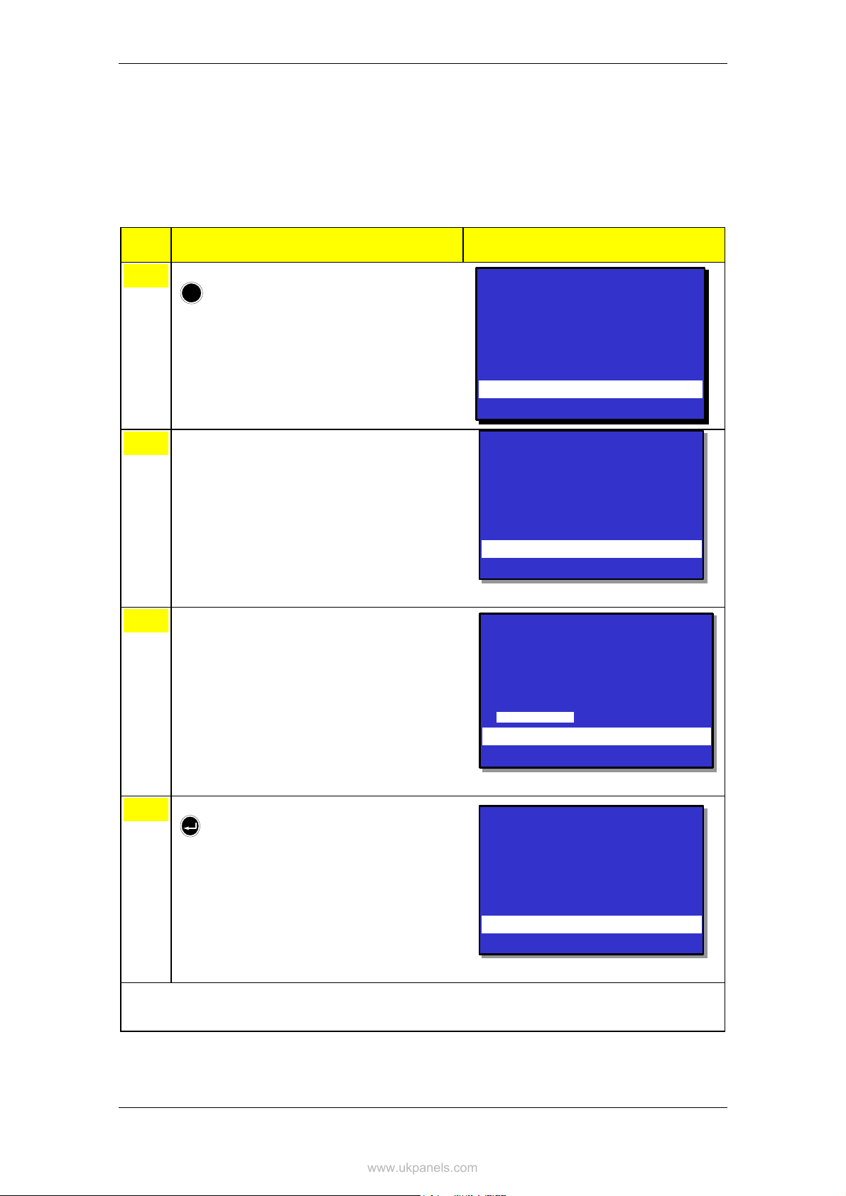
System Menu
www.ukpanels.com
13.7 How to Change Language
This menu allows you to determine the language which is to be used
(English / local language) for a panel. A change in language has to be
done locally on each panel.
Step Actions to be taken Display Indication
To enter the Main Menu, press
1
!
To select SYSTEM, press 4.
2
To select CHANGE LANGUAGE, press 5.
3
MENU
1 SHOW STATUS
2 DISABLE
3 ENABLE
4 SYSTEM
5 SERVICE
SYSTEM
SYSTEM
1 DATE AND TIME
1 DATE AND TIME
2 INFORMATION
2 INFORMATION
3 ACCESS LEVEL 3
3 ACCESS LEVEL 3
4 PRINTER
4 PRINTER
5 CHANGE LAN GUAGE
5 CHANGE LAN GUAGE
6 INITIALIZE
6 INITIALIZE
7 DAY/NIGHT TIMERS
7 DAY/NIGHT TIMERS
SYSTEM
CHANGE LANGUAGE
NEW LANG UAGE:
Native
19:23
Total: 3
19:23
19:23
19:23
To accept the language, press
4
Operator's Handbook, AutroSafe Interactive Fire Alarm System, Release 3, ASAFE-FO/FE Rev. E, 021105,
Comments:
Autronica Fire and Security AS
Page 80
The System Menu will after a few seconds
appear in the native language (shown in English
above).
Execute command
SYSTEM
SYSTEM
1 DATE AND TIME
1 DATE AND TIME
2 INFORMATION
2 INFORMATION
3 ACCESS LEVEL 3
3 ACCESS LEVEL 3
4 PRINTER
4 PRINTER
5 CHANGE LAN GUAGE
5 CHANGE LAN GUAGE
6 INITIALIZE
6 INITIALIZE
7 DAY/NIGHT TIMERS
7 DAY/NIGHT TIMERS
19:23
19:23

13.8 How to Initialize the Fire Alarm System
www.ukpanels.com
The AutroSafe Interactive Fire Alarm System is automatically initialized
when the panel is turned on. However, in certain cases it may be
necessary to manually initialize the panel. In situations where the loop
topology has been changed in some way, for example, two detectors
have changed places or have been removed, a service command
(Clear Topology) has to be executed. When this command is
completed, the control panel has to be initialized manually.
The procedure below describes how to manually initialize the fire
alarm system.
Step Actions to be taken Display Indication
System Menu
To enter the Main Menu, press
1
!
To select SYSTEM, press 4.
2
To select INITIALIZE, press 6.
3
MENU
SYSTEM
SYSTEM
1 DATE AND TIM E
1 DATE AND TIM E
2 INFORMATI ON
2 INFORMATI ON
3 ACCESS LEVEL 3
3 ACCESS LEVEL 3
4 PRINTER
4 PRINTER
5 CHANGE LANGUAGE
5 CHANGE LANGUAGE
6 INITIALIZE
6 INITIALIZE
7 DAY/NIGHT TIMERS
7 DAY/NIGHT TIMERS
SYSTEM
INITIALIZE
Start INIT
Phase 1:
Phase 2:
Phase 3:
Phase 4:
Info:
3 PAPER FEED
1 SHOW STATUS
2 DISABLE
3 ENABLE
4 SYSTEM
5 SERVICE
19:23
Total: 3
19:23
19:23
19:23
To start the initialization, press
4
Operator's Handbook, AutroSafe Interactive Fire Alarm System, Release 3, ASAFE-FO/FE Rev. E, 021105,
Comments:
The initializing procedure will start, and is
completed when the message «Completed» is
shown in the display. To return the System
Menu, press the Close button.
Autronica Fire and Security AS
Page 81
SYSTEM
INITIALIZE
Start INIT
Phase 1:
Phase 2:
Phase 3:
Phase 4:
Info: Completed
3 PAPER FEED
19:23

System Menu
www.ukpanels.com
13.9 Day / Night Timers
13.9.1 Starting / Stopping Automatic Day / Night
Operation from the Control Panel
From the Control Panel, it is possible to Start or Stop the automatic
day / night operation in the System Menu. After activation (Start) of the
automatic day/night operation, the affected Operation Zones will be set
to their correct state (Disabled or Enabled Immediate Output
Actioning) according to the specified schedules.
After deactivation (Stop) of the automatic day/night operation, the
affected Operation Zones will be left in its current state in respect to
Disabled/Enabled Immediate Output Actioning
Step Actions to be taken Display Indication
To enter the Main Menu, press
1
!
To select SYSTEM, press 4.
2
To select DAY/NIGHT TIMERS, press 7.
3
MENU
1 SHOW STATUS
2 DISABLE
3 ENABLE
4 SYSTEM
5 SERVICE
SYSTEM
SYSTEM
1 DATE AND TIM E
1 DATE AND TIM E
2 INFORMATI ON
2 INFORMATI ON
3 ACCESS LEVEL 3
3 ACCESS LEVEL 3
4 PRINTER
4 PRINTER
5 CHANGE LANGUAGE
5 CHANGE LANGUAGE
6 INITIALIZE
6 INITIALIZE
7 DAY/NIGHT TIMERS
7 DAY/NIGHT TIMERS
SYSTEM
DAY/NIGHT TIMERS
1 START
2 STOP
3 SHOW RUNNING TIMERS
Execute comma nd
19:23
Total: 3
19:23
19:23
19:23
To select, press the relevant number (1-3):
4
1. Start
2. Stop
3. Show Running TImers
Operator's Handbook, AutroSafe Interactive Fire Alarm System, Release 3, ASAFE-FO/FE Rev. E, 021105,
Autronica Fire and Security AS
Page 82

Step Actions to be taken Display Indication
www.ukpanels.com
System Menu
4a
Press
Comments:
The initializing procedure will start, and is
completed when the message «Completed» is
shown in the display. To return the System
Menu, press the Close button.
13.9.2 Overriding Automatic Day / Night Operation from the Control Panel
It is possible to override the automatic day / night operation from the
control panel by stopping the Day / Night Timers, and then issuing
Enable / Disable Immediate Output Actioning commands manually.
Operator's Handbook, AutroSafe Interactive Fire Alarm System, Release 3, ASAFE-FO/FE Rev. E, 021105,
Autronica Fire and Security AS
Page 83

Service Commands
www.ukpanels.com
14. Service Commands
14.1 Introduction
From the operator panel you can perform service commands. To use
the Service Commands, access level 3 is required.
Access Level Access Remedy Description
3 Password restricted. Accessible by persons trained and authorized to do
reconfiguration of site specific data and maintenance
according to the manufacturer’s published instruction.
4 Mechanical tool. Accessible by persons doing repair work and changing
firmware.
14.2 Service Menu
The Service Menu includes the following submenus:
Service
Loop Commands
Figure 14-1: Service Menu
Test
Log
Oil & Gas Inhibit
Operator's Handbook, AutroSafe Interactive Fire Alarm System, Release 3, ASAFE-FO/FE Rev. E, 021105,
Autronica Fire and Security AS
Page 84
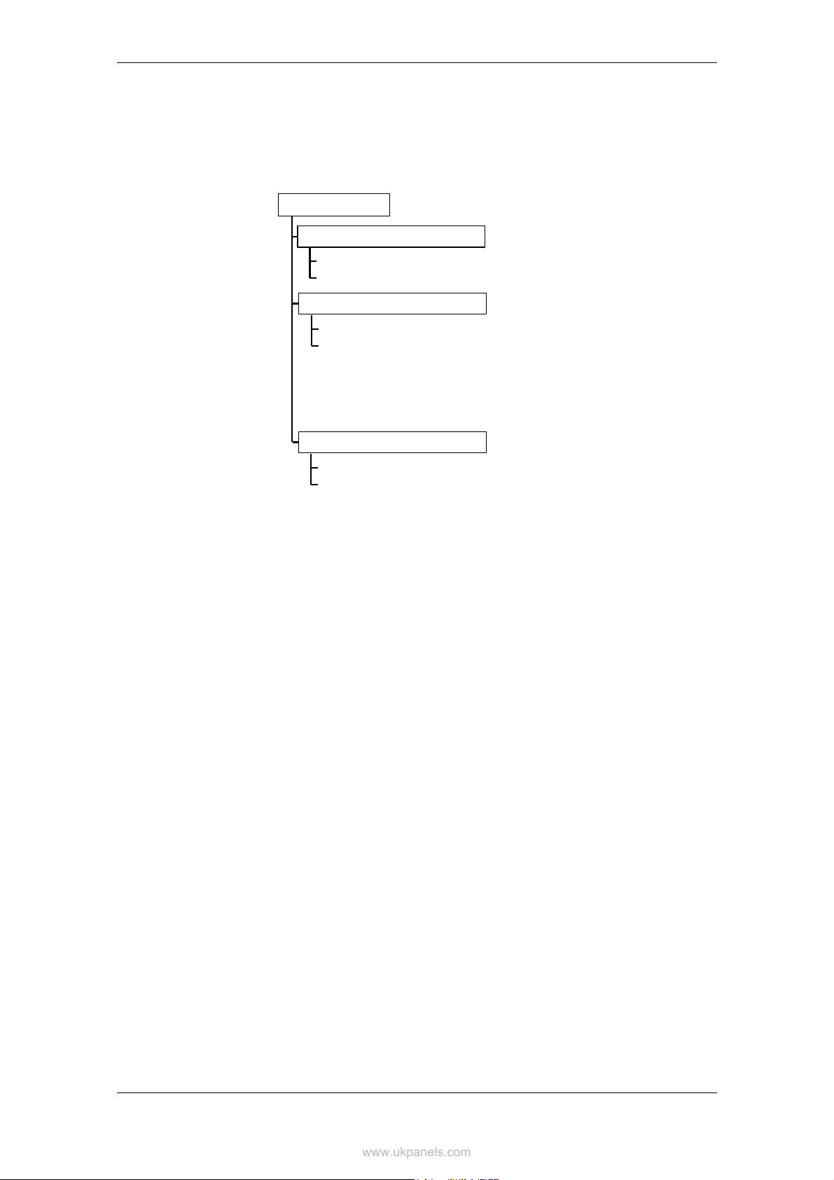
14.3 Testing
www.ukpanels.com
Service Commands
The Test Menu allows you to test Detection Zones (detectors and
manual call-points), Outputs plus Output Controls.
Test
Detection Zone Test (EN54)
Enter Test Mode
Leave Test Mode
Output Test
Manual Test ON
Manual Test OFF
Fire Alarm Devices
Fire Alarm Routing Equipment
Fault Warning Routing Equipment
Other Outputs
Output Control
Automatic Control ON
Automatic Control OFF
Door Control Units
Low Location Light Units
Standard Control Units
All
Figure 14-2: Test Menu
Operator's Handbook, AutroSafe Interactive Fire Alarm System, Release 3, ASAFE-FO/FE Rev. E, 021105,
Autronica Fire and Security AS
Page 85

Service Commands
www.ukpanels.com
14.3.1 Testing Detection Zones
14.3.1.1 Indications on the Operator Panel
During testing, the Testing indicator on the Operator Panel will show a
yellow steady light. The panel’s display will always indicate that a test
is being performed (as shown in the example below). The zones in test
mode are also shown.
TEST
1 OFFICES
1:SHOW POINTS
Figure 14-2: Test - indications on the display
19:23
Total: 1
Total: 1
19:23
Operator's Handbook, AutroSafe Interactive Fire Alarm System, Release 3, ASAFE-FO/FE Rev. E, 021105,
Autronica Fire and Security AS
Page 86

14.3.1.2 Entering Test Mode
www.ukpanels.com
To be able to manually test points (detectors or manual call-points)
without automatic actioning of Fire Protection Equipment (FPE), Fire
Alarm Routing Equipment (FARE) or Fire Alarm Devices (FAD),
detection zones can be set in test mode (ENTER TEST MODE). If a
detection zone has been set to test mode, any point connected to this
zone can be tested (with, for example, test gas) without automatic
actioning (i..e. audible indication) from sounders, bells, etc.
In the SHOW STATUS menu (main menu selection 1), you can now
verify that a point you have tested (for example, a detector you have
tested with test gas) operates properly - without audible indication.
As shown on the example below, a message on a status line will
appear (Alarm test), indicating that the alarm signal has been sent
from the tested point (in this example, P2, optical detector).
Service Commands
SHOW STATUS
DETECTION ZONES IN TEST(points)
1 CANTEEN
Received: 10:16:26
POINT: TYPE: ALARM STATE:
P2 Optical Alarm test
FIRE ALARMS Total: 1
3 CANTEEN
Figure 14-3: Show zones in test/points
19:23
The zones in test mode will always appear on the display. From here,
you can also enter the SHOW STATUS menu directly.
In test mode, the automatic timeout (default 25 seconds in operation
mode / menu mode) is 20 times the default timeout (i.e. up to 500
seconds) provided that no alarms occur within the timeout period.
The procedure below describes how to set a detection zone in test
mode.
Step Actions to be taken Display Indication
To enter the Main Menu, press
1
!
Operator's Handbook, AutroSafe Interactive Fire Alarm System, Release 3, ASAFE-FO/FE Rev. E, 021105,
Autronica Fire and Security AS
Page 87
MENU
1 SHOW STATUS
2 DISABLE
3 ENABLE
4 SYSTEM
5 SERVICE
19:23
Total: 3

Service Commands
www.ukpanels.com
Step Actions to be taken Display Indication
To select SERVICE, press 5.
2
To select TEST, press 1.
3
To select DETECTION ZONE TEST, press 1.
4
SERVICE
SERVICE
1 TEST
1 TEST
2 LOG
2 LOG
3 LOOP COMMANDS
3 LOOP COMMANDS
4 OIL&GAS INHIBIT
4 OIL&GAS INHIBIT
SERVICE
SERVICE
TEST
TEST
1 DETECTION ZONE TEST (EN 54)
1 DETECTION ZONE TEST (EN 54)
2 OUTPUT TEST
2 OUTPUT TEST
3 OUTPUT CONTROL
3 OUTPUT CONTROL
SERVICE
SERVICE
DZ TEST
DZ TEST
1 ENTER TEST MODE
1 ENTER TEST MODE
2 LEAVE TEST MODE
2 LEAVE TEST MODE
19:23
19:23
19:23
19:23
19:23
19:23
To ENTER TEST MODE, press 1.
5
Use the keyboard to enter text into the input box
6
-
OR ,- as shown in this example:
To select a Zone Name, press
then scroll downwards by pressing
9
YZ
or move up again by pressing
6
PQR
SERVICE
SERVICE
ENTER TEST MODE DZ
ENTER TEST MODE DZ
Zone Name:
Zone Name:
CANTEEN
CANTEEN
KITCHEN
KITCHEN
OFFICES
OFFICES
WORKSHOP
WORKSHOP
SERVICE
SERVICE
ENTER TEST MODE DZ
ENTER TEST MODE DZ
Zone Name:
Zone Name:
CANTEEN
CANTEEN
KITCHEN
KITCHEN
OFFICES
OFFICES
WORKSHOP
WORKSHOP
19:23
19:23
19:23
19:23
Operator's Handbook, AutroSafe Interactive Fire Alarm System, Release 3, ASAFE-FO/FE Rev. E, 021105,
Autronica Fire and Security AS
Page 88

Service Commands
www.ukpanels.com
Step Actions to be taken Display Indication
To enter Test Mode for the selected zone (in this
7
example CANTEEN is chosen), press twice on
SERVICE
SERVICE
DZ TEST
DZ TEST
1 ENTER TEST MODE
1 ENTER TEST MODE
2 LEAVE TEST MODE
2 LEAVE TEST MODE
14.3.1.3 Leaving Test Mode
The procedure below describes how to leave test mode for a selected
zone (LEAVE TEST MODE).
Step Actions to be taken Display Indication
To enter the Main Menu, press
1
!
MENU
1 SHOW STATUS
2 DISABLE
3 ENABLE
4 SYSTEM
5 SERVICE
19:23
Total: 3
19:23
19:23
To select SERVICE, press 5.
2
To select TEST, press 1.
3
SERVICE
SERVICE
1 TEST
1 TEST
2 LOG
2 LOG
3 LOOP COMMANDS
3 LOOP COMMANDS
4 OIL&GAS INHIBIT
4 OIL&GAS INHIBIT
SERVICE
SERVICE
TEST
TEST
1 DETECTION ZONE TEST (EN 54)
1 DETECTION ZONE TEST (EN 54)
2 OUTPUT TEST
2 OUTPUT TEST
3 OUTPUT CONTROL
3 OUTPUT CONTROL
19:23
19:23
19:23
19:23
Operator's Handbook, AutroSafe Interactive Fire Alarm System, Release 3, ASAFE-FO/FE Rev. E, 021105,
Autronica Fire and Security AS
Page 89

Service Commands
www.ukpanels.com
Step Actions to be taken Display Indication
To select DETECTION ZONE TEST, press 1.
4
To select LEAVE TEST MODE, press 2.
5
(Only Detection Zones in Test Mode will appear
in the display).
SERVICE
SERVICE
DZ TEST
DZ TEST
1 ENTER TEST MODE
1 ENTER TEST MODE
2 LEAVE TEST MODE
2 LEAVE TEST MODE
SERVICE
SERVICE
LEAVE TEST MODE DZ
LEAVE TEST MODE DZ
Zone Name:
Zone Name:
CANTEEN
CANTEEN
KITCHEN
KITCHEN
OFFICES
OFFICES
WORKSHOP
WORKSHOP
19:23
19:23
19:23
19:23
Use the keyboard to enter text into the input box
6
-
OR ,- as shown in this example:
To select a Zone Name, press
then scroll downwards by pressing
9
YZ
or move up again by pressing
6
PQR
To leave Test Mode for the selected zone (in this
7
example CANTEEN is chosen), press twice on
SERVICE
SERVICE
LEAVE TEST MODE DZ
LEAVE TEST MODE DZ
Zone Name:
Zone Name:
CANTEEN
CANTEEN
KITCHEN
KITCHEN
OFFICES
OFFICES
WORKSHOP
WORKSHOP
SERVICE
SERVICE
DZ TEST
DZ TEST
1 ENTER TEST MODE
1 ENTER TEST MODE
2 LEAVE TEST MODE
2 LEAVE TEST MODE
19:23
19:23
19:23
19:23
Operator's Handbook, AutroSafe Interactive Fire Alarm System, Release 3, ASAFE-FO/FE Rev. E, 021105,
Autronica Fire and Security AS
Page 90

14.3.2 Testing Outputs
www.ukpanels.com
14.3.2.1 Manual Test ON
The subsequent chapters describe how to test;
• Fire Alarm Devices (FAD)
• Fire Alarm Routing Equipment (FARE)
• Fire Warning Routing Equipment (FWRE)
• Other Outputs
Outputs activated by “Manual Test ON” will be kept active, i.e. reset
will not deactivate. An ongoing test can be terminated by use of the
Manual Test OFF menu.
14.3.2.2 Manual Test ON- Fire Alarm Devices (FAD)
This chapter describes how to test Fire Alarm Devices. The test
requires Access Level 3 (password restricted).
When the test is initiated, a test signal will be sent to all Fire Alarm
Devices within the selected Alarm Zone. The duration of the signal and
the interval between each signal are configurable (normally 1 second
ON and 30 seconds OFF).
The test signal is given the lowest priority. In the event of an alarm, the
alarm signal will thus override the test signal.
Service Commands
Step Actions to be taken Display Indication
To enter the Main Menu, press
1
!
To select SERVICE, press 5.
2
MENU
1 SHOW STATUS
2 DISABLE
3 ENABLE
4 SYSTEM
5 SERVICE
SERVICE
SERVICE
1 TEST
1 TEST
2 LOG
2 LOG
3 LOOP COMMANDS
3 LOOP COMMANDS
4 OIL&GAS INHIBIT
4 OIL&GAS INHIBIT
19:23
Total: 3
19:23
19:23
Operator's Handbook, AutroSafe Interactive Fire Alarm System, Release 3, ASAFE-FO/FE Rev. E, 021105,
Autronica Fire and Security AS
Page 91

Service Commands
www.ukpanels.com
Step Actions to be taken Display Indication
To select TEST, press 1.
3
To select OUTPUT TEST, press 2.
4
To select MANUAL TEST ON, press 1.
5
To select FIRE ALARM DEVICES, press 1.
6
SERVICE
SERVICE
TEST
TEST
1 DETECTION ZONE TEST (EN 54)
1 DETECTION ZONE TEST (EN 54)
2 OUTPUT TEST
2 OUTPUT TEST
3 OUTPUT CONTROL
3 OUTPUT CONTROL
SERVICE
SERVICE
OUTPUT TEST
OUTPUT TEST
1 MANUAL TEST ON
1 MANUAL TEST ON
2 MANUAL TEST OFF
2 MANUAL TEST OFF
SERVICE
SERVICE
MANUAL TEST ON
MANUAL TEST ON
1 FIRE ALARM DEVICES
1 FIRE ALARM DEVICES
2 FIRE PROTECTION EQUIP MENT
2 FIRE PROTECTION EQUIP MENT
3 FIRE WARNING ROUTING EQUIPMENT
3 FIRE WARNING ROUTING EQUIPMENT
4 OTHER OUTPUTS
4 OTHER OUTPUTS
SERVICE
SERVICE
MANUAL TES T ON>FAD
MANUAL TES T ON>FAD
Alarm Zone name:
Alarm Zone name:
ATTIC
ATTIC
GROUND FLOOR
GROUND FLOOR
HOUSE
HOUSE
19:23
19:23
19:23
19:23
19:23
19:23
19:23
19:23
Use the keyboard to enter text into the input box
7
-
OR ,- as shown in this example:
To select the Alarm Zone Name, press
then scroll downwards by pressing
9
YZ
or move up again by pressing
6
PQR
Operator's Handbook, AutroSafe Interactive Fire Alarm System, Release 3, ASAFE-FO/FE Rev. E, 021105,
Autronica Fire and Security AS
Page 92
SERVICE
SERVICE
MANUAL TES T ON>FAD
MANUAL TES T ON>FAD
Alarm Zone name:
Alarm Zone name:
ATTIC
ATTIC
GROUND FLOOR
GROUND FLOOR
HOUSE
HOUSE
19:23
19:23

Step Actions to be taken Display Indication
www.ukpanels.com
To accept the selected Alarm Zone and activate
8
the test, press twice on
SERVICE
SERVICE
MANUAL TEST ON
MANUAL TEST ON
1 FIRE ALARM DEVICES
1 FIRE ALARM DEVICES
2 FIRE PROTECTION EQUIP MENT
2 FIRE PROTECTION EQUIP MENT
3 FIRE WARNING ROUTING EQUIPMENT
3 FIRE WARNING ROUTING EQUIPMENT
4 OTHER OUTPUTS
4 OTHER OUTPUTS
A test signal will be sent to all Fire Alarm
Devices within the selected Alarm Zone.
14.3.2.3 Manual Test ON- Fire Alarm Routing Equipment (FARE)
The test is similar to the test for Fire Alarm Devices (FAD) and it
requires Access Level 3 (password restricted). For detailed
description, refer to 14.3.2.2.
When the test is initiated, a test signal will be sent to all Fire Alarm
Routing Equipment (FARE) within the Operation Zone (if there are
several Operation Zones, the signal will be sent to FARE in all
Operation Zones). The duration of the signal and the interval between
each signal are configurable (normally 1 second ON and 30 seconds
OFF).
The test signal is given the lowest priority. In the event of an alarm, the
alarm signal will thus override the test signal.
Service Commands
19:23
19:23
14.3.2.4 Manual Test ON- Fire Warning Routing Equipment (FWRE)
The test is similar to the test for Fire Alarm Devices (FAD) and it
requires Access Level 3 (password restricted). For detailed
description, refer to 14.3.2.2.
When the test is initiated, a test signal will be sent to all Fire Warning
Routing Equipment (FWRE) within the Operation Zone (if there are
several Operation Zones, the signal will be sent to FARE in all
Operation Zones). The duration of the signal and the interval between
each signal are configurable (normally 1 second ON and 30 seconds
OFF).
The test signal is given the lowest priority. In the event of an alarm, the
alarm signal will thus override the test signal.
Operator's Handbook, AutroSafe Interactive Fire Alarm System, Release 3, ASAFE-FO/FE Rev. E, 021105,
Autronica Fire and Security AS
Page 93

Service Commands
www.ukpanels.com
14.3.2.5 Manual Test ON - Other Outputs
This chapter describes how to test other outputs (outputs to Fire
Protection Equipment). The test requires Access Level 3 (password
restricted).
When the test is initiated, a test signal will be sent to the selected Fire
Protection Equipment.
NOTE:
Before this test is performed
(or other similar equipment) that are to be tested are
disconnected
measure the output on the Fire Protection Equipment that is to
be tested.
. During the test, use a measuring instrument to
Step Actions to be taken Display Indication
, make sure that all extinguishers
To enter the Main Menu, press
1
!
To select SERVICE, press 5.
2
To select TEST, press 1.
3
MENU
1 SHOW STATUS
2 DISABLE
3 ENABLE
4 SYSTEM
5 SERVICE
SERVICE
SERVICE
1 TEST
1 TEST
2 LOG
2 LOG
3 LOOP COMMANDS
3 LOOP COMMANDS
4 OIL&GAS INHIBIT
4 OIL&GAS INHIBIT
SERVICE
SERVICE
TEST
TEST
1 DETECTION ZONE TEST (EN 54)
1 DETECTION ZONE TEST (EN 54)
2 OUTPUT TEST
2 OUTPUT TEST
3 OUTPUT CONTROL
3 OUTPUT CONTROL
19:23
Total: 3
19:23
19:23
19:23
19:23
Operator's Handbook, AutroSafe Interactive Fire Alarm System, Release 3, ASAFE-FO/FE Rev. E, 021105,
Autronica Fire and Security AS
Page 94

Service Commands
www.ukpanels.com
Step Actions to be taken Display Indication
To select OUTPUT TEST, press 2.
4
To select MANUAL TEST ON, press 1.
5
SERVICE
SERVICE
OUTPUT TEST
OUTPUT TEST
1 MANUAL TEST ON
1 MANUAL TEST ON
2 MANUAL TEST OFF
2 MANUAL TEST OFF
SERVICE
SERVICE
MANUAL TEST ON
MANUAL TEST ON
1 FIRE ALARM DEVICES
1 FIRE ALARM DEVICES
2 FIRE PROTECTION EQUIP MENT
2 FIRE PROTECTION EQUIP MENT
3 FIRE WARNING ROUTING EQUIPMENT
3 FIRE WARNING ROUTING EQUIPMENT
4 OTHER OUTPUTS
4 OTHER OUTPUTS
19:23
19:23
19:23
19:23
To select OTHER OUTPUTS, press 4.
6
Use the keyboard to enter text into the input box
7
-
OR ,- as shown in this example:
To select an output, press
then scroll downwards by pressing
9
YZ
or move up again by pressing
6
PQR
To accept the selected output and activate the
8
test, press twice on
SERVICE
MANUAL TEST ON/OTHER OUTPUTS
Output name :
Digital Output 1
Digital Output 2
SERVICE
MANUAL TEST ON/OTHER OUTPUTS
Output name :
Digital Output 1
Digital Output 2
SERVICE
SERVICE
MANUAL TEST ON
MANUAL TEST ON
1 FIRE ALARM DEVICES
1 FIRE ALARM DEVICES
2 FIRE PROTECTION EQUIP MENT
2 FIRE PROTECTION EQUIP MENT
3 FIRE WARNING ROUTING EQUIPMENT
3 FIRE WARNING ROUTING EQUIPMENT
4 OTHER OUTPUTS
4 OTHER OUTPUTS
19:23
19:23
19:23
19:23
A test signal will be sent to the selected Fire
Protection Equipment.
Operator's Handbook, AutroSafe Interactive Fire Alarm System, Release 3, ASAFE-FO/FE Rev. E, 021105,
Autronica Fire and Security AS
Page 95

Service Commands
www.ukpanels.com
14.3.2.6 Manual Test OFF
The subsequent chapters describe how to terminate an ongoing test
for
• Fire Alarm Devices (FAD)
• Fire Alarm Routing Equipment (FARE)
• Fire Warning Routing Equipment (FWRE)
• Other Outputs
14.3.2.7 Manual Test OFF- Fire Alarm Devices (FAD)
This chapter describes how to terminate an ongoing test for Fire Alarm
Devices.
Step Actions to be taken Display Indication
To enter the Main Menu, press
1
!
To select SERVICE, press 5.
2
To select TEST, press 1.
3
MENU
1 SHOW STATUS
2 DISABLE
3 ENABLE
4 SYSTEM
5 SERVICE
SERVICE
SERVICE
1 TEST
1 TEST
2 LOG
2 LOG
3 LOOP COMMANDS
3 LOOP COMMANDS
4 OIL&GAS INHIBIT
4 OIL&GAS INHIBIT
SERVICE
SERVICE
TEST
TEST
1 DETECTION ZONE TEST (EN 54)
1 DETECTION ZONE TEST (EN 54)
2 OUTPUT TEST
2 OUTPUT TEST
3 OUTPUT CONTROL
3 OUTPUT CONTROL
19:23
Total: 3
19:23
19:23
19:23
19:23
Operator's Handbook, AutroSafe Interactive Fire Alarm System, Release 3, ASAFE-FO/FE Rev. E, 021105,
Autronica Fire and Security AS
Page 96

Service Commands
www.ukpanels.com
Step Actions to be taken Display Indication
To select OUTPUT TEST, press 2.
4
To select MANUAL TEST OFF, press 2.
5
To select FIRE ALARM DEVICES, press 1.
6
SERVICE
SERVICE
OUTPUT TEST
OUTPUT TEST
1 MANUAL TEST ON
1 MANUAL TEST ON
2 MANUAL TEST OFF
2 MANUAL TEST OFF
SERVICE
SERVICE
MANUAL TEST OFF
MANUAL TEST OFF
1 FIRE ALARM DEVICES
1 FIRE ALARM DEVICES
2 FIRE PROTECTION EQUIP MENT
2 FIRE PROTECTION EQUIP MENT
3 FIRE WARNING ROUTING EQUIPMENT
3 FIRE WARNING ROUTING EQUIPMENT
4 OTHER OUTPUTS
4 OTHER OUTPUTS
SERVICE
SERVICE
MANUAL TEST OFF>FAD
MANUAL TEST OFF>FAD
Alarm Zone name:
Alarm Zone name:
19:23
19:23
19:23
19:23
19:23
19:23
Use the keyboard to enter text into the input box
7
-
OR ,- as shown in this example:
To select the Alarm Zone Name, press
then scroll downwards by pressing
9
YZ
or move up again by pressing
6
PQR
To accept the selected Alarm Zone and
8
terminate the test, press
ATTIC
ATTIC
GROUND FLOOR
GROUND FLOOR
HOUSE
HOUSE
SERVICE
SERVICE
MANUAL TEST OFF>FAD
MANUAL TEST OFF>FAD
Alarm Zone name:
Alarm Zone name:
ATTIC
ATTIC
GROUND FLOOR
GROUND FLOOR
HOUSE
HOUSE
SERVICE
SERVICE
MANUAL TEST OFF
MANUAL TEST OFF
1 FIRE ALARM DEVICES
1 FIRE ALARM DEVICES
2 FIRE PROTECTION EQUIP MENT
2 FIRE PROTECTION EQUIP MENT
3 FIRE WARNING ROUTING EQUIPMENT
3 FIRE WARNING ROUTING EQUIPMENT
4 OTHER OUTPUTS
4 OTHER OUTPUTS
19:23
19:23
19:23
19:23
Operator's Handbook, AutroSafe Interactive Fire Alarm System, Release 3, ASAFE-FO/FE Rev. E, 021105,
Autronica Fire and Security AS
Page 97

Service Commands
www.ukpanels.com
14.3.2.8 Manual Test OFF - Fire Alarm Routing Equipment (FARE)
The procedure to terminate an ongoing test for Fire Alarm Routing
Equipment is similar to the procedure for Fire Alarm Devices. For
detailed description, refer to 14.3.2.7.
14.3.2.9 Manual Test OFF - Fire Warning Routing Equipment (FWRE)
The procedure to terminate an ongoing test for Fire Warning Routing
Equipment is similar to the procedure for Fire Alarm Devices. For
detailed description, refer to 14.3.2.7.
14.3.2.10 Manual Test OFF – Other Outputs
The procedure to terminate an ongoing test for other outputs is similar
to the procedure for Fire Alarm Devices. For detailed description, refer
to 14.3.2.7.
NOTE: When the test is terminated, make sure that all
extinguishers or other similar equipment are properly
connected.
Operator's Handbook, AutroSafe Interactive Fire Alarm System, Release 3, ASAFE-FO/FE Rev. E, 021105,
Autronica Fire and Security AS
Page 98
 Loading...