

116-P-ASAFE-COMMISS/EGB Rev.F, 2014-04-01, Autronica Fire And Security AS
Commissioning Handbook
AutroSafe Interactive Fire Detection System
Release 4
COPYRIGHT ©
This publication, or parts thereof, may
not be reproduced in any form, by any
method, for any purpose.
Autronica Fire and Security AS and its
subsidiaries assume no responsibility
for any errors that may appear in the
publication, or for damages arising
from the information in it. No
information in this publication should
be regarded as a warranty made by
Autronica Fire and Security AS. The
information in this publication may be
updated without notice.
Product names mentioned in this
publication may be trademarks. They
are used only for identification.
Commissioning Handbook, AutroSafe Interactive Fire Detection System, 116-P-ASAFE-COMMISS/EGB Rev.F, 2014-04-01, Autronica Fire and Security
E-1676
This product contains static-sensitive devices . Av oi d an y electrosta tic disc har ge.
The WEEE Directive
When the marking belo w is shown on the
product and/or its liter ature, it means t hat
the product should n ot be disposed with
other household wastes at the en d of its
life cycle. During waste treatment,
disposal and collection, please separate
the product from other types of wastes
and recycle it responsi bly to promote the
sustainable reuse of material resources.
This product should not be mixed with
other commercial wastes for disposal.

Introduction
Table of Contents
1. Introduction ...................................................................... 5
1.1 About the Handbook .......................................................................... 5
1.2 The Reader ....................................................................................... 5
1.3 Reference Documentation................................................................. 6
2. Quick Reference Guide ................................................... 7
2.1 Initial Commissioning ........................................................................ 7
2.2 Upgrading System Software and Configuration ................................ 7
3. Verifying the Loops ......................................................... 8
3.1 AS-2000 Loop Diagnostic Tool ......................................................... 8
3.2 Verification Procedure ....................................................................... 8
4. Consistency Check of Configur ati on Da t a ..................... 9
4.1 Introduction ........................................................................................ 9
4.2 Parameters Used for the Consistency Check ................................... 9
4.3 Importing Loop Data from the AS-2000 Tool .................................... 10
4.4 Consistency Check Using the AS-2000 / Config Mismatch Tool ..... 10
4.5 Generating Configuration Files ......................................................... 10
5. Power Commissioning .................................................... 11
5.1 Addressing Power Boards on the AutroFieldBus .............................. 11
5.1.1 Switch Settings on Power Board BSF-400 ............................. 11
5.1.2 Location of Switches ............................................................... 11
5.1.3 AutroFieldBus Addresses ....................................................... 13
5.1.4 Power Board Configuration Switches ..................................... 14
5.2 Calibration Procedure - Power Unit BPS-410 ................................... 15
6. Addressing Panels .......................................................... 16
6.1 Definitions .......................................................................................... 16
6.1.1 Network ID .............................................................................. 16
6.1.2 Panel ID .................................................................................. 16
6.2 Location of Switches ......................................................................... 17
6.3 Assigning Network IDs ...................................................................... 18
6.4 Assigning Panel IDs .......................................................................... 19
7. Verifying the System Bef ore Startup .............................. 21
8. Startup Procedure ........................................................... 22
8.1 Applying Power to the System .......................................................... 22
8.2 IP Number Structure .......................................................................... 24
8.3 Assigning IP Adresses ...................................................................... 24
8.3.1 Automatic Addressing Mode ................................................... 25
8.3.2 Manual Addressing Mode ....................................................... 27

Introduction
Commissioning Handbook, AutroSafe Interactive Fire Detection System, Release 4, 116-P-ASAFE-COMMISS/EGB Rev.F, 2014-04-01,
Autronica Fire and Security AS
Page 4
8.3.3 Configuration Missing.............................................................. 28
8.4 Configuration File .............................................................................. 29
8.4.1 Name, Format and Extension ................................................. 29
8.4.2 Copying the Zip File to a USB Stick ........................................ 29
8.5 Uploading Configuration Files to the System .................................... 30
8.6 Configuration Mismatch ..................................................................... 33
8.7 Entering Required Access Levels ..................................................... 34
9. Verifying the System after an Upload ............................. 36
9.1 General System Verification Procedure ............................................ 36
9.2 Verifying Detection Loops During Normal Operation ........................ 37
10. Upgrading the System ..................................................... 38
10.1 Introduction ........................................................................................ 38
10.2 Upgrading During Normal Operation (SW/Config) ............................ 38
10.2.1 Introduction ............................................................................. 38
10.2.2 Upgrading Software During Normal Operation ....................... 39
10.2.3 Upgrading Configuration During Normal Operation ................ 39
10.3 Upgrading when Panels are Added/Removed .................................. 40
10.4 Upgrading if IP Addresses are to be Changed.................................. 40
10.5 Upgrading a Single Panel.................................................................. 40
10.6 Upgrading by Remote Access to a Web site..................................... 41
10.7 Upgrading Software Version 4.0.1 to 4.1.1 ....................................... 42
10.7.1 General ................................................................................... 42
10.7.2 Preparing a System in Normal Operation ............................... 42
10.7.3 Preparing a System in System Fault Condition ...................... 43
10.8 Upgrading Software Version 4.0.1 or 4.1.1 to 4.3.1 .......................... 44
10.8.1 Example 1: Upgrading all Panels from SW Version 4.0.1
or 4.1.1 to 4.3.1 ...................................................................... 44
10.8.2 Example 2: Adding a BS-420/BS-430 panel with SW
Version 4.1.1 to a System Running on SW Version 4.3.1 ......
44
10.8.3 Example 3: Adding a BC-420 Controller with SW Version
4.1.1 to a System Running on SW Version 4.3.1 ................... 44
10.8.4 Example 4: Adding a Panel with SW Version 4.3.1 to a
System Running on SW Version 4.1.1.................................... 45
11. Startup Procedure for a Dua l S afe ty System ................. 46
11.1 Introduction ........................................................................................ 46
11.2 Guidelines – Startup Proce dur e ........................................................ 47
12. Fault Messages duri ng Uploading .................................. 49
12.1 Introduction ........................................................................................ 49
12.2 Invalid File on USB Stick ................................................................... 49
12.3 Data Transmission Timeout .............................................................. 49
12.4 Corrupt File ........................................................................................ 49
12.5 Fail to Unpack Files ........................................................................... 50
Introduction
Commissioning Handbook, AutroSafe Interactive Fire Detection System, Release 4, 116-P-ASAFE-COMMISS/EGB Rev.F, 2014-04-01,
Autronica Fire and Security AS
Page 5
1. Introduction
E-1676
This product contains static-sensitive devices .
Always use an antistatic wrist strap / ground bracelet to avoid any
electrostatic discharge.
1.1 About the Handbook
This handbook is intended to provide all necessary information for the
commissioning of the AutroSafe Interactive Fire Detection System,
Release 4.
The handbook covers the commissioning of a standalone system (Fire
Alarm Control Panel), as well as the commissioning of a distributed
system with several system units, operating on Autronica’s local area
network; AutroNet, including:
Power Boards in Power Cabinet BP-405 and
Power Unit BPS-405/BPS-410 (AutroFieldBus addressing)
Fire Alarm Control Panel BS-420
Controller BC-420 / BC-440
Operating Panel BS-430
Repeater Panel BU-BV-420
1.2 The Reader
The handbook is intended to be used by Autronica Fire and Security
trained service and technical personnel who are responsible for the
installation of the AutroSafe Interactive Fire Detection System,
Release 4.

Introduction
Commissioning Handbook, AutroSafe Interactive Fire Detection System, Release 4, 116-P-ASAFE-COMMISS/EGB Rev.F, 2014-04-01,
Autronica Fire and Security AS
Page 6
1.3 Reference Documentation
The table below shows an overview of the technical marketing
documentation for AutroSafe Interactive Fire Detection System,
Release 4.
Document Name
Part number
File name
System Description
116-P-ASAFE-SYSTEMD/EGB
asafesystemd_egb
Installation Handbook
116-P-ASAFE-INSTALL/DGB
asafeinstall_dgb
Commissioning Handbook
116-P-ASAFE-COMMISS/EGB
asafecommiss_egb
User Guide, Remote Access
116-P-ASAFE-REMOTEAC/EGB
asaferemoteac_egb
Connecting Loop Units
116-P-CONNECTLOOPUNIT/DGB
connectloopunit_dgb
Operator’s Handbook
116-P-ASAFE-OPERATE/FGB
asafeoperate_fgb
User Guide
116-P-ASAFE-USERGUI/LGB
asafeusergui_lgb
Wall Chart
116-P-ASAFE-WALLCHA/LGB
asafewallcha_lgb
Menu Structure
116-P-ASAFE-MENUSTR/MGB
asafemenustr_mgb
Datasheet; Fire Alarm Control Panel BS-420
116-P-BS420/CGB
bs420_cgb
Datasheet; Operator Panel BS-430
116-P-BS430/CGB
bs430_cgb
Datasheet; Repeater Panel BU-BV-420
116-P-BUBV420/CGB
bubv420_cgb
Datasheet; Fire Brigade Loop Panel BU-110
116-P-BU110/CGB
bu110_cgb
Datasheet; Information Loop Panel BV-110
116-P-BV110/CGB
bv110_cgb
Datasheet; Controller BC-420
116-P-BC420/CGB
bc420_cgb
Datasheet; Controller Unit Rack BC-440
116-P-BC440/CGB
bc440_cgb
Datasheet; Power Cabinet BP-405
116-P-BP405/CGB
bp405_cgb
Datasheet; Power Unit BPS-405
116-P-BPS405/CGB
bps405_cgb
Datasheet; Power Unit BPS-410
116-P-BPS410/CGB
bps410_cgb
Datasheet; AutroKeeper BN -180
116-P-BN180/CGB
bn180_cgb

Quick Reference Guide
Commissioning Handbook, AutroSafe Interactive Fire Detection System, Release 4, 116-P-ASAFE-COMMISS/EGB Rev.F, 2014-04-01,
Autronica Fire and Security AS
Page 7
2. Quick Reference Guide
This quick reference guide outlines all the necessary steps to
successfully commission the AutroSafe Interactive Fire Detection
System the very first time, assuming that the system software is
already uploaded to the system, and no configuration files have been
uploaded.
Configuration upgrade and system software upgrade are described in
a separate chapter (Chapter 10).
2.1 Initial Commissioning
Step Action Chapter
1
Verify the detection loops by means of the AS-2000 tool.
Chapter 3
2
Perform a consistency check of the configuration data
using the results from the AS-2000 verification and the data
that has been configured by means of the AutroSafe
Configuration Tool.
Chapter 4
3
Assign an AutroFieldBus address to each Power Board
BSF-400 (rotary switches) / AutroFieldBus unit.
Chapter 5
4
Assign a Network ID to each panel by means of rotary
switches (on BSA-400).
Chapter 6.3
5
Assign a Panel ID to each panel by means of switches (dipswitches and rotary switches on BSA-400).
Chapter 6.3
6
Verify the system before startup
Chapter 7
7
Apply power to the system
Chapter 8.1
8
Assign an IP Address to each panel
Chapter 8.3
9
Upload configuration data to all panels from one central
point (a panel).
Chapter 8.5
10
Verify the system after an upload
Chapter 9
2.2 Upgrading System Software and Configuration
For information regarding configuration upgrade and system software
upgrade, refer to Chapter 10.

Verifying the Loops
Commissioning Handbook, AutroSafe Interactive Fire Detection System, Release 4, 116-P-ASAFE-COMMISS/EGB Rev.F, 2014-04-01,
Autronica Fire and Security AS
Page 8
3. Verifying the Loops
3.1 AS-2000 Loop Diagnostic Tool
All loops should be verified with the AS-2000 Loop Diagnostic Tool
before startup. Although this is presumably already done at an earlier
stage (shortly after the installation), it is recommended that all loops
are verified once again in case minor changes have been done. By
doing this, you will eliminate possible pr ob lems which could occur
during the startup procedure and upgrading of configuration data.
The AS-2000 allows you to find all points connected to the selected
loop driver, and present them graphically.
AS-2000 can be connected directly to an AutroSafe
operating panel, or directly to a detection loop by means of an
external interface unit, WAS-2000.
3.2 Verification Procedure
Pressing the START button in the Topology window (AS-2000) tells
AS-2000 to find all points connected to the selected loop driver, and
present them graphically in a correct electrical sequence. Points will
be presented with unique symbols for each type of Loop Unit, and wi th
important information such as Production Number (PN), and the Loop
Sequence Index (LSI). In case of illegal topologies, like multiple
branch-offs and loop breaks, these will be presented with selfexplaining symbols.
Use the AS-2000 to;
register all loop units on each loop, including:
− the Loop Unit type
(detector type, manual call point, electronic sounder, I/O unit)
− Loop Sequence Indexes LSI
(order/location)
register all branch offs and loop break positions
locate any breaks on the loop wire (both positive and negative
wires)
measure the loops’ total resistance, current consumption and
voltage drop
earth fault
You will find detailed information on the installation and use of
AS-2000 in the User Guide, AS-2000 Loop Diagnostic Tool.

Consistency Check
of Configuration Data
Commissioning Handbook, AutroSafe Interactive Fire Detection System, Release 4, 116-P-ASAFE-COMMISS/EGB Rev.F, 2014-04-01,
Autronica Fire and Security AS
Page 9
4. Consistency Check
of Configuration Data
4.1 Introduction
4.2 Parameters Used for the Consistency Check
The table below provides a description of two of the parameters that
are used for the consistency check. These parameters are shown in
the Topology View in AS-2000, as well as in the topology view in the
AutroSafe Configuration Tool.
Parameter
Abbreviation
Description
Illustration
Loop Unit
The loop unit
can be a
detector, a
manual call
point, a loop
sounder or an
I/O unit.
(Examples)
Heat detector (BD-200/300/500)
Optical smoke detector (BH-200/300/500)
MultiSensor detector (BH-220/320/520)
Manual callpoint (BF-200/300/500)
Electronic addressable sounder
(BBR-200)
Input / Output unit (BN-300, BN-310, BN-320 etc.)
Loop
Sequence
Index
LSI
A loop specific
index telling the
exact Loop Unit
order on the
loop
(sequencially
numbered).
A branch-off is
described by a
decimal
followed by a
sequencial
index.
NOTE:
To ensure a problem-
free upload of configuration data, always
perform a consistency check, using the results from the
AS-2000 verification and the data that has been configured by
means of the AutroSafe Configuration Tool.
(Example)

Consistency Check
of Configuration Data
Commissioning Handbook, AutroSafe Interactive Fire Detection System, Release 4, 116-P-ASAFE-COMMISS/EGB Rev.F, 2014-04-01,
Autronica Fire and Security AS
Page 10
4.3 Importing Loop Data from the AS-2000 Tool
The AutroSafe Configuration Tool features an Import command
allowing you to import loop data directly from the AS-2000 Loo p
Diagnostic tool. In this way, it is possible to ensure that the point types
and sequence indexes in the configuration will be identical to the real
loop. Tag Names and optional Detection Zones (DZs) will be assigned
to the points during import.
For further information, refer to the Help System for AutroSafe
Configuration Tool and the User Guide for the AS-2000 Loop
Diagnostic Tool.
4.4 Consistency Check Using the
AS-2000 / Config Mismatch Tool
4.5 Generating Configuration Files
System configuration is done from a computer by the means of the
AutroSafe Configuration Tool. This tool allows you to generate
configuration files, which then can be uploaded to target after the
system has been verified.
The AutroSafe Configuration Tool allows you to do a
consistency check of configuration data by means of a menu
called AS-2000 / Config Mismatch Tool (in the Tool menu).
This feature allows you to easily compare the actual
configuration data downloaded from a detection loop and
imported to the AutroSafe Configuration Tool (using
the AS-2000) with the configuratio n d ata you have entered in
the AutroSafe Configuration Tool.

Power Commissioning
Commissioning Handbook, AutroSafe Interactive Fire Detection System, Release 4, 116-P-ASAFE-COMMISS/EGB Rev.F, 2014-04-01,
Autronica Fire and Security AS
Page 11
5. Power Commissioning
5.1 Addressing Power Boards on the AutroFieldBus
5.1.1 Switch Settings on Power Board BSF-400
The board is configured by means of two switches:
Rotary switches X10 and X11 - AutroFieldBus address switch.
Each Power Board is given a unique address.
Dipswitch S5/S6 – configuration (refer to dipswitch table, chapter
5.1.4)
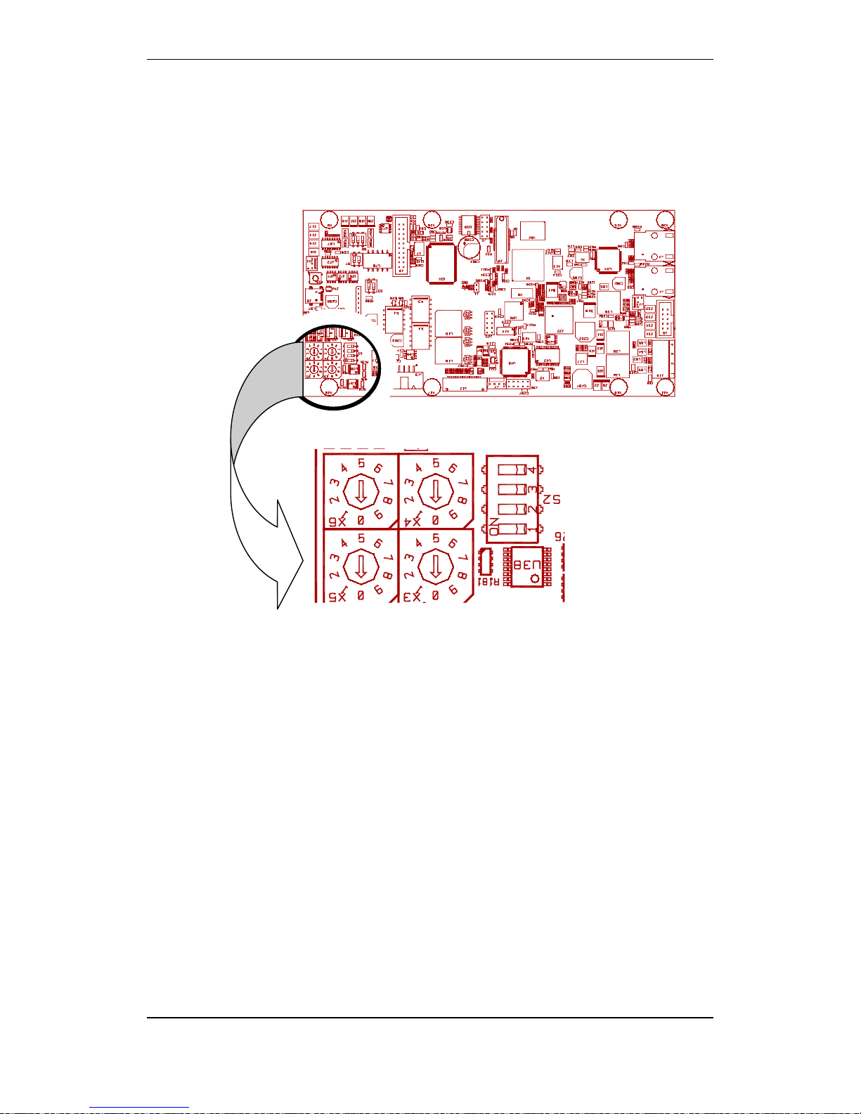
5.1.2 Location of Switches
The location of the dipswitch S5 and S6, plus the rotary switches X10
and X11 are shown on the drawing.

Power Commissioning
Commissioning Handbook, AutroSafe Interactive Fire Detection System, Release 4, 116-P-ASAFE-COMMISS/EGB Rev.F, 2014-04-01,
Autronica Fire and Security AS
Page 12
1
2
3
AFB A
AFB A"
AFB CT A
4
5
6
AFB Earth Fault Sense
AFB B
AFB B"
7
8
AFB CT B
AFB Earth Fault Sense
J2
1
6
1
2
3
A
A
R
4
5
6
F
F
F
F1
F2
J19
S1 Reset
High Low
8
7
6
5
4
3
2
1
J24
J23
J22
0V
C2
J21
F2AL
F3 B1
F2AL
F4 B2
F2AL
F5 C1
F2AL
F6 C2
A
1
2
3
Earth Fa
Battery
AFB pre
4
5
6
Battery
61
S6
ON
OFF
15
5
4
3
2
1
Therm.+
Therm.PSF
-V
Vcon
+
-
BATT
J20
J17
F7 Battery
F8 Charger
1
Charger +24V
J18
+
0V
+
C1
0V
+
B2
0V
+
B1
0V
+
A2
0V
+
A1
X11
X10
BP-410/01
BP-405/01
T10T5T10
T5
F7 F8
AH AH
AH AH
S5
AFB Earth Fault Off
AFB Earth Fault On
1
OFF
ON
2
OFF
ON
Dipswitch S6
AutroFieldBus
Address Switch
X10, X11
Dipswitch S5
S1 Reset button

Power Commissioning
Commissioning Handbook, AutroSafe Interactive Fire Detection System, Release 4, 116-P-ASAFE-COMMISS/EGB Rev.F, 2014-04-01,
Autronica Fire and Security AS
Page 13
5.1.3 AutroFieldBus Addresses
Each AutroFieldBus unit/Power Board BSF-400 on an AutroFieldBus
must be assigned a unique address by means of an rotary switch (see
previous page).
The drawing below shows the AutroFieldBus connections on the main
terminal block, list L1 mounted on a DIN rail inside the cabinet
(BS-420/BC-420). The first AutroFieldBus unit is connected to the
terminals L1.9 / L1.11 (AFB A). The last unit is connected to L1.3 /
L1.5 (AFB B).
CT (CenterTap) of transformer shall not be connected (terminal 3 and
11). Shield is connected to earth at one end only.
L1.3
L1.5
L1.7
L1.15
L1.9
L1.11
L1.13
Last AFB unit
First AFB unit
SA 400 with shielded AF cable
A maximum of 31 AutroFieldBus units can be connected to one
AutroFieldBus, giving the number range 01 to 31. The physical
addresses are set by means of the rotary switches on the board.
The illustration below shows an example of the system topology
window. 4 AutroFieldBus units are added to the AutroFieldBus
interface.
The sequence of the units in the topology window determines the
switch settings on each unit, i.e. the first unit (the uppermost unit in
the topology window) is to be given switch address 01, the next is to
be given switch address 02, and so on.
Note that the physical sequence of AutroFieldBus units on the
AutroFieldBus must not necessarily corres p ond to the s equence
shown in the topology window, however this is recommended.
Addressing AutroFieldBus units on the AutroFieldBus
Fire Alarm Control
Panel BS-420
BSA-400
BSF-400
BSD-321
BSF-400
AutroFieldBus
Switch
Address 01
BSF-400
Switch
Address 02
Switch
Address 03
Switch
Address 04
Always address 00
The first AutroFieldBus unit
Example: System topology window in
the AutroSafe Configuration Tool
Switch address 01
Switch address 02
Switch address 03
Switch address 04
Main terminal block, list L1
inside the BS-420/BC-420
AFB
AFB

Power Commissioning
Commissioning Handbook, AutroSafe Interactive Fire Detection System, Release 4, 116-P-ASAFE-COMMISS/EGB Rev.F, 2014-04-01,
Autronica Fire and Security AS
Page 14
5.1.4 Power Board Configuration Switches
The settings of the dipswitches are read during startup. If the switches
are changed for any reason, the changes will not take affect until the
Power Board is restarted (pressing the reset button S1 on the Power
Board).
Dipswitch table – S5
S5.1
S5.2
Function
OFF
OFF
AutroFieldBus earth fault OFF
ON
ON
AutroFieldBus earth fault ON
Dipswitch table – S6
Switch
Name
Comment
S6-1 Earth Fault
ON: Earth fault monitoring
activated
OFF: Earth fault monitoring
deactivated
S6-2 NA
Must always be set to OFF
(default).
S6-3 AutroFieldBus
ON: AutroFieldBus connected
OFF: AutroFieldBus not
connected
S6-4
NA
-
S6-5
Battery
ON: Battery connected
OFF: Battery not connected
S6-6
Power Unit Type
ON: BPS-405
OFF: BPS-410
Power Commissioning
Commissioning Handbook, AutroSafe Interactive Fire Detection System, Release 4, 116-P-ASAFE-COMMISS/EGB Rev.F, 2014-04-01,
Autronica Fire and Security AS
Page 15
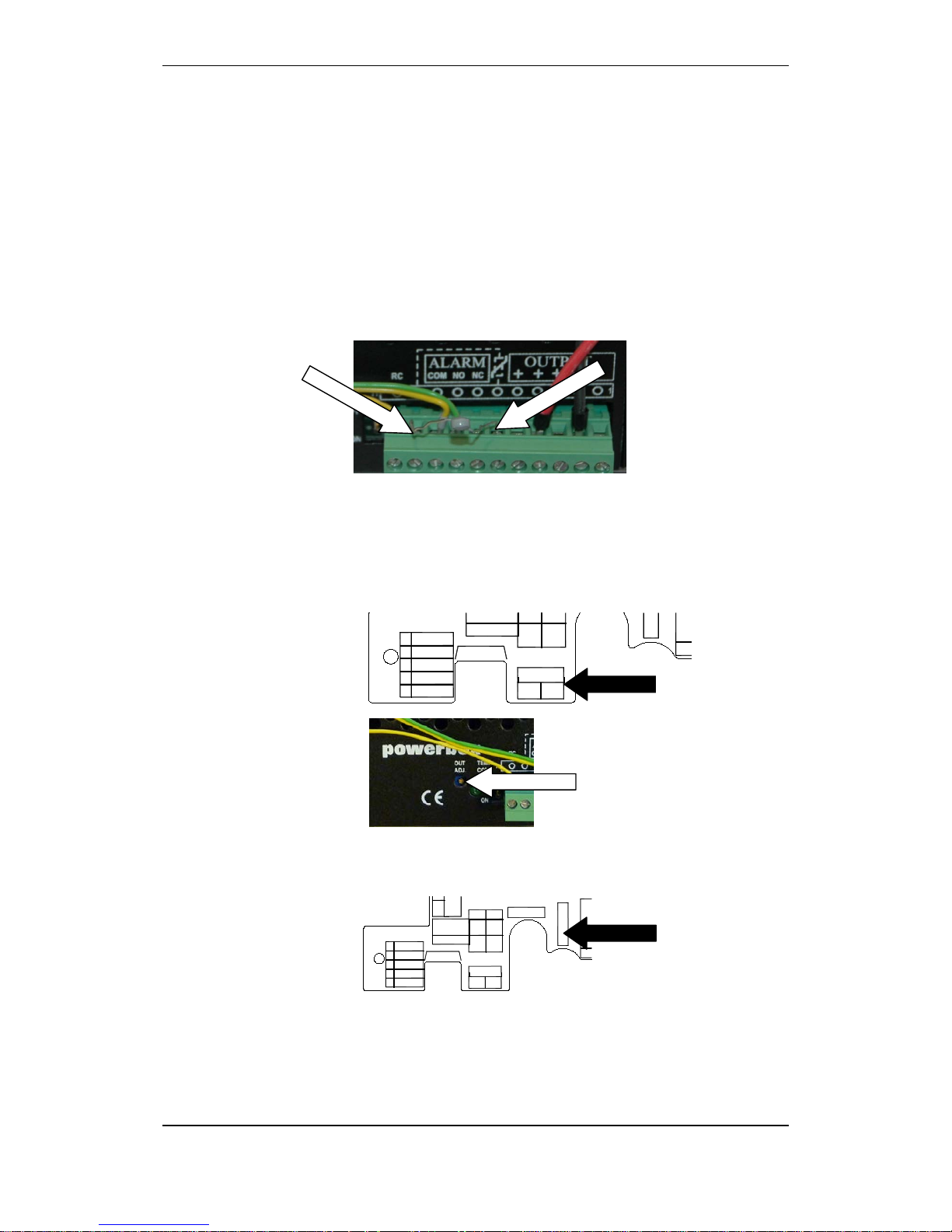
5.2 Calibration Procedure - Power Unit BPS-410
When using Power Unit BPS-410 (including a 24V/10A power supply),
a calibration procedure must be performed. This is necessary in order
to obtain a correct temperature compensated charging voltage to the
batteries. The procedure is as follows:
Before applying power to the system, the power supply’s
temperature sensor (thermistor delivered with the power unit) must
be temporarily replaced with a fixed 2,2k resistor (terminal point 2
and 6 from the left, marked with a stippled line from terminal point
2 to the thermistor symbol at point 6).
Apply power to the system by connecting the mains cable to the
mains socket or by switching the power ON from an external main
fuse box.
Measure the voltage on the BSF-400’s battery terminals (BATT +/-)
while adjusting the voltage with a small screw driver to 27,4V on
the power supply (OUT ADJ).
Disconnect mains power from the power supply and remove
charger fuse F8.
Remove the resistor and reinsert the thermistor.
Insert the charger fuse F8 and re-connect mains power to the
power supply.
15
5
4
3
2
1
Therm.+
Therm.PSF
-V
Vcon
+
-
BATT
J20
J17
arger
1
+24V
BP-405/01 T5 T5
AH AH
AH AH
0V
C2
15
5
4
3
2
1
Therm.+
Therm.PSF
-V
Vcon
+
-
BATT
J20
J17
F7 Battery
F8 Charger
1
Charger +24V
BP-410/01
BP-405/01
T10T5T10
T5
F7 F8
AH AH
AH AH
Measure
Adjust
Charger fuse F8
Addressing Panels
Commissioning Handbook, AutroSafe Interactive Fire Detection System, Release 4, 116-P-ASAFE-COMMISS/EGB Rev.F, 2014-04-01,
Autronica Fire and Security AS
Page 16
6. Addressing Panels
6.1 Definitions
6.1.1 Network ID
A panel’s Network ID indicates which system and unique configuration
a panel belongs to. All panels communicating on the same AutroNet
network must have the same Network ID, usually set to 01 (switch
setting; rotary switches X5 and X3).
The Network ID also determines the specific number series of the IP
Addresses (which are set during commissioning by operating the
AutroSafe menu).
6.1.2 Panel ID
Each panel in the system must be assigned a unique Panel ID (switch
setting; rotary switches X6 and X4, plus the settings of dip-switch S2).
For each different panel type (i.e. BS-420 or BU-420) the addressing
on the rotary switches always starts on 0-1.
The Configuration Tool generates a catalogue structure with the
following number series of Panel IDs for the different panel types.
(Note that the physical adressing on the rotary switches does not
follow the numbering series generated by the Configuration Tool).
Panel Panel IDs
Number Series
Panel IDs
Hexadecimal
values
BS-420
1-31
01-1F
BC-420
33-63
21–3F
BC-440
33-63
21–3F
BS-430
65-95
41-5F
BU-420
97-159
61-9F
BV-420
161-223
A1-DF
Addressing Panels
Commissioning Handbook, AutroSafe Interactive Fire Detection System, Release 4, 116-P-ASAFE-COMMISS/EGB Rev.F, 2014-04-01,
Autronica Fire and Security AS
Page 17
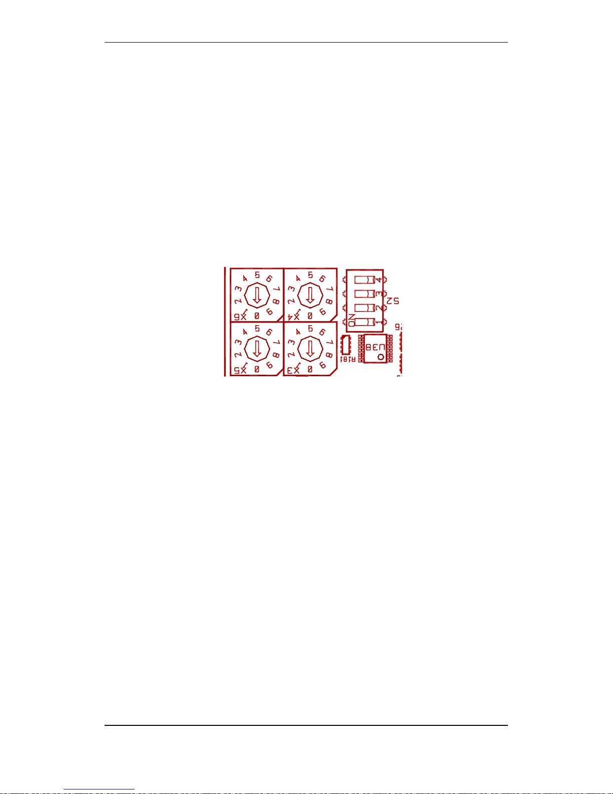
6.2 Location of Switches
The switches are located on the lower left hand side of the BSA-400
circuit board, easily access ible throu gh the hol e in the metal cover.
The BSA-400 circuit board
X3
X5
X6
X4
S2
Addressing Panels
Commissioning Handbook, AutroSafe Interactive Fire Detection System, Release 4, 116-P-ASAFE-COMMISS/EGB Rev.F, 2014-04-01,
Autronica Fire and Security AS
Page 18
6.3 Assigning Network IDs
The settings of the rotary switches X5 and X3 determine the panel’s
Network ID, i.e. which system and unique configuration the panel
belongs to.
All panels communicating on the same AutroNet network must have
the same Network ID, usually set to 01.
X5 is set to 0
X3 is set to 1
If there is a second network, this network can be set to 02, a third can
be set to 03, etc.
Switch X5 corresponds to the most significant digit in the address.
X3
X5

Addressing Panels
Commissioning Handbook, AutroSafe Interactive Fire Detection System, Release 4, 116-P-ASAFE-COMMISS/EGB Rev.F, 2014-04-01,
Autronica Fire and Security AS
Page 19
6.4 Assigning Panel IDs
Each panel in the system must be assigned a unique Panel ID (switch
setting; rotary switches X6 and X4, plus the settings of dip-switch S2).
For each different panel type (i.e. BS-420 or BU-420) the addressing
on the rotary switches always starts on 0-1.
Note that a standalone Fire Alarm Control Panel BS-420 always has
Panel ID=00.
Switch X6 corresponds to the most significant digit in the address.
Note that the correct switch settings for the panel type in question is
preset at the factory (dipswitch S2) - except for the BU-BV-420 panel,
as this panel can be defined both as a Information Panel and Fire
Brigade Panel.
The following table deals with the Panel IDs when several panels
communicate on the AutroNet (local area network).
Panel
Panel ID
Panel ID
Hex.
values Rotary
switch X6
Rotary
switch X4
Panel Type
Dip-switch S2
0=OFF, 1=ON
Switch 1 2 3 4
BS-420
1-31
01-1F
0-3
0-9
0 0 0 0
BC-420
33-63
21–3F
0-3
0-9
1 0 0 0
BC-440
33-63
21–3F
0-3
0-9
1 0 0 1
BS-430
65-95
41-5F
0-3
0-9
0 1 0 0
BU-420
97-159
61-9F
0-6
0-9
1 1 0 0
BV-420
161-223
A1-DF
0-6
0-9
1 0 1 0
X6
X4
S2

Addressing Panels
Commissioning Handbook, AutroSafe Interactive Fire Detection System, Release 4, 116-P-ASAFE-COMMISS/EGB Rev.F, 2014-04-01,
Autronica Fire and Security AS
Page 20
Example:
A network configuration consists of two BS-420 panels, one BS-430
panel and one BU-BV-420 panel (a BU-BV-420 panel defined as a
Fire Brigade Panel).
In this example, the following addressing applies:
Panel
Panel ID
Rotary
switch X6
Rotary
switch X4
Panel Type
Dip-switch S2
0=OFF, 1=ON
Switch 1 2 3 4
BS-420
1 0 1
0 0 0 0
BS-420
2 0 2
0 0 0 0
BS-430
65 0 1
0 1 0 0
BU-BV-420
97 0 1
1 1 0 0

Verifying the System Before Startup
Commissioning Handbook, AutroSafe Interactive Fire Detection System, Release 4, 116-P-ASAFE-COMMISS/EGB Rev.F, 2014-04-01,
Autronica Fire and Security AS
Page 21
7. Verifying the System Before
Startup
Before verifying the system, all parts in all system units must be
installed and properly connected, and all panels and AutroFieldBus
units must be addressed correctly.
Installation, cabling and connections
Verify all internal cabling in all system units (all panels)
Verify that all IO modules in the Fire Alarm Control Panel and
Controller are installed in the cabinet
Verify all external connections in the Fire Alarm Control Panel and
Controller (to detector loops, other input / output connections)
Verify all network connections
Addressing
Verify that all AutroFieldBus units (Power Boards BSF-400) are
addressed correctly
Verify that all panels are assigned correct Panel IDs
Verfiy that all panels are assigned Network IDs
Check power for correct mains voltage

Startup Procedure
Commissioning Handbook, AutroSafe Interactive Fire Detection System, Release 4, 116-P-ASAFE-COMMISS/EGB Rev.F, 2014-04-01,
Autronica Fire and Security AS
Page 22
8. Startup Procedure
When the AutroFieldBus units (Power Boards BSF-400, BSD-321 and
all panels) have been addressed, and the configuration files have
been generated by means of the AutroSafe Configuration Tool, power
is to be applied to the system.
The commissioning can take place from any Fire Alarm Control Panel
BS-420 or Operator Panel BS-430 in the system (freely selected
panel).
During uploading of configuration files (or system software), the
system may report possible faults. If such fault messages occur, the
panel in question should be rebooted (Service
Menu/Upgrade/Reboot). For detailed information on possible errors,
refer to chapter 12, Fault Messages during Uploading.
8.1 Applying Power to the System
Always connect the cables to the batteries first, then power up the
system by connecting the mains cable to a mains socket (230V/115V
AC) or by switching the power ON from an external main fuse box.
When power is applied to the system the very first time, an
initialization of the system will automatically take place.
Apply power to the system.
The display will show the following information (example):
Autrosafe software version 4.5.0
Config model 4.5
Market version: Land
Switch address 01-001
Searching for panels, found 2
BS-420 01.01: 4.3.1 Commiss. Star
BU-420 01.01: 4.3.1 Commiss. ??
Detecting network structure…
5. Update panel list
The system will automatically detect the network structure that is
used, either Star Topology or Ring Topology. If both topologies are
detected, the message: “Conflicting Network Structure” will appear,
and it will not be possible to proceed.

Startup Procedure
Commissioning Handbook, AutroSafe Interactive Fire Detection System, Release 4, 116-P-ASAFE-COMMISS/EGB Rev.F, 2014-04-01,
Autronica Fire and Security AS
Page 23
Autrosafe software version 4.5.0
Config model 4.5
Market version: Land
Switch address 01-001
Searching for panels, found 2 of 2
BS-420 01.01: 4.3.1 Commiss. Star
BU-420 01.01: 4.3.1 Commiss. Star
IP not set, select addressing mode:
1. Automatic 2. Manual
(Note that, to prepare the system for later reconfigurations or software
upgrades, a hardware reset must be performed. Refer to Upgrading
the System, chapter 10.)

Startup Procedure
Commissioning Handbook, AutroSafe Interactive Fire Detection System, Release 4, 116-P-ASAFE-COMMISS/EGB Rev.F, 2014-04-01,
Autronica Fire and Security AS
Page 24
8.2 IP Number Structure
Example:
172.16.101.21
172.17.101.117
172.16.101.21
8.3 Assigning IP Adresses
When the initialization is completed, the display will show the
following:
Autrosafe software version 4.5.0
Config model 4.5
Market version: Land
Switch address 01-001
Searching for panels, found 2 of 2
BS-420 01.01: 4.3.1 Commiss. Star
BU-420 01.01: 4.3.1 Commiss. Star
IP not set, select addressing mode:
1. Automatic 2. Manual
If Automatic Mode is selected, default IP Adresses will be assigned to
each panel. The number series which is used depends on the switch
settings for the panel’s Network ID.
Note:
Use automatic addressing mode if you are not absolutely sure how to
set IP addresses.
Panel ID (+20), unique ID assigned to each panel.
Network ID (+100), identifies the unique network the
panel belongs to.
Subnet ID, common number for all panels. 172.16.x.x
for primary and 172.16.x.x for secondary network.

Startup Procedure
Commissioning Handbook, AutroSafe Interactive Fire Detection System, Release 4, 116-P-ASAFE-COMMISS/EGB Rev.F, 2014-04-01,
Autronica Fire and Security AS
Page 25
8.3.1 Automatic Addressing Mode
Selecting Automatic Addres s ing Mode wi ll ass ign default IP
Addresses to all panels.
Autrosafe software version 4.5.0
Config model 4.5
Market version: Land
Switch address 01-001
Searching for panels, found 2 of 2
BS-420 01.01: 4.3.1 Commiss. Star
BU-420 01.01: 4.3.1 Commiss. Star
IP not set, select addressing mode:
1. Automatic 2. Manual
Press 1 to select Automatic Addressing.
Autrosafe software version 4.5.0
Config model 4.5
Market version: Land
Switch address 01-001
NETWORK ADDRESS: 172.16/172.17
BS-420 01.01: 101.21
BU-420 01.01: 101.117
Do you want to save or set manually?
1. Save 2. Set Address Manually
When the automatic addressing is completed, you can either save the
automatic addressing (proceed to next step), or set addresses
manually (refer to chapter 8.3.2, Manual Addressing Mode).

Startup Procedure
Commissioning Handbook, AutroSafe Interactive Fire Detection System, Release 4, 116-P-ASAFE-COMMISS/EGB Rev.F, 2014-04-01,
Autronica Fire and Security AS
Page 26
To save the addressing, press 1.
Autrosafe software version 4.5.0
Config model 4.5
Market version: Land
Switch address 01-001
Searching for panels, found 2 of 2
BS-420 01.01: 4.3.1 Commiss. Star
BU-420 01.01: 4.3.1 Commiss. Star
Config missing
Verify config on switch settings
3. Upgrade software 4. Upgrade config
6. Reboot panels
When the IP addressing is completed, proceed to chapter 8.5,
Uploading Configuration Files.

Startup Procedure
Commissioning Handbook, AutroSafe Interactive Fire Detection System, Release 4, 116-P-ASAFE-COMMISS/EGB Rev.F, 2014-04-01,
Autronica Fire and Security AS
Page 27
8.3.2 Manual Addressing Mode
If you have to take into consideration IP Addresses that are already
assigned to other existing components on the network, IP Addresses
can be set manually. In this way, you can freely select IP Addresses
within the given ranges of 3 different number series, each
representing a specific class (Class A, B or C).
Note that the standard IP version 4 addressing is applied. This means
that once a specific class is selected (A, B or C), only numbers within
the range of this class can be selected.
Class A: number series 1-127
Class B: number series 128-191
Class C: number series 192-223
Autrosafe software version 4.5.0
Config model 4.5
Market version: Land
Switch address 01-001
IP ADDRESS: 172.16/172.17
BS-420 01.01: 101.21
BU-420 01.01: 101.117
Please set the SUB A network address:
<10 . . . >
<11 . . . >
Set the network addresses
If necessary, press 1 to change host address
Press 2 to save the manual addressing
When the manual IP addressing is completed, proceed to chapter 8.5,
Uploading Configuration Files.

Startup Procedure
Commissioning Handbook, AutroSafe Interactive Fire Detection System, Release 4, 116-P-ASAFE-COMMISS/EGB Rev.F, 2014-04-01,
Autronica Fire and Security AS
Page 28
8.3.3 Configuration Missing
If no configuration has been uploaded to the system previously, the
message “Config Missing” will be shown.
Autrosafe software version 4.5.0
Config model 4.5
Market version: Land
Switch address 01-001
Searching for panels, found 2
BS-420 01.01: 4.3.1 Commiss. Star
BU-420 01.01: 4.3.1 Commiss. Star
Config missing
1. Import config from USB stick
2. Reboot all panels

Startup Procedure
Commissioning Handbook, AutroSafe Interactive Fire Detection System, Release 4, 116-P-ASAFE-COMMISS/EGB Rev.F, 2014-04-01,
Autronica Fire and Security AS
Page 29
8.4 Configuration File
8.4.1 Name, Format and Extension
The AutroSafe Configuration Tool generates the following compressed
file:
AC_Vnn_mm_filename.tar.bz2
AC
AutroSafeConfiguration
Vnn
Main interface model number
mm
Sub interface model number
filename
The AutroSafe configuration file name, valid characters are
[0-9a-zA-Z] and underscore '_'. If the filename contains non-valid
characters the file name will be replaced with the name
"Configuration".
The zip file cannot contain more than 127 characters, if so the
filename will be truncated.
8.4.2 Copying the Zip File to a USB Stick
Make sure to copy and paste the files in the root directory of the USB
stick. Also make sure to remove all other files from the memory stick.
When the configuration zip file is generated by means of the
AutroSafe Configuration Tool, copy the file to a USB memory stick
(root catalogue).

Startup Procedure
Commissioning Handbook, AutroSafe Interactive Fire Detection System, Release 4, 116-P-ASAFE-COMMISS/EGB Rev.F, 2014-04-01,
Autronica Fire and Security AS
Page 30
8.5 Uploading Configuration Files to the System
When the IP addressing is completed, configuration files can be
uploaded to the system from one central point (any BS-420/BS-430
panel in the system).
Autrosafe software version 4.5.0
Config model 4.5
Market version: Land
Switch address 01-001
Searching for panels, found 2
BS-420 01.01: 4.3.1 Commiss. Star
BU-420 01.01: 4.3.1 Commiss. Star
Config missing
Verify config on switch settings
3. Upgrade software 4. Upgrade config
6. Reboot panels
Press 4 (Upgrade config).
Autrosafe software version 4.5.0
Config model 4.5
Market version: Land
Switch address 01-001
Searching for panels, found 2
BS-420 01.01: 4.3.1 Commiss. Star
BU-420 01.01: 4.3.1 Commiss. Star
Insert USB stick in USB port
Insert the USB memory stick into one of the USB host ports on the
BSA-400 Controller Board.
Startup Procedure
Commissioning Handbook, AutroSafe Interactive Fire Detection System, Release 4, 116-P-ASAFE-COMMISS/EGB Rev.F, 2014-04-01,
Autronica Fire and Security AS
Page 31
The following will appear on the display:
Autrosafe software version 4.5.0
Config model 4.5
Market version: Land
Switch address 01-001
Searching for panels, found 2
Transfering to panels (1 of 2)
Autrosafe software version 4.5.0
Config model 4.5
Market version: Land
Switch address 01-001
Searching for panels, found 2
Unpacking to panel (1 of 2)
Please wait, upgrade in progress
Autrosafe software version 4.5.0
Config model 4.5
Market version: Land
Switch address 01-001
Searching for panels, found 2
Upgrading config…
Finished
3. Upgrade software 4. Upgrade config
6. Reboot panels
Remove the USB stick when the uploading is completed, then
press 6 to reboot the system.
Startup Procedure
Commissioning Handbook, AutroSafe Interactive Fire Detection System, Release 4, 116-P-ASAFE-COMMISS/EGB Rev.F, 2014-04-01,
Autronica Fire and Security AS
Page 32
Selection 3. “Upgrade Software” is shown only if the software is not
already upgraded.
Autrosafe software version 4.5.0
Config model 4.5
Market version: Land
Switch address 01-001
Searching for panels, found 2
Rebooting the system
Please wait, upgrade in progress
When the system is rebooted, the system will enter normal operation
mode.
To run initialization, press 1 or wait (countdown).

Startup Procedure
Commissioning Handbook, AutroSafe Interactive Fire Detection System, Release 4, 116-P-ASAFE-COMMISS/EGB Rev.F, 2014-04-01,
Autronica Fire and Security AS
Page 33
8.6 Configuration Mismatch
If the system has an existing configuration, and the new configuration
you have uploaded does not match the installation in question, the
message “Config Mismatch” will appear.
If the software to be used is not supported by the config model, the
message “Config Mod el Mismatch” will appear (see screenshot
below).
The “Config Faulty” message will appear if the configuration files for
some reason are corrupt.
The “Config Market Mismatch” message will appear if the panel does
not match the market that has been selected in the configuration.
Autrosafe software version 4.5.0
Config model 4.5
Market version: Land
Switch address 01-001
Searching for panels, found 2
BS-420 01.01: 4.3.1 Commiss. Star
BU-420 01.01: 4.3.1 Commiss. Star
Config model mismatch
Verify Config
3. Upgrade software 4. Upgrade config
6. Reboot panels

Startup Procedure
Commissioning Handbook, AutroSafe Interactive Fire Detection System, Release 4, 116-P-ASAFE-COMMISS/EGB Rev.F, 2014-04-01,
Autronica Fire and Security AS
Page 34
8.7 Entering Required Access Levels
All user interface controls are classified as belonging to one of the
different access levels described below:
Access Level
Access Remedy
Description
1 No key or password
required.
Accessible by members of the general public. A ll mand atory
indications are visible at access level 1 without prior manual
intervention.
2 Access by key.
Accessible by persons having a specified responsibility for
safety.
3 Password restricted. Accessible by persons trained and authorized to do
reconfiguration of site specific data and maint en anc e
according to the manufacturer’s published instruction.
To be able to verify the system after an upgrade, Access Level 2 must
be entered. Access Level 2 is accessed by the key (turn the key
counter-clockwise).
Access level 3 is entered as described in the procedure below.
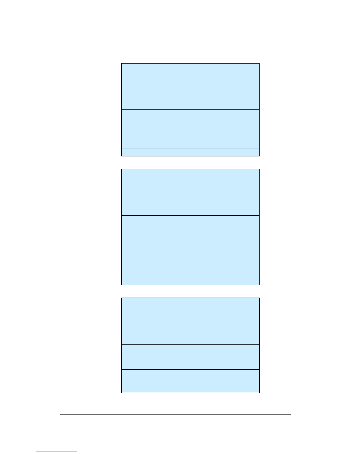
Step
Actions to be taken
Display Indication
1
To enter the Main Menu from normal Operation
Mode, press
2
To select SYSTEM, press 4.
19:23
MAIN MENU
1 SHOW STATUS
2 DISABLE
3 ENABLE
4 SYSTEM
5 SERVICE
6 OUTPUT CONTROL
19:23
MAIN MENU
1 SHOW STATUS
2 DISABLE
3 ENABLE
4 SYSTEM
5 SERVICE
6 OUTPUT CONTROL
SYSTEM
1 DATE AND TIME
2 INFORMATION
3 ACCESS LEVEL 3
4 PRINTER
5 CHANGE LANGUAGE
6 INITIALIZE
7 DAY/NIGHT TIMERS
19:23
SYSTEM
1 DATE AND TIME
2 INFORMATION
3 ACCESS LEVEL 3
4 PRINTER
5 CHANGE LANGUAGE
6 INITIALIZE
7 DAY/NIGHT TIMERS
19:23

Startup Procedure
Commissioning Handbook, AutroSafe Interactive Fire Detection System, Release 4, 116-P-ASAFE-COMMISS/EGB Rev.F, 2014-04-01,
Autronica Fire and Security AS
Page 35
Step
Actions to be taken
Display Indication
3
To select ACCESS LEVEL 3, press 3.
4
To enter ACCESS LEVEL 3, press 1.
5
Enter the password, then press
twice.
SYSTEM
ACCESS LEVEL 3
1 ENTER ACCESS LEVEL 3
2 LEAVE ACCESS LEVEL 3
3 SET PASSWORD
19:23
SYSTEM
ACCESS LEVEL 3
1 ENTER ACCESS LEVEL 3
2 LEAVE ACCESS LEVEL 3
3 SET PASSWORD
19:23
SYSTEM
ACCESS LEVEL 3/ENTER ACCESS LEVEL 3
Enter password:
19:23
SYSTEM
ACCESS LEVEL 3/ENTER ACCESS LEVEL 3
Enter password:
19:23
SYSTEM
ACCESS LEVEL 3/ENTER ACCESS LEVEL 3
Enter password: ****
Successfully Completed
19:23
SYSTEM
ACCESS LEVEL 3/ENTER ACCESS LEVEL 3
Enter password: ****
Successfully Completed
19:23

Verifying the System after
an Upload
Commissioning Handbook, AutroSafe Interactive Fire Detection System, Release 4, 116-P-ASAFE-COMMISS/EGB Rev.F, 2014-04-01,
Autronica Fire and Security AS
Page 36
9. Verifying the System after
an Upload
9.1 General System Verification Procedure
To ensure that the system works properly during normal operation
after an upload, the whole system (control panel, detectors, control
functions) should be verified after an upload.
Step
Description
√
1
To test the panel indicator lights and internal buzzer, press and hold the Reset button for at
least 5 seconds. All indicators are lit and the buzzer is turned on. The test will automatically
stop. The lamp test can be performed in access level 1 (no use of key).
2
Test all operating keys by pressing each key (refer also to Operator’s Handbook):
All buttons will give a short "Beep" when pressed except Mute button, Menu button and
Reset System button (plus the ones that are not supported, see below).
Note that the left/right arrow buttons and the two buttons in the lowermost right hand corner
(indicated with a white line) are not yet supported:
‘
3
Perform a visual and functional inspection of manual call-points and automatic detectors.
4
Disable any alarm transference to the Fire Alarm Routing Equipment -FARE output.
5
Activate the alarm system. Test all sounders by activating an alarm from a corresponding
manual call-point.
6
Test all control functions.
7
Activate alarms from at least one detector/manu al call-point in each zone and a check that
Mute Panel button
Silence Alarms button
Reset System button
Menu button
Close Window button
Alphanumeric keyboard
Manoeuvre buttons

Verifying the System after
an Upload
Commissioning Handbook, AutroSafe Interactive Fire Detection System, Release 4, 116-P-ASAFE-COMMISS/EGB Rev.F, 2014-04-01,
Autronica Fire and Security AS
Page 37
Step
Description
√
all respective outputs are activated.
8
Test the action of any auxiliary operating functions (disabling, cancelling and resetting
buttons).
9
Check the alarm transference outputs by connecting from outgoing outputs (potential free
relay and 24V output) activated by alarm in a zone.
10
Check the fault warning function from detector zones by removing a detector in each zone.
Activate a fault (remove battery fuse) and observe:
- the Fault indicator starts to blink
- a fault warning is displayed
- the internal buzzer is turned ON
- the Fault Warning Routing Equipment (FWRE) output i s activated (if any)
11
Verify all conditions, i.e.:
- Fire Alarm condition
- Fire Warning condition
- Fault Warning condition
- Disablement condition
- Test condition
12
On completion of checks, ensure that only the green "Power" indicator is ON when the
panel is in its idle state (normal operation).
13
Enable alarm transference to the Fire Alarm Routing Equipment -FARE output.
9.2 Verifying Detection Loops During Normal Operation
It may be necessary to verify the detection loops (checking the loop
topology, the types of loop units, the location of loop units, the Loop
Sequence Indexes, etc.) during normal operation using the AS-2000
Loop Diagnostic Tool.
Before applying the tool, prepare the system for the verification as
follows:
Enter the Service Menu (5), select Upgrade (5), then Reboot
System (6).
The system will now enter system fault condition.
Remove fuse A1 and A2 from the Power Board BSF-400.
Connect and apply the tool, and do the necessary verifications.
Alternative 1:
Disconnect a detection loop. Use the AS-2000 Was-box to verify
the loop. Perform a verification for each loop in turn.
Alternative 2:
Disconnect the ribbon cable to BSL-310. Connect the AS-2000.
Run an initialization.
When the verificat ion is co mpleted, disconnect the tool/PC, re-
connect the cables, then re-place the fuses.
Reboot the system again.
1
2
3
AFB A
AFB A"
AFB CT A
4
5
6
AFB Earth Fault Sens
AFB B
AFB B"
7
8
AFB CT B
AFB Earth Fault Sens
J2
J19
S
High Low
J24
J18
+
B
0V
+
A2
0V
+
A1
X11 X10
S5
AFB Earth Fault Off
AFB Earth Fault On
1
OFF
ON
2
OFF
ON
Power Board BSF-400
Fuse A1
and A2

Commissioning Handbook, AutroSafe Interactive Fire Detection System, Release 4, 116-P-ASAFE-COMMISS/EGB Rev.F, 2014-04-01,
Autronica Fire and Security AS
Page 38
10. Upgrading the System
10.1 Introduction
After the very first startup of a system, a running system can be
upgraded at any time using the service menu commands (shown in
the next chapter). The upgrading can be performed from any Fire
Alarm Control Panel BS-420 or Operator Panel BS-430 in the system
(a freely selected panel).
Note that once you have selected a “master” panel for upgrading, the
system will temporarily block all other panels during the upgrade
procedure, preventing the system from being upgraded from other
panels.
This chapter deals with upgrading by means of a USB memory stick.
Upgrading can also be performed by using a computer remotely
connected to a web site (refer to separate handbook).
10.2 Upgrading During Normal Operation (SW/Config)
10.2.1 Introduction
The Service Menu includes submenus which allows you to upgrade
both the system software and the configuration (or either of them)
during normal operation (see following chapters).
Note that if both the software and the configuration are to be
upgraded, the system software and configuration have to be
supported by the same config model. As a general rule, if both the
software and the configuration are to be upgraded, always upgrade
the software version first, then the configuration.
To use the Service Commands, access level 3 is required (refer to
Operator’s Handbook).
Upgrade
Upgrade SW
Upgrade Config
Export Config
Export Log
View Upgrade Status
Reboot System
After an upgrade, a reboot must always be executed for changes
to take effect (software and/or configuration ugrade).
Note that it is possible to upgrade both software and the
configuration in turn bef ore r eboot in g, i.e. it is not nece s s ar y to
reboot after each single upgrade.
NOTE:
When upgrading the
system by means of a
USB memory stick, do
not remove the USB stick
from the USB port until
you are sure that the
upgrade procedure is
completed.
Enter the menu “View
Upgrade Status” to follow
the progress and verify
that the procedure is
completed.
Upgrading the System
Commissioning Handbook, AutroSafe Interactive Fire Detection System, Release 4, 116-P-ASAFE-COMMISS/EGB Rev.F, 2014-04-01,
Autronica Fire and Security AS
Page 39
10.2.2 Upgrading Software During Normal Operation
Note that before executing this command, insert the USB memory
stick with the correct and valid file into one of the USB ports on the
BSA-400 Controller Board.
After the stick is inserted, wait at least 5 seconds before executing
the command.
From the panel front, press 5 to enter the Service Menu (Access
Level 3).
To select Upgrade, press 5.
To Upgrade SW press 1.
To view the upgrade status, the View Upgrade Status command
can be used.
If you do not intend to upgrade the configuration at this point, the
panel has to be rebooted for changes to take effect.
If you also intend to upgrade the configuration, do not reboot at this
point, but go to Upgrade Config (see next chapter).
When the upgrade is completed, press 6 to run the Reboot System
command.
10.2.3 Upgrading Configuration During Normal Operation
Note that before executing this command, insert the USB memory
stick with the correct and valid file into one of the USB ports on the
BSA-400 Controller Board.
After the stick is inserted, wait at least 5 seconds before executing
the command.
From the panel front, press 5 to enter the Service Menu (Access
Level 3).
To select Upgrade, press 5.
To Upgrade Config press 2.
To view the upgrade status, the View Upgrade Status command
can be used.
If you do not intend to upgrade the software at this point (if not
already done), the panel has to be rebooted for changes to take
effect.
If you also intend to upgrade the software (supported by the sam e
config model), do not reboot at this point, but go to Upgrade
Software (see previous chapter).
When the upgrade is completed, press 6 to run the Reboot System
command,.
NOTE:
Do not remove the
USB stick from the
USB port until you
are sure that the
upgrade procedure
is completed.
NOTE:
Do not remove the
USB stick from the
USB port until you
are sure that the
upgrade procedure
is completed.

Upgrading the System
Commissioning Handbook, AutroSafe Interactive Fire Detection System, Release 4, 116-P-ASAFE-COMMISS/EGB Rev.F, 2014-04-01,
Autronica Fire and Security AS
Page 40
10.3 Upgrading when Panels are Added/Remo ved
If panels are added or removed, or it is necessary to change IP
addresses, a reboot must be executed. The continuing procedure is
similar to the startup procedure, chapter 8.
Go to chapter 8 and follow the procedure.
10.4 Upgrading if IP Addresses are to be Changed
If it is necessary to change IP addresses, a reboot must be executed.
The continuing procedur e i s desc r ibed in the startup procedure,
chapter 8.
Go to chapter 8 and follow the procedure.
10.5 Upgrading a Single Panel
If a single panel in a network system for some reason has a wrong
software and/or configuration version, the process of upgrading the
entire system could be both unnecessarily time-consuming, or even
impossible if the software versions are incompatible. To simplify the
version correction in such a case, the system features an upgrade
procedure of a single panel. Before the upgrade procedure is carried
out, the file name of the software and/or configuration file has to be
changed.
Locate the software/configuration file(s) in question on your
computer.
Change the name of the software file:
Add the text _Recovery to the name of the software file as follows:
Example:
The file name AS_V4_3_0_0_C4_34.tar.bz2 is changed to
AS_V4_3_0_0_C4_34_Recovery.tar.bz2
Change the name of the configuration file:
Remove the text representing the “file name” (in this example,
Tiller) and replace it with the text Recovery:
Example;
AC_4_34_Tiller.tar.bz2 is changed to AC_4_34_Recovery.tar.bz2
Copy the file(s) onto your USB memory stick.
Insert the USB memory stick into one of the USB ports on the
BSA-400 Controller Board, then reboot the panel.
The panel will automatically be upgraded.
If the panel has a display, the process similar to the startup
procedure will be shown (chapter 8).
If the panel does not ha ve a display, the process will be indicated
by means of the yellow LED indicator D2 on the BSA-400 board as
follows (see illustration, chapter 10.7.3):
- Slow blink: upgrade in progress
-
Fast blink: upgrade failed
-
Steady yellow light: Upgrade completed, remove stick
to reboot the panel
NOTE:
Do not remove the
USB stick from the
USB port until you
are sure that the
upgrade procedure
is completed.
Upgrading the System
Commissioning Handbook, AutroSafe Interactive Fire Detection System, Release 4, 116-P-ASAFE-COMMISS/EGB Rev.F, 2014-04-01,
Autronica Fire and Security AS
Page 41
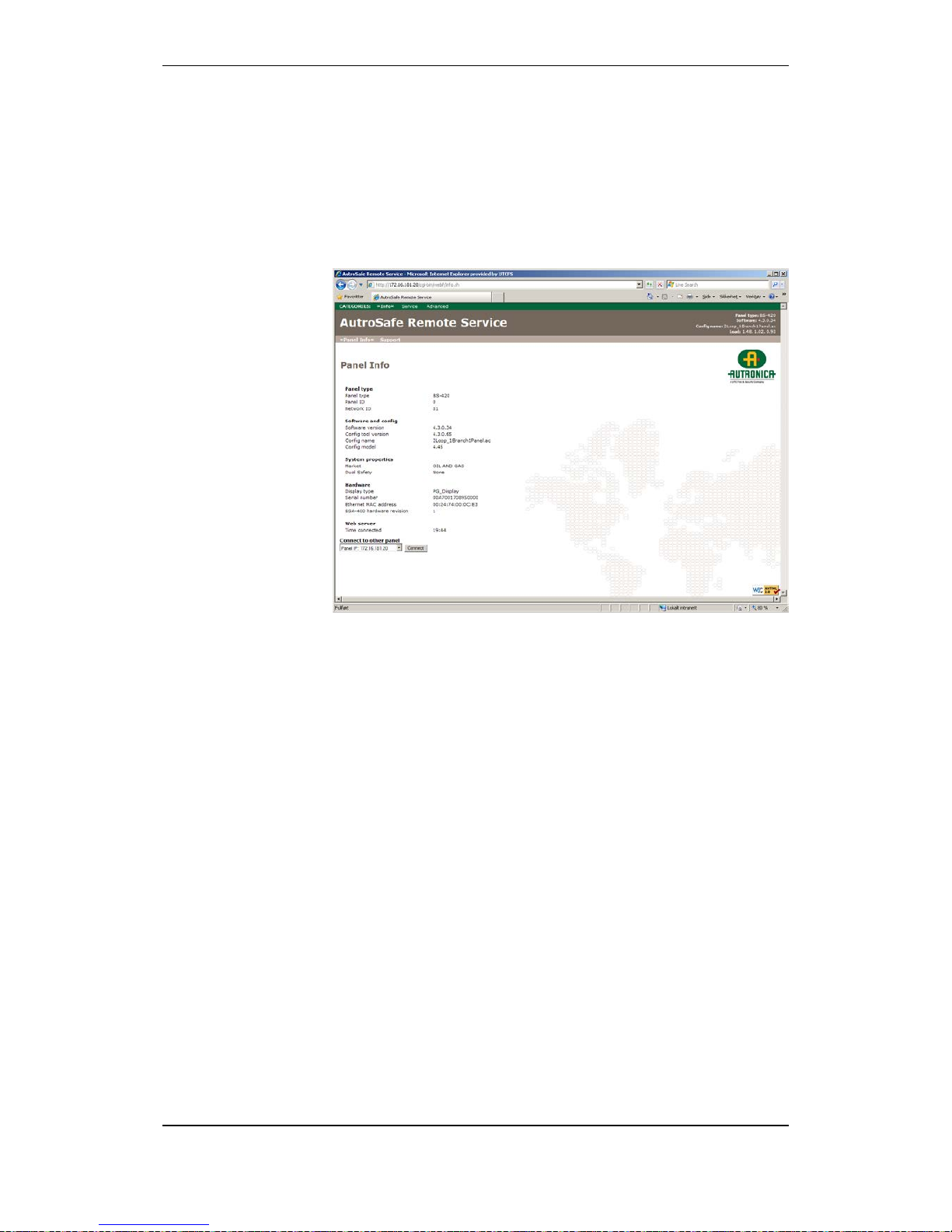
10.6 Upgrading b y Remo te Access to a Web site
Upgrading can be performed by means of a computer with remote
access to a web site providing several service functions.
From the Service menu, press 6 to select Remote Access.
For further information, refer to separate handbook.

Upgrading the System
Commissioning Handbook, AutroSafe Interactive Fire Detection System, Release 4, 116-P-ASAFE-COMMISS/EGB Rev.F, 2014-04-01,
Autronica Fire and Security AS
Page 42
10.7 Upgrading Software Version 4.0.1 to 4.1.1
10.7.1 General
This chapter deals with the upgrade from software version 4.0.1 to
4.1.1.
Before reconfiguring the system or upgrading the system software, a
hardware reset must be executed. All panels belonging to the same
system will be reset and upgrading can then take place.
If the system is in normal operation, go to chapter 10.7.2.
If the system is in system fault condition, go to chapter 10.7.3.
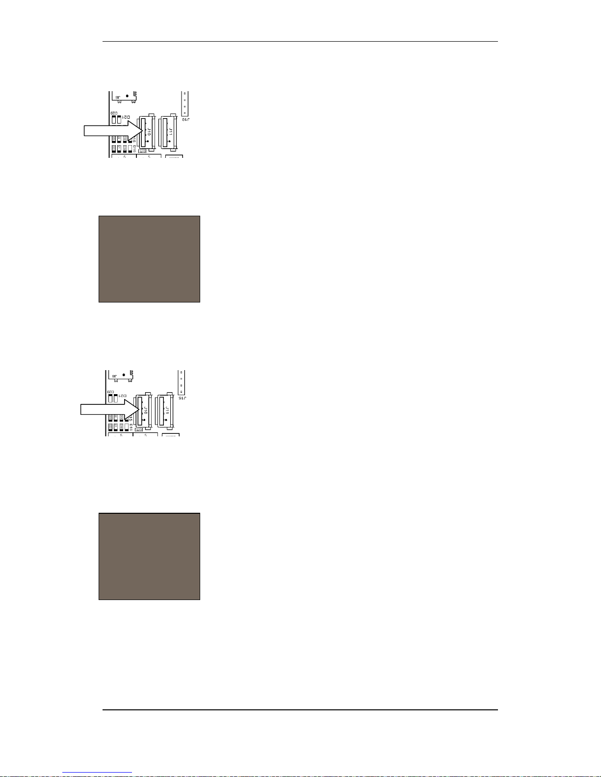
10.7.2 Preparing a System in Normal Operation
Push the reset button S5 less than 1 second to shut down the
panel in a controlled manner.
Wait until the blue LED indicator D22 (see illustration on next page)
goes off.
The panel has now entered system fault condition.
Go to chapter 10.7.3.
IMPORTANT:
Follow the upgrade procedure as described in detail below.
During the upgrade to software version 4.1.1, the system will
enter system fault condition.
Do NOT disconnect the mains power or press the front panel’s
Reset System button.
Press the front panel’s Mute button to silence the buzzer.
Note that a panel that has been upgraded to software version
4.1.1 cannot be downgraded to software version 4.0.1.
Upgrading the System
Commissioning Handbook, AutroSafe Interactive Fire Detection System, Release 4, 116-P-ASAFE-COMMISS/EGB Rev.F, 2014-04-01,
Autronica Fire and Security AS
Page 43
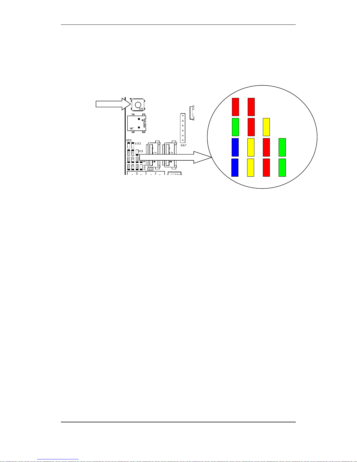
10.7.3 Preparing a System in System Fault Condition
To perform a hard reset, push and hold down the reset button S5
until the red LED indicator D20 and D21 are lit for a short moment
and you hear a click from the relay.
The system will now detect all running panels, and prompt you to
reboot the entire system (all running panels).
Verify that all panels in the system are detected.
Press 2 to select Reboot running panels.
When all panels are rebooted, four selections will appear.
Press 3 (“Upgrade Software”).
Insert the USB memory stick with the valid file into one of the USB
host ports on the BSA-400 Controller Board.
The display will indicate when the uploading is completed.
Remove the USB stick.
The system will automatically reboot.
After a short while, the panel will indicate system fault condition.
Do NOT disconnect the mains power or press the front panel’s
Reset System button.
Press the front panel’s Mute button to silence the buzzer.
When the system is rebooted, the system will be upgraded (the new
system software version) and the system will enter normal operation
mode.
Proceed with the upgrading procedure.
Reset button S5
LEDs
LEDs
Controller Board
BSA-400
D20
D21
D13
D17
D23
D2
D22
D1
D19
D16
D18
D15
D3

Upgrading the System
Commissioning Handbook, AutroSafe Interactive Fire Detection System, Release 4, 116-P-ASAFE-COMMISS/EGB Rev.F, 2014-04-01,
Autronica Fire and Security AS
Page 44
10.8 Upgrading Software Version 4.0.1 or 4.1.1 to 4.3.1
This chapter shows examples of how to upgrade from software
version 4.0.1 or 4.1.1 to 4.3.1.
10.8.1 Example 1: Upgrading all Panels from SW Version 4.0.1 or
4.1.1 to 4.3.1
All panels have software version 4.0.1 or 4.1.1 ins ta lle d.
Upgrade all panels simultaneously by using a USB stick including
program version 4.3.1 (or later when available).
10.8.2 Example 2: Adding a BS-420/BS-430 panel with
SW Version 4.1.1 to a System Running on SW Version 4.3.1
A system is running on software version 4.3.1. A new BS-420/BS-430
panel with software version 4.1.1 installed is going to be added.
Start the new panel without connecting it to the AutroNet.
Install version 4.3.1 by using an USB stick .
Connect the new panel to the system AutroNet.
Restart the system and upgrade the new system configuration data
by using an USB stick.
10.8.3 Example 3: Adding a BC-420 Controller with SW Version 4.1.1 to
a System Running on SW Version 4.3.1
A system is running with software version 4.3.1. A new BC-420
Controller with software version 4.1.1 installed is going to be added.
Disconnect a BS-420 panel from the system AutroNet.
Restart and downgrade the BS-420 panel to run version 4.1.1 by
using a USB stick.
Temporarily, connect the downgraded panel and the new BC-420
Controller together by using an AutroNet connection.
Start the two system units and upgrade them to run version 4.3.1
by using an USB stick.
Connect the two system units to the original system AutroNet.
Restart the system and upgrade the new system configuration data
by using an USB stick.

Commissioning Handbook, AutroSafe Interactive Fire Detection System, Release 4, 116-P-ASAFE-COMMISS/EGB Rev.F, 2014-04-01,
Autronica Fire and Security AS
Page 45
10.8.4 Example 4: Adding a Panel with SW Version 4.3.1 to a
System Running on SW Version 4.1.1
A system is running on software version 4.1.1. A new panel with
software version 4.3.1 installed is going to be added.
Start the system without connecting the new panel to the AutroNet.
Upgrade the system to run version 4.3.1 by using a USB stick.
Connect the new panel to the system AutroNet.
Restart the system and upgrade the new system configuration data
by using an USB stick.

Startup Procedure for a Dual Safety System
Commissioning Handbook, AutroSafe Interactive Fire Detection System, Release 4, 116-P-ASAFE-COMMISS/EGB Rev.F, 2014-04-01,
Autronica Fire and Security AS
Page 46
11. Startup Procedure for a Dual
Safety System
11.1 Introduction
This chapter describes the initial startup procedure of a system
consisting of a Primary System and a Secondary System (AutroSafe
Dual Safety concept).
In principle, the startup procedure is identical to the startup procedure
of a normal system, however, the startup procedure must be carried
out for each system in turn (both the Primary System and the
Secondary System).
The startup of the Primary System can take place from any selected
Fire Alarm Control Panel BS-420 or Operator Panel BS-430 belonging
to the Primary System. Likewise, the startup of a Secondary System
can take place from any panel belonging to the Secondary System.
There are two AutroKeepers BN-180 for each detection loop in a Dual
Safety System. One must be assigned to the Primary System and the
other to the Secondary System (dipswitch settings). Furthermore, the
type of protocol for the AutroFieldBus Protocol Converter BSD-321 (if
used) must be set to Al_Com+ (rotary switch setting).
In the following guidelines, a startup of the Secondary System is
carried out first, then the Primary System. When the startup of both
systems is completed, the Primary System will be in Active Mode (it
controls the detecton loops), and the Secondary System will be in
Standby Mode (ready to take over control of the detection loops).

Startup Procedure for a Dual Safety System
Commissioning Handbook, AutroSafe Interactive Fire Detection System, Release 4, 116-P-ASAFE-COMMISS/EGB Rev.F, 2014-04-01,
Autronica Fire and Security AS
Page 47
11.2 Guidelines – Startup Procedure
The following guidelines apply:
Step Action Chapter
1
Perform the following actions for both the Primary and the
Secondary System:
Verify the detection loops by means of the AS-2000 tool.
Perform a consistency check of the configuration data using the
results from the AS-2000 verification and the data that has been
configured by means of the AutroSafe Configuration Tool.
Assign an AutroFieldBus address to each AutroFieldBus unit.
Assign a Panel ID to each panel by means of switches (dip-switches
and rotary switches on BSA-400).
Assign a Network ID to each panel by means of rotary switches (on
BSA-400).
Verify the system before startup (chapter 7).
3, 4, 5,
6 and 7.
2
Define the type of protocol and assign an Au troFieldBus address
on the AutroFieldBus Protocol Converte r BSD-321
The BSD-321’s default protocol by delivery is Al_Com+. If needed, the
procedure for selecting the protocol type is described below.
Set the actual AutroFieldBus address in the range of 1-31 according
to the specific configuration.
The type of protocol is defined by on-board rotary switches.
To select protocol type:
Apply power to the converter.
Set the switches to 70 (Al_Com+), then press the reset button.
The indicators will start flashing.
When the indicators stop flashing after a short while.
Set the actual AutroFieldBus address, then press reset.
3
Set switches for Primary or Secondary on the AutroKeepers
(BN-180)
Set dipswitch 1 in postion OFF for the BN-180 that belongs to the
Primary System
Set dipswitch 1 in postion ON for the BN-180 that belongs to the
Secondary System
Apply power to BN-180 (24V DV external power).
Startup Procedure for a Dual Safety System
Commissioning Handbook, AutroSafe Interactive Fire Detection System, Release 4, 116-P-ASAFE-COMMISS/EGB Rev.F, 2014-04-01,
Autronica Fire and Security AS
Page 48
Step Action Chapter
4
Apply power to the panel belonging to the S eco n d ary System,
then:
Select Automatic addressing mode to assign an IP Address to each
panel.
Upload configuration data to all panels from the panel in question.
Start system, perform an initialization.
8.1, 8.3,
8.5
5
Apply power to the panel belonging to the P rimary System, then:
Select Automatic addressing mode to assign an IP Address to each
panel.
Upload configuration data to all panels from the panel in question.
Start system, perform an initialization.
8.1, 8.3,
8.5
6
Verify the Dual Safety functionality:
The Primary System is now in Active Mode. The Secondary System is
in Standby Mode (the indicator Dual Safety Stdby on this panel has a
steady yellow light).
Perform a manual transfer of control from the Primary System to the
Secondary System.
From the Primary System, enter the Service Menu, and select Dual
Safety, then Transfer to Secondary
As soon as the loop control is transferred to the Secondary System,
the indicator Dual Safety Stdby will be lit on the Prim ary S ystem’s
panel and will go off on the Secondary System’s panel.
7
Transfer the control back to the Primary System
From the Primary System, enter the Service Menu, and select Dual
Safety, then Transfer to Primary
As soon as the loop control is transferred to the Primary System, the
indicator Dual Safety Stdby will be lit on the Secondary System’s panel.
8
Verify the entire system after an upload.
9
Dual Safety Stdby
Applicable to systems using the Dual Safety concept; a system with
redundant loop control consisting of a Primary and Secondary System.
Steady yellow light:
The panel is in Standby Mode, i.e. this panel does not control the
detection loops. The panel(s) in the other system controls the detection
loops and is in Active Mode.
Blinking light: the panel does not control all detection loops/loop units,
and/or loop control is being transferred. Actions must be taken.

Fault Messages during Uploading
Commissioning Handbook, AutroSafe Interactive Fire Detection System, Release 4, 116-P-ASAFE-COMMISS/EGB Rev.F, 2014-04-01,
Autronica Fire and Security AS
Page 49
12. Fault Messages during
Uploading
12.1 Introduction
During uploading, the system may report possible faults. If such fault
messages occur, the panel in question should be rebooted by means
of the reset button S5 on the Controller Board BSA-400 inside the
panel.
To perform a hard reset, push and hold down the reset button S5
(approximately 6 to10 seconds) until the red LED indicators D20
and D21 are lit for a short moment and you hear a click from the
relay.
12.2 Invalid File on USB Stick
Invalid file is found on the USB stick
Example:
Software: "Software Upgrade, File with syntax
AS_V*_*_*_*_C*_*.tar.bz2 not found in root folder"
Config: "Config Upgrade, File with syntax AC_V4_5_*.tar.bz2 not
found in root folder"
12.3 Data Transmission Timeout
The transmission of data to a panel takes too long (timer) due to a
possible network failure:
"Transfer to panel <NN> timed out"
12.4 Corrupt File
File found, but it is corrupt (crc).
Example:
"Corrupt file AS_V4_0_0_1_C4_5.tar.bz2"

Fault Messages during Uploading
Commissioning Handbook, AutroSafe Interactive Fire Detection System, Release 4, 116-P-ASAFE-COMMISS/EGB Rev.F, 2014-04-01,
Autronica Fire and Security AS
Page 50
12.5 Fail to Unpack Files
If the unpacking of files on a panel is not successful, one of the
following error messages may occur:
"Failed to unpack, file system error on panel <NN>"
"Failed to unpack, panel error on panel <NN>"

Autronica is a leading innovator, manufacturer and supplier of fire safety equipment. Our
products ensure safety in applications on land and sea worldwide. The company is owned by
United Technologies Corporation (UTC) and employs more than 380 people with great skill and
experience in the developing, manufacturing and marketing of fire safety equipment.
Autronica Fire and Security AS is an international company based in Trondheim, a dynamic city
known as the technological hotspot of Norway.
Protecting life, environment and property
Autronica Fire and Security AS
Haakon VIIS gt. 4, NO-7041 Trondheim, Norway | Tel: +47 90 90 55 00 | Fax: +47 73 58 25 01
E-mail: info@autronicafire.no | www.autronicafire.com
 Loading...