


116-P-ASAFE-INSTALL/DGB Rev. I, 2014-04-01, Autronica Fire And Security AS
Installation Handbook
AutroSafe Interactive Fire Detection System
Release 4

COPYRIGHT ©
This publication, or parts thereof, may
not be reproduced in any form, by any
method, for any purpose.
Autronica Fire and Security AS and its
subsidiaries assume no responsibility
for any errors that may appear in the
publication, or for damages arising
from the information in it. No
information in this publication should
be regarded as a warranty made by
Autronica Fire and Security AS. The
information in this publication may be
updated without notice.
Product names mentioned in this
publication may be trademarks. They
are used only for identification.
Installation Handbook, AutroSafe Interactive Fire Detection System, 116-P-ASAFE-INSTALL/DGB Rev. I, 2014-04-01, Autronica Fire and Security
E-1676
This product contains static-sensitive devices . Avoi d an y electrost a tic dis char ge.
The WEEE Directive
When the marking belo w is shown on the
product and/or its liter ature, it means t hat
the product should n ot be disposed with
other household wastes at the en d of its
life cycle. During waste treatment,
disposal and collection, please separate
the product from other types of wastes
and recycle it responsi bly to promote the
sustainable reuse of material resources.
This product should not be mixed with
other commercial wastes for disposal.

Installation Handbook, AutroSafe Interactive Fire Detection System, Release 4, 116-P-ASAFE-INSTALL/DGB Rev. I, 2014-04-01,
Autronica Fire and Security AS
Page 3
Table of Contents
1. Introduction ...................................................................... 7
1.1 About the Handbook .......................................................................... 7
1.2 The Reader ....................................................................................... 7
1.3 Reference Documentation................................................................. 8
2. Pre-installation ................................................................. 9
2.1 Location ............................................................................................. 9
2.2 Environmental Requirements ............................................................ 9
2.3 Mounting Height / Space Requirement ............................................. 9
3. System Units – Overview ................................................ 10
4. Loop Panels – Overview .................................................. 13
5. Mounting Instructions ..................................................... 14
5.1 Introduction ........................................................................................ 14
5.2 Mounting Fire Alarm Control Panel BS-420 / Controller BC-420 ...... 15
5.3 Mounting the Operator Panel BS-430 ............................................... 17
5.4 Mounting Repeater Panel BU-BV-420 .............................................. 18
5.5 Mounting Loop Panels (BV-110 and BU-110) ................................... 20
5.6 Mounting Power Cabinet BP-405 ...................................................... 21
5.7 Mounting Power Supply Unit BPS-405 / BPS-410 ............................ 24
5.8 Inserting Text Foils ............................................................................ 25
5.9 Cable Inlets / Outlets ......................................................................... 26
5.10 Cut Out Dimensions for Flush Mounting in a Wall ............................ 27
5.10.1 Repeater Panel BU-BV-420 .................................................... 27
5.10.2 Operator Panel BS-430 ........................................................... 28
6. Power Consumption ........................................................ 29
6.1 Mains Power ...................................................................................... 29
6.1.1 BPS-405 .................................................................................. 29
6.1.2 BPS-410 .................................................................................. 29
6.2 System Units ..................................................................................... 29
6.3 Loop Units ......................................................................................... 29
6.4 Phoenix Ethernet Switches ............................................................... 30
6.5 Power Design Considerations ........................................................... 30
7. Cable Connection Overview ............................................ 31
8. Connecting Internal Cables ............................................. 32
8.1 Overview – BS-420 / BC-420 ............................................................ 32
8.2 BS-420 / BC-420 ............................................................................... 33
8.2.1 AL_Com+ Connection on Controller Board BSA-400 ............. 33

Installation Handbook, AutroSafe Interactive Fire Detection System, Release 4, 116-P-ASAFE-INSTALL/DGB Rev. I, 2014-04-01,
Autronica Fire and Security AS
Page 4
8.2.2 AL_Com+ Connection on Communication Module BSL-
310 .......................................................................................... 33
8.2.3 Multifunction Serial Port Connection on Controller Board
BSA-400 .................................................................................. 34
8.2.4 Multifunction Serial Port Connection on Terminal Block,
List L1 ...................................................................................... 34
8.2.5 Multifunction Serial Port Connection Overview – BSA-400 .... 35
8.3 BC-440 .............................................................................................. 35
8.4 Internal Earth Cabling ........................................................................ 36
9. Connecting External Ca bles ........................................... 37
9.1 Introduction ........................................................................................ 37
9.2 Before Connecting Cables ................................................................ 37
9.3 Mains Wiring - Two-pole Disconnect Device ..................................... 37
9.3.1 Voltage Selection 115/230VAC on the BPS-405 .................... 38
9.3.2 115/230VAC Voltage BPS-410 ............................................... 38
9.4 AutroFieldBus Connections ............................................................... 39
9.4.1 Connections to BS-420/BC-420 - Terminal Block (List 1)....... 39
9.4.2 Connections to Connector J2, Power Board BSF-400 ........... 40
9.4.3 Example of the Interconnection of Several Power
Cabinets .................................................................................. 40
9.5 Connection of Network Cables (AutroNet) ........................................ 41
9.5.1 AutroNet Redundant Star Topology ........................................ 41
9.5.2 AutroNet Single Star Topology ............................................... 42
9.5.3 AutroNet Ring Topology .......................................................... 43
9.5.4 Connection to Controller Board BSA-400 ............................... 44
9.5.5 Common Earth Connections ................................................... 44
9.6 RS-485 Connections to Terminal Block, List L1 ............................... 45
9.7 RS-422 Connections to Terminal Block, List L1 ............................... 45
9.8 RS-232 Connections to Terminal Block, List L1 ............................... 46
9.9 24V Power Connections .................................................................... 46
9.9.1 Connections to Controller Board BSA-400 ............................. 46
9.9.2 Connections to Power Board BSF-400 ................................... 47
9.9.3 Power Connection Overview ................................................... 48
9.10 Mains Power Connections................................................................. 49
10. Installing I/O Modules ...................................................... 50
10.1 Introduction ........................................................................................ 50
10.2 Front View of I/O Module................................................................... 50
10.3 Mounting / Removing I/O Modules .................................................... 51
10.3.1 General ................................................................................... 51
10.3.2 Mounting ................................................................................. 51
10.3.3 Removing ................................................................................ 52
10.3.4 Before Connecting Cables ...................................................... 52
10.4 Data Sheets - I/O Modules ................................................................ 52
11. Dual Safety Installation ................................................... 53
11.1 Dual Safety System Overview ........................................................... 53
11.2 Rules of Thumb ................................................................................. 53
11.2.1 Example 1: Connections Using AL_Com+ only ...................... 54
11.2.2 Example 2: Connections using both AL_Com+ and
AutroFieldBus .......................................................................... 55
11.3 Connections Overview ...................................................................... 55
11.3.1 Connections – AutroKeeper BN-180 ....................................... 57
11.3.2 Switch Settings – AutroKeeper BN-180 .................................. 57

Installation Handbook, AutroSafe Interactive Fire Detection System, Release 4, 116-P-ASAFE-INSTALL/DGB Rev. I, 2014-04-01,
Autronica Fire and Security AS
Page 5
12. Cable Specificati ons ........................................................ 58
13. Service and Maintenance ................................................ 59
13.1.1 Monthly Maintenance .............................................................. 59
13.1.2 Annual Service and Maintenance ........................................... 60
13.1.3 SIL2 Approved Systems ......................................................... 61
14. Appendix A - Controller Board BSA_400 ....................... 62
14.1 Circuit Board Layout .......................................................................... 62
14.2 Location inside Fire Alarm Control Panel BS-420 ............................. 63
14.3 Description ........................................................................................ 63
14.4 Internal LED Indicators ...................................................................... 64
14.5 Power Input Connector J18 (screw terminal) .................................... 64
14.6 Two-s tage Push But ton R e set (S5) ................................................... 65
14.7 USB Ports (J10, J11) ......................................................................... 65
14.8 Multifunction Serial Port Connector J3 - AutroFieldBus and
Fault Relay ........................................................................................ 66
14.9 AutroFieldBus Connections ............................................................... 67
14.9.1 Ribbon Cable Connector BSA-400 to Terminal Block L1 ....... 67
14.10 Multifunction Seri al Port D i psw itch Sett in gs – Switch S6 (RS-
232, RS-422, RS-485) ....................................................................... 68
14.11 Multifunction Seri al Port D i psw itch Sett in gs – Switch S7 .................. 68
14.12 RS-485 Connections ......................................................................... 69
14.12.1 Ribbon Cable Connector BSA-400 to Terminal Block L1 .... 69
14.12.2 Switch Setting – Switc h S6 and S7 ...................................... 69
14.13 RS-422 Connections ......................................................................... 69
14.13.1 Ribbon Cable Connector BSA-400 to Terminal Block L1 .... 69
14.13.2 Switch Setting – Switc h S6 and S7 ...................................... 69
14.13.3 Schematic of port equivalent: ............................................... 70
14.14 RS-232 Connections ......................................................................... 70
14.14.1 Ribbon Cable Connector BSA-400 to Terminal Block L1 .... 70
14.14.2 Switch Setting – Switc h S6 and S7 ...................................... 70
14.15 Serial Debug Connector J21 ............................................................. 71
14.16 AL_Com+ Connector J5 .................................................................... 71
14.17 LCD Backlight Connector J17 ........................................................... 72
14.18 Ethernet Ports (RJ-45 Connectors) ................................................... 72
14.18.1 Ethernet Straight Through Cable ......................................... 73
14.19 Fault messages Power Board BSF-400 ............................................ 73
15. Appendix B - Power Supply ............................................ 75
15.1 Power Cabinet and Power Units ....................................................... 75
15.1.1 Power Cabinet BP-405 ........................................................... 75
15.1.2 Power Unit BPS-405 ............................................................... 75
15.1.3 Power Unit BPS-410 ............................................................... 75
15.2 Circuit Board Layout BSF-400 .......................................................... 76
15.3 Description ........................................................................................ 77
15.4 Power Block Diagram – Example ...................................................... 77
15.5 Batteries ............................................................................................ 78
15.5.1 Power Unit BPS-405 ............................................................... 78
15.5.2 Power Unit BPS-410 ............................................................... 79
15.6 Battery Charging ............................................................................... 79
15.7 Button S2 – Start on S2 on Standby Source ..................................... 80
15.8 Configuration Settings ....................................................................... 81
15.9 Dipswitch table – S5 and S6 ............................................................. 82

Installation Handbook, AutroSafe Interactive Fire Detection System, Release 4, 116-P-ASAFE-INSTALL/DGB Rev. I, 2014-04-01,
Autronica Fire and Security AS
Page 6
15.10 Connectors ........................................................................................ 83
15.11 Fault Relay Watchdog J26 ................................................................ 84
15.12 Battery Resistance Measurement ..................................................... 85
15.13 Electronic fuses ................................................................................. 85
15.13.1 Power outputs ...................................................................... 85
15.13.2 Battery Input ......................................................................... 86
15.14 Part of an AutroFieldBus Network ..................................................... 86
15.15 Power Unit BPS-405 / BPS-410 as Standalone ................................ 86

Introduction
Installation Handbook, AutroSafe Interactive Fire Detection System, Release 4, 116-P-ASAFE-INSTALL/DGB Rev. I, 2014-04-01,
Autronica Fire and Security AS
Page 7
1. Introduction
1.1 About the Handbook
This handbook is intended to provide all necessary information for the
installation of the AutroSafe Interactive Fire Detection System,
Release 4. It also gives detailed information on connections to
Autronica’s local area network (AutroNet) and guidelines for the
installation and addressing of loop units.
Information on the connection of detectors and other loop units to the
detection loop is found in a separate handbook, Connecting Loop
Units, 116-P-CONNECTLOOPUNIT/GBD (pdf filname
connectloopunit_gbd).
The chapter «Service and Maintenance» outlines the recommended
monthly and annual service and maintenance procedures that should
be performed after the system has been commissioned.
1.2 The Reader
The handbook is intended to be used by Autronica Fire and Secur it y
trained service and technical personnel who are responsible for the
installation of the AutroSafe Interactive Fire Detection System,
Release 4.
Note that this handbook deals with the mechanical and electrical
installation only. All tasks described in the handbook are to be
performed without applying power to the system.
Power must not be applied before commissioning, refer to
Commissioning Handbook.
!
POWER OFF!

Introduction
Installation Handbook, AutroSafe Interactive Fire Detection System, Release 4, 116-P-ASAFE-INSTALL/DGB Rev. I, 2014-04-01,
Autronica Fire and Security AS
Page 8
1.3 Reference Documentation
The table below shows an overview of the technical marketing
documentation for AutroSafe Interactive Fire Detection System,
Release 4.
Document Name
Part number
File name
System Description
116-P-ASAFE-SYSTEMD/EGB
asafesystemd_egb
Installation Handbook
116-P-ASAFE-INSTALL/DGB
asafeinstall_dgb
Commissioning Handbook
116-P-ASAFE-COMMISS/EGB
asafecommiss_egb
User Guide, Remote Access
116-P-ASAFE-REMOTEAC/EGB
asaferemoteac_egb
Connecting Loop Units
116-P-CONNECTLOOPUNIT/DGB
connectloopunit_dgb
Operator’s Handbook
116-P-ASAFE-OPERATE/FGB
asafeoperate_fgb
User Guide
116-P-ASAFE-USERGUI/LGB
asafeusergui_lgb
Wall Chart
116-P-ASAFE-WALLCHA/LGB
asafewallcha_lgb
Menu Structure
116-P-ASAFE-MENUSTR/MGB
asafemenustr_mgb
Datasheet; Fire Alarm Control Panel BS-420
116-P-BS420/CGB
bs420_cgb
Datasheet; Operator Panel BS-430
116-P-BS430/CGB
bs430_cgb
Datasheet; Repeater Panel BU-BV-420
116-P-BUBV420/CGB
bubv420_cgb
Datasheet; Fire Brigade Loop Panel BU-110
116-P-BU110/CGB
bu110_cgb
Datasheet; Information Loop Panel BV-110
116-P-BV110/CGB
bv110_cgb
Datasheet; Controller BC-420
116-P-BC420/CGB
bc420_cgb
Datasheet; Controller Unit Rack BC-440
116-P-BC440/CGB
bc440_cgb
Datasheet; Power Cabinet BP-405
116-P-BP405/CGB
bp405_cgb
Datasheet; Power Unit BPS-405
116-P-BPS405/CGB
bps405_cgb
Datasheet; Power Unit BPS-410
116-P-BPS410/CGB
bps410_cgb
Datasheet; AutroKeeper BN -180
116-P-BN180/CGB
bn180_cgb
For detailed technical information on Phoenix Ethernet Switches, refer
to Phoenix Contact web site at
http://select.phoenixcontact.com/phoenix/dwl/dwlfr1.jsp?lang=en

Pre-installation
Installation Handbook, AutroSafe Interactive Fire Detection System, Release 4, 116-P-ASAFE-INSTALL/DGB Rev. I, 2014-04-01,
Autronica Fire and Security AS
Page 9
2. Pre-installation
2.1 Location
The Fire Alarm Control Panel or Operator Panel must be located in, or
nearby, the entrance according to local regulations and in consultation
with the fire brigade.
Repeater Panels (Fire Brigade Pan els and Inf or mation Panels),
Controllers and Power Cabinets must be placed according to local
regulations and in consultation with the fire brigade.
2.2 Environmental Requirements
For information on environmental requirements for AutroSafe
equipment, refer to separate datasheets.
2.3 Mounting Height / S pace Requir ement
To ensure optimal readability of the Fire Alarm Control Panel's
display, the recommended mounting height of this cabinet top is
approximately 175 cm above the floor. Other panels should be
mounted accordingly.
175 cm

System Units – Overview
Installation Handbook, AutroSafe Interactive Fire Detection System, Release 4, 116-P-ASAFE-INSTALL/DGB Rev. I, 2014-04-01,
Autronica Fire and Security AS
Page 10
3. System Units – Overview
For detailed information on each system unit, refer to separate
datasheets.
System Unit
Description
Fire Alarm Control Panel BS-420
BS-420 is a complete fire alarm control panel with full
operation capabilities. The panel serves as an
operating panel for one or several defined operation
zones. All alarm handling and system features can be
controlled and monitored from the panel.
The panel provides connections for:
2 Ethernet ports and 2 USB host ports
1 RS-232, RS-422 or RS-485 serial port for
communication with third party equipment
1 AutroFieldBus (AFB) interface
1 AlCom+ interface
FailSafe relay output
Power redundant
Dimensions:
HxWxD (mm): 350 x 350 x 194
Operator Panel BS-430
BS-430 serves as an operating panel for one or
several defined operation zones.
All alarm handling and system features can be
controlled and monitored from the panel.
Dimensions:
HxWxD (mm): 350 x 350 x 84
Repeater Panel BU-BV-420
The Repeater Panel BU-BV-420 serves as both a Fire
Brigade Panel and an Information Panel. Settings on a
dipswitch determine the type of panel.
The Fire Brigade Panel displays alarms and allows you
to operate alarms and receive additional information
related to the relevant operation zone.
The Information Panel serves as an indication device
only. It provides information related to the defined
operation zone(s).
Dimensions:
HxWxD (mm): 195 x 350 x 84

System Units – Overview
Installation Handbook, AutroSafe Interactive Fire Detection System, Release 4, 116-P-ASAFE-INSTALL/DGB Rev. I, 2014-04-01,
Autronica Fire and Security AS
Page 11
Controller BC-420
The Controller, BC-420, serves as a connection unit
for the detection loop, alarm sounders, controls and
inputs.
It can accommodate up to a maximum of 12 modules.
The panel provides connections for:
2 Ethernet ports and 2 USB host ports
1 RS-232, RS-422 or RS-485 serial port for
communication with third party equipment
1 AutroFieldBus (AFB) interface
1 AlCom+ interface
FailSafe relay output
Dimensions:
HxWxD (mm): 350 x 350 x 194
Controller BC-440
The Controller Rack Unit BC-440 serves as a
connection unit for the detection loop, alarm sounders,
controls and inputs. It is a variant of the BC-420
Controller prepared for rack installations. Together
with the IO modules the unit will have the full
functionality of the BC-420 Contro ll er.
Dimensions:
3Ux12HPx200mm
Power Cabinet BP-405
The Power Cabinet BP-405 provides space for two
12V/18Ah batteries (not included). The power supply
and battery brackets are already mounted when the
cabinet is delivered from the factory.
The cabinet provides:
Power Board BSF-40 0, inc ludi ng:
AutroFieldBus interface
115VAC /230VAC input
6 outputs 24VDC (max. 2A each)
1 fault relay output
Dimensions:
HxWxD (mm): 420 x 346 x 146
System Units – Overview
Installation Handbook, AutroSafe Interactive Fire Detection System, Release 4, 116-P-ASAFE-INSTALL/DGB Rev. I, 2014-04-01,
Autronica Fire and Security AS
Page 12
Power Unit BPS-405 / BPS-410
BPS-405: 24V/5A power supply
BPS-410: 24V/10A power supply
Both units include:
Power Board BSF-40 0, inc ludi ng:
AutroFieldBus interface
115VAC /230VAC input
6 outputs 24VDC (max. 2A each)
1 fault relay output
Dimensions:
HxWxD (mm): 130 x 259 x 120
Loop Panels – Overview
Installation Handbook, AutroSafe Interactive Fire Detection System, Release 4, 116-P-ASAFE-INSTALL/DGB Rev. I, 2014-04-01,
Autronica Fire and Security AS
Page 13
4. Loop Panels – Overview
The 100-series provides the following panels and wall brackets:
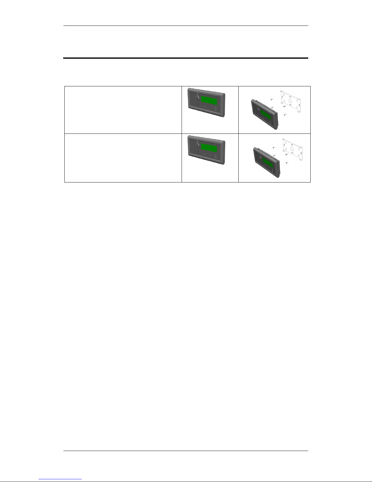
Information Loop Panel (BV-110)
Mounted onto a wall bracket (UD-732).
Dimensions (mm):
HxWxD (mm): 310 x 154 x 45
Fire Brigade Loop Panel (BU-110)
Mounted onto a wall bracket (UD-732).
Dimensions (mm):
HxWxD (mm): 310 x 154 x 45
Mounting Instructions
Installation Handbook, AutroSafe Interactive Fire Detection System, Release 4, 116-P-ASAFE-INSTALL/DGB Rev. I, 2014-04-01,
Autronica Fire and Security AS
Page 14
5. Mounting Instructions
5.1 Introduction
This following chapters deal with the mounting of:
Fire Alarm Control Panel BS-420 / Controller BC-420
Operator Panel BS-430
Repeater Panel BU-BV-420 (Fire Brigade Panel / Information
Panel)
Loop Panels (Information Loop Panel BV-110 and Fire Brigade
Loop Panel BU-110)
Power Cabinet BP-405
Power Units BPS-405 and BPS-410
The following is delivered together with the system units:
Fireman’s key (delivered with all system units, except for BC-420
and BP-405/BPS-405/BPS-410)
Unbraco key (to lock/unlock the front panel) – (not delivered with
BP-405 /BPS-405/BPS-410)
Plastic cap to cover the key hole (Repeater Panel only; when
Repeater Panel BU-BV-420 is to be used as an Information Panel)
11 Rubber glands for entry of external cables
Text foils
A general description of flush mounting Repeater Panel BU-BV-420
and Operator Panel BS-430 in a wall is described in a chapter 5.10.
For information on mounting the Controller Rack BC-440, refer to
separate datasheet.
This product contains static-sensitive devices .
Always use an antistatic wrist strap / earth bracelet to avoid any
electrostatic discharge.
E-1676

Mounting Instructions
Installation Handbook, AutroSafe Interactive Fire Detection System, Release 4, 116-P-ASAFE-INSTALL/DGB Rev. I, 2014-04-01,
Autronica Fire and Security AS
Page 15
5.2 Mounting Fire Alarm Control Panel BS-420 /
Controller BC-420
Instructions
Remarks
Illustrations
Unlock the front panel
by turning the unbraco
key clockwise.
Open the front panel.
In order to easily
access the
mounting holes
when mounting
the cabinet, the
front panel should
be removed.
Disconnect both ribbon
cables from the front
panel.
Unscrew and disconnect
the earth cable from the
termination block inside
the cabinet.
Note: Do NOT
unscrew the earth
cable from the
connection point
on the front panel
(PE=Protective
Earth).
Loosen the 4 wing nuts
located on the right and
left hand side of the
cabinet, then close the
front panel, and remove
the front panel from the
cabinet.
Mark and drill the 3
holes according to the
illustration.
The cabinet has 3
mounting holes
located at the
rear. The 2 upper
holes are of keyhole-type.
Partly fasten the upper

Mounting Instructions
Installation Handbook, AutroSafe Interactive Fire Detection System, Release 4, 116-P-ASAFE-INSTALL/DGB Rev. I, 2014-04-01,
Autronica Fire and Security AS
Page 16
Instructions
Remarks
Illustrations
screws.
Hang the cabinet onto
the upper screws.
Partly fasten the bottom
screw.
Tighten all screws.
Feed all the external
cables into the cabinet
from the top or bottom
through the suitable
cable inlets.
For detailed
information on the
connection of
external cables,
see chapter
9.
Reassemble the front
panel and tighten the 4
wing nuts.
Reconnect the cables
between the front panel
and the cabinet.
Insert the text foils (in
the appropriate
language) into their
respective positions.
For detailed
description of the
various text foils,
see chapter
5.8.

Mounting Instructions
Installation Handbook, AutroSafe Interactive Fire Detection System, Release 4, 116-P-ASAFE-INSTALL/DGB Rev. I, 2014-04-01,
Autronica Fire and Security AS
Page 17
5.3 Mounting the Operator Panel BS-430
Instructions
Remarks
Illustrations
Unlock the front panel
by turning the unbraco
key clockwise.
Open the front panel.
In order to easily
access the
mounting holes
when mounting
the cabinet, the
front panel should
be removed.
Unscrew and disconnect
the earth cable from the
termination point inside
the cabinet.
Note: Do NOT
unscrew the earth
cable from the
connection point
on the front panel
(PE=Protective
Earth).
Unscrew the 4 wing nuts
located on the right and
left hand side of the
cabinet, then close the
front panel, and remove
the front panel from the
cabinet.
Mark and drill the 3
holes.
The cabinet has 5
mounting holes
located at the
rear. The 3 upper
holes are of keyhole-type.
Partly fasten the upper
screws.
Hang the cabinet onto
the upper screws.
Partly fasten the bottom
screw.
Tighten all screws.
Feed all the external
cables into the cabinet
from the top through the
suitable cable inlets.
For detailed
information on the
connection of
external cables,
see chapter
9.
Mounting Instructions
Installation Handbook, AutroSafe Interactive Fire Detection System, Release 4, 116-P-ASAFE-INSTALL/DGB Rev. I, 2014-04-01,
Autronica Fire and Security AS
Page 18
Instructions
Remarks
Illustrations
Reassemble the front
panel and tighten the 4
wing nuts.
Reconnect the earth
cable to the termination
point inside the cabinet
(PE=Protective Earth).
Insert the text foils (in
the appropriate
language) into the their
respective positions.
For detailed
description of the
various text foils,
see chapter
5.8.
5.4 Mounting Repeater Panel BU-BV-420
Instructions
Remarks
Illustrations
Unlock the front panel
by turning the unbraco
key clockwise.
Open the front panel.
In order to easily
access the
mounting holes
when mounting
the cabinet, the
front panel should
be removed.
Unscrew and disconnect
the earth cable from the
termination point inside
the cabinet.
Note: Do NOT
unscrew the earth
cable from the
connection point
on the front panel
(PE=Protective
Earth).
Unscrew the 4 wing nuts
located on the right and
left hand side of the
cabinet, then close the
front panel, and remove
the front panel from the
cabinet.
Mark and drill all 3
holes.
The cabinet has 5
mounting holes
located at the
rear. The upper 3
holes are of keyhole-type.
Partly fasten the upper
screws.
Hang the cabinet onto
the upper screws.

Mounting Instructions
Installation Handbook, AutroSafe Interactive Fire Detection System, Release 4, 116-P-ASAFE-INSTALL/DGB Rev. I, 2014-04-01,
Autronica Fire and Security AS
Page 19
Instructions
Remarks
Illustrations
Partly fasten the bottom
screw.
Tighten all screws.
Feed all the external
cables into the cabinet
from the top through the
suitable cable inlets.
For detailed
information on
cable
connections, see
chapter
9.
Reassemble the front
panel and tighten the 4
wing nuts.
Reconnect the earth
cable to the termination
point inside the cabinet
(PE=Protective Earth).
Set the appropriate
dipswitch settings on
dipswitch S2 (Controller
Board BSA-400)
according to the type of
panel (either a Fire
Brigade Panel or an
Information Panel).
The Repeater
Panel BU-BV-420
serves as both a
Fire Brigade
Panel and an
Information Panel.
Fire Brigade Panel
S2-1 ON
S2-2 ON
S2-3 OFF
S2-4 OFF
Information Panel
S2-1 ON
S2-2 OFF
S2-3 ON
S2-4 OFF
If the panel is to be used
as an Information Panel,
snap the plastic cap on
top of the keyhole.
The Information
Panel is an
indication device
only.
The plastic
covering is
delivered together
with the panel.
Insert the text foils (in
the appropriate
language) into the their
respective positions.
For detailed
description of the
various text foils,
see chapter
5.8.
S2

Mounting Instructions
Installation Handbook, AutroSafe Interactive Fire Detection System, Release 4, 116-P-ASAFE-INSTALL/DGB Rev. I, 2014-04-01,
Autronica Fire and Security AS
Page 20
5.5 Mounting Loop Pane ls (BV-110 and BU-110)
Instructions
Illustrations
Find the text foils in the relevant
language for the panel, and insert the
text foils in the correct locations (there
are two different foils in one foil kit
Through the small hole near the slot,
use a small screwdriver or similar to
slightly bend the edge (approx. 1mm) of
each foil until the edge slips behind the
opening of the slot.
Mount the wall bracket onto the wall.
Make sure to mount the panel onto a wall
with a flat surface in order to maintain IP
rating (IP32).
252,3
153
Ø40
12
Ø6
82
60
11
171
Connect AL_Com loop cables to the
correct terminal points on connector J3:
J3-1: In+
J3-2: InJ3-3: Out+
J3-4: Out-
Place and centre the lower part of the
panel onto the lower part of the bracket,
then simply push the upper part of the
panel towards the bracket until it snaps
on.

Mounting Instructions
Installation Handbook, AutroSafe Interactive Fire Detection System, Release 4, 116-P-ASAFE-INSTALL/DGB Rev. I, 2014-04-01,
Autronica Fire and Security AS
Page 21
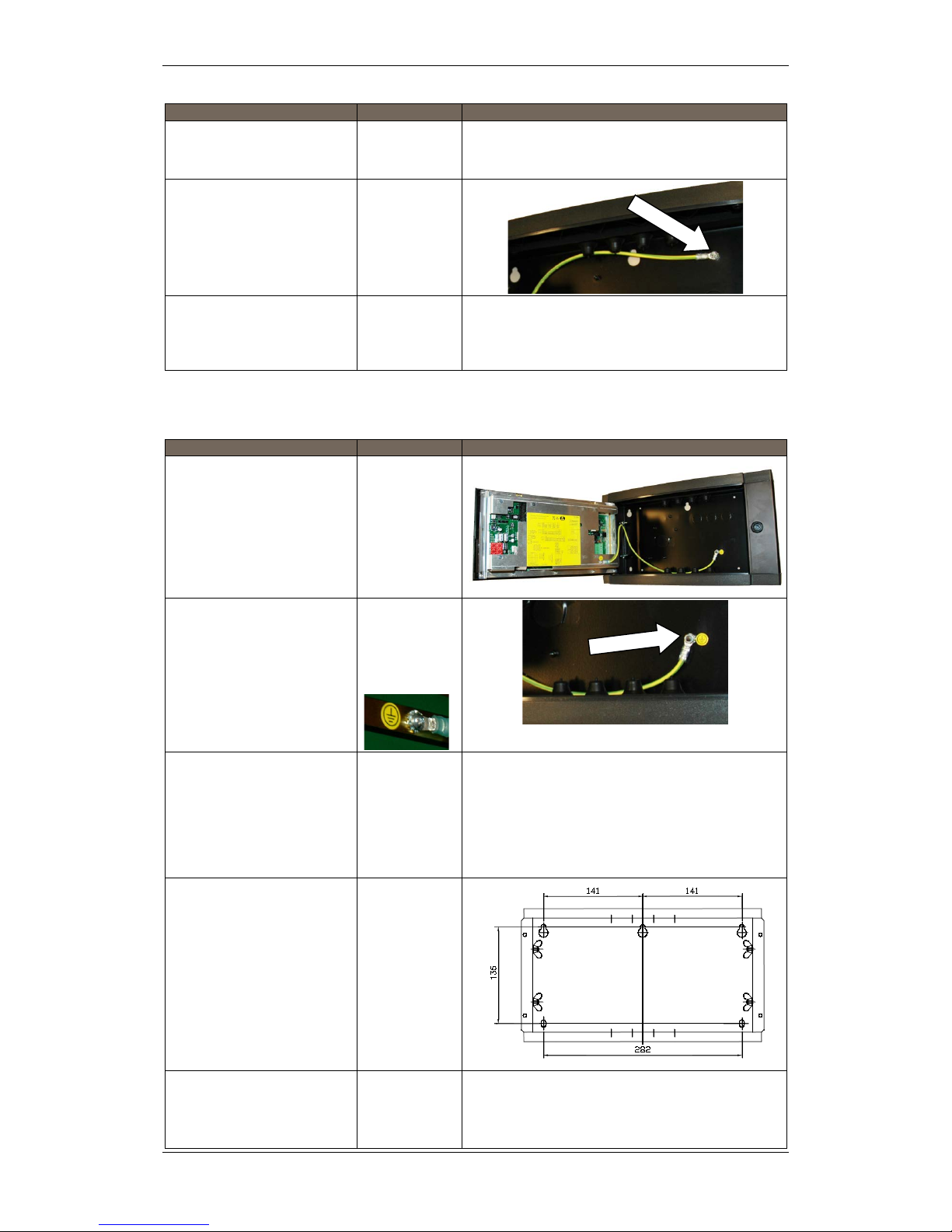
5.6 Mounting Power Cabinet BP-405
AutroSafe Release 4 provides a Power Cabinet BP-405 with space for
two 12V/18Ah batteries (not included). The power supply and battery
brackets are already mounted when the cabinet is delivered from the
factory.
The mounting procedure deals with the m ounting of the cabinet and
the internal batteries.
Note that the Power Cabinet can be placed under and fastened
directly to a Fire Alarm Control Panel BS-420 or a Controller BC-420.
The position of the 11 cable inlets/outlets at the bottom of the
BS-420/BC-420 match exactly with the ones on the top of the Power
Cabinet BP-405.
Instructions
Remarks
Illustrations
Unlock the front door
by unscrewing the
door lock screws
Open the front door.
Mark and drill holes.
The cabinet has 3 mounting
holes located at the rear.
The 2 upper holes are of
key-hole-type.
Partly fasten the
upper screws.
Hang the cabinet onto
the upper screws.
Partly fasten the
bottom screw.
Tighten all screws.

Mounting Instructions
Installation Handbook, AutroSafe Interactive Fire Detection System, Release 4, 116-P-ASAFE-INSTALL/DGB Rev. I, 2014-04-01,
Autronica Fire and Security AS
Page 22
Instructions
Remarks
Illustrations
Insert both batteries in
their appropriate
locations with the
battery poles facing
up and towards the
outside of the cabinet.
Tighten the strap
around each battery.
Connect the black
cable from the
connector on the
Power Board to the
minus pole on the
uppermost battery.
Connect the red cable
from the connector on
the Power Board to
the plus pole on the
lowermost battery.
Make sure that the correct
black cable is connected to
the minus pole, i.e. the one
that is connected to the
Power Board on the other
end.
+
-

Mounting Instructions
Installation Handbook, AutroSafe Interactive Fire Detection System, Release 4, 116-P-ASAFE-INSTALL/DGB Rev. I, 2014-04-01,
Autronica Fire and Security AS
Page 23
Instructions
Remarks
Illustrations
Power must not be
applied before
commissioning.
At a later stage
(during
commissioning)
interconnect the other
plus pole and minus
pole on the batteries
with the cable.
Locate the wire (Part
No. 116-XL-069)
connected to the
Power Board (Therm
+ and Therm-), then
fasten the
temperature sensor
on the other end of
the cable to the
battery with a piece of
tape.
Make sure that the
sensor itself is
securely fastened
close to the battery.
The length of the
temperature sensor
wire must not exceed
3m. Make sure that
the wire is not placed
close to other wires
that conduct high
current, as for
example, wires for
sounder circuits,
230VAC or 24VDC.
-
+
!
POWER OFF!

Mounting Instructions
Installation Handbook, AutroSafe Interactive Fire Detection System, Release 4, 116-P-ASAFE-INSTALL/DGB Rev. I, 2014-04-01,
Autronica Fire and Security AS
Page 24
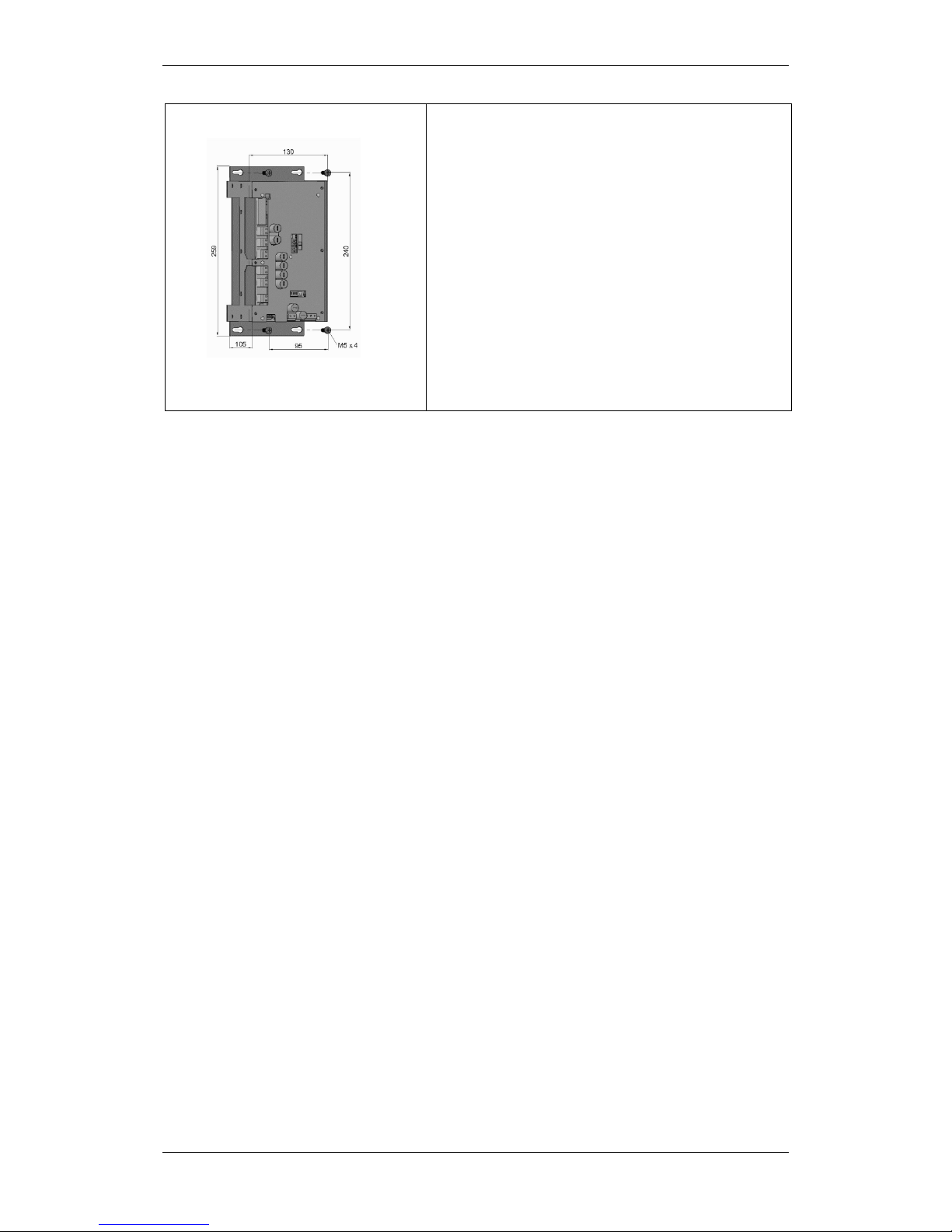
5.7 Mounting Power Supply Unit BPS-405 / BPS-410
The unit can be mounted inside a rack or consol. The hole and screw
dimensions are shown below.
Note that the BPS-410 Power Supply Unit 24VDC/10A is delivered as
two separate part numbers:
116-BPS-410 for 230VAC
116-BPS-410/115 for 115VAC
The dipswitch settings on the Power Board BSF-400 (dipswitch S6-6)
determines the type of power unit.
Dip-switch
Name
Description
S6-6
Power Unit Type
ON: BPS-405
OFF: BPS-410
For further information on dipswitch settings, refer to Appendix B –
Power Supply. Note that when using Power Unit BPS-410 (including a
24V/10A power supply), a calibration procedure must be performed.
Refer to the Commissioning Handbook, Calibration Procedure –
Power Unit BPS-410.

Mounting Instructions
Installation Handbook, AutroSafe Interactive Fire Detection System, Release 4, 116-P-ASAFE-INSTALL/DGB Rev. I, 2014-04-01,
Autronica Fire and Security AS
Page 25
5.8 Inserting Text Foils
Find the text foils in the
relevant language for the
panel in question (foil sheets
are delivered with the panel).
The part numbers are
indicated below.
Make sure that you are holding the textfoil the correct way.
Bend the small flap towards the panel (as shown on the left most
illustation below), then insert the foil into the appropriate slot, and
slightly push it in as far as possible.
The foils that are to be inserted into the slot on the righ hand side
of the panel front have a small flap which can easily be bent (along
the perforation holes).
Fire Alarm Control Panel BS-420 is shown in the example below.
E-2853
E-2852
E-2854
E-2855
E-2852
E-2856
E-2856
Example: Foil sheet for BS-420

Mounting Instructions
Installation Handbook, AutroSafe Interactive Fire Detection System, Release 4, 116-P-ASAFE-INSTALL/DGB Rev. I, 2014-04-01,
Autronica Fire and Security AS
Page 26
5.9 Cable Inlets / Outlets
When feeding the cables, use whichever is appropriate.
ø29 x 5
ø23 x 6
The illustration above shows the positioning and dimensions of the
cable inlets for BS-420/BC-420 (the uppermost illustration) and
BU-BV-420.

Mounting Instructions
Installation Handbook, AutroSafe Interactive Fire Detection System, Release 4, 116-P-ASAFE-INSTALL/DGB Rev. I, 2014-04-01,
Autronica Fire and Security AS
Page 27
5.10 Cut Out Dimensions for Flus h M oun tin g in a Wall
The Repeater Panel BU-BV-420 and Operator Panel BS-430 can be
flush mounted in a wall.
5.10.1 Repeater Panel BU-BV-420
The illustration below shows the cabinet’s cut out dimensions. The
dimensions given include space for the cover frame.
85

Mounting Instructions
Installation Handbook, AutroSafe Interactive Fire Detection System, Release 4, 116-P-ASAFE-INSTALL/DGB Rev. I, 2014-04-01,
Autronica Fire and Security AS
Page 28
5.10.2 Operator Panel BS-430
The illustration below shows the cabinet’s cut out dimensions. The
dimensions given include space for the cover frame.
85

Power Consumption
Installation Handbook, AutroSafe Interactive Fire Detection System, Release 4, 116-P-ASAFE-INSTALL/DGB Rev. I, 2014-04-01,
Autronica Fire and Security AS
Page 29
6. Power Consumption
6.1 Mains Power
6.1.1 BPS-405
The current consumption at 115V AC is 3,2 A.
The current consumption at 230V AC is 1,6A.
The inrush peak current consumption is 35A.
6.1.2 BPS-410
The current consumption at 115V AC is 4,5A.
The current consumption at 230V AC is 1,9A.
The inrush peak current consumption is 35A.
6.2 System Units
System Unit
Current Consumption
Fire Alarm Control Panel BS-420
Controller BC-420
156mA/27V DC (idle)
Max. 340mA/27V DC
Repeater Panel BU-BV-420
156mA/22,2V DC (idle)
Max. 220mA/27V DC (lamp test)
Operator Panel BS-430
175mA/27V DC (idle)
Max. 340mA/27V DC (lamp test)
Power Board BSF-400
85mA
6.3 Loop Units
For information on the current consumption for various loop units,
refer to technical specifications provided in the relevant datasheets.

Power Consumption
Installation Handbook, AutroSafe Interactive Fire Detection System, Release 4, 116-P-ASAFE-INSTALL/DGB Rev. I, 2014-04-01,
Autronica Fire and Security AS
Page 30
6.4 Phoenix Ethernet Switches
A network solution (AutroNet) with more than two panels requires the
use of switches, unless AutroNet Ring Topology is used (refer to
chapter 9.5.3). Only Phoenix Ethernet switches are approved and
supported by Autronica Fire and Security AS. The switch type and the
number of switches depend on the actual installation / network design
(number of panels and the transmission length between the panels /
switches).
For detailed technical information on the power consumption for
Phoenix Ethernet Switches, refer to System Description, AutroSafe
Interactive Fire Detection System.
6.5 Power Design Considerations
The Power Cabinet’s (BP-405) power supply (BPS-405) has 3A
available, as 2A is reserved for battery charging.
The supplies have three different output classes:
A1/A2, rated 2A each. (May be paralleled for higher current). Will
always be ON except in fault situations.
B1/B2, rated 2A each. (May be paralleled for higher current)
C1/C2, rated 2A each. (Cannot be paralleled. Will be turned OFF
during every start-up/initialization.
Output class A1 may be paralleled with A2, and output class B1 may
be paralleled with B2.
The outputs current is limited by the total available current, i.e. on a
BP-405 Power Cabinet with battery, 2A is drawn from output A1, only
1A is available from output A2, and nothing available for the other
outputs.
One BPS-405 unit can be connected to one battery set. A battery set
may NOT be shared by several BPS-405 units.
The outputs from different BPS-405 units cannot be paralleled, as the
power supplies are not designed for this. Earth fail detection will also
fail. Regulations define that battery resistance shall be monitored,
which prevents the use of common battery bank.
The A1/A2 outputs are n ot af fected of a BPS-405 software failure. If
one output (for example, A1) is short-circuited, the other ones are not
affected. This does not apply when two outputs are paralleled, (for
example, A1 and A2), as a short circuit in this case will disconnect
both outputs.

Cable Connection Overview
Installation Handbook, AutroSafe Interactive Fire Detection System, Release 4, 116-P-ASAFE-INSTALL/DGB Rev. I, 2014-04-01,
Autronica Fire and Security AS
Page 31
7. Cable Connection Overview
+
-
C1
+
-
C2
+
-
B1
+
-
B2
+
-
A1
+
-
A2
+
-
4
+
-
J18
3
2
1
BSA-400
+
-
4
+
-
3
2
1
Module
8
7
6
5
10
9
Power Board
5
6
7
8
1
2
3
4
AFB A
AFB A''
AFB CT A
AFB Earth Fault Sense
AFB B
AFB B''
AFB CT B
AFB Earth Fault Sense
+
-
Batt
+
-
1 2 3
13
15
17
19
5
7
9
11
1
3
14
16
18
20
6
8
10
12
2
4
TERMINAL
BLOCK
Cat.5
--
++
12V 12V
Power Cabinet
BP-405
Fire Alarm
Control Panel
Controller Board
Power Supply
BS-420
BSF-400
BSS-310A
BSS-310A /
BSS-311
The cable connection overview
shows a redundant 24V cabling
between BSA-400 and BSF -400,
which is required for cabling
between two different cabinets.
If the 24V cabling is inside the same
cabinet, redundant cabling is not
required. Single cabling is thus
possible (for example, between
A1+/- and J18/1 / J18/ 2).

Connecting Internal Cables
Installation Handbook, AutroSafe Interactive Fire Detection System, Release 4, 116-P-ASAFE-INSTALL/DGB Rev. I, 2014-04-01,
Autronica Fire and Security AS
Page 32
8. Connecting Internal Cables
8.1 Overview – BS-420 / BC-420
Multifunction cable
XGE-1/20-40
AL_Com+ cable
XGE-1/10-50

Connecting Internal Cables
Installation Handbook, AutroSafe Interactive Fire Detection System, Release 4, 116-P-ASAFE-INSTALL/DGB Rev. I, 2014-04-01,
Autronica Fire and Security AS
Page 33
8.2 BS-420 / BC-420
8.2.1 AL_Com+ Connection on Controller Board BSA-400
8.2.2 AL_Com+ Connection on Communication Module BSL-310
Connector J5
Cable XGE-1/10-50
Cable XGE-1/10-50

Connecting Internal Cables
Installation Handbook, AutroSafe Interactive Fire Detection System, Release 4, 116-P-ASAFE-INSTALL/DGB Rev. I, 2014-04-01,
Autronica Fire and Security AS
Page 34
8.2.3 Multifunction Serial Port Connection on Controller Board BSA-400
A ribbon cable is connected between the Multifunction Serial Port
Connector and the main terminal block (mounted on the DIN rail inside
the cabinet).
8.2.4 Multifunction Serial Port Connection on Terminal Block, List L1
The ribbon cable from the Serial Port Connection on the Controller
Board is connected to the main terminal block, list L1 (mounted on the
DIN rail inside the cabinet).
Connector J3
Multifunction cable XGE-1/20-40
Multifunction cable
XGE-1/20-40

Connecting Internal Cables
Installation Handbook, AutroSafe Interactive Fire Detection System, Release 4, 116-P-ASAFE-INSTALL/DGB Rev. I, 2014-04-01,
Autronica Fire and Security AS
Page 35
8.2.5 Multifunction Serial Port Connection Overview – BSA-400
Connection to
terminal block
(L1)
Description
Connector J3 on Controller
Board BSA-400
L1.1
GND
J3.1
L1.2
GND
J3.2
L1.3
AutroFieldBus B
J3.3
L1.4
Multifunction Serial Port RS-422/RS485 A+
J3.4
L1.5
AutroFieldBus B’
J3.5
L1.6
Multifunction Serial Port RS-422/RS485 B-
J3.6
L1.7
AutroFieldBus B Reference
J3.7
L1.8
Multifunction Serial Port RS-422 X+
J3.8
L1.9
AutroFieldBus A
J3.9
L1.10
Multifunction Serial Port RS-422 Z+
J3.10
L1.11
AutroFieldBus A’
J3.11
L1.12
Multifunction Serial Port RS-232 TX
J3.12
L1.13
AutroFieldBus A Reference
J3.13
L1.14
Multifunction Serial Port RS-232 RX
J3. 14
L1.15
GND
J3.15
L1.16
Multifunction Serial Port Reference
J3.16
L1.17
Fault Relay Normal Open
J3.17
L1.18
GND
J3.18
L1.19
Fault Relay Normal Closed
J3.19
L1.20
Fault Relay Common
J3.20
8.3 BC-440
For information on the cabling to AutroSafe Controller Rack BC-440,
refer to separate datasheet.

Connecting Internal Cables
Installation Handbook, AutroSafe Interactive Fire Detection System, Release 4, 116-P-ASAFE-INSTALL/DGB Rev. I, 2014-04-01,
Autronica Fire and Security AS
Page 36
8.4 Internal Earth Cabling

Connecting External Cables
Installation Handbook, AutroSafe Interactive Fire Detection System, Release 4, 116-P-ASAFE-INSTALL/DGB Rev. I, 2014-04-01,
Autronica Fire and Security AS
Page 37
9. Connecting External Cables
9.1 Introduction
This chapter deals with the connection of external cables.
For more detailed information regarding the Controller Board BSA-400
and Power Board BSF-400, see Appendix.
9.2 Before Connecting Cables
Before connecting cables, make sure that the mains power is not
connected.
Remove fuse F8 from the power supply in all Power Cabinets.
Do not replace the fuse until commissioning of the system. Refer to
the Commissioning Handbook.
POWER OFF!
9.3 Mains Wiring - Two-pole Disconnect Device
In the fixed mains wiring to the panel a two-pole disconnect device
must be provided to disconnect the equipment from the power supply
when servicing is required. Normally, this switch is a two-pole
automatic fuse located in the fuse terminal box at the premises. This
fuse location must be marked "Fire Alarm System". No other than the
Fire Detection System shall be sourced from this switch.
The isolation of the mains wiring must be of either:
inflammability class V2
or
the wiring has to be fixed to the cabinet separated from all other
cables
!

Connecting External Cables
Installation Handbook, AutroSafe Interactive Fire Detection System, Release 4, 116-P-ASAFE-INSTALL/DGB Rev. I, 2014-04-01,
Autronica Fire and Security AS
Page 38
9.3.1 Voltage Selection 115/230VAC on the BPS-405
Make sure that the mains power is not connected.
Use a screwdriver to slide the switch to the correct position
according to the appropriate voltage (115/230VAC).
9.3.2 115/230VAC Voltage BPS-410
Note:
The BPS-410 Power Unit 24VDC/10A is delivered as two separate
part numbers:
116-BPS-410 for 230VAC
116-BPS-410/115 for 115VAC
Make sure to use the correct unit according to the appropriate
voltage (115/230VAC).
!
POWER OFF!
!
POWER OFF!
Connecting External Cables
Installation Handbook, AutroSafe Interactive Fire Detection System, Release 4, 116-P-ASAFE-INSTALL/DGB Rev. I, 2014-04-01,
Autronica Fire and Security AS
Page 39
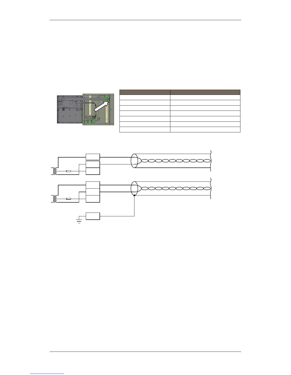
9.4 AutroFieldBus Con nections
9.4.1 Connections to BS-420/BC-420 - Terminal Block (List 1)
Shielded cable required.
Terminal
Function
L1.9
AutroFieldBus A
L1.11
AutroFieldBus A’
L1.13
AutroFieldBus CT A
L1.3
AutroFieldBus B
L1.5
AutroFieldBus B’
L1.7
AutroFieldBus CT B
L1.15
Earth
L1.3
L1.5
L1.7
L1.15
L1.9
L1.11
L1.13
Last AFB unit
First AFB unit
Terminal block L1 with shielded AutroFieldBus cable
AFB
AFB A

Connecting External Cables
Installation Handbook, AutroSafe Interactive Fire Detection System, Release 4, 116-P-ASAFE-INSTALL/DGB Rev. I, 2014-04-01,
Autronica Fire and Security AS
Page 40
9.4.2 Connections to Connector J2, Power Board BSF-400
9.4.3 Example of the Interconnection of Several Power Cabinets
The example below shows the interconnection of two Po wer Cab ine ts
on the AutroFieldBus. Note that the AutroFieldBus always goes from
AFB A on the main terminal block inside BS-420/BC-420 to AFB B on
the J2 connector on the Power Board BSF-400, then from AFB A to
the next unit. The cable finally returns to AFB B on the main terminal
block.
A
B
Fire Alarm Control
Panel BS
-420 /
Controller BC-420
/
BC-
440
B
A
B
A
Power Cabinet
BP-
405
(Power Board
BSF-400)
L
1.9
L
1.
11
L1.3 L1.5
J2
.5
J2.
6
J2.
1
J
2.2
J2.
5
J
2.6
J2.1
J
2.2
1
2
3
AFB A
AFB A"
AFB CT A
4
5
6
AFB Earth Fault Sense
AFB B
AFB B"
78AFB CT B
AFB Earth Fault Sense
J2
J26
1 6
1
2
3
Alarm NO
Alarm Com
RC (Remote test)
4
5
6
Fault Relay NO
Fault Relay NC
Fault Relay Com
F1 A1 F2AL
F2 A2 F2AL
J19
S1 Reset
0V
+
A1
S5
AFB Earth Fault Off
AFB Earth Fault On
1
OFF
ON
2
OFF
ON
J2

Connecting External Cables
Installation Handbook, AutroSafe Interactive Fire Detection System, Release 4, 116-P-ASAFE-INSTALL/DGB Rev. I, 2014-04-01,
Autronica Fire and Security AS
Page 41
9.5 Connection of Netw ork Cables (AutroNet)
Each panel provides two ports; Ethernet 1 and Ethernet 2. Autr oNet
consists of one of the following network topologies:
AutroNet Redundant Star Topology
AutroNet Single Star Topology
AutroNet Ring Topology
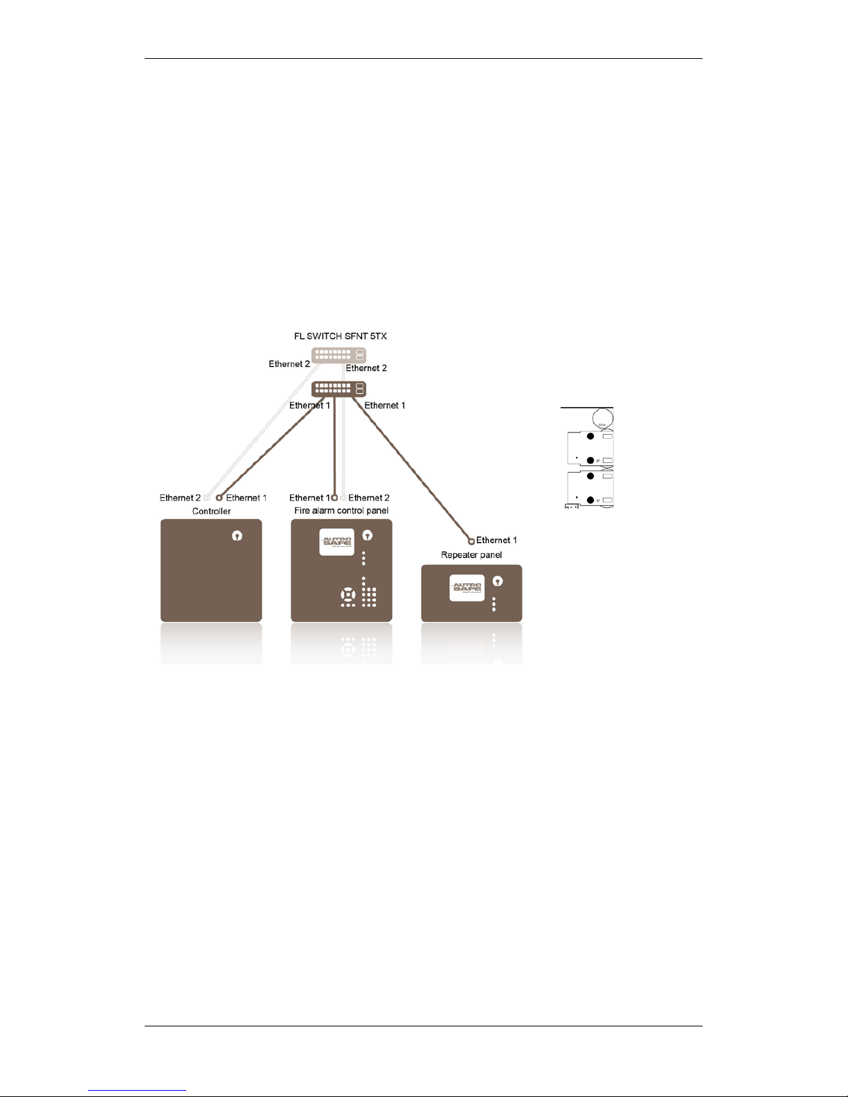
9.5.1 AutroNet Redundant Star Topology
The illustration below shows an example of the fully redundant
standard AutroNet, where the following guidelines apply:
Connect the Ethernet cables for Ethernet 1 to and from the
connections labeled Ethernet 1 (panels and Ethernet switches)
throughout the entire system.
Connect the Ethernet cables for Ethernet 2 to and from the
connections labeled Ethernet 2 (panels and Ethernet switches)
throughout the entire system.
Ethernet 1
Ethernet 2
Ethernet ports on
Controller Board
BSA-400
Connecting External Cables
Installation Handbook, AutroSafe Interactive Fire Detection System, Release 4, 116-P-ASAFE-INSTALL/DGB Rev. I, 2014-04-01,
Autronica Fire and Security AS
Page 42
9.5.2 AutroNet Single Star Topology
As an option, AutroSafe 4 allows also single Ethernet connections to
one or several panels in a system if redundancy is not required.
Ethernet 1 must always be used for single Ethernet connections.
The example below is similar to the one in the previous chapter; all
panels have redundant connections to the system, except for the
Repeater Panel, which has a single Ethernet connection.
Between the Repeater Panel and the Ethernet switch, make only a
single Ethernet connection to and from Ethernet 1.
Connect the remaining Ethernet cables as described in the
previous chapter
Ethernet 1
For single Ethernet connections,
always use Ethernet port 1
Connecting External Cables
Installation Handbook, AutroSafe Interactive Fire Detection System, Release 4, 116-P-ASAFE-INSTALL/DGB Rev. I, 2014-04-01,
Autronica Fire and Security AS
Page 43
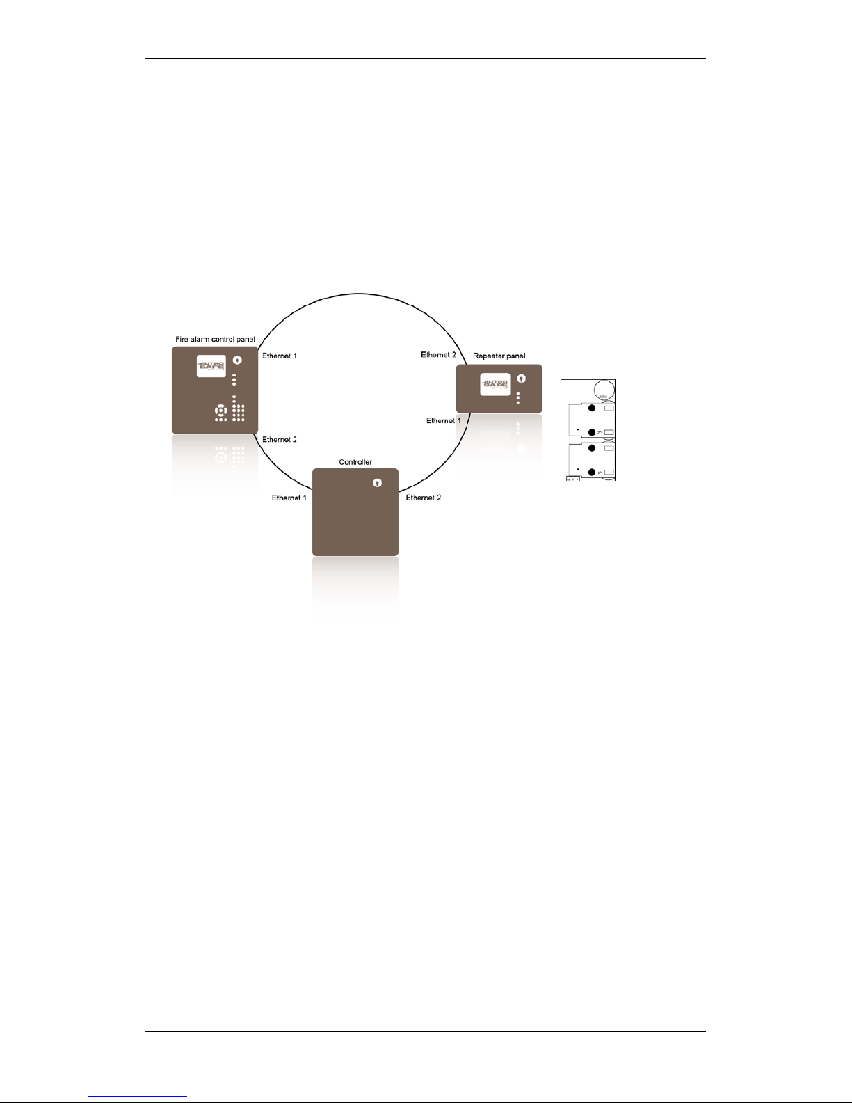
9.5.3 AutroNet Ring Topology
In an AutroNet Ring Topology all panels are connected to each other
forming a closed loop. The first panel is connected to the second, the
second is connected to the third, and so on (preferably from Ethernet
1 to Ethernet 2, from Ethernet 1 to Ethernet 2, from Ethernet 1 to
Ethernet 2 and so on).
A ring topology is a redundant network, as all panels will continue to
operate even with a single break or short-circuit on the ring.
Ethernet ports on
Controller Board
BSA-400
Ethernet 1
Ethernet 2

Connecting External Cables
Installation Handbook, AutroSafe Interactive Fire Detection System, Release 4, 116-P-ASAFE-INSTALL/DGB Rev. I, 2014-04-01,
Autronica Fire and Security AS
Page 44
9.5.4 Connection to Controller Board BSA-400
18
1 2
The BSA-400 board on all panels provides two separate 10/100Mbit
Ethernet ports. The connector is an RJ-45 modular jack, suitable for
shielded cable CAT5 which allows cable lengths up to 100m.
LED 1
Activity LED
LED 2
If ON, 100MBit/s, if OFF, 10MBit/s
9.5.5 Common Earth Connections
All panels must be connected to a common earth for EMC
compliance.
2 x 2
24V
Fire Alarm
Control Panel
BS-420
Controller
BC-420 / BC-440
Power Cabinet
BP-405
BU-BV-420
BU-BV-420
Operator
Panel
BS-430
2 x 2
24V
Shielded or armoured cable must be used for the 24V DC power
supply.

Connecting External Cables
Installation Handbook, AutroSafe Interactive Fire Detection System, Release 4, 116-P-ASAFE-INSTALL/DGB Rev. I, 2014-04-01,
Autronica Fire and Security AS
Page 45
9.6 RS-485 Connections to Terminal Block, List L1
Twisted pair, shielded cable is required.
Maximum 100Ω resistive loss.
Maximum total length 1200m.
Maximum cable capacitance 150 nF.
L1.4
L1.6
L1.16
RS-422/RS485 A+
RS-422/RS485 BSerial Reference
RS485 A+
RS485 BSerial Reference
Terminal block list L1
RS-485
9.7 RS-422 Connections to Terminal Block, List L1
L1.4
L1.6
L1.8
L1.10
L1.16
RS-422/RS485 A+
RS-422/RS485 BRS-422 X+
RS-422 ZSerial Reference
RS-422 A+
RS-422 BRS-422 X+
RS-422 ZSerial Reference
Terminal block list L1
RS-422
Schematic of port equivalent:
TX_422_X+
Isolation
TX_422_Z-
RX_422_A+
RX_422_B-
Signal Reference
+5v_SER_0
8
10
4
6
16
The protection shown in the schematic of port equivalent above is
made for 1kV High Energy Surge. In addition, the connection is
protected against wrong connections between Serial Reference and
other signals (X->Signal ref, Z->Signal ref, A->Signal ref, B->Signal
ref) for voltage up to 29V DC.

Connecting External Cables
Installation Handbook, AutroSafe Interactive Fire Detection System, Release 4, 116-P-ASAFE-INSTALL/DGB Rev. I, 2014-04-01,
Autronica Fire and Security AS
Page 46
9.8 RS-232 Connections to Terminal Block, List L1
L1.12
L1.14
L1.16
RS-232 TX
RS-232 RX
Serial Reference
Terminal block list L1
RS-232
RS-232 TX
RS-232 RX
Serial Reference
9.9 24V Power Connections
9.9.1 Connections to Controller Board BSA-400
24V power is supplied to connector J18 on the Controller Board
BSA-400 on all panels.
Redundant cabling:
Connector J18 on
Controller Board BSA-400
Description
Connections to Power Board BSF400
J18.1
+24V In 1
Interconnection
A1 +
J18.2
0V In 1
A1 0V
J18.3
+24V In 2
A2 +
J18.4
0V In 2
A2 0V
Single cabling:
Connector J18 on
Controller Board BSA-400
Description
Connections to Power Board BSF400
J18.1
+24V In 1
Interconnection
A1 +
J18.2
0V In 1
A1 0V
J18.3
+24V In 2
A1 +
J18.4
0V In 2
A1 0V
From Power Board BSF-400
J18

Connecting External Cables
Installation Handbook, AutroSafe Interactive Fire Detection System, Release 4, 116-P-ASAFE-INSTALL/DGB Rev. I, 2014-04-01,
Autronica Fire and Security AS
Page 47
9.9.2 Connections to Power Board BSF-400
Output
Connections to
BSF-400
Description Intended to be used for:
A1
J19
+24V DC / 2A
0V
Monitored panel equipment.
A2
J18
+24V DC / 2A
0V
Monitored panel equipment.
B1
J24
+24V DC / 2A
0V
External equipment.
B2
J23
+24V DC / 2A
0V
External equipment.
C1
J22
+24V DC / 2A
0V
External equipment. 3 seconds break at initialization of
panel.
C2
J21
+24V DC / 2A
0V
External equipment. 3 seconds break at initialization of
panel.
F1
A1 F2AL
F2
A2 F2AL
J19
S1 Reset
High Low
8
7
6
Internal Fault
General Fault
Battery Fault
5
43Fuse Fault
2
1
Mains Fault
Power ON
J24
J23
J22
0V
C2
J21
F2AL
F3 B1
F2AL
F4
B2
F2AL
F5
C1
F2AL
F6 C2
AFB Adress (H & L)
1
2
3
Earth Fault Sense ON/OFF
Battery relay (see manual)
AFB present
4
5
6
Battery present
61
S6
ON
OFF
source (see manual)
S2, Start on standby
15
5
4
3
2
1
Therm.+
Therm.PSF
-V
Vcon
+
-
BATT
J20
J17
F7 Battery
F8 Charger
1 2 3
Charger +24V
Charger 0V
Earth
J25
E-2868
J18
+
0V
+
C1
0V
+
B2
0V
+
B1
0V
+
A2
0V
+
A1
X11 X10
AFB Com
BP-410/01
BP-405/01
T10T5T10
T5
F7 F8
AH AH
AH AH

Connecting External Cables
Installation Handbook, AutroSafe Interactive Fire Detection System, Release 4, 116-P-ASAFE-INSTALL/DGB Rev. I, 2014-04-01,
Autronica Fire and Security AS
Page 48
9.9.3 Power Connection Overview
BSS-311 is required when redundant connection is used.
+
+
4
3
2
1
-
+
+
4
3
2
1
J18
BSA-400
BSS-310A
(BSS-311)
+
+
24VDC
24VDC
Ethernet
switch
Ethernet
switch
Fire Alarm Control P anel BS-420 /
Controller BC-420
+
+
4
3
2
1
J18
BSA-400
BU-BV-420
BS-430
Information/Repeater Panels
+
-
A1
+
-
B2
+
-
A2
+
-
B1
+
-
C2
+
-
C1
BU-BV-420
BU-BV-420
BU-BV-420
Power Cabinet B P-405
Outputs
2 x 24VDC/2A
Outputs
2 x 24VDC/2A
w/interrupt
at init ializat ion
of panel.
Outputs
2 x 24VDC/2A
Power Board
BSF-400
1
2
3
4
Batt
+ -
Batt
24V
Charger
1 2 3
+ -
Charger
connection
Pow er to t h ird par ty
equipment with input
voltage 18 – 32VDC
24VDC/2A
24VDC/2A
------ Connected if needed.
*
* External panels type BU-BV-420 and BS-430
can be connected both to output A and B.
De vi de total power to bot h A an d B.

Connecting External Cables
Installation Handbook, AutroSafe Interactive Fire Detection System, Release 4, 116-P-ASAFE-INSTALL/DGB Rev. I, 2014-04-01,
Autronica Fire and Security AS
Page 49
9.10 Mains Power Connections
Power must not be applied before commissioning, refer to
Commissioning Handbook.
When applying power during commissioning, always connect t he
cables to the batteries in the Power Cabinet BP-405 first, then power
up the system shortl y afterwar ds by connecting the mains cable to a
mains socket (230V/115V AC) or by switching the power ON from an
external main fuse box.
The connection of mains power (AC) to the Power Cabinet BP-40 5 is
shown below. Note that the isolation must be kept on the mains cable
as close up to the terminal points (L, N and ) as possible.
!
POWER OFF!
L
N

Installing I/O Modules
Installation Handbook, AutroSafe Interactive Fire Detection System, Release 4, 116-P-ASAFE-INSTALL/DGB Rev. I, 2014-04-01,
Autronica Fire and Security AS
Page 50
10. Installing I/O Modules
10.1 Introduction
This chapter provides information on the mounting and removal of I/O
modules.
Note that the internal Power Module (BSS-310A) and the
Communication Module (BSL-310) are already mounted in a fixed
position when the product leaves the factory.
10.2 Front View of I/O Module
Screw
terminal 1
Front view when mounted on rail
Screw
terminal 10

Installing I/O Modules
Installation Handbook, AutroSafe Interactive Fire Detection System, Release 4, 116-P-ASAFE-INSTALL/DGB Rev. I, 2014-04-01,
Autronica Fire and Security AS
Page 51
10.3 Mounting / Removing I/O Modules
10.3.1 General
Note: The Power Module (BSS-310A)
must always be mounted first on the
rail - at the bottom - before any other
modules. The Communication Module
(BSL-310) is then mounted on top of
the Power Module. If the optional Dual
Power Monitoring Module BSS-311 is
to be used, this module always has to
be mounted at the bottom – before
BSS-310A and BSL-310.
All other modules can be mounted in
arbitrary order on top of these
modules.
10.3.2 Mounting
The connection block on the I/O module must be pointing to the right
when the module is to be inserted in a BS-420/BC-420 cabinet.
Snap the right side of the
fastener onto the mounting
rail (1), then press the module
slightly inwards (2) until the
left side fastens.
Then, carefully press the
module downwards as far
as possible. Make sure that the module is properly connected to
the module below.
Note! Make sure the mains power is OFF!
Fixed Pos ition
BSL-310
BSS-310A
(BSS-311, optional)
When the system is to be configured at a later p o int, note that the
AutroSafe Configuration Tool graphically shows the first module on
the top of the figure and the following in desc ending order. This
may be opposite to the physical mounting, and must be taken into
consideration when configuring the sys tem. Also note that the
configuration tool does not show the BSS-311 and BSL-310.

Installing I/O Modules
Installation Handbook, AutroSafe Interactive Fire Detection System, Release 4, 116-P-ASAFE-INSTALL/DGB Rev. I, 2014-04-01,
Autronica Fire and Security AS
Page 52
10.3.3 Removing
Ensure the panel is not powered.
Unplug the connection block.
Use a screwdriver to carefully
lift the topmost module upwards
(1) until the connector between the
modules is free.
Use the screwdriver to slightly
bend the left side of the
fastener towards left (2) until
it loosens, then remove (3) the
module.
If necessary, continue removing
the next one in the same way.
10.3.4 Before Connecting Cables
Before connecting cables, make sure that the mains power is not
connected.
POWER OFF!
10.4 Data Sheets - I/O Modules
The AutroSafe User Documentation provides data sheets for I/O
modules, including a short description of the I/O module, its
application, plus technical specifications and cabling.
!

Dual Safety Installation
Installation Handbook, AutroSafe Interactive Fire Detection System, Release 4, 116-P-ASAFE-INSTALL/DGB Rev. I, 2014-04-01,
Autronica Fire and Security AS
Page 53
11. Dual Safety Installation
11.1 Dual Safety System Overview
An AutroSafe system using the Dual Safety concept consists of a
Primary System and a Secondary System. The purpose of the
concept is to ensure that the Secondary System takes over the control
of the detection loops if the Primary System or parts of it is lost for any
reason.
To achieve this, the redundant loop control interface AutroKeeper
BN-180 is required.
An AutroMaster can communicate with both the Primary and
Secondary System via AutroCom.
The connections that are to be used between the Primary/Secondary
System and the detection loops depend on distances and the number
of Loop Driver Modules/detection loops used.
11.2 Rules of Thumb
Note that these rules of thumb goes for both systems in a Dual Safety
configuration:
Up to 6 Loop Driver Modules can be connected to one I/O stack
Up to 12 Loop Driver Modules can be connected to one panel
Up to 6 Loop Driver Modules can be connected to one panel
directly (one I/O stack) if the cable length between the panel’s main
board AL_Com+ port and the I/O stack is less than 3 meters.
Up to 12 Loop Driver Modules can be connected to one panel
through AutroFieldBus (up to 12 I/O stacks). This solution has to
be used if the cable length between the panel’s main board and the
I/O stack exceeds 3 meters, but can also be used for cable lengths
less than 3 meters.

Dual Safety Installation
Installation Handbook, AutroSafe Interactive Fire Detection System, Release 4, 116-P-ASAFE-INSTALL/DGB Rev. I, 2014-04-01,
Autronica Fire and Security AS
Page 54
11.2.1 Example 1: Connections Using AL_Com+ only
The distance from the Primary Panel to the Loop Driver Module is less
than 3 meters. An AL_Com+ flat ribbon cable is used between the
panel AL_Com port and the I/O stack (including the Loop Driver
Module).
The distance from the Secondary Panel to the Secondary Loop Dri ver
Module is less than 3 meters. An AL_Com+ flat ribbon cable is used
between the panel AL_Com port and the I/O stack (including the
Secondary Loop Driver Module).

Dual Safety Installation
Installation Handbook, AutroSafe Interactive Fire Detection System, Release 4, 116-P-ASAFE-INSTALL/DGB Rev. I, 2014-04-01,
Autronica Fire and Security AS
Page 55
11.2.2 Example 2: Connections using both AL_Com+ and AutroFieldBus
The distance from the Primary Panel to the Primary Loop Driver
Module is less than 3 meters. An AL_Com+ flat ribbon cable is used
between the panel AL_Com port and the I/O stack (including the Loop
Driver Module).
The distance from the Secondary Panel to the Secondary Loop Dri ver
Module is more than 3 meters. An AL_Com+ flat ribbon cable
(maximum 3 meters) is used between the AutroFieldBus (AFB)
Protocol Converter BSD-321 and the I/O stack (including the
Secondary Loop Driver Module). The AFB Protocol Converter is
connected to the panel’s AFB. The AFB cable length can be up to
1000 meters. Booster equipment can be added to exceed the AFB
cable length even further.
11.3 Connections Overview
There are two AutroKeepers BN-180 for each detection loop in a Dual
Safety System (see next page). One must be assigned to the Primary
System and the other to the Secondary System. The BSD-321 (if
used) must be set to the Al_Com+ protocol (default).
The AutroKeeper is physically placed between the loop controller
(BSD-310) and the detection loop (one belonging to the Primary
System and one belon gi ng to the Secondary System) and thus
controlling/providing the loop controller access to the detection loop.

Dual Safety Installation
Installation Handbook, AutroSafe Interactive Fire Detection System, Release 4, 116-P-ASAFE-INSTALL/DGB Rev. I, 2014-04-01,
Autronica Fire and Security AS
Page 56
-2
+1
-5
+4
OUT
IN
Loop Driver Module
BSD-310
-10
+9
-12
+11
OUT
IN
IN
OUT
-16
+15
-14
+13
1 2
3
1 2
3
2 1
3
2
1
3
IN
OUT
- 12
+11
-10
+9
-14
+13
-16
+15
OUT
IN
Loop Driver Module
BSD-310
-5
+4
-2
+1
IN
OUT
AutroKeeper
BN-180
AutroKeeper
BN-180
Communication Module
BSL-310
3 TX
7
R
X
10 GND
9 CTS
1 INT
Termination
Block
AutroFieldBus
Protocol Converter
BSD-321
25 TX Port 0
26 RX Port 0
27 GND Port 0
13 TX Port 1
14 RX Port 1
15 GND Port 1
16 IE Port 1
28 IE Port 0
AF
B
A 9
AFB A’ 11
AFB B 3
AFB B’ 5
5 A
FB B
6 AFB B’
1 AFB A
2 AFB A’
Termination
Block
Fire Alarm Control Panel
BS-420
Fire Alarm Control Panel
BS-420
Primary System Secondary System
3 TX
7 RX
10 GND
9 CTS
1 INT
BN-180 as Active BN-180 as Standby
Patented component to meet
the new SOLAS requirement

Dual Safety Installation
Installation Handbook, AutroSafe Interactive Fire Detection System, Release 4, 116-P-ASAFE-INSTALL/DGB Rev. I, 2014-04-01,
Autronica Fire and Security AS
Page 57
11.3.1 Connections – AutroKeeper BN-180
Pin
number
Description
1
TTL COM
Debug port (internal
use only)
2
TTL IN
Debug port (internal
use only)
3
TTL OUT
Debug port (internal
use only)
4
GND 5
24V IN
Power In (Green LED)
6
0V IN
Power In
7
FAILSAFE COM
FailSafe Rel. (future)
8
FAILSAFE NO
FailSafe Rel. (future)
9
OUTLOOP +
To “first” Loop Unit
10
OUTLOOP -
--“--
11
INLOOP +
To “last” Loop Unit
12
INLOOP -
--“--
13
OUT +
To Loop Driver’s IN +
14
OUT -
To Loop Driver’s IN -
15
IN +
To Loop Driver’s OUT+
16
IN -
To Loop Driver’s OUT -
DIN rail conn. 1
24V IN
Power In
DIN rail conn. 2
0V IN
Power In
DIN rail conn. 3
Not used
DIN rail conn. 4
Not used
DIN rail conn. 5
GND
11.3.2 Switch Settings – AutroKeeper BN-180
Dipswitch 1 determines whether the BN-180 in question is Primary or
Secondary.
Dip-
switch
Description (ON/OFF)
1
“Ascription” (use one of each):
Off – Primary / On – Secondary
2
Off – Normal operation (Seen as AL_Com
unit)
On – Force Majeur (If Ascription
Primary: Active, Secondary: Standby –
automatic actions disabled)
3
When switched to On or Off the unit will
be reset within 5 seconds

Cable Specifications
Installation Handbook, AutroSafe Interactive Fire Detection System, Release 4, 116-P-ASAFE-INSTALL/DGB Rev. I, 2014-04-01,
Autronica Fire and Security AS
Page 58
12. Cable Specifications
For the complete information on cable specifications, refer to Cable
Specifications, part number 116-P-ASIFGCABLESPEC/CGB
(file name: asafeifgcable_cgb).

Service and Maintenance
Installation Handbook, AutroSafe Interactive Fire Detection System, Release 4, 116-P-ASAFE-INSTALL/DGB Rev. I, 2014-04-01,
Autronica Fire and Security AS
Page 59
13. Service and Maintenance
The AutroSafe Interactive Fire Alarm System provides a Log Menu,
which records all system events, i.e. fire alarms, prealarms, faults,
enablements/disablements, user operations and tests.
It is the system owner’s or authorized personnel’s duty to register all
events in a Control Journal.
13.1.1 Monthly Maintenance
Step
Description
√
1
Look through the log journal to find any possible irregularities.
2
Make sure that possible changes in the building structure or storage environment have not
affected the detectors’ capability to detect a potential fire.
3
Make sure that the detectors are not covered with paint or contaminated with dust or dirt.
Check the log for contaminated detectors (Service/Log menu).
4
Perform a visual inspection of the panels/cabinet .
5
Perform a simple test of display and panel functions
6
Test the sounders.

Service and Maintenance
Installation Handbook, AutroSafe Interactive Fire Detection System, Release 4, 116-P-ASAFE-INSTALL/DGB Rev. I, 2014-04-01,
Autronica Fire and Security AS
Page 60
13.1.2 Annual Service and Maintenance
The whole system (control panel, detectors, control functions) should
be inspected annually. An annual service inspection comprises the
following:
Step
Description
√
1
To test the panel indicator lights and internal buzzer, press and hold the Reset button for at
least 5 seconds. All indicators are lit and the buzzer is turned on. The test will automatically
stop. The lamp test can be performed in access level 1 (no use of key).
2
Test all operating keys by pressing each key (refer also to Operator’s Handbook):
All buttons will give a short "Beep" when pressed, except Mute button, Menu button and
Reset System button (plus the ones that are not supported, see below).
Note that the left/right arrow buttons and the two buttons in the lowermost right hand corner
(indicated with a white line) are not yet supported:
‘
3
Perform a visual and functional inspection of manual call-points and automatic detectors.
Check the log for contaminated detectors (Service/Log menu).
4
Disable any alarm transference to the Fire Alarm Routing Equipment -FARE output.
5
Activate the alarm system. Test all sounders by activating an alarm from a corresponding
manual call-point.
6
Test all control functions.
7
Activate alarms from at least one detector/manu al call -point in each zone and a check that all
respective outputs are activated.
8
Test the action of any auxiliary operating functions (disabling, cancelling and resetting
buttons).
9
Check the alarm transference outputs by connecting from outgoing outputs (potential free
relay and 24V output) activated by alarm in a zone.
10
Check the fault warning function from detector zones by removing a detector in each zone.
Mute Panel button
Silence Alarms button
Reset System button
Menu button
Close Window button
Alphanumeric keyboard
Manoeuvre buttons

Service and Maintenance
Installation Handbook, AutroSafe Interactive Fire Detection System, Release 4, 116-P-ASAFE-INSTALL/DGB Rev. I, 2014-04-01,
Autronica Fire and Security AS
Page 61
Step
Description
√
Activate a fault (remove battery fuse) and observe:
- the Fault indicator starts to blink
- a fault warning is displayed
- the internal buzzer is turned ON
- the Fault Warning Routing Equipment (FWRE) output is activated (if any)
11
Verify all conditions, i.e.:
- Fire Alarm condition
- Fire Warning condition
- Fault Warning condition
- Disablement condition
- Test condition
12
On completion of checks, ensure that only the green "Power" indicator is ON when the panel
is in its idle state (normal operation).
13
Enable alarm transference to the Fire Alarm Routing Equipment -FARE output.
The battery should be changed every 4 years. If a fault arises on the
panel that cannot be rectified, contact your nearest Autronica Fire and
Security office for qualified assistance.
13.1.3 SIL2 Approved Systems
For SIL2 approved systems, service and maintenance shall be carried
out according to the proof test intervals stated on the
AutroSafe 4 Oil&Gas SIL2 (G2) certificate with registration num ber
44 207 11 555929-001.

Installation Handbook, AutroSafe Interactive Fire Detection System, Release 4, 116-P-ASAFE-INSTALL/DGB Rev. I, 2014-04-01,
Autronica Fire and Security AS
Page 62
14. Appendix A - Controller Board
BSA_400
14.1 Circuit Board Layout
Label on cover
To main Terminal Block. See
manual for connections
S6
RS-422
RS-485
1
OFF
ON
2
OFF
ON
3
OFF
ON
S7
RS-422 Termination
RS-485 Termination
1
ON
ON
2
OFF
ON
S3
AFB EARTH Fault Off
AFB EARTH Fault On
1
OFF
ON
2
OFF
ON
Serial
Console
Port
Push
Button
Reset
Ethernet 1
Ethernet
2
To BSL-310
0V 2 IN
24V 2 IN
0V 1 IN
24V 1 IN
4
3
2
1
To Front Panel
Panel ID
Network ID
USB OTG
2 x USB Host
LCD Backlight
Panel Type
To LCD
J2
J1
J14
J5
J18
E-2878
J3
S6
S7
J21
S5
J9
J16
S3
X6
X4
X5
X3
J17
J13
J12
J2
J1
J14
J5
J18
J3
J10
J11
S2
S6
S7
S2
ON
OFF
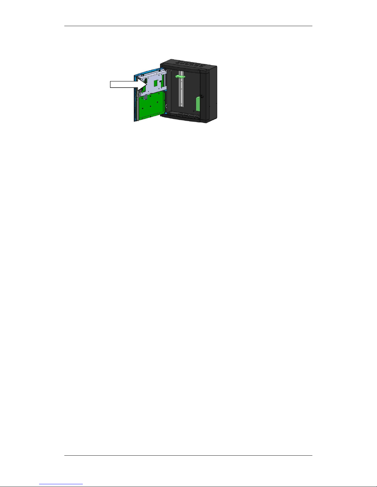
Appendix A - Controller Board BSA_400
Installation Handbook, AutroSafe Interactive Fire Detection System, Release 4, 116-P-ASAFE-INSTALL/DGB Rev. I, 2014-04-01,
Autronica Fire and Security AS
Page 63
14.2 Location inside Fire Alarm Control Panel BS-420
14.3 Description
The Controller Board BSA-400 is the main CPU which controls all
system functionality.
The system offers the following comm unication por ts:
2 Ethernet ports for AutroNet and/or AutroCom, plus downloading
of configuration data and system software
1 AL_Com+ interface (loop communication)
1 RS-232, RS-422 or RS-485 serial port for communication with
third party equipment (AutroCom /ESPA4.4.4/MODBUS/VDR)
1 AutroFieldBus (AFB) interface
2 USB host ports for the connection of a printer and for the
connection of a memory stick for downloading configuration data
and system software
Interface for the connection of display and front board
FailSafe relay output
BSA-400
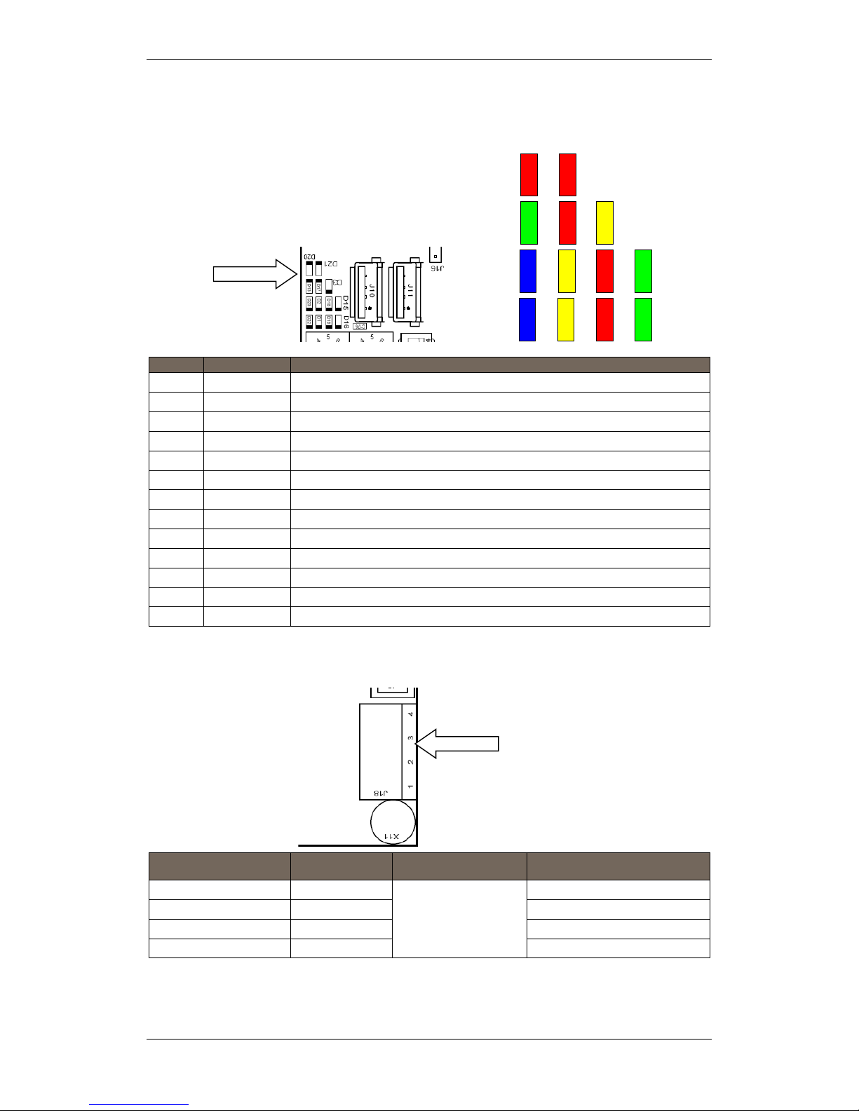
Appendix A - Controller Board BSA_400
Installation Handbook, AutroSafe Interactive Fire Detection System, Release 4, 116-P-ASAFE-INSTALL/DGB Rev. I, 2014-04-01,
Autronica Fire and Security AS
Page 64
14.4 Internal LED Indicators
LED
Colour
Function
D1
Yellow
SD-Card activity indicator
D2
Yellow
USB Boot Time Rescue upgrade in progress
D3
Yellow
System fault LED, ON when system is locked in system fault
D13
Green
AutroFieldBus TX
D15
Green
NA
D16
Green
Power indicator
D17
Red
AutroFieldBus RX
D18
Red
NA
D19
Red
Serial Port activity indicator
D20
Red
System reset 5V
D21
Red
System reset 3,3V
D22
Blue
System heart beat
D23
Blue
NA
14.5 Power Input Connector J18 (screw terminal)
Connector J18 on
Controller Board BSA-400
Description
Connection to Power Board BSF400
J18.1
+24V DC In 1
Interconnection
A1 +
J18.2
0V In 1
A1 0V
J18.3
+24V DC In 2
A2 +
J18.4
0V In 2
A2 0V
D20 D21
D13 D17
D23 D2
D22 D1
D19 D16
D18 D15
D3
J18
BSA-400
BSA-400
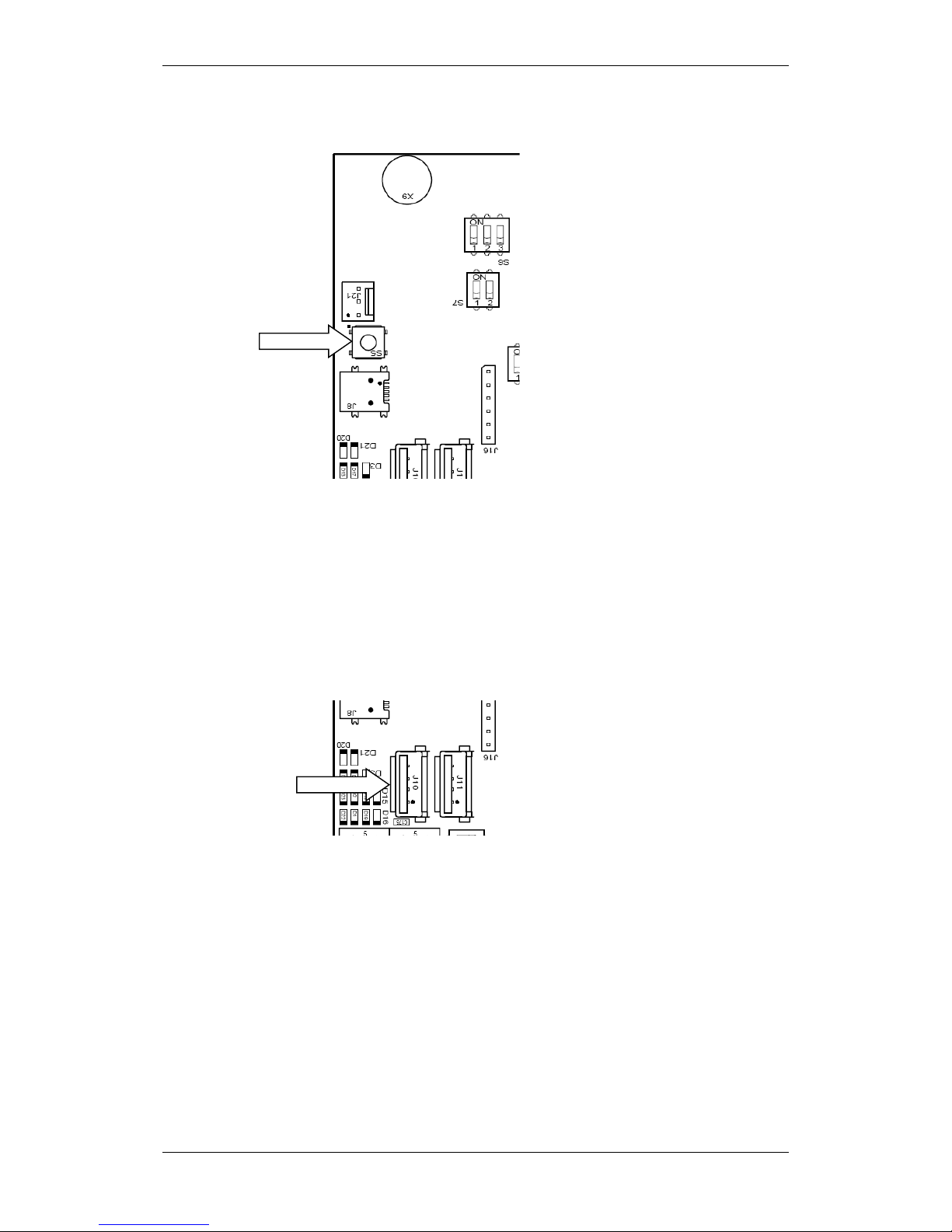
Appendix A - Controller Board BSA_400
Installation Handbook, AutroSafe Interactive Fire Detection System, Release 4, 116-P-ASAFE-INSTALL/DGB Rev. I, 2014-04-01,
Autronica Fire and Security AS
Page 65
14.6 Two-stage Push Button Reset (S5)
To shut down the system in a controlled manner, push less than 1
second.
To perform a hard reset without needing to do a controlled
shutdown (the system is already in system fault condition), push
and hold down the reset button S5 (approximately 10 seconds)
until the red LED indicators D20 and D21 are lit for a short moment
and you hear a click from the relay.
14.7 USB Ports (J10, J11)
There are 2 standard USB full speed (480Mbit) host ports; type A
connector. The ports are to be used for connection of an optional
printer or a memory stick .
Each USB host port is limited to a maximum of 100mA load.
S5
J10
J11
BSA-400
BSA-400

Appendix A - Controller Board BSA_400
Installation Handbook, AutroSafe Interactive Fire Detection System, Release 4, 116-P-ASAFE-INSTALL/DGB Rev. I, 2014-04-01,
Autronica Fire and Security AS
Page 66
14.8 Multifunction Serial Port Connector J3 -
AutroFieldBus and Fault Relay
A ribbon cable is connected between the Multifunction Serial Port
Connector J3 and the main terminal block L1(mounted on the DIN rail
inside the cabinet).
Connector J3 on
Controller Board BSA-400
Description
Connections to
terminal block
(L1)
J3.1
GND
L1.1
J3.2
GND
L1.2
J3.3
AutroFieldBus B
L1.3
J3.4
Multifunction Serial Port RS-422/RS485 A+
L1.4
J3.5
AutroFieldBus B’
L1.5
J3.6
Multifunction Serial Port RS-422/RS485 B-
L1.6
J3.7
AutroFieldBus B Reference
L1.7
J3.8
Multifunction Serial Port RS-422 X+
L1.8
J3.9
AutroFieldBus A
L1.9
J3.10
Multifunction Serial Port RS-422 Z-
L1.10
J3.11
AutroFieldBus A’
L1.11
J3.12
Multifunction Serial Port RS-232 TX
L1.12
J3.13
AutroFieldBus A Reference
L1.13
J3. 14
Multifunction Serial Port RS-232 RX
L1.14
J3.15
GND
L1.15
J3.16
Multifunction Serial Port Ref er enc e
L1.16
J3.17
Fault Relay Normal Open
L1.17
J3.18
GND
L1.18
J3.19
Fault Relay Normal Closed
L1.19
J3.20
Fault Relay Common
L1.20
The built-in AutroFieldBus Master driver serves as a communication
protocol between the AutroSafe panel, the BSD-340 PowerLoop
drivers and BSD-321 protocol converters, plus Power Board BSF-400.
It provides a redundant field bus system with a ring loop topology.
The AutroSafe panels have one Autr oFie ld Bus con nected, and each
AutroFieldBus can host up to 31 bus units.
The AutroFieldBus has short-circuit detection/isolation technology
which ensures that only one AutroFieldBus bus unit will be lost in case
of internal failure (short-circuit).
J3
BSA-400

Appendix A - Controller Board BSA_400
Installation Handbook, AutroSafe Interactive Fire Detection System, Release 4, 116-P-ASAFE-INSTALL/DGB Rev. I, 2014-04-01,
Autronica Fire and Security AS
Page 67
The ring loop topology ensures that no detectors/field units will be lost
due to a single break or short circuit of the AutroFieldBus cable.
The AutroFieldBus cable is normally 2-wire twisted pair category 5
copper cables, however, fibre optic cable is possible by use of
separate signal converters. The AutroFieldBus uses the same
guidelines as AUTROLON (AutroSafe version 3.8 and earlier), in
terms of cable lengths, fibre modem and boosters.
14.9 AutroFieldBu s Con nections
14.9.1 Ribbon Cable Connector BSA-400 to Terminal Block L1
Shielded cable required.
Terminal on BSA-400
Function
Terminal Block List L1
J3.9
AutroFieldBus A
L1.9
J3.11
AutroFieldBus A’
L1.11
J3.13
AutroFieldBus CT A
L1.13
J3.3
AutroFieldBus B
L1.3
J3.5
AutroFieldBus B’
L1.5
J3.7
AutroFieldBus CT B
L1,7
BSA-400
Ribbon cable connector
Terminal block L1

Appendix A - Controller Board BSA_400
Installation Handbook, AutroSafe Interactive Fire Detection System, Release 4, 116-P-ASAFE-INSTALL/DGB Rev. I, 2014-04-01,
Autronica Fire and Security AS
Page 68
14.10 Multifunction Serial Port Dipswitch Settings –
Switch S6 (RS-232, RS-422, RS-485)
Switch
RS-232
RS-422
RS-485
S6.1
Not applicable
OFF
ON
S6.2
Not applicable
OFF
ON
S6.3
Not applicable
OFF: Full duplex, two-way
simultaneous
communication.
ON: Half duplex
ON
14.11 Multifunction Serial Port Dipswitch Settings –
Switch S7
Switch
RS-232
RS-422
RS-485
S7.1
Not applicable
ON
ON
S7.2
Not applicable
ON
RS-422 requires two pair
of cables; one for RX and
one for TX.
One switch is used for the
termination of the RX line,
the other switch is used for
the termination of the TX
line. Both switches must
be ON.
OFF
RS-485 requires only one
pair of cables where TX/RX
are common. Switch S7.1 is
used for the termination.
S7.2 must be OFF.
S6
ON
ON
1 2 3
1 2
S7
BSA-400
BSA-400

Appendix A - Controller Board BSA_400
Installation Handbook, AutroSafe Interactive Fire Detection System, Release 4, 116-P-ASAFE-INSTALL/DGB Rev. I, 2014-04-01,
Autronica Fire and Security AS
Page 69
14.12 RS-485 Connections
14.12.1 Ribbon Cable Connector BSA-400 to Terminal Block L1
14.12.2 Switch Setting – Switch S6 and S7
Switch
RS-485
S6.1
ON
S6.2
ON
S6.3
ON
S7.1
ON
S7.2
OFF
14.13 RS-422 Connections
14.13.1 Ribbon Cable Connector BSA-400 to Terminal Block L1
14.13.2 Switch Setting – Switch S6 and S7
Switch
RS-422
S6.1
OFF
S6.2
OFF
S6.3
OFF
S7.1
ON
S7.2
ON

Appendix A - Controller Board BSA_400
Installation Handbook, AutroSafe Interactive Fire Detection System, Release 4, 116-P-ASAFE-INSTALL/DGB Rev. I, 2014-04-01,
Autronica Fire and Security AS
Page 70
14.13.3 Schematic of port equivalent:
TX_422_X+
Isolation
TX_422_Z-
RX_422_A+
RX_422_B-
Signal Reference
+5v_SER_0
8
14.14 RS-232 Connections
14.14.1 Ribbon Cable Connector BSA-400 to Terminal Block L1
14.14.2 Switch Setting – Switch S6 and S7
Switch
RS-232
S6.1
Not applicable
S6.2
Not applicable
S6.3
Not applicable
S7.1
Not applicable
S7.2
Not applicable

Appendix A - Controller Board BSA_400
Installation Handbook, AutroSafe Interactive Fire Detection System, Release 4, 116-P-ASAFE-INSTALL/DGB Rev. I, 2014-04-01,
Autronica Fire and Security AS
Page 71
14.15 Serial Debug Connector J21
A standard AutroSafe programming cable XJA-029 is to be connected
to this connector. The interface uses RS-232 115,2kbaud 8N1.
Connector
Description
Communication Parameters
J21.1
0V reference
115,2kbaud 8 data bit, none
parity, 1 stop bit
J21.2
RX
J21.3
TX
14.16 AL_Com+ Connector J5
Cable part number: XGE-1/10-50
Connector
Description
J5.1
AL_Com+ CTS
J5.2
0VIN
J5.3
AL_Com+ RXD
J5.4
0VIN
J5.5
Not Connected
J5.6
0VIN
J5.7
AL_Com+ TXD
J5.8
0VIN
J5.9
AL_Com+ RTS
J5.10
0VIN
J5
J21
Connected to Communication
Module BSL-310.
BSA-400
BSA-400
AL_Com+ debug

Appendix A - Controller Board BSA_400
Installation Handbook, AutroSafe Interactive Fire Detection System, Release 4, 116-P-ASAFE-INSTALL/DGB Rev. I, 2014-04-01,
Autronica Fire and Security AS
Page 72
14.17 LCD Backlight Connector J17
Connector
Description
J17.1
Backlight LED + 5V DC
J17.2
Backlight LED -
J17.3
Backlight LED -
J17.4
Backlight LED – 0V
14.18 Ethernet Ports (RJ-45 Connectors)
The BSA-400 board provides two separate 10/100Mbit Ethernet ports.
Each connector has 2 built-in status LEDs; Link and Act/Speed. The
connector is an RJ-45 modular jack, suitable for shielded cable CAT5
which allows cable lengths up to 100m.
Connector
Connector
Description
J1.1
J2.1
TX+, Transmit Data+
J1.2
J2.2
TX-, Transmit Data-
J1.3
J2.3
RX+, Transmit Data+
J1.4
J2.4
N.C.
J1.5
J2.5
N.C.
J1.6
J2.6
RX-, Transmit Data-
J1.7
J2.7
N.C.
J1.8
J2.8
N.C.
LED 1
Activity LED
LED 2
If ON, 100MBit/s, if OFF, 10MBit/s
1
8
1 2
J17
J2
J1 4 1
BSA-400
BSA-400

Appendix A - Controller Board BSA_400
Installation Handbook, AutroSafe Interactive Fire Detection System, Release 4, 116-P-ASAFE-INSTALL/DGB Rev. I, 2014-04-01,
Autronica Fire and Security AS
Page 73
14.18.1 Ethernet Straight Through Cable
Name
Pin
Cable Color
Pin
Name
TX+
1
White/Orange
1
TX+
TX- 2 Orange
2
TX-
RX+
3
White/Green
3
RX+
4 Blue
4 5 White/Blue
5 RX- 6 Green
6
RX- 7
White/Brown
7 8 Brown
8
14.19 Fault messages Power Board BSF-400
Fault category: Power
Fault message
Cause
Remedy
BSF-400 – Power supply fault
General Fault LED blinking
Power supply OK, but
power supply cable(s)
unplugged
Re-insert power supply
cables
Power suppl y
malfunction
Replace Mean Well or
Power Box PSU unit.
BSF-400 – Mains fault
Mains Fault LED blinking
General Fault LED blinking
Mains is disconnected,
loss of power from mains
source
Re-insert mains plug,
check mains power
source
Mean Well PSU control
cable is
disconnected/broken
Re-insert or replace
control cable.
BSF-400 – Battery not connected
Battery Fault LED blinking
General Fault LED blinking
Battery is disconnected
Re-connect battery
Battery is short circuited
Remove short circuit
BSF-400 – Battery fuse blown
Fuse Fault LED blinking
General Fault LED blinking
Battery fuse is blown
Replace with appropriate
fuse
BSF-400 – Battery temperature sensor
open circuit
Battery Fault LED blinking
General Fault LED blinking
Battery temperature
sensor cable is
disconnected or broken
Replace battery
temperature sensor cable
BSF-400 – Battery temperature sensor
short circuit
Battery Fault LED blinking
General Fault LED blinking
Battery temperature
sensor cable is short
circuited
Remove short circuit
BSF-400 Output [A1/A2/B1/B2/C1/C2]
electronic fuse blown
Fuse Fault LED blinking
General Fault LED blinking
A short circuit or very
high current draw has
occurred on power
output.
Warning: BSF-400 will try
to re-power automatically.
Remove corresponding
fuse before working with
faulty external equipment.
Remove short circuit and
press reset on AutroSafe
panel to reset electronic
fuse.
1
8
1
8

Appendix A - Controller Board BSA_400
Installation Handbook, AutroSafe Interactive Fire Detection System, Release 4, 116-P-ASAFE-INSTALL/DGB Rev. I, 2014-04-01,
Autronica Fire and Security AS
Page 74
Fault category: Power
Fault message
Cause
Remedy
BSF-400 Output [A1/A2/B1/B2/C1/C2]
fuse blown
Fuse Fault LED blinking
General Fault LED blinking
The fuse is blown.
Replace with appropriate
fuse
BSF-400 Output [A1/A2/B1/B2/C1/C2]
voltage to low.
General Fault LED blinking
This may occur when
running on battery only
and battery voltage is
below 18V.
Insert mains to charge
batteries.
This warning may occur
when a fuse is removed
from an output with no
load.
Accept fault in AutroSafe.
BSF-400 Battery Relay Fault
This warning may occur
during start-up if a
battery is not connected
Connect battery, or put
dip switch 5 to OFF
position if no battery is to
be used
The relay fault warning
may occure if there is a
hardware fault.
Replace BSF-400 board.
BSF-400 Battery voltage to low
This message may occur
under start-up when
battery voltage is to low,
i.e. charging current is
>1100mA.
Message will clear when
charge current drops
below 400mA.

Appendix B - Power Supply
Installation Handbook, AutroSafe Interactive Fire Detection System, Release 4, 116-P-ASAFE-INSTALL/DGB Rev. I, 2014-04-01,
Autronica Fire and Security AS
Page 75
15. Appendix B - Power Supply
15.1 Power Cabinet and Power Units
AutroSafe 4 provides the following power cabinet and power units:
Power Cabinet BP-405
Power Unit BPS-405
Power Unit BPS-410
15.1.1 Power Cabinet BP-405
The Power Cabinet BP-405 contains the following:
24V/5A power supply (BPS-405, Meanwell Power Sup ply)
Power Board BSF-40 0, inc ludi ng:
AutroFieldBus interface
115VAC /230VAC input
6 outputs 24VDC (max. 2A each)
1 fault relay output
2x12V, 18Ah batteries
For detailed information, refer to this chapter (Power Supply) and
datasheet.
15.1.2 Power Unit BPS-405
The Power Unit BPS-405 contains the following:
24V/5A power supply
Power Board BSF-40 0, inc ludi ng:
AutroFieldBus interface
115VAC /230VAC input
6 outputs 24VDC (max. 2A each)
1 fault relay output
For detailed information, refer to this chapter (Power Supply) and
datasheet.
15.1.3 Power Unit BPS-410
Note:
The BPS-410 Power Unit 24VDC/10A is delivered as two separate
part numbers:
116-BPS-410 for 230VAC
116-BPS-410/115 for 115VAC
The Power Unit BPS-410 contains the following:
24V/10A power supply
Power Board BSF-40 0, inc ludi ng:
AutroFieldBus interface
115VAC or 230VAC input
6 outputs 24VDC (max. 2A each)
1 fault relay output
For detailed information, refer to this chapter (Power Supply) and
datasheet.

Appendix B - Power Supply
Installation Handbook, AutroSafe Interactive Fire Detection System, Release 4, 116-P-ASAFE-INSTALL/DGB Rev. I, 2014-04-01,
Autronica Fire and Security AS
Page 76
15.2 Circuit Board Layout BSF-400
1
2
3
AFB A
AFB A"
AFB CT A
4
5
6
AFB Earth Fault Sense
AFB B
AFB B"
78AFB CT B
AFB Earth Fault Sense
J2
J26
1 6
1
2
3
Alarm NO
Alarm Com
RC (Remote test)
4
5
6
Fault Relay NO
Fault Relay NC
Fault Relay Com
F1 A1 F2AL
F2 A2 F2AL
J19
S1 Reset
High Low
8
7
6
Internal Fault
General Fault
Battery Fault
5
43Fuse Fault
21Mains Fault
Power ON
J24
J23
J22
0V
C2
J21
F2AL
F3 B1
F2AL
F4 B2
F2AL
F5 C1
F2AL
F6 C2
AFB Adress (H & L)
1
2
3
Earth Fault Sense ON/OFF
Battery relay (see manual)
AFB present
4
5
6
Battery present
61
S6
ON
OFF
source (see manual)
S2, Start on standby
15
5
4
3
2
1
Therm.+
Therm.PSF
-V
Vcon
+
-
BATT
J20
J17
F7 Battery
F8 Charger
1 2 3
Charger +24V
Charger 0V
Earth
J25
E-2868
J18
+
0V
+
C1
0V
+
B2
0V
+
B1
0V
+
A2
0V
+
A1
X11 X10
AFB Com
BP-410/01
BP-405/01
T10T5T10
T5
F7 F8
AH AH
AH AH
S5
AFB Earth Fault Off
AFB Earth Fault On
1
OFF
ON
2
OFF
ON

Appendix B - Power Supply
Installation Handbook, AutroSafe Interactive Fire Detection System, Release 4, 116-P-ASAFE-INSTALL/DGB Rev. I, 2014-04-01,
Autronica Fire and Security AS
Page 77
15.3 Description
BSF-400 is a power monitor and controller board providing a
communication interface, AutroFieldBus. The board has also the
ability to operate stand alone with no communication. The fault relay is
energized as standard with its own watchdog.
The power board provides power to AutroSafe, AutroSafe’s existing
I/O module stacks, battery monitoring and charging, plus 24 voltage
contacts for other external equipment.
2 x 24V outputs of 2A to AutroSafe panel
2 x 24V outputs of 2A to I/O stack
2 x 24V outputs of 2A to third-party equipment
1 input for battery
1 input for battery charger
Communication
Power control for battery
Control signals for battery charger
All internal voltage levels are monitored
Temperature sensor for compensation of charger voltage
BSF-400 has short circuit protection on all outputs such that a short
circuit will not affect other outputs. Batteries that are connected will be
charged with temperature compensation to ensure long battery life
regardless of temperature (within the specified operating temperature
range).
All outputs on terminations A, B and C are specified to a maximum
current of 2A. There are no minimum power ratings for the outputs.
The maximum power that may be used from each output is 2A and
there is a current limiter implemented at 7A.
15.4 Power Block Diagram – Example
BSL-310
BSS-310A
BSF-
400
A1
A2
B1
B2
C1
C2
BSA-400
External
equipment:
max 2A
External
equipment:
max 2A
BSA-400 BSA-400
A power consumption
account must be done
to ensure that max
delivery of power is
not exceeded.
BSS-311

Appendix B - Power Supply
Installation Handbook, AutroSafe Interactive Fire Detection System, Release 4, 116-P-ASAFE-INSTALL/DGB Rev. I, 2014-04-01,
Autronica Fire and Security AS
Page 78
15.5 Batteries
The recommended cable parameter for BSF-400 is minimum 1,5mm2 /
15,4 AWG.
There is no minimum requirement for drawing power.
15.5.1 Power Unit BPS-405
The inputs for the battery and the charger are specified to handle up
to 10A. The fuses, F7 battery and F8 Charger, shall have 5A fuses.
Batteries that are to be used with BSF-400 are Fiamm batteries with
the maximum size of 18Ah. The minimum size of batteries if batteries
are connected is 7,2Ah.
The maximum current that may be drawn from the batteries when the
primary power source is disconnected is 5A for BPS-405.
There is no minimum requirement for drawing power. The maximum
power that may be drawn from BPS-405 is 3A.
I max A
Maximum battery current output when
mains disconnected
Fuse F7:
Charger,
Battery
3A
5A
T5AH
The maximum internal resistance for a battery connected to a
BSF-400 is 0,8Ω, any higher resistance than this will be detected as a
fault in the battery by BSF-400.
NOTE:
If power to the system is supplied exclusively from the batteries (in
case of a power supply failure), and the voltage is below 19V, the
Power Board BSF-400 will perform a controlled shutdown (i.e. the
power is switched OFF).

Appendix B - Power Supply
Installation Handbook, AutroSafe Interactive Fire Detection System, Release 4, 116-P-ASAFE-INSTALL/DGB Rev. I, 2014-04-01,
Autronica Fire and Security AS
Page 79
15.5.2 Power Unit BPS-410
The inputs for the battery and the charger are specified to handle up
to 10A. The fuses, F7 battery and F8 Charger, shall have 10A fuses.
Batteries that are to be used with BSF-400 are Fiamm batteries with
the maximum size of 18Ah. The minimum size of batteries is 12Ah.
The maximum current that may be drawn from the batteries when the
primary power source is disconnected is 10A for BPS-410.
The maximum power that may be drawn from BPS-410 is 8A.
I max A
Maximum battery current output when
mains disconnected
Fuse F7:
Charger,
Battery
8A
10A
T10AH
The maximum internal resistance for a battery connected to a
BSF-400 is 0,6Ω, any higher resistance than this will be detected as a
fault in the battery by BSF-400.
NOTE:
If power to the system is supplied exclusively from the batteries
(in case of a power supply failure), and the voltage is below 19V,
the Power Board BSF-400 will perform a controlled shutdown (i.e.
the power is switched OFF).
15.6 Battery Charging
The charging voltage is temperature controlled, so optimal charge for
each temperature is maintained.
Charge current for the BPS-405 is also controlled, so that the charging
voltage will decrease when the charge current reaches 2A.
A “Battery voltage too low”-warning will displa y on AutroSaf e s ystem s
connected to the BPS-405 or BPS-410 via AutroFieldBus. The
message will clear when charge current drops below 400mA.
Attention: The battery temperature sensor must be placed on the
batteries. If the sensor is placed in warmer or colder places, the
charging voltage will be wrong, and lower battery capacity and/or
shorter battery life may be expected.
The charging voltage at 25
o
C is 27, 2 V DC.
Note that when the BSF-400 board is turned OFF and batteries are
connected to the battery termination, the leak current of the batteries
is 6mA.

Appendix B - Power Supply
Installation Handbook, AutroSafe Interactive Fire Detection System, Release 4, 116-P-ASAFE-INSTALL/DGB Rev. I, 2014-04-01,
Autronica Fire and Security AS
Page 80
15.7 Button S2 – Start on S2 on Standby Source
By pressing button S2 one second, the system can be started (without
mains source) from the battery when the battery voltage is >20V DC.
Note that, if the battery voltage is less than 20V DC, the button will
have no affect (hardware controlled).
Troubleshooting:
In some cases the voltage can be slightly above 20V DC and drop
rapidly to below 20V DC. The relay will then tend to chatter. In this
case, it is recommended that the system is not started until the battery
is fully charged.
0V
C2
J21
F2AL
5
6
Battery present
61
S6
ON
OFF
source (see manual)
S2, Start on standby
15
5
4
3
2
1
Therm.+
Therm.PSF
-V
Vcon
+
-
BATT
J20
J17
F7 Battery
F8 Charger
1 2 3
Charger +24V
Charger 0V
Earth
J25
E-2868
+
V
BP-410/01
BP-405/01
T10T5T10
T5
F7 F8
AH AH
AH AH
S2:
Start on
standby source
S2
BSF-400

Appendix B - Power Supply
Installation Handbook, AutroSafe Interactive Fire Detection System, Release 4, 116-P-ASAFE-INSTALL/DGB Rev. I, 2014-04-01,
Autronica Fire and Security AS
Page 81
15.8 Configuration Settings
The BSF-400 board may be used in several different configurations.
The board is configured by means of two switches:
Dipswitch S5 and S6 (refer to dipswitch tables, 0)
Rotary switches X10 and X11 - AutroFieldBus address switch.
Each Power Board is given a unique address.
If for any reason the settings on dipswitch S6, X10 or X11 have been
changed, the BSF-400 must be restarted by pressing the reset button
S1 for this change in order to be taken into account.
The power has two modes of user interaction; standalone (S6.3 OFF)
or with communication to the AutroSafe system.
1
2
3
AFB A
AFB A"
AFB CT A
4
5
6
AFB Earth Fault Sense
AFB B
AFB B"
78AFB CT B
AFB Earth Fault Sense
J2
1 6
1
2
3
A
A
R
4
5
6
F
F
F
F1
F2
J19
S1 Reset
High Low
8
7
6
5
4
3
2
1
J24
J23
J22
0V
C2
J21
F2AL
F3 B1
F2AL
F4 B2
F2AL
F5 C1
F2AL
F6 C2
A
1
2
3
Earth Fa
Battery
AFB pre
4
5
6
Battery
61
S6
ON
OFF
15
5
4
3
2
1
Therm.+
Therm.PSF
-V
Vcon
+
-
BATT
J20
J17
F7 Battery
F8 Charger
1
Charger +24V
J18
+
0V
+
C1
0V
+
B2
0V
+
B1
0V
+
A2
0V
+
A1
X11 X10
BP-410/01
BP-405/01
T10T5T10
T5
F7 F8
AH AH
AH AH
S5
AFB Earth Fault Off
AFB Earth Fault On
1
OFF
ON
2
OFF
ON
Dipswitch S6
AutroFieldBus
Address Switch
X10, X11
Dipswitch S5
S1 Reset button
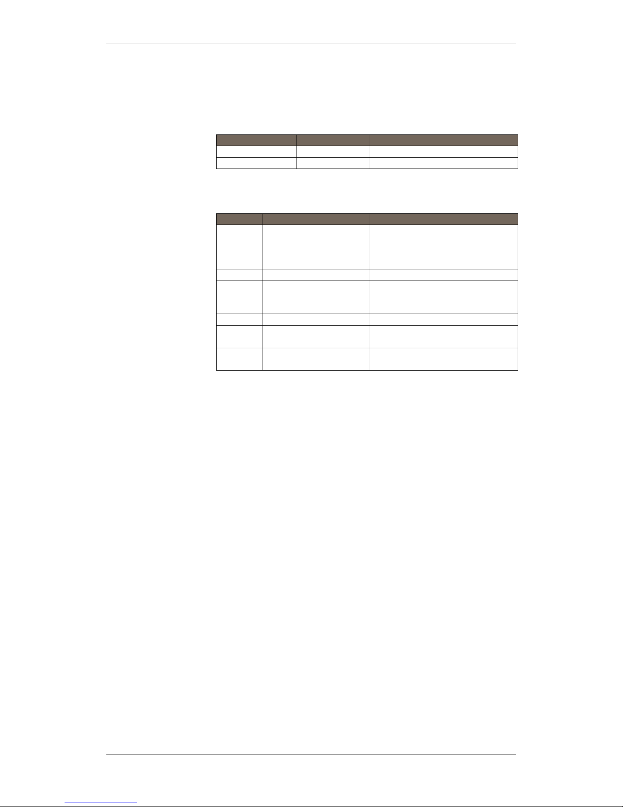
Appendix B - Power Supply
Installation Handbook, AutroSafe Interactive Fire Detection System, Release 4, 116-P-ASAFE-INSTALL/DGB Rev. I, 2014-04-01,
Autronica Fire and Security AS
Page 82
15.9 Dipswitch table – S5 and S6
Dipswitch table – S5
S5.1
S5.2
Function
OFF
OFF
AutroFieldBus earth fault OFF
ON
ON
AutroFieldBus earth fault ON
Dipswitch table – S6
Switch
Name
Comment
S6.1
Earth Fault
ON: Earth fault monitoring
activated
OFF: Earth fault monitoring
deactivated
S6.2
--
NA
S6.3
AutroFieldBus
ON: AutroFieldBus connected
OFF: AutroFieldBus not
connected
S6.4
Not used
NA
S6.5
Battery
ON: Battery connected
OFF: Battery not connected
S6.6
Power Unit Type
ON: BPS-405
OFF: BPS-410

Appendix B - Power Supply
Installation Handbook, AutroSafe Interactive Fire Detection System, Release 4, 116-P-ASAFE-INSTALL/DGB Rev. I, 2014-04-01,
Autronica Fire and Security AS
Page 83
15.10 Connectors
Connector
Description
BPS-405 / BPS-410
J25
Power Supply
To BSP-405 (Mean Well Power Supply)
J20
Battery
connector
To Battery 27,3VDC charging
J17
Temp.
sensor/Mean
Well Control
Applies to BPS-405 only.
Temperature sensor (close to battery) and Mean
Well PSU
(1-3) from power, (4-5) temp. sensor
J26 1-3
Powernet
control
Applies to BPS-410 only.
Control wires for power supply.
J26 4-6
Fault Relay
Applies to both BPS-405 and BPS-410.
Fault Relay (NO, NC, com) Fault output.
J19
Output A1
24V/2A (BSA-400 Vin1 +/0V)
J18
Output A2
24V/2A (BSA-400 Vin2 +/0V)
J24
Output B1
24V/2A, general power output
J23
Output B2
24V/2A, general power output
J22
Output C1
24V/2A with interrupt at init
J21
Output C2
24V/2A with interrupt at init
The power outputs have different properties. They can all deliver 2A
each (limited by total power available).
Output
Description
Output A
These will always be ON. Will be turned OFF by a
short- circuit only.
Output B
These are initially ON, but may be switched OFF/ON
from AutroSafe.
Output C
These will be turned OFF during start-up of BSF-400
(initialization). May be switched OFF/ON from
AutroSafe. Power to I/O modules.

Appendix B - Power Supply
Installation Handbook, AutroSafe Interactive Fire Detection System, Release 4, 116-P-ASAFE-INSTALL/DGB Rev. I, 2014-04-01,
Autronica Fire and Security AS
Page 84
15.11 Fault Relay Watchdog J26
The fault relay on the BSF-400 board has its own watchdog. If the
CPU stops for any reason the watchdog will turn over the fault relay if
it is not fed within 1 secon d .
If for any reason the BSF-400 restarts, it takes 5 seconds before the
fault relay is in the correct position:
J26.4 (normally open contact): closed contact when the unit is not
supplied with power or there is a fault on the unit
J26.5 (normally closed contact): closed when no faults exist
J26.6 (common): common for fault relay
Watch
dog
CPU
COM
NC
NO
Note that the fault relay will not be turned over for communication
faults on the AutroFieldBus.
The green and red LED beneath the cover are indicators for AFB-RX
and – TX. Hearbeat is indicated when these LEDs are blinking
simultaneously. Rapid blinking indicates heavy traffic on the
AutroFieldBus. If the red LED is weak and the green one is not lit,
there is no communication between the BSF-400 board and the
AutroFieldBus.
LED number / Colour
/ Schematic reference
Mechanic name (E-
2868)
Description
1. Green
Power ON
This LED signifies that the BSF-400 has power and
will be OFF for 20 ms every second.
2. Yellow
Mains Fault
Will blink if power supply lacks 230V AC connection.
3. Yellow
Battery Fault
Blinking LED; for all battery faults, except when a
battery fuse is blown
4. Yellow
Fuse Fault
Blinking LED for all fuse faults and also for all
electronic fuse faults.
5. Yellow
AutroFieldBus Com
The LED is lit shortly if AutroFieldBus
communication is received or transmitted.
6. Yellow
For future use.
7. Red
General Fault
Blinking LED if there are one or more faults in the
power supply system.
8. Yellow
Internal Fault
Blinking LED if there exist one or more internal faults
on the BSF-400. This includes temperature on the
BSF-400 out of bounds.
Internal faults are mostly PCB errors. This LED
blinks in a much faster cycle than the others.
All blinking LEDs, except where otherwise stated, will blink with 0,5
seconds ON and 0,5 seconds OFF.
J26.4
J26.5
J26.6
Fault relay

Appendix B - Power Supply
Installation Handbook, AutroSafe Interactive Fire Detection System, Release 4, 116-P-ASAFE-INSTALL/DGB Rev. I, 2014-04-01,
Autronica Fire and Security AS
Page 85
15.12 Battery Resistance Measurement
Every fourth hour, battery impedance measuring is conducted.
This is conducted by lowering the PSU voltage so that all loads are
powered from the batteries for a period of 60 seconds, then a built in
resistor is turned ON for 2 seconds. BPS-405/BPS-410 will then
measure the voltage increase between the resistor ON and OFF and
thus calculate the battery resistance. This measurement includes the
wires to and from the battery.
The battery high resistance fault is given when the total resistance of
the battery and battery cables is:
Type
Resistance
Power Unit BPS-405
0.8Ω
Power Unit BPS-410
0.6Ω
If such a fault is given, check the cable resistance or replace the
batteries.
15.13 Electronic fuses
15.13.1 Power outputs
Power outputs A1, A2, B1, B2, C1 and C2 are protected by both
electronic and regular fuses. The electronic fuses will trip if a current
between 3.5A and 7A is drawn. The electronic fuse will turn OFF
power within approx. 10ms of a short circuit. The BSF-400 will try to
turn ON power 3 times with ~50s interval between each try.
If an external fault is not resolved, BSF-400 will not try to re-power
more than 3 times. A reset on an AutroSafe panel or pushing reset
button S1 will force the BSF-400 to retry.
IMPORTANT:
To be safe, remove regular fuse before troubleshooting external faulty
equipment.

Appendix B - Power Supply
Installation Handbook, AutroSafe Interactive Fire Detection System, Release 4, 116-P-ASAFE-INSTALL/DGB Rev. I, 2014-04-01,
Autronica Fire and Security AS
Page 86
15.13.2 Battery Input
The battery input is protected by an electronic short-circuit detector
and a regular fuse. If a short circuit is detected, the battery relay will
turn OFF within approx 50ms. The AutroSafe AutroFieldBus system
will then report “Battery not connected”.
15.14 Part of an AutroFieldBus Network
As a part of an AutroFieldBus network, the power module is
configured before start-up using dipswitches, some data, for example,
“Low voltage”-warning is given from an AutroSafe configuration via
AutroFieldBus.
Diagnostic outputs are given onboard with LEDs and alarm relay, and
on AutroSafe panels with audible alarms and display messages.
The LEDs and fault relay will not indicate any failure before the
AutroSafe has AutroFieldBus connection and the AutroSafe system
has been initialized.
15.15 Power Unit BPS-405 / BPS-410 as Standalone
In the standalone system, user input is given during installation only,
using dipswitches onboard. Set dips witc h S6. 3 OFF to set the power
supply in standalone mode.
Diagnostic outputs are given onboard with LEDs and fault relay.

Appendix B - Power Supply
Installation Handbook, AutroSafe Interactive Fire Detection System, Release 4, 116-P-ASAFE-INSTALL/DGB Rev. I, 2014-04-01,
Autronica Fire and Security AS
Page 87

Autronica is a leading innovator, manufacturer and supplier of fire safety equipment. Our
products ensure safety in applications on land and sea worldwide. The company is owned by
United Technologies Corporation (UTC) and employs more than 380 people with great skill and
experience in the developing, manufacturing and marketing of fire safety equipment.
Autronica Fire and Security AS is an international company based in Trondheim, a dynamic city
known as the technological hotspot of Norway.
Protecting life, environment and property
Autronica Fire and Security AS
Haakon VIIS gt. 4, NO-7041 Trondheim, Norway | Tel: +47 90 90 55 00 | Fax: +47 73 58 25 01
E-mail: info@autronicafire.no | www.autronicafire.com
 Loading...