

Autotrol Performa 440i Control, Performa 960F Control, Performa 940F Control Installation, Operation And Maintenance Manual
Page 1

®
TM
Autotrol Performa Filter Valve Series
440i Control
940F Control
960F Control
Water Conditioning Control System
Installation, Operation and Maintenance Manual
Page 2

Table of Contents
Installation . . . . . . . . . . . . . . . . . . . . . . . . . . . . 3
Location S election
Water Line Connection
Drain Line Connection
Placing Conditioner into Operation. . . . . . . . . 4
Electrical C o nnection
400 Series Control Settings. . . . . . . . . . . . . . . 5
440i
Programming
900 ProSeries Control Settings . . . . . . . . . . . . 5
940F
Programming
Manual Regeneration
960F
Programming
Level I Parameters
Level II Parameters
Regeneration . . . . . . . . . . . . . . . . . . . . . . . . . 11
Manual Regeneration
Automati c Re ge ner a tio n
Removin g the Valve As s em bly or Servicing . 12
Removing 440i Contro l for Servicing. . . . . . . 12
Removin g the 940F and 96 0F Controls for
Servicing . . . . . . . . . . . . . . . . . . . . . . . . . . . . 13
Preventative Maintenance. . . . . . . . . . . . . . . 14
Water Meter Maintenance
Specifications . . . . . . . . . . . . . . . . . . . . . . . . 15
Control Valving Identification. . . . . . . . . . . . . 17
Valve Disc Principle of Operation . . . . . . . . . 17
Flow Diagrams. . . . . . . . . . . . . . . . . . . . . . . . 17
Replacement Parts . . . . . . . . . . . . . . . . . . . . 19
Troubleshooting. . . . . . . . . . . . . . . . . . . . . . . 22
2
Page 3
Installation
All plumbin g and electrical connections mus t co nfo r m
to local codes.
Inspect unit carefully for carrier shortage or shipping
damage.
Location Selection
1. The distance between the unit and a drain should be
as short as possible.
2. If it is likely that supplementary water treatment
equipment will be required, make certain adequate
additional space is available.
3. Do not install any unit closer to a water heater than
a total run of 10 feet (3 m) of piping between the
outlet of the conditioner and the inlet to the heater.
Water heaters can some times overheat to the
extent they will tr ans mit heat back down the co l d
pipe into the unit control valve.
Hot water can severely damage the conditioner. A
10-foot (3-m) total pipe run, including bends,
elbows, etc. , is a reasona bl e di st an ce to hel p
prevent this possibil ity. A positive way to preven t
hot water flowing from heat source to the
conditioner, in the event of a negative pressure
situation, is to ins t all a check valve in the so ft
water piping from the conditioner . If a ch eck valve
is installed, make cer tain th e wate r heati ng unit
is equipped with a property rated temperature
and pressure safety relief valve. Also, be
certain that local codes are not violated.
4. Do not locate unit where it or its connections
(including the drain) will ever be subjected to room
temperatures under 34
o
(49
C).
5. Do not install unit near acid or acid fumes.
Water Line Connection
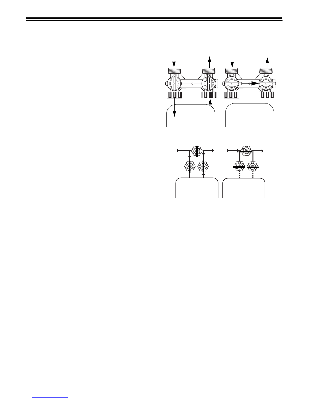
The installation of a bypass valve system is
recommended to provide for occasions when the water
conditioner must be bypassed for hard water or for
servicing.
The most common bypass systems are the Autotrol
Series 1265 bypass valve (Figure 1) and plumbed-in
globe valves (Figure 2) . Though both are similar in
function, the Autotrol Series 1265 bypass offers
simplicity an d eas e of o pe r atio n.
o
F (1oC) or over 120oF
Not in Bypass
In
B
Y
P
A
S
S
Conditioner
Water
Out
B
Y
P
A
S
S
In
A
P
S
Y
S
B
In Bypass
Water
Conditioner
Out
A
S
S
P
Y
B
Figure 1
Not in Bypass In Bypass
Water
Conditioner
Water
Conditioner
Figure 2
Drain Line Connection
Note: Standard commercial practices are expressed
here. Local codes may require changes to the following
suggestions.
1. Ideally located, the unit will be above and not mor e
than 20 feet (6.1 m) from the drain. For such
installations, using an appropriate ad apter fit ting ,
connect 1/2-inch (1.3-cm) plastic tubin g to the drain
line connection of the control valve.
2. If the bac kw as h flo w rate exceeds 5 gpm
(22.7 Lpm) or if the unit is located more than 20 feet
(6.1 m) from drain, use 3/4 -inch (1.9-cm) tubing for
runs up to 40 feet (12.2 m). Also, purchase
appropriate fitting to connect the 3/4-inch tubing to
the 3/4-inch NPT drain connection.
3. If the unit is located where the drain line must be
elevated , yo u may elevate the line up to 6 feet
(1.8 m) providin g th e ru n does not exceed 15 feet
(4.6 m) and water pressure at conditioner is not less
than 40 psi (2.76 bar). You may elevate an
additional 2 feet (61 cm) for each additional 10 psi
(0.69 bar).
4. Where the drain line is elevated but empties into a
drain bel ow the lev el of the control valve, fo rm a
3
Page 4
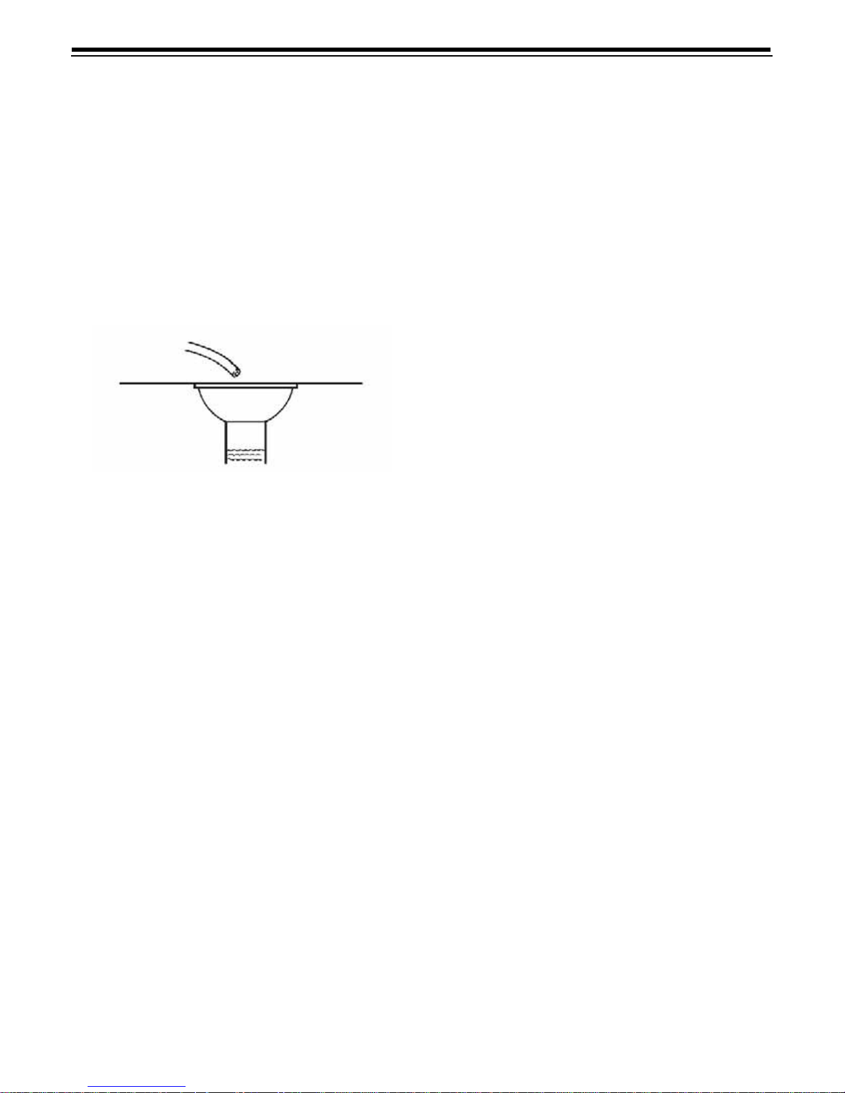
7-inch (18-cm) loop at the far end of the line so that
the bottom of the loop is level with the drain line
connection . T his will prov id e an adequate sipho n
trap.
5. Where the dr ain empties into an ov erh ea d s ew er
line, a sink-t ype trap must be used.
IMPORTANT: Never insert drain line into a drain, sewer
lin e o r tra p. Alway s allow an air g ap between the drain
line and the wastewater to prevent the possibility of
sewage bein g ba ck -s ip ho n ed into the co nditioner.
Right Wa y
Figure 3
Note: Standard commercia l prac tices have been
expressed here. Loc al co d es may require changes to
these suggestions.
c. When all of the air ha s been purged from the
tank (water begins to flow steadily from the
drain), open the main supply valv e all the way.
d. Allow water to run to drain until clear.
e. Turn off water supply and let the uni t stan d for
about five minutes. This will allow all trapped air
to escape from the tank.
4. Place the conditioner into operation.
a. Advance t he indicato r knob or cycle indicator
COUNTERCLOCKWISE to the SERVICE
position and run water from a nearby faucet
until the water is clear.
Electrical Conne ction
100 VAC, 115 VAC, and 230 VAC units: Remove twist
tie from the powe r co rd and ex tend co rd to its fu ll
length. Make sure the power source matches the rating
printed on the control. Be certain a wall switch does not
control the outlet.
12 VAC: Connect the plug of the transformer (supplied)
secondar y cab le to t he ma tin g soc ke t at th e rear or
bottom of the timer housing. Be certain the transformer
is secure and is plugged int o a power sour ce of corr ect
voltage that is n o t con trolle d b y a wall s wi tch .
Placing Conditioner into Operation
After all previous steps have been completed the unit is
ready to be placed into operation. Follow these steps
carefully.
1. Remove control valve cover.
Note: The following step s will require turning the
indicator knob (Figure 4 and Figure 5) or the cycle
indicator (Figu re 7) to various positions. Manuall y
rotate the camshaft COUNTERCLOCKWISE only
until indicator kn ob an d cy cle indi cato r p oi nts to
des i re d posi tion . ( See manua l re gene ratio n
sections for each control’s manual operatio n. )
2. Rotate indicator knob or cycle indicator
COUNTERCLOCKWISE until it points directly to
the word BACKWASH.
3. Fill med ia tan k with water.
a. With wate r supply off , place the by pass valve(s )
into the “service” position.
b. Op en wa ter su pp ly va lv e v er y slow ly to
approximately the 1/4 open position.
IMPORTANT: If opened t oo rapidly or too far, media
may be lost. In the 1/4 open positi on , you sh ould hear
air escaping slowly from the drain line.
4
Page 5
400 Series Control Settings
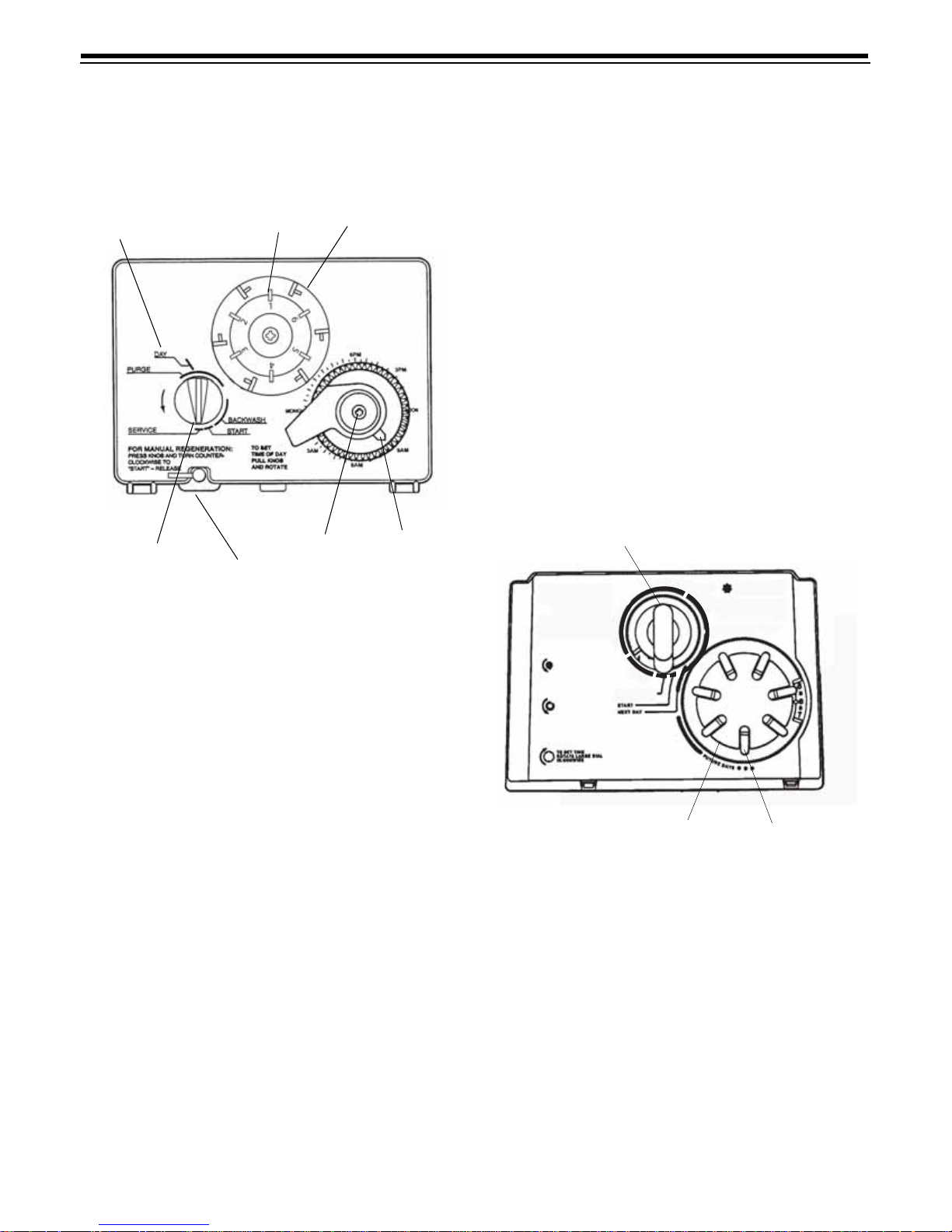
440i Control
Day Arro w
Skipper Pins
Skipper Wheels
extra regeneration can be achieved. Depress the
indicator knob on the 440i (Figure 4) with a wide-blade
screwdriver and turn COUNTERCLOCKWISE to
START to initiate a regener atio n. It will tak e a few
minutes for regeneration to start. A normal regeneration
will take approximately two hours.
Manual Regeneration
Electrici ty is used only to run the control an d to rotate
the camshaft. All other functions are operated by water
pressure. Therefore, in the event of a power outage, all
the regeneration p o si tion s may be dia led ma nually by
depressin g the indicator knob and turning
COUNTERCLOCKWISE (Figure 4). The foll o wing
cycle times should be used for proper regeneration :
BACKWASH - 20 minutes
FAST RINSE - 10 minutes
900 ProSeries Control Settings
940F Control
Indicator Knob
Timer Knob
Time Arrow
Timer Locking Pin
Figure 4
Programming
1. Set days of regeneration on skipper wheel (Figure 4).
• Pull all skipper pins outward (away from
control).
• Rotate skipper wheel until day arrow points to
current day or number 1.
• Depress skipper pin ( s) at da y(s) fo r which
regeneration i s desired.
2. Set the time of day.
• Grasp timer k n ob and pull outward.
• Rotate in either direction until the timer arrow
points to the actual time of day.
• Release timer knob.
Note: with the time of day properly set, the conditioner
will regenerate at about 2:30 a.m. If you prefer to have
the unit regenerate at an earlier or later time, simply set
current time-of-d ay ac co rding ly (e.g. , to h ave th e unit
regenerate at 4:30 a.m. - two hours later - set the clock
two hours earlier than the actual time of day.)
Note: The timer locking pin should always be horizontal
(Figure 4) during operation.
Guest Cycle
When abnormally high water usage exhausts your
water cond ition e r ’s capacity ahea d of s ch ed ule, an
Indicator Knob
TM
Performa Filter
FOR MANUAL
BACKWASH
ROTATE POINTER
COUNTER
CLOCKWISE TO
START POSITION
TO ADJUST BACKWASH
MINUTES, ROTATE
SMALL DIAL COUNTER
CLOCKWISE.
DO NOT ADJUST
DURING BACKWASH
N
I
R
T
S
A
F
S
E
R
V
I
C
E
BACKWASH COMPLETE
Clock Dial
E
S
B
A
C
K
W
A
S
H
TO SET
REGENERATION
DAYS PRESS PINS IN
Day Pins
Figure 5
Programming
1. Set da ys of regenera tion (Figure 5).
• Pull all day p ins outward (away from cont rol ).
• Depress day pin(s) for whi ch regener ation is
desired.
Note: The NEXT DAY day pin is n oted on the timer
face. Depressing this pin will insure a regeneration the
next day at approximately 2:00 a.m. Since the calendar
cap progre sses CLOCKWISE, depr essing the day pin
immediately COUNTERCLOCKWISE will insure a
regeneration the following day at 2:00 a.m. This
progression is noted on the timer face as “FUTURE
DAYS”.
5
Page 6
2. Set the time of day.
Time of Day
Time of Regen
Fact or A
Fact or B
Capacity
Regen Time
Remaining
R
E
G
E
N
E
R
A
T
IO
N
C
O
M
P
L
E
T
E
F
A
S
T
R
I
N
S
E
B
A
C
K
W
A
S
H
P
M
Performa
Filter
TM
• Rotate Clock Dial CLOCKWISE until the pointer
is directed at the curre nt time .
Note: With the time of day properly set, the conditioner
will regenerate at about 2:00 a.m. If you prefer to have
the unit regenerate at an earlier or later time, simply set
the current time-of-da y ac co rdingly (e. g., to have the
unit REGENERATE at 4:00 a.m. - two hours later - set
the clock two hours earlier than the actual current time).
Note: Do not rotate the Calendar Cap by hand; the
clock dial indexes it daily. To man ually index the
Calendar Cap, rotate the Cl ock Dial CLOCKWISE one
complete turn for e very day to be indexed.
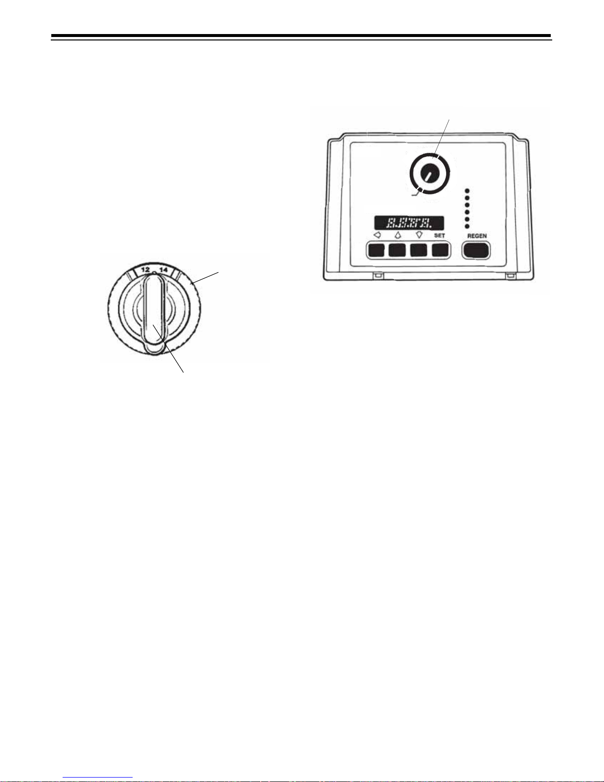
Backwash Dial
Indicator Knob
Figure 6
How to Adjust the Backwash Time
With the indicator knob in the BACKWASH COMPLETE
position (Figure 6), rotate the Backwash Dial
COUNTERCLOCKWISE at least one full turn to cancel
the previous setting. A light clicking will be replaced by
a heavier clicking when the previous setting is
cancelled. T hen, rotate the Backwash Dial to the
desired backwash time. The numb ers are minutes of
backwash per regeneration.
Manual Regeneration
Electricity is use d only to run the control and to rotate
the camshaft. All other functions are operated by water
pressure. Therefore, in the event of a power outage, all
regeneration positions may be dialed manually. Grasp
the indicator knob and turn COUNTERCLOCKWISE to
each regener ation cycle (rotation is muc h eas ier if you
grasp the camshaft with your free hand and turn it at
the same tim e). T he fo ll ow in g cy cle times shoul d be
used for proper regeneration.
BACKWASH - 20 minutes
FA ST R INSE - 10 minutes
960F Control
Cycle Indicator
Figure 7
Programming
This sec tio n co v ers all as pects of programm in g t he
control. The cont rol is shipp ed fr om the fa ctory with
default values for most parameters. These default
values will result in a system capacity of 100 gallons
(1 cubic meter). While the control may operate with
these values, the following parameters mu st b e
change d to meet the actual ope rating condition s :
Refill Controller Value, Brine Draw Rate, and Slow Rinse
Time parameters are not required for 960F operation,
but should be ad justed as instruc ted to ac hiev e the
shortest possi bl e backwash cycle ti me.
Note that some p arameters have a single unit of
measure option . Ot her pa ra me ter s have dual units
such as Ca pa city wh i ch ca n be entered in gallons or
cubic meters. To select which units are active, look for
a comment in the N O T ES colu m n of Tables 1 and 2. It
will reference another parameter that selects which
units are active. For example, parameter P12 (Table 2)
selects U.S. units if it is set to “0” and metric if it is set
to “1”.
6
Page 7

Level I Parameters (Table 1)
Level I parameters are identified as those that have an
LED indicator on the front p an el . Th e gree n in di cator
illuminates next to the name of the active control
settings. The end user has access to all of these
parameters. I n general, pressi n g the down arrow (↓)
button displays the Level I Parameters in the following
order:
• Time of Day
• Time of Regen
• Factor A
• Factor B
• Capacity
If you continue to pr ess the dow n arrow (↓) button, the
parameters start over with Time of Day. Pressing the up
arrow (↑) button displays the parameters in reverse
order. Refer to Table 1 for a desc r ip tio n of th es e
parameters and the available ran ges for each
parameter.
Press the SET button and the far right digit of the
display starts fl ashi n g. If you want to change this
number, press the up arrow (↑) button to increa se th e
number or the do wn arrow ( ↓) button to de creas e the
number. To skip the number without changing, press
the left arrow (←) button. When you reach the far left
digit, pressing the left arrow (←) button will return you
to the far right digit.
Note: If you press and hold either the u p arrow (↑)
button or the down arrow (↓) button for more than one
second, the flashing number will increment or
decrement at the rate of 10 counts per second.
When the num be r is correc t, p ress th e lef t ar row (←)
button. The far right digit sto ps fla shing and the nex t
digit to the left starts flashing. You can only change
the flashing number. Continue changing numbers
until you reach the desired setting. Press the SET
button. The numbers stop flashing and the control
accepts the new setting. After approximately 30
seconds, the control starts alternating the display
between Time of Day and Capacity .
Note: If the new setting is not accepted because it was
outside the allowable range, the old value will be
displayed.
Time of Day
Press the SET button. The display will show the Time
of Day with the minu tes digi t blinking. If you want to
change this number, press the up arrow (↑) button to
increase the num b er or th e d o wn arrow (↓) button to
decrease the number. To skip the number without
changing, press th e lef t ar row (←) button. The first
number stops flashing and the next number starts
flashing. You can only change the flashing number.
When you have reached the far left digit, pressing the
left arrow (←) button returns you to the far right digit.
Continue changing numbers until you each the desired
setting. Pres s the SET button again to enter the valu e .
Time of Backwash
The next value displ ayed is t he Time of Bac kwash. It is
similar to Time of Day programming. It has a default
value of 2:00 a.m. If 2:00 a.m. is acceptable, press the
down arro w (↓) b utto n. If this is no t acce pt ab le, press
the SET button and ch an ge th e num b ers . Press the
SET button again to enter the v alue.
Factor A
Factor A is the next value displayed. The 960F control
uses this val ue to calcula te the system ca pacity . Factor
A must be set to 10 (100 for metric units) for the
960F control to accurately calculate system
capacity. The default value is 10 (100 for metric units).
If the Factor A setting is not cor rect, press th e SET
button and change the value. Press th e SET b utto n
again to enter the new v alue .
Factor B
Factor B is the next value displayed. This value is used
by the control to calculate the pause for the refill cycle.
Becaus e the re fill cyc le is no t requ ired fo r 960 F
operation, Factor B should be set to 0 .2 (0.1 for metric
units). This is the minimum setting and will cause the
control to skip the refill cycle, thereby shortening the
backwash cycle ti me. The default va lue for Factor B is
0.2 (0.1 for metric units). To change Factor B, press the
SET button and change to the correct value. Press the
SET button again to enter the new va lue .
Capacity
Capacity is the next value displayed and is used by the
960F control in combination with Factor A to determine
the capacity of the filter. The Capacity value should be
set to the actual capacity of the filter expressed as
gallons/100 (cubic meters/10 for metric units).
Example: If the actual filter capacity is 950 gallons,
enter 9.5 for the Capacity setting. The default value for
Capacity is 1.0 (0.1 for metric units). To change the
Capacity setting, press the SET button and adjust the
correct valu e. Press the SET bu tton again to enter the
new value.
At this time, all of the Lev el I par ame ter s are
programed. The display will alternate between the Time
of Day and Capacity if no keys are pressed for 30
seconds. The Capacity value displayed i s the volume
remaining in g allons (cubic me te r s for me tr ic) be fo re a
backwas h is n eed ed .
7
Page 8

Note: The 960F control uses Factor A and Capacity
settings to calculate the actual system capacity. If the
actual syst em capacity is in exc es s of 99 99 ga llo n s
(99.99 cubic meters) the control will display 9999
(99.99) until the water usage has dropped the
remaining capacity below that number. When water is
Table 1 - Level I Programming Parameters
flowing through the system, the colon in the Time of
Day disp lay wi ll blink.
To complete the initial programming of the 960F,
proceed to the Level II Para met e rs.
Parameter
Name Description
Time of day
P1
P2
P3 Factor A
P4 Factor B
P5
AM or PM
Time of d ay of
backwash
Capacity of
unit
Range of
Values
1:00 to 12:59
00:00 to 23:59
1:00 to 12:59
AM or PM
00:00 to 23:59
3 to 250
30 to 2500
0.2 to 51.0
0.1 to 25.5
0.1 to 140.0
0.01 to 14.00
Minimum
Increments
1 None Hour: minute
1 2:00 AM Hour: minute
1
10
0.2
0.1
0.1
0.01
Default
10
100
0.2
0.1
1.0
0.1
Cubic Meters/
Units of
Measure
U.S.
Metric
U.S.
Metric
Gallons/100
10
Notes
Range depends on value selected for
P13. Enter the current time.
Range depends on value selected for
P13. Skip this parameter to accept the
default or enter a new time.
Unit of measure depends on value
selected for P12. Set to 10 (10 0 for
metric units) for proper operation.
Unit of measure and default depends
on value selected for P12. Set to .5
(.1 for metric units ) for proper 960i
operation.
Unit of measure depends on value
selected for P12. Enter the unit
capacity in gallons/100 (cubic meters/
10 if metric units).
8
Page 9
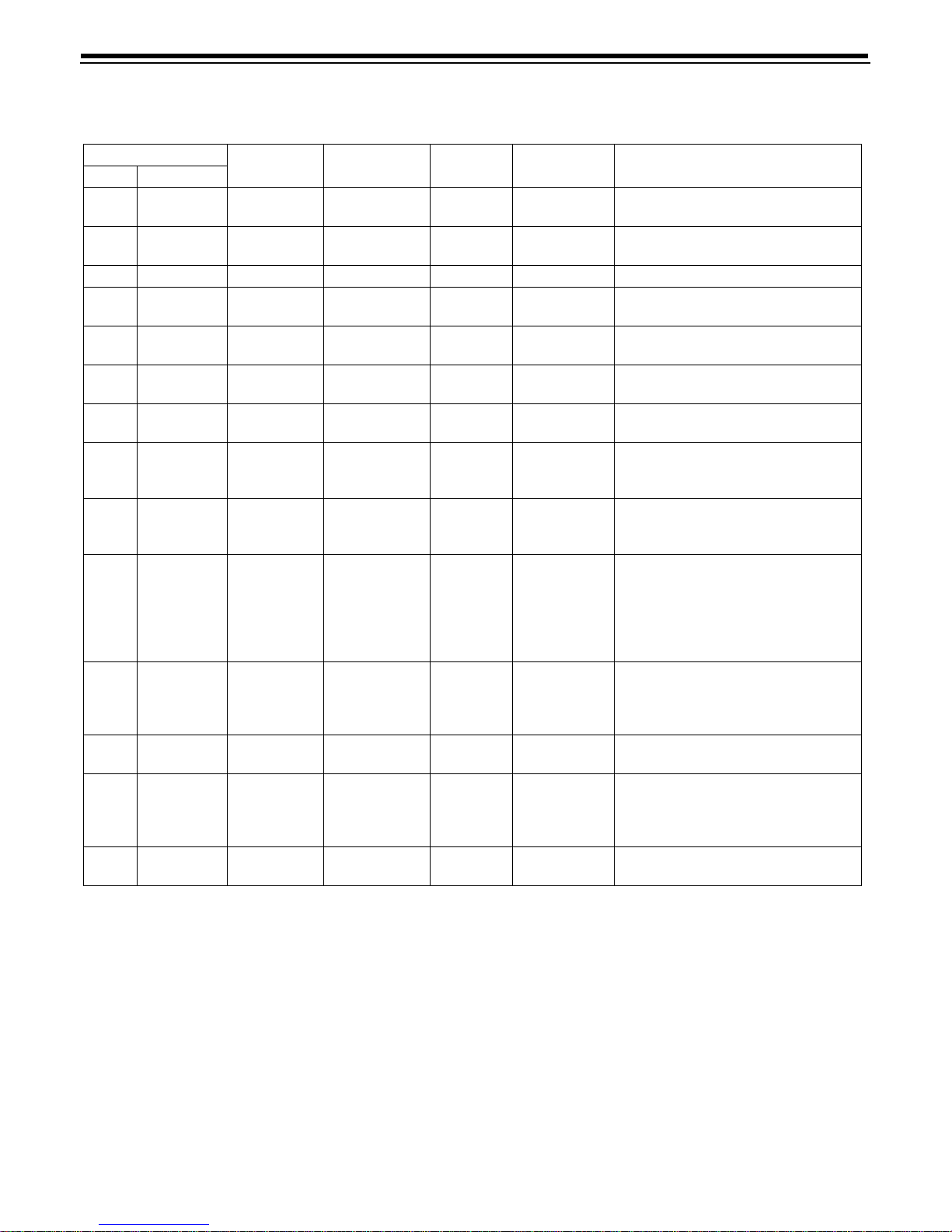
Table 2 - Le ve l II Programming Par a me ters
Parameter
Name Description
Refill Con t rol
P6
P7
P8 Not used NA NA NA NA NA
P9
P10
P11
P12
P13 Clock mode 0 to 1 1 0
P14
P15 Reserve type 0 to 3 1 0
P16
P17
P18
P19
Value
Brine draw
value
Backwash
time
Slow Rinse
time
Fast Rins e
time
Units of
measure
Calendar
override
Fixed r ese rv e
capacity or
initial average
value
Operation
type
Factor B/
Capacity
Factory
defaults
Range of
Values
1 to 99 1 99
1 to 99 1 99 Set to 99 for 960F operation.
3 to 30 1 14 Minutes
8 to 125 1 8 Minutes Set to 8 minutes for 960F operation.
2 to 19 1 9 Minutes
0 to1 1 0
0 to 30 1 0 Days
0 to 70 1 30
0 to 1 1 4 Set to 4 for 960F operation.
0 to 1 change
lock out
0 to 3 1 99
Minimum
Increments
10
Default
Units of
Measure
Percent of
capacity
Set to 99 for 960F operation. Skip for
Enter the desired backwash time in
minutes. Skip for default.
Enter the desired fast rinse time in
minutes. Skip for default.
0=U.S., 1=Metric. Skip thi s p ara me te r
to accept U.S. or enter 1 for Metric.
0=12-hour cloc k, 1=24-hour clock. Skip
this parameter for a 12-hour clock or
enter 1 for a 24-hour clock.
0=no calendar override. Skip this
parameter for no calendar override or
enter a value.
0=va ri able rese rve, 1= f i xed rese r ve ,
2=variable reserve with immediate
backwash, 3=fixed reserve with
immediate backwash. Skip this
parameter to accept th e default or ente r
a different reserve type.
Description depends on the value
entered for P 15. Skip this par a mete r to
accept the default or enter a different
0=none, 1=Factor B/Capacity change
locked out. Skip this parameter to
accept the default or enter 1 to lock out
Factor B/capacity change.
Loads in factory default values.
Do not change this parameter.
Notes
default.
value.
Level II Parameters
The Level II parameters are P6 through P19 in Table 2.
The Home Owners Manual for this product does not
mention these parameters, so the end user does not
normally have access to these values. T o access Level
II Parameters, simultaneously press and hold the down
arrow (↓) and up ar row (↑) button for three seconds.
If th e c on trol was alt ern at in g b et we en T ime o f Da y a nd
Capacity when the above button sequence is entered,
the display shows P1. If a diff e rent Level I Parameter
was displayed, t h e di spl ay, shows the “P” number for
that parameter . Refer to T able 2 to find the “P” number
associated with each parameter.
Use the up arrow (↑) button or the down arrow (↓)
button to move from one para met er to the next. Th e
display cycles through the “P” numbers shown in
T ables 1 and 2. When you reach P19, the display will go
back to P1.
When the parameter number you want to change is
displayed, pres s the l eft arr ow (←) button to display the
data assigned to that parameter . Press the SET button
9
Page 10

and the far right digit on the display star ts flashi ng. If
you want to change this number , press the up arrow (↑)
button or the down arrow (↓) butto n. To skip the
number without cha ng ing, press the le ft arrow (←)
button. When the numb er is correct, press the SET
button. The numbers stop flashing and the control
accepts the new setting. If the new setting was not
accepted, the dis p la y wi ll s ho w the previous setting.
Refer to Table 2 for allowable values for that parameter .
To change or view other parameters, press the left
arrow (←) button to have the display show “P”
numbers. Now use the up arrow (↑) button or the down
arrow (↓) button to move to the parameter number you
wish to change.
To exit the Level II programming mode, simultaneously
press a n d hold the do wn arrow (↓) and up arrow (↑)
buttons for three seconds, or wait 30 seconds without
pressing a button . The co ntrol starts alternating the
display between Time of Day and Capacity.
Refill Control
The Performa Valve with the 960F control is designed
for use as a three cycle filter valve and does not include
a refill control. However, the software program used in
the 960F control is also used for the five cycle softener
control, and requires a refill controller value to calculate
how long to pause the cam shaft in the refill position. In
general, a small refill control value results in a long
pause, and a larg e refill control value results in a s hort
pause. For 960F operation, the refill Control Value
should be set to 99 to avoid delays during backwash.
The default value for Refill Control Value is 99.
Brine Draw Value
Brine Draw V alue P7 is used to calculate the amount of
time required for the b ri ne draw cycle. Becau s e the
960F does not require a brine draw cycle, the Brine
Draw Value should be set to 99 to avoid delays during
backwash.
• This control does not use parameter P8. No entry is
needed for this parameter.
Backwash Time
Parameter P9 is used to set the b ack wash time in
minutes. The default in P9 is 14 minutes. If a different
backwash time is desired, press the SET button and
enter a new value.
Slow Rinse Time
Parame ter P 10 Slo w Ri n s e Time is used to calculate
how long to pause the cam s haf t fo r the slow rinse
cycle. For 960F operation, t he Sl ow Rinse t ime should
be set to 8 minutes to avoid de la ys du r i n g backwash.
The default value for Slow Rinse Time is 8 minutes.
Fast Rinse Time
Parameter P11 determines the fast rinse time. The
default value is 9 minutes. If a different fast rinse time is
desired, press the SET button and enter a n ew val ue.
• Parameter P12 selects the units of measure. Be
sure that this is set to the corre ct value before
entering any data for parameters P3, P4, or P5.
• Parameter P13 selects the clock display mode. If
the 12 hour m ode is selected, a PM ind icator is
used. If the 24 hour mode is selected, the indicator
is not used.
• Parameter P14 is used to set the calendar override
feature. The default value is zero. If set to zero, the
feature is disabled. Refer to Calendar Override for
more inform ati on on the calendar overr id e feature.
• Parameter P15 selects a varia ble r ese rve type , 0 to
3. For more information on r eserve options, re fer to
Reserve Options.
• Par ame ter P 16 is used to calculate the in it ial
average d aily water usage valu es . T he co ntr ol
multiplies the to tal cap acity by the percentage
entered for Parameter P16 and uses that value as
the initial average daily usage for each day of the
week until water usage establishes new averages.
The default is set for 30% of the capa city. In most
installatio n s this is acce ptable.
• Parameter P17 has be en preset to 4. Do no t
change this setting. P17 must be set to 4 for
proper 960F operation. Improper backwashes will
occur if P1 7 is set to som ething other than 4.
• Parameter P18 allows the ins tall er to lock the
Factor B and Ca pa city values so they cannot be
changed. When Parameter 18 is set to 1, those two
settings can only be viewed when the control is in
the Level II mode. The settings will b e sk ip p ed
when the control is in the Level I mode. When
Parameter 18 is set to zero, the Fa ctor B and
Capacit y ca n be view ed and changed in ei th er
Level I or Level II.
• Parameter P19 is used at the facto r y t o en ter
default va lues. T his parameter does not need to
be changed. Using this parameter will erase the
values for all other pa ram eters and replace them
with default values. P19 should be set at 99 and
should not be changed.
10
Page 11

Regeneration
When the control begins a regeneration, the display will
alternate b etween Time of Day and Regen Time
Remaining . The Regen Time Remaining is sh ow n in
minutes. The control will sta r t and stop an int ernal
moto r which drives t h e cam gear through the vario us
backwash positions. The control uses the information
entered in the parameters sh own in Table 2 to
determine how long each part of the cycle should last.
If power fails d ur ing a regene r atio n cy cle, the cycle
completes normally when the power is restored.
Note: The REGEN button is only activ e when the
display is alt ernating between Time of Day and
Capacity. When programming Level I or II param eters,
the REGEN button is not active.
The Regen Time Remaining will continue to count
down until the cam gear r eaches the Ser v ice positi o n.
Manual Regeneration
To initiate a manual regeneration, press the REGEN
button. This button is located on the front of the control.
When you press the REGEN button, the control
performs a full regeneration of the filter.
If you press thi s button again more than one minu te
afte r rege neration begins, but bef ore the
regeneration is complete, a second regeneration
will start when the first r egeneratio n is finished. The
display will freeze and only show the Regen Time
Remaining as an indication that the sec on d
regeneration wil l be performed. When the first
regeneration is com pl ete, th e s econ d o ne wi ll begin
and the display will alternate between Time of Day and
Regen Time Remaining.
Automatic Regeneration
There are two ways to have the control automatic ally
initiate a regeneration: calendar override or normal
metered water usag e.
Calendar Override
This feature is set in parameter P14. It can be set for 1
to 30 days. If it is set to zero, this feature is disabled.
When this feature is active, the control keeps track of
the number of days since the last backwash and when
that number equals the value set in P14, a backwash is
automatically started at the Time of Backwash set in
P2.
Normal M etere d Wat er U sa ge
The control compares the water usage to the
calculated volume capacity of the system. The control
uses the Capa city p ar am eter P5 and the Factor A
paramet er P3 to calcu la te th e volu m e capacity of the
system. It also uses a reserve value to determine if a
backwash is necess ar y. If t he water usage s ince the
last backwas h is g reater than the s yste m capacity
minus the rese rve , a b ack wash is needed.
Note: If the water usage exceeds 150% of the syste m
capacity between backwashes, the control will
automatically call for a second backwash the next day
even if no water used.
Reserve Options
There are two type s of reserve option s for this control:
fixed reserve and historical water usage pattern. They
are selected with parameter P1 5.
Fixed Rese rv e
When the fixed reserve is selected, the control
multiplies the maxi mum system capacity by the
percent value set in parameter P16 and uses the result
as a reserve.
Water Usage Pattern
The other reserve op tion allows the contr ol to adjust the
reserve based upon the historical water usage pattern
of the system. The control k eeps track of the water
usage for each day of the week and uses that day’s
avera g e usage mult iplied by 1.2 as the r eserve for that
day. Every day at the Time of Backwash, the control
recalculates the day’s average water usage. If less than
10% of a day’s average water u s age is u sed, the
control will not change the day’s average. If more than
twice the da y’s average is used , the control uses the
actual usage in the reserve calculation.
Since a new installation has no history of water usage,
the control multiplies the percent of capacity value set
in parameter P16 by the total system capacity to
determin e st ar ting av erage for each day of the wee k.
The factory set default value for P16 is 30 which means
that 30% of the tota l sys tem capacity is used for t he
starting average for each day.
Program parameter P15 is also used to select whether
the control wa its unt il the Time o f Backwash set in
paramet er P2 to start a backwash, or if the co nt rol
should beg in a ba ckwash immed iate ly when the
capacity rema ining is les s than th e rese rve.
11
Page 12
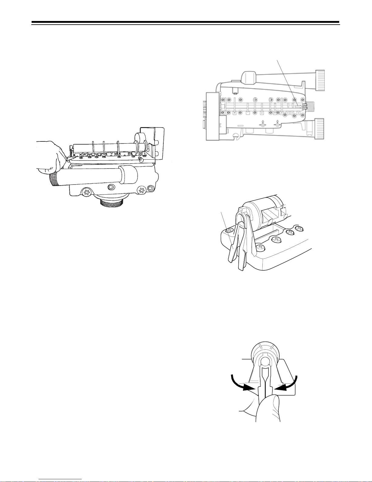
Removing the Valve Assembly for
Servicing
1. Unplug t he p owe r c ord.
2. Shut off water supply or put bypass valves into
bypass position.
3. Remove cover and with screwdriver, relieve tank
pressur e by pushing ope n valve No. 7 (r ear flapper )
on control as shown (Figure 8).
Figure 8
Indicator Arrow
Figure 9
Yellow Camshaft
Clip
4. When used with a globe valve bypass, loosen and
detach the inlet, outlet, brine an d drain lines from
the valve. If using the 1265 bypass, loosen and
remove valve fr om bypass as well as loosening and
removing the brine and drain lines.
5. Unscrew ( co un terclockwise) and remov e valve
from tank.
6. To replac e th e con trol valve , reve rse th e ab ove
procedure.
Removing 440i for Servicing
1. Unplug t he p owe r c ord.
2. Remov e the co v e r.
3. Align the indic ator arrow on the rea r of the
camshaft with the top of the rear hoo p of the top
plate (Figure 9).
Figure 10
4. Remove the yellow camshaft clip, located at the
rear of the camsh af t (Fig ure 10) to remove the
camshaft. Push the two end s of the clip togeth er
(Figure 1 1) to remove the clip from the bac k.
Figure 11
12
Page 13
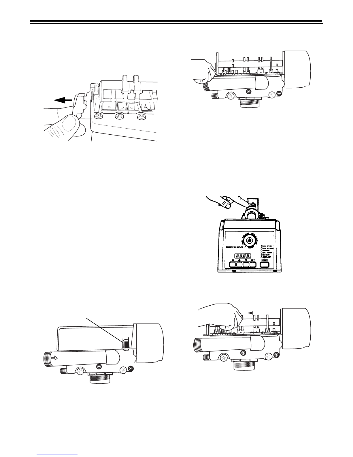
5. Remove the yellow camshaft clip from the rear top
plate hoop (Figure 12).
Figure 12
6. Diseng ag e the front of the camshaft from the
output gear of the control.
7. Remov e the timer locking pi n an d lift the co nt ro l
straight up and off of the valve.
8. Reverse the above procedures to reinstall the
camshaft and control.
Figure 14
5. To remove the camshaft or to reinstall it, the arrow
on the shaft must be pointing at the line on the rear
“hoop” of the top plate. This occurs when the
indicator knob is rotated to the refill position. Press
down on the b ack o f the camshaft to disengag e it
from the rear “hoop” of the top plate, (Figure 15).
Slide the cam s h af t bac k to dise n g age it from the
timer, (Figure 16).
Removing the 940F and 960F Controls For
Servicing
Complete the following steps to remove the 940F and
960F control for servicing:
1. Unplug the wa ll -mount transfo rmer.
2. Shut of f the water supply o r put the bypass valve (s)
into bypass position.
3. Remove the rear cover by depressing the two tabs
provided on the cover, (Figure 1 3). Lift the front of
the cover and remo ve to exp ose the valve body.
Tab
Figure 15
Figure 16
Figure 13
4. Relieve syst em pressur e by opening t he Backwash
Drain Valve (the seventh valve back from the
control) with a screwdriver, (Figure 14).
6. Disconne ct the turb ine probe from the turbine
assembly.
7. Lift the control off the valves, Figure 17. To r eplace
the control, reverse the above procedure. Note that
the camshaft needs to be positioned correctly
before it can be inserted into the back of the
13
Page 14
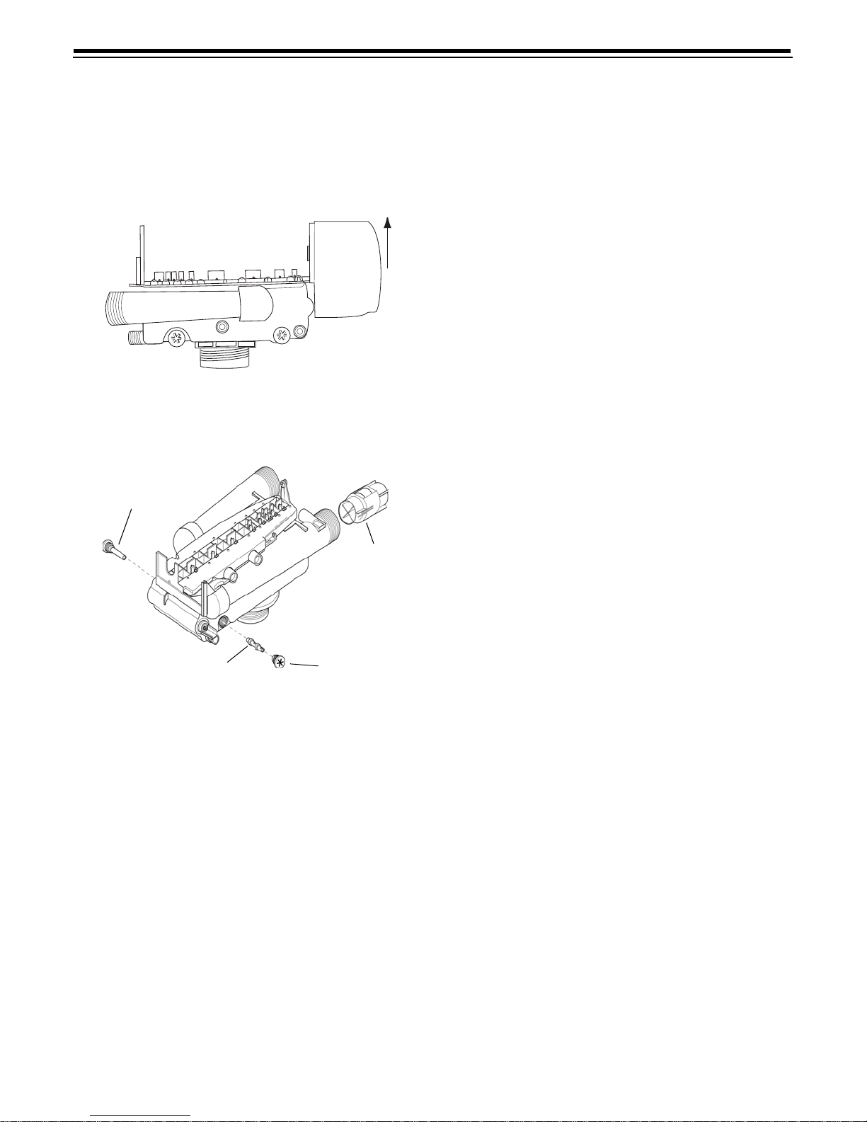
control. There is a loca tin g rib on the camshaft.
Position the rib on the top of the shaft and slide the
camshaft into the control. Push up on the end of
the camshaft, furthest from the timer, snapping it
into place.
Figure 17
Preventive Maintenance
Injector Screen
Turbine
instances, the turbine wheel of the water meter can
collect small particle s of o xid ized iron, eventually
preventing the wheel from turning .
1. Shut off the water supply or put the bypass valve(s)
into the bypass posit ion .
2. Reli eve pressure by opening the Back wash Drain
Valve (the seventh back from the control) with a
screwdriver (Figure 14).
3. Loosen and remove the pipe/ tub e adapters or
1265 bypass from the inl et and ou tlet o f the valv e
body.
4. Using a needle-nose pliers, remove the turbine
from the outlet housing. Grasp one of the four
vanes of the outer gland and pull straight out to
remove turbine asse mb ly from the outlet of the
valve (Figure 18).
5. Caref ully rem o ve the tu rbine wheel from the
housing. Use a toothbrush to lightly scrub the iron
off the magnet. Iron buildup on the surfaces can be
removed by s oa ki ng the wh e el in a mi ld s o di um
hydrosulfite (such as RoVer*) solution for a few
minutes. Flush thoroughly with water.
6. Carefully reinstall the turbine wheel into the turbine
cage housing. Make sure that the shaft of the wheel
seats into t he be arin g of th e cage . Rea sse mble the
turbine cag e an d check that the wheel rotates
freely.
Injector
Cap
Figure 18
Water Meter Maintenance
Note: A water meter is used only with the 960F control.
If you are using the 440i or 940F control, this section
does not pertain to your conditioner.
The metering device used with the 960 dema nd
controls may requ ire simp le maintenance. In rare
7. Reinst all the turbine cage into the outlet o f the
valve.
8. Reinstall the pipe/tube adapters or 1265 bypass to
the inlet and outlet of the valve.
9. T urn on the water supply or put the bypa ss valve(s)
into the service position and purge the air out of the
system.
To ch eck for proper meter op eration, open a
downst ream faucet and observe the water flow
indic ation on the co nt rol display.
14
Page 15
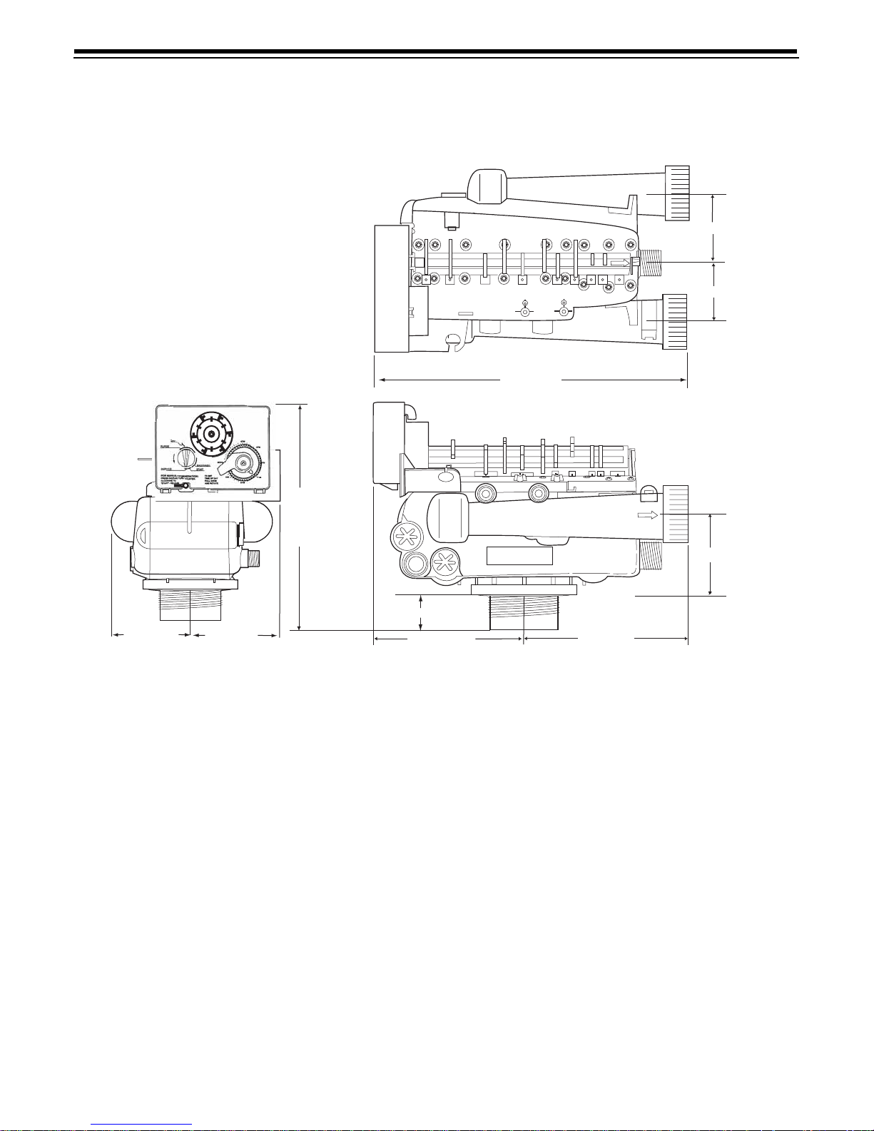
Specifications
263/440i Drawings
1
6
2
5
3
4
Inlet
2.5 inch (63 mm)
Drain
2.5 inch (63 mm)
Outlet
11.59 inch (294 mm)
8.74 inch (222mm)
2.88 inch (73 mm)
1.356 inch (34 mm)
3.37-inch (86 mm)
3.66-inch (93 mm)
5.76 inch (146 mm)
5.82 inch (148 mm)
Hydrostatic Test Pressure . . . . . . . . . . . . . . . . . . . . . . . . . . . . . . . . . . . . . . . . . . . . . . . . . . . . . . . . 300 p si (20 .6 9 bar )
Working Pressure. . . . . . . . . . . . . . . . . . . . . . . . . . . . . . . . . . . . . . . . . . . . . . . . . . . . . . . . 20-125 psi (1.38 - 8.62 bar)
Standard Electrical Rating. . . . . . . . . . . . . . . . . . . . . . . . . . . . . . . . . . . . . . . . . . . . . . . . . . . . . . . . . . . . . . 115V 60 Hz
Optional Electrica l Rating . . . . . . . . . . . . . . . . . . . . . . 115V 50 Hz, 230V 50 Hz, 200V 60 Hz, 24V 60 Hz, 24V 50 Hz,
100V 60 Hz, 100V 50 Hz, 12V 50 Hz/transformer, 12V 60 Hz/transformer
Electrical Cord (standard rating) . . . . . . . . . . . . . . . . . . . . . . . . . . . . . . . . . . . . . . . . . 60 inch (1.5 m) 3-wire with plug
Pressure Tank Thread . . . . . . . . . . . . . . . . . . . . . . . . . . . . . . . . . . . . . . . . . . . . . . . . . . . . . . . . . . . . 2 1/2 inch-8 male
Riser Pipe Diameter Required . . . . . . . . . . . . . . . . . . . . . . . . . . . . . . . . . . . . . . . . . . . . . . . . 1.050 inch OD (26.7 mm)
Riser Pipe Length . . . . . . . . . . . . . . . . . . . . . . . . . .1-1/8
± 1/8 inches (31.8 mm) highe r than the top of mineral tank
Standard Connection . . . . . . . . . . . . . . . . . . . . . . . . . . . . . . . . . . . . . . . . . . .1-inch (25.4-mm) copper tube adapters
Optional Connections . . . . . . . . . . . . . . . . . . . . . . . . . . . . . . . . .3/4-inch, 22-mm, and 28-mm copper tube adapters
3/4-inch BSPT , 1-inch BSPT , 1-inch NPT brass pipe adapters
3/4-inch, 1-i nch, 25-mm CPVC tube adapters
Drain Line Connection . . . . . . . . . . . . . . . . . . . . . . . . . . . . . . . . . . . . . . . . . . . . . . . . . . . . . . . . . . . 3/4-inch NPT male
Optional Bypass Valve. . . . . . . . . . . . . . . . . . . . . . . . . . . . . . . .Rotating handles, full 1-inch porting, reinforced Noryl
Control Module, Tank Adapter. . . . . . . . . . . . . . . . . . . . . . . . . . . . . . . . . . . . . . . . . . . . . . . . . . . . . . .Reinforced Noryl
Rubber Goods . . . . . . . . . . . . . . . . . . . . . . . . . . . . . . . . . . . . . . . . . . . . . . . . . . Compounded for co ld wa t er service
Program Clock (Timer). . . . . . . . 440i: Available in 6 - or 7-day English, Ge rman, French, Italian, Spanish, Japanese
940F: Availa ble in 7 - or 12-day English, Ger man , French, Italian, Spanish, Japane se
960F: Available in English, German, French, Italian, Spanish, Japanese
Internal Backwash Controllers. . . . . . . . . . . . . . . . 7- through 14-inch (17.8- though 35.6-cm) diameter media tanks
All sizes to flow 4.5 gpm/sq ft (183 L/m/m
2
) of bed area. For tank sizes above 14 inches in diameter ,
use an external flow control.
15
Page 16
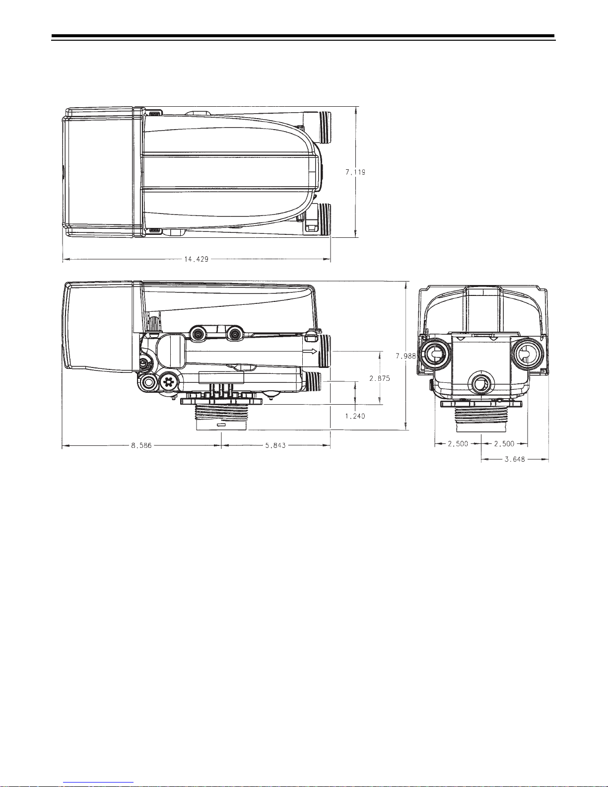
263/900 Series Drawings
16
Page 17
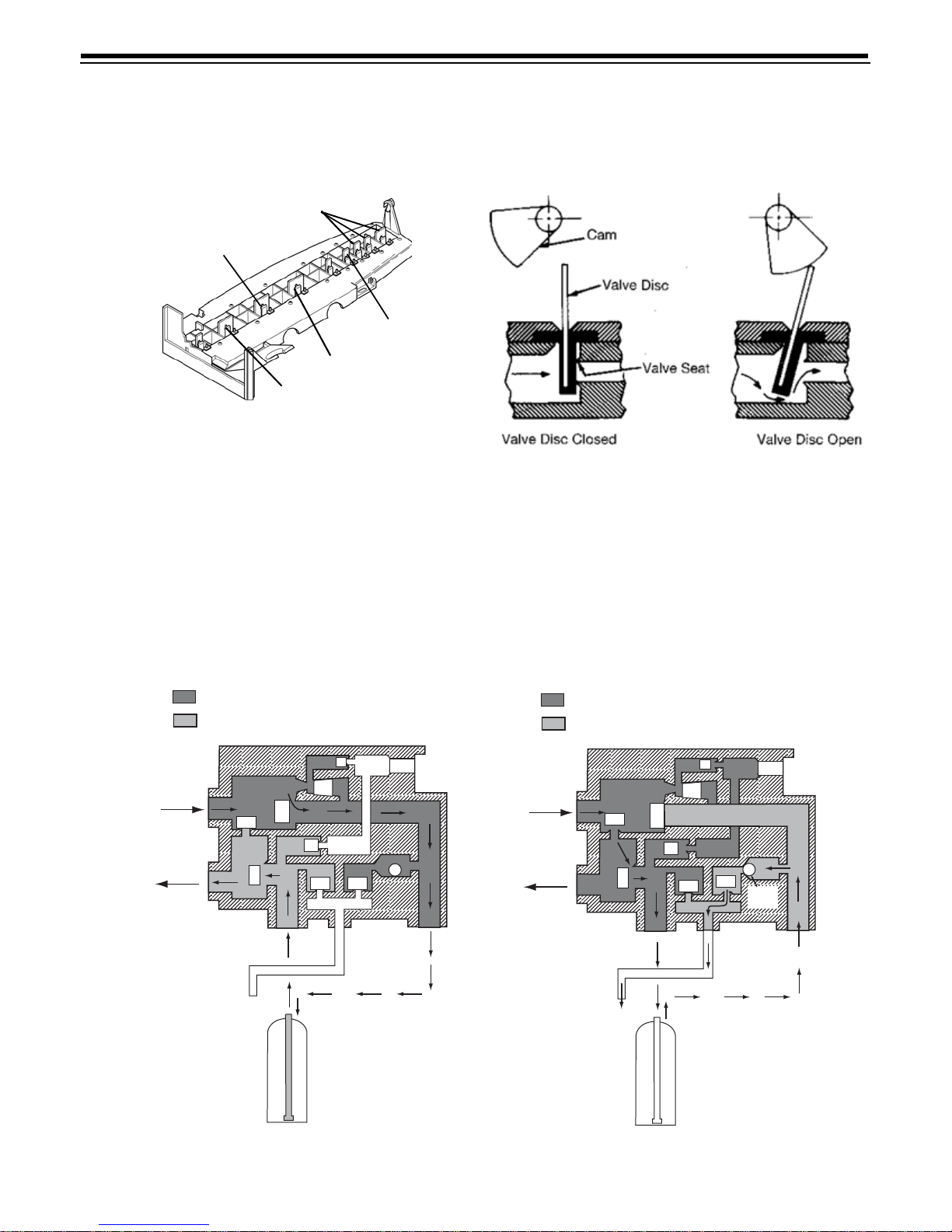
Control Valving Identifications
7 Backwash Drain Valves
3 Inlet Valve
6 Rinse Drain
Valve
4 Outlet Valve
2 Bypass Valve
Flow Diagrams
Valve Disc Operation
1 Treate d Water Posit i on
Untreated Water
Treated Water
Plug
3
5
6
Valve
No.
1 - Closed
2 - Closed
3 - Open
4 - Open
5 - Closed
6 - Closed
7 - Closed
Inlet
Outlet
2
4
Drain
Mineral Tank
2 Backwash Pos i t ion
Untreated Water
Treated Water
1
1
Plug
Inlet
7
Outlet
Drain
3
2
4
Valve
No.
1 - Open
2 - Open
3 - Closed
4 - Open
5 - Open
6 - Closed
7 - Open
Mineral Tank
1
Plug
5
6
Plug
7
Backwash
Flow
Control
17
Page 18
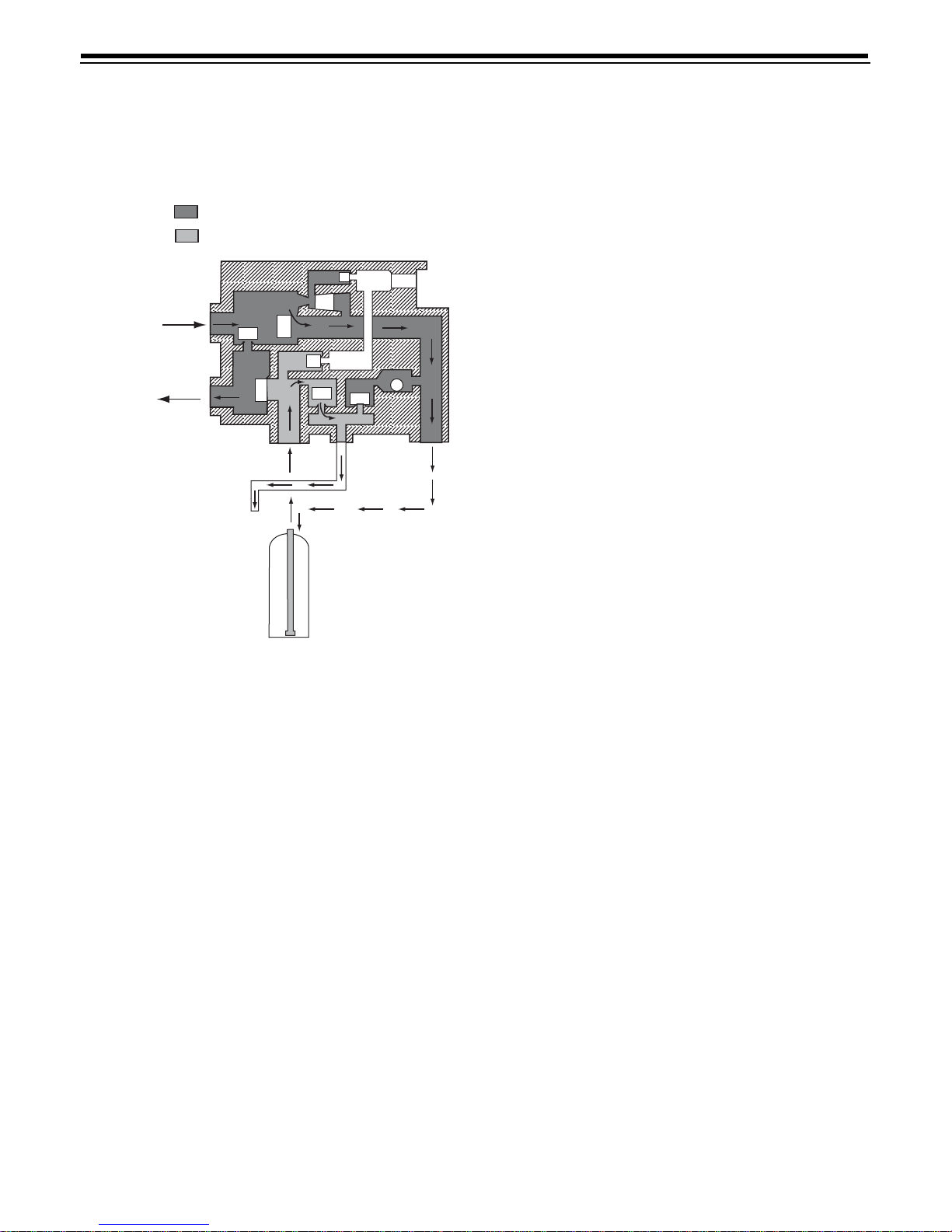
3 Fast Rinse Position
Untreated Water
Treated Water
Valve
No.
1 - Closed
2 - Open
3 - Open
4 - Closed
5 - Closed
6 - Open
7 - Closed
Inlet
Outlet
Drain
3
2
4
Mineral Tank
1
Plug
5
6
Plug
7
18
Page 19
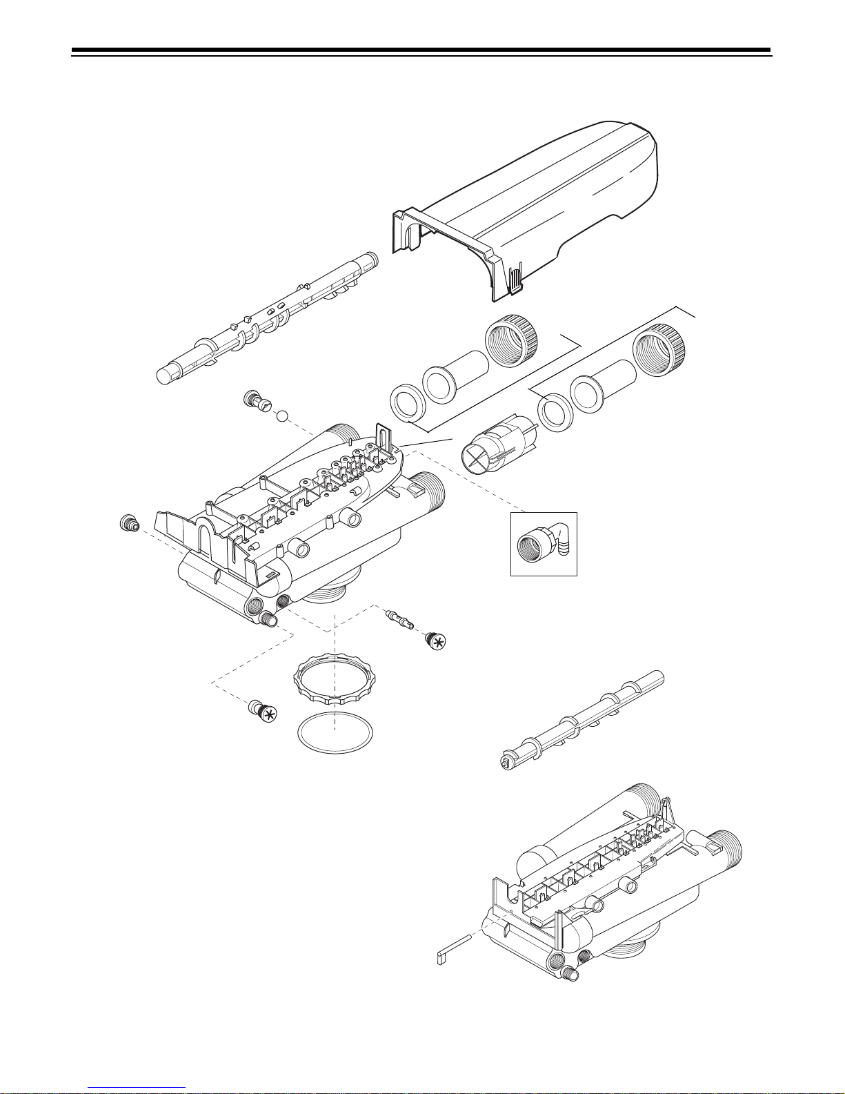
Performa Valve Replacement Parts
Performa Valve
5
6
7
12
18
15
15
17
16
11
8
1
14
10
13
9
4
3
2
19
Page 20

Parts List
Part
Code
No. Description Qty. Code
10 1030334 Plugged Brine Refill Control 1
1 1035807 Valve Assy, w/o Flow Controls (940F, 960F) 1 11 1002449 Drain Fitting Elbow (3/4” hose barbed) 1
2 1035606 Valve Assembly, w/o Flow Controls (4 40i) 1 12 1000226 Cap Assembly 1
3 1031391 Timer Locking Pin 1 13 1010429 O-Ring 1
4 1035624 440i Filter Camshaft (Grey) 1 14 1035622 T ank Ring 1
5 103038 0 940F, 960F Fil ter Camshaft 15 Plumbing Adapter Kit s: 1
6 Drain Control Assembly: 1 1001606 3/4-inch Copper Tube Adapter Kit
100020 9 No. 7 (1.2 gpm; 4.5 Lpm) 1001670 1-inch Copper Tube Adapter Kit
100021 0 No. 8 (1.6 gpm; 6.1 Lpm) 1041210 1-1/4-inch copper Tube Adapter Kit
1000211 No. 9 (2.0 gpm; 7.6 Lpm) 1001608 22-m m Copp er Tube Adapter Kit
1000212 No. 10 (2.5 gpm; 9.5 Lpm) 1001609 28-mm copper Tube Adapter Kit
100021 3 No. 12 (3 .5 gpm; 13.2 Lpm) 1001613 3/4-inch CP VC Tube Adapt er Kit
1000214 No. 13 (4.1 gpm; 15.5 Lpm) 1001614 1-inch CPVC Tube A dapter Kit
100021 5 No. 14 (4.8 gpm; 18.2 Lpm) 1001769 3/4-inch NPT Plastic Pipe A dapter Kit
7 103050 2 Ball, Flow Cont rol 2 1001603 1-inch NPT Plastic Pipe Adapter Kit
8 1032978 Plugged Injector Assembly 1 1001604 3/4-inch BSPT Plastic Pipe Adapter Kit
9 1000218 Inje c tor Cap Assembl y 1 1001605 1-inc h BSPT Plastic Pipe Adapt er Kit
16 1 0 33 444 Turbine As se mb ly (9 60 F on ly) 1
17 1001580 Spring, Flapper Valve
*Valve Disc Kit:
* 10000 62 I-Lid Cover 1
Part
No. Description Qty.
1001611 3/4-inch BSPT Brass Pipe Adapter Kit
1001610 1-inch NPT Brass Pipe Adapter Kit
1001612 1-inch BSPT Brass Pipe Adapter Kit
1041174 Standard
1041175 Severe Service
20
Page 21
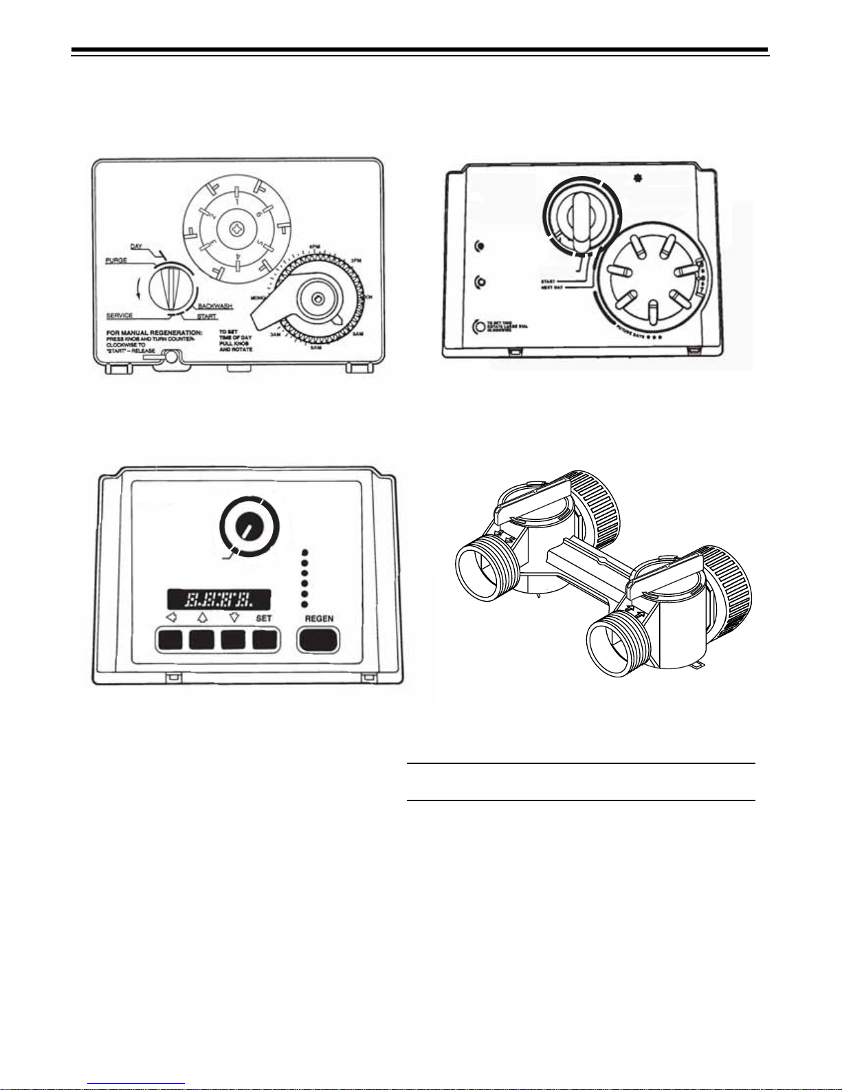
Tim
e of Day
Tim
e of Regen
Factor A
Factor B
Capacity
Regen Tim
e
Remaining
REGENERATION COMPLETE
F
A
S
T
R
I
N
S
E
B
A
C
K
W
A
S
H
PM
Perform
a
Filter
T
M
440i Control 940F Control
TM
Performa Filter
FOR MANUAL
BACKWASH
ROTATE POINTER
COUNTER
CLOCKWISE TO
START POSITION
BACKWASH COMPLETE
TO ADJUST BACKWASH
MINUTES, ROTATE
SMALL DIAL COUNTER
CLOCKWISE.
DO NOT ADJUST
DURING BACKWASH
12
960F Control 1265 Bypass
A
P
Y
B
E
S
N
I
R
T
S
A
F
S
E
R
V
I
C
E
S
S
B
A
C
K
W
A
S
H
TO SET
REGENERATION
DAYS PRESS PINS IN
S
S
A
P
Y
B
34
Part
Code
1
2
3
4 1040930
* 1000811
*
*
*Not Shown
No. Description Qty.
440i Control (6 day or 7 day)
940F Cont rol (7 day or 12 day)
960F Control
1265 Bypass
Transformer (440i, 460i, 960):
1000907
1034264
Transformer Extension Cord
15 feet (4.6 m)
Y-Splitter (run 2 units from 1 tran sformer)
1
1
1
1
1
1
1
21
Page 22
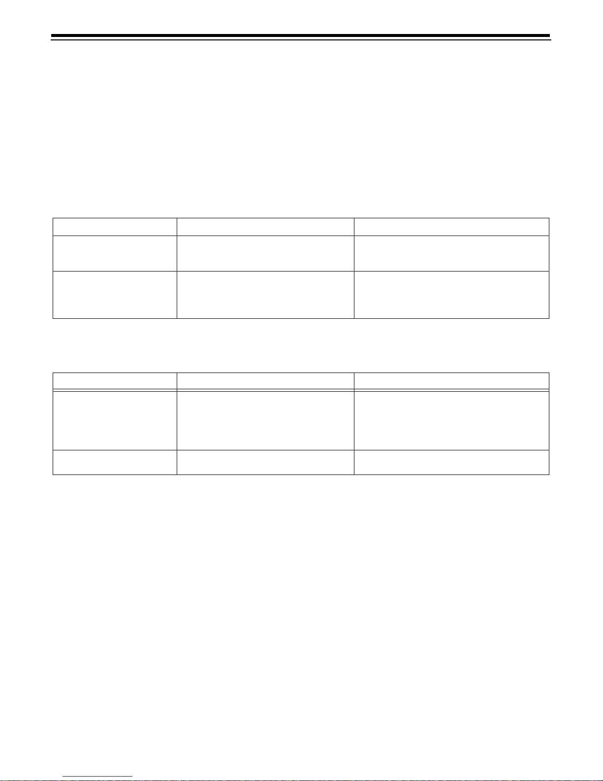
Troubleshooting
The technology upon which the Autotrol Perf orma
control valve is based is well established and proven in
service over many years. However , should a pr oblem or
question aris e re gard ing the o pe r atio n o f the s y st em,
the control can v ery eas ily be se rviced. For parts
mentione d, refer to ex pl od ed v iew s in the
Replacement Parts section of this manual.
Valve Troubleshooting
Problem Possible Cause Solution
1. Control backwashes at
excess ively low or high rate.
2. Untreated water leakage
during service.
a. Incorrect backwash controller used.
b. Foreign matter affecting co ntroller
operation !
a. Improper regeneration.
b. Leaki ng of bypass valve !
c. O-ring around riser tube damaged !
440i and 940F Control Troubleshooting
IMPORTANT: Serv ice procedures that r equire the
water pressur e to be rem oved from the system are
marked with a ! after the possible caus e. To remove
water pressure from the system, put the bypass valve
or three-valve bypa s s into the bypa s s po sitio n and
open the backwash drain valve (the seventh valve back
from the control) with a screwdriver. Restore system
water pressure when the service work is completed.
a. Replace with correct size controller.
b. Remove controller and ball. Flush with water.
a. Repeat regeneration making certain that the
correct salt dosage i s set.
b. Replace O-rin g.
c. Replace O-ring.
Problem Possible Cause Solution
1. Control will not regenerate
automatically.
2. Control regenerates at wrong
time of day.
a. Transformer or motor not connected.
b. Defecti ve timer motor.
c. Skipper pins not down on timer skipper
wheel.
d. Binding in gear train of timer.
a. Time set incorrectly. a. Correct time setting according to inst ructions.
a. Connect power.
b. Replace motor.
c. Depress pins for days regeneration required.
d. Replace timer.
22
Page 23
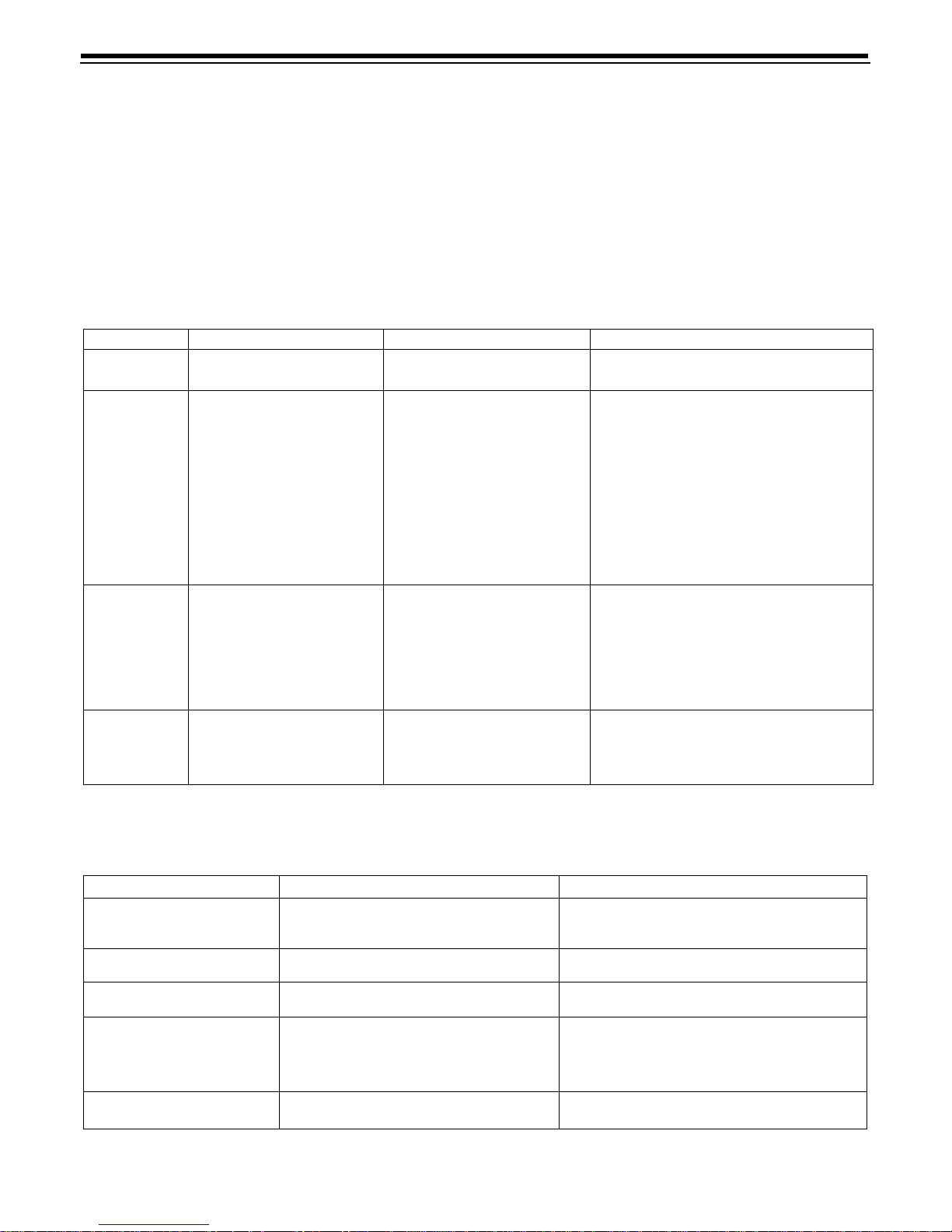
960F Control Troubleshooting
Alarms
The Model 960 continuously monitors itself and sounds
an alarm if it detects something wrong. The alarm is a
beep that is on for o ne s eco nd an d th en o ff for nine
seconds. When the alarm sounds, the display shows
the letters “Err” wi th a numb er from 1 to 4. The tab le
Model 960 Alarms
Indication Description
Err 1 Electronics Failu re
Improper start of
Err 2
regeneration (limit switch
closed when it should be
open).
Improper finish of
Err 3
regeneration (limit switch
open when it should be
closed).
Improper control settings
Err 4
(one or more setti ngs out of
the allowable range).
Control settings need
reprogramming.
Valve camshaft has been
manually rotated during a
regeneration.
Valve camshaft has been
manually rotated out of
“regeneration complete”
Faulty motor.
Faulty motor drive.
Faulty s witch.
Valve camshaft has been
manually rotated out of
“regeneration complete”
Faulty motor.
Faulty motor drive.
faulty switch.
One or more se ttings out of
the allowable range.
below lists the Err numbers, a description of each error,
the cause of the error, and the solutions. T o silence the
alarm, press any button o n the co ntrol. If the error still
exists, th e con trol w ill g o bac k to the alarm condition
after 30 seconds.
Cause
Press any key to load defaul t valu es. Refe r
to “Programming the Model 960 Control”.
Press any key to silence the alarm. (Note:
Alarm automatically clears at “TIME OF
The control will turn the motor on and drive
the camshaft to the proper location.
position.
The control will turn the motor on and drive
the camshaft to the proper location.
position.
Hardness: Adjust range: 3 to 250.
Capacity: Adju st range: 0.1 to 140.0.
Refill c on t rol: Ad ju s t ran g e : 1 to 99.
Brine draw value: Adjust range per Table 2.
Solution
REGEN”.)
Replace the control.
Replace the control.
Replace the control.
Replace the control.
Replace the control.
Replace the control.
Problem Possible Cause Solution
1. Capacity Display stays at 9999
even though there is water
usage.
2. Timer beeps when left arrow
button is pressed.
3. Timer does not respond to
REGEN button.
4. Timer d oes not di splay ti me of
day.
5. Timer does not display correct
time of day.
a. Total system capacity was cal culated to
a. Button is only active in the programming
a. Button is not active in the programming
a. Transformer is unplug ged.
b. No electric pow er at outlet.
c. Defective transformer.
d. Defecti ve circuit board.
a. Outlet operated by a switch.
b. Power outages.
be a value greater than 9999.
mode.
mode.
23
a. As the water usage continues, the remaining
capacity will dr op below 9999 and then other
values will be shown.
a. Refer to the Programming section.
a. Refer to the Regeneration section.
a. Connect power.
b. Repair outlet or us e working outlet.
c. Replace transformer.
d. Replace control.
a. Use outlet not controlled by switch.
b. Reset Time of Day.
Page 24
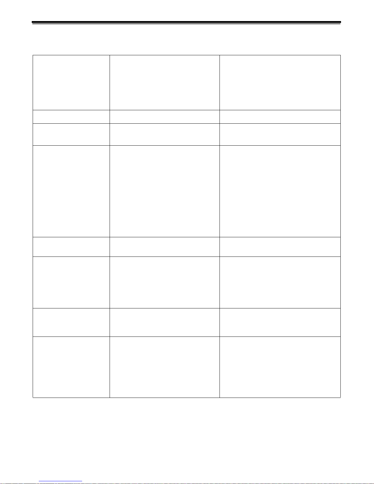
6. No water flow display when
water is flowing (colon does
not blink).
7. Control display is frozen at
Regen Time Remain ing.
8. Control regenerates at wrong
time of day.
9. Timer stalled in regeneration
cycle.
10. Continuous regeneration.
Camshaft does not stop at the
end of regeneration.
11. Control does not regenerate
automatically or when R EGEN
button is depressed.
a. Bypass valve in bypass position.
b. Meter probe disconnected or not fully
connected to meter housing.
c. Restricted meter turbine rotation due to
foreign material in meter !
d. Defecti ve meter probe.
e. Defective circuit board.
a. Back to back regenerations were
requested.
a. Power outages.
b. Time of day set incorrectly.
c. Time of regeneration set incorrectly.
a. Motor not operating.
b. Motor runs backwards.
c. No electric power at outlet.
d. Incorrect voltage or frequency (Hz).
e. Broken gear.
f. Defective switch.
g. Air leak in brine connecti o ns ( pr essure
locked flapper).
h. Binding of camshaft.
i. Water pressure greater th an 125 psi
during regeneration.
j. Defective circuit board .
a. Broken projecti o n on drive gear.
b. Defective switch.
a. Transformer unplugged.
b. No electric pow er at outlet.
c. Defective motor.
d. Broken gear.
e. Binding in gear train.
f. Defective switch.
a. Shift bypass valve into service position.
b. Fully insert probe into meter housing.
c. Remove meter housing, free up turbine and
flush with clean water. Turbine should spin
freely, if not, refer to the Water Meter
Maintenance section.
d. Replace control.
e. Replace control.
a. Refer to the Manual Regeneration section.
a. Reset time of day to correct time of day.
b. Reset time of day to correct time of day.
c. Reset time of regeneration.
a. Replace control.
b. Replace control.
c. Repair outlet or use working outlet.
d. Replace timer and/or transformer with one of
correct voltage and frequency (Hz).
e. Replace control.
f. Replace control.
g. Check all junction points and m ake
appropriate corrections.
h. Remove foreign object obstruction from valve
discs or camshaft.
i. Install pressure regulator to reduce pressure.
j. Replace control.
a. Replace control.
b. Replace control.
a. Connect power.
b. Repair outlet or us e working outlet.
c. Replace control.
d. Replace control.
e. Replace control.
f. Replace control.
12. Control does not regenerate
a. If water flow display is not operative, refer
automatically but do es
regenerate when REGEN
button is depressed.
13. Run out of treated water
between regenerations
b. Incorrect program settings.
c. Defective circuit board.
a. Improper regeneration.
b. Fouled resin bed.
c. Incorrect factor 1 or capacity settings.
d. Restricted meter turbine rotation due to
e. Excessive water usage below 1/5 gallon
to item 5 in this table.
foreign material in meter housing !
per minute.
a. Refer to item 5 in this table.
b. Set new control v alu es. Refer to the
Programming section.
c. Replace control.
a. Repeat regeneration making certain that
correct salt dosage is used.
b. Use resin cleaner.
c. Set to correct values. Refer to the
Programming section in this manual.
d. Remove meter housin g, fr ee up turbine, and
flush with clean water. Turbine should spin
freely, if not, replace meter.
e. Repair leaky plumbing and/or fix tures.
© Copyright 2007 GE Water & Process Technologies
Printed in USA P/N 1227982 Rev. D
 Loading...