


User Manual
AUTO
In Vehicle Brake Tester
STOP
Version 8.18
Maxi

Table of Contents
AutoStop Maxi
User Manual Version 8.18
1. UNPACKING AND FIRST TIME USE ..................................................................................... 2
1.1 Activating your meter ......................................................................................................... 2
2. USE OF BATTERY CHARGER AND CARE OF BATTERY ................................................... 3
3 OPERATION ................................................................................................................................. 4
2.1 Options: Changing & Viewing ........................................................................................... 4
2.2 Test Conditions & Test Area ............................................................................................. 4
2.3 Set-Up in Vehicle ................................................................................................................ 4
2.4 Running the Test ................................................................................................................ 4
2.5 Special Characters ............................................................................................................. 5
2.6 Test Instructions Summary ............................................................................................... 6
3. TEST DATA STORAGE (OPTIONAL) .................................................................................... 8
3.1 Using the Data Logger ....................................................................................................... 8
3.2 Downloading Data .............................................................................................................. 8
3.2.1 Download Instructions ................................................................................................... 8
4. CHECKING SENSORS AND OTHER FUNCTIONS ............................................................. 10
5. CALIBRATION PROCEDURE .............................................................................................. 11
5.1 Return of AutoStop Maxi for Calibration ........................................................................ 11
5.1.1 Packaging ...................................................................................................................... 11
5.1.2 Shipping ......................................................................................................................... 11
5.1.3 Documentation .............................................................................................................. 12
6. TROUBLESHOOTING .......................................................................................................... 12
7. SPECIFICATIONS ................................................................................................................ 12
8. CHANGING PAPER.............................................................................................................. 13
9. CHANGING PRINTER RIBBON ........................................................................................... 14
10. WARRANTY ......................................................................................................................... 15
11. QUICK GUIDE ...................................................................................................................... 16
AutoStop Maxi User Manual Version 8.18 Page 1

1. UNPACKING AND FIRST TIME USE
Congratulations on your choice of an AutoTest Brake Meter. Please take the time to
read this User’s Manual before using the AutoStop Maxi Brake Meter in the field.
Incorrect or inappropriate use of this instrument may void the warranty. Retain the
packing materials for future shipping and transport of the unit for periodic calibration.
Please complete the warranty registration card and post it to AutoTest Products Pty
Ltd, alternatively visit our website www.autotest.net.au and complete your warranty
registration on line. Your warranty registration ensures that you are kept up to date
on any software or hardware changes to your AutoStop Brake Tester. The packing
box of your AutoStop Maxi should contain the following:
1. AutoTest Brake Meter, Model AutoStop MAXI, complete with Pedal Sensor
2. Long strap for restraining Brake Meter Unit Case
3. Battery Charger
4. User Manual
5. Warranty Registration Card
6. Calibration Certificate
7. Interface Cable (download option only)
8. Program Disc (download option only)
1.1 Activating your meter
Initially, each meter is locked prior to its shipment. So, before you can perform any
brake tests, you must first activate your meter.
Step 1: Switch on meter by holding down the On/Off button;
Step 2: Wait for the scrolling prompt “>Examiner ID? |(Y/N)”, then press the “Yes”
button;
Step 3: Next, a scrolling message “SENSOR CHECK - Please take foot off pedal
sensor…” should appear, press the “Yes” button to move onto the next screen;
Step 4: At this point, you should see “Ready>” on the screen. Press “A” to enter the
activation menu;
Step 5: In the activation menu, press “Y” in response to the prompt “>Meter is
currently LOCKED. Activate meter? |(Y/N)”;
Step 6: Instructions on how to activate the meter should be scrolling across the
screen at this point. Press the “Yes” button to begin the activation sequence;
Step 7: At the prompt “Code: ”, enter the 5-digit serial number of your brake meter
(which is printed to the left of the On/Off button) and press “Yes”;
AutoStop Maxi User Manual Version 8.18 Page 2

Step 8: Upon entering the correct serial number, you should see “Meter Activated!”
on the display. Now the Test menu is accessible from the “Ready>” prompt by
pressing “R”.
Note: The activation process is a one-time procedure, after which the meter cannot
be locked again.
2. USE OF BATTERY CHARGER AND CARE OF BATTERY
AutoStop Maxi is fitted internally with a long-life 12volt, fully sealed, rechargeable
lead acid battery, which must be charged for up to 10 hours before initial use. The
battery charger input is located to the right of the printer. With proper care and use,
the battery should last between two and five years.
It is recommended to recharge the battery nightly if the Brake Meter is used
regularly. Only an approved battery charger with the correct voltage, waveform and
terminal polarity should be used. The battery must never be allowed to fully
discharge as it will void the warranty.
The battery should always be recharged if the battery voltage falls below 12 volts
(for more information see Section 6 “Checking Calibration”). As a guide, if the Brake
Meter is used for one to two tests per day, the battery should be recharged weekly.
If the Brake Meter is used more frequently, the battery should be recharged daily.
The AutoStop Maxi is fitted with a low voltage cut-out switch in the circuitry to
protect the battery from excessive discharge. If the battery is allowed to discharge to
zero (0) volts, and left standing for a long period of time, severe sulfation would
occur, raising the internal resistance of the battery to abnormally high levels. In such
extreme cases, the battery may not accept a charge. It is vital that the battery of the
AutoStop Brake Meter is regularly charged to prevent accidental battery damage.
AutoStop Maxi User Manual Version 8.18 Page 3

3 OPERATION
2.1 Options: Changing & Viewing
To view or change items, ensure the Brake Tester is in the ready mode. “Ready>”
To: Press Screen Display
Set Graph Mode From the Ready>
position, press “X”,
then press “G“
Change from
Imperial to
Metric
Set Acceleration
unit
From the Ready>
position, press “X”,
then press “I“
From the Ready>
position, press “X”,
then press “A“
Print Graph:
can be toggled between 1 and 0 by pressing “G”
1 = On - print the graph with test
0 = Off - don’t print the graph with test.
Press “Enter” to return to Ready>
Imperial:
can be toggled between 1 and 0 by pressing “I”
1 = Imperial, 0 = Metric
Press “Enter” to return to Ready>
Accel:
Can be toggled between % and g by pressing “A”
Press “Enter” to return to Ready>
2.2 Test Conditions & Test Area
While the vertical angle of the Brake Meter will be automatically calculated and
compensated for prior to testing, the greatest accuracy will be obtained when the
Brake Meter is level to the surface of the road. Therefore, the area used for the test
should be as flat as possible. The head wind should be less than 10kph.
2.3 Set-Up in Vehicle
AutoStop Maxi must be secure during the entire
duration of the test. Misalignment or movement can
cause lower (worse) deceleration readings. This
could mean test failure if the brake performance is
close to the required limits. Secure Maxi in a level or
horizontal position in the vehicle with the lid open
and facing forward. To prevent movement, use the
long strap provided by wrapping it around the brake
tester and the passenger seat. Another method is
placing a sand bag behind Maxi, thus holding it
against a firm surface. Attach the pedal sensor to
the brake pedal.
2.4 Running the Test
Note: The vehicle must be stationary (at a complete stop) prior to commencement
of the test. Ideal conditions are to test the vehicle at a location where other vehicles
AutoStop Maxi User Manual Version 8.18 Page 4

are not present. However, if it is necessary to use another area, such as a public
road, only commence the test if no other vehicles are in the area and there is no
danger of an accident.
When the Brake Meter and the pedal sensor are both properly secured, turn the unit
on and follow the instructions in Section 3.6.
If an incorrect keystroke entry is pressed at any time, press the back-arrow key to
erase and then re-enter the correct keystrokes. The “beep” signal indicates the key
has been properly pressed and has registered on the display.
2.5 Special Characters
By using the following procedure you may obtain the following Special Characters:
To obtain the following characters, press and hold the “-“ key, then press the listed
character to obtain the special character.
Press “-“ and HOLD,
then Press:
A ! N .
B “ O /
C # P (SPACE)
D $ Q !
E % R “
F & S #
G ‘ T $
H ( U %
I ) V &
J * W ‘
K + X (
L , Y )
M - Z *
Displayed Character Press “-“ and HOLD,
then Press:
Displayed Character
AutoStop Maxi User Manual Version 8.18 Page 5
to turn on
2.6 Test Instructions Summary
Step Initial
Screen
Display
1 Blank
Screen
2 Examiner
ID? Y/N
3 NEW
Examiner ID
4 Sensor
Check
5 Ready>
6 Reg. No?
7 Srvc/Emrg?
S/E
8 Start/Abort?
S/A
Instruction Keys to Press Final Screen Display
Switch On.
To retain ID (identification
of examiner) as listed,
press YES or “Y”
To alter the ID, press “N”
To change ID: Enter your
personal Examiner ID
(any alpha/numeric key
entry up to 19 digits).
Remove all pressure from
the pedal sensor. Upon
pressing the enter key the
unit measures and then
compensates for the
slope of the vehicle and
the 0 Newton point of the
pedal sensor.
Enter the vehicle ID
Number. Up to 19
alpha/numeric characters
may be entered. Example
VIN No. - Company ID
No. - License Plate No.
Enter “S” if the service
brakes are to be tested, or
enter “E” if the emergency
brakes are to be tested.
Entering “E” bypasses the
pedal sensor and no
brake pedal pressure will
be recorded or printed. “E”
is also used when testing
parasitic braking devices
such as retarders. Note:
An emergency test is
similar to a pendulum type
brake test.
Start or Abort the test. At
this point there should not
be any load on the pedal
sensor. Pressing “S“ will
begin measurements and
unit will await start
criterias such as
deceleration and pedal
pressure. Pressing “A“ will
abort the test.
Please hold down
ON/OFF key
“On/Off” AutoTest MAXI Brake Test Unit
Software Version No.- Cal Due
Date- Examiner ID? Y/N
“Y” or “N” If N is pressed the meter will prompt
New ID: (Step 3), if Y is pressed the
meter will move on to Sensor Check
(Step 4)
Press the digits of
your examiner ID
(max 19 digits) then
press “Yes”.
“Yes” Ready>
“R” Reg No?
Press the digits of
the vehicle
registration, VIN, or
other designated
numbers and then
press “Yes”
Press “S” or “E” Start, Abort? S/A
Press “S” or “A” Prelude (if the S key is pressed).
Scrolling message regarding pedal
sensor Auto Zero. Sensor Check-
Take Foot off Pedal Sensor and
Press Any Key.
Srvc/Emrg? S/E
Ready> (if A key is pressed).
If the Brake tester is not sufficiently
level after pressing “S”, the following
message will flash onto the screen,
together with several warning beeps:
Slope too large, adjust unit. The
LCD will then return to Ready>
AutoStop Maxi User Manual Version 8.18 Page 6

3.6 Test Instructions Summary (cont’d)
9 Prelude
10 Save Y/N
11 Print Y/N
12 Duplicate Y/N
13 Repeat? Y/N
The Brake Tester is ready to
start recording. If the vehicle
is at a stop, release the brake
and gently accelerate the
vehicle to the required speed.
Apply the brakes by pressing
on the pedal sensor attached
to the brake pedal (or by
using the emergency brake).
For Service Brakes, the test
is triggered when the pedal
sensor detects a load greater
than 40 Newtons followed by
the vehicle decelerating by
more than 0.1g. (Note: both
must be met). For emergency
brakes, the test is triggered
only by the vehicle
decelerating by more than
01.g. If the vehicle is in
motion, you may gently
accelerate to the required
speed and follow the same
instructions as above.
If the Datalogging option is
not installed, this will not
appear and the LCD will
move directly to “DUPLICATE
Y/N”. If the Datalogging
option is installed, you have
the option to save the test by
pressing “Y”.
Allow the report to be printed.
If you require an additional
copy of the test Press “Y”. If
one copy is sufficient then
press “N”
Repeat the test by pressing
“Y”, stop testing and return to
Ready mode by pressing “N”
Press “Y” or “N”
Press “Y” or “N” If “Y” the LCD will show
Press “Y” or “N” If “Y” the display will show
Press “Y” or “N” Svrc/Emrg? S/E if “Y” is
Calculating ….
If data logger is fitted
screen will display Save
Y/N? Otherwise straight to
Print Y/N?
If the memory is full, it will
not save and will display:
“Not Enough Mem.”. If it is
not full and the “Y” is
pressed, it will save test. If
“N” is pressed, the test will
not be saved. In either case
the LCD will show Print Y/N
“Official Copy”. The unit
will begin to print and LCD
will then show Normalising
as it calculates data for
graph presentation. As it
prints the graph, the LCD
will show Graph. The LCD
will now show Duplicate. If
“N” the unit will return to
Repeat Y/N
“Customer Copy”, the unit
will begin to print and LCD
will then show Normalising
as it calculates data for
graph presentation. As it
prints the graph the LCD
will show Graph The LCD
will then show Repeat Y/N
pressed, Ready> if “N” is
pressed
AutoStop Maxi User Manual Version 8.18 Page 7

3. TEST DATA STORAGE (OPTIONAL)
3.1 Using the Data Logger
The data logger has about 32K of memory available to store tests and allows you to
recall and either print or upload them to any IBM or IBM compatible computer at a
later time. Depending on the length of the tests, you can store up to 30 tests.
Preliminary Function To Press Screen Display
From the Ready> position,
press “L”. To recall the
data, press “R”
From the Ready> position,
press “L”. To clear the
data, press “C”
From the Ready> position,
press “L”. To display
storage status information,
press “I”
Print the
Data
Clear the
Data
Logger
Display
Data
Logger
storage
status
information
“R”
“C” Pressing “C“ will show “Clear all (Y/N)
“I”
1) XXXX ( Reg no # desired is displayed
on the LCD. Then Press “C” for an
Customer Copy or “O” for a Official Copy.
Pressing “Y” will clear Data
Pressing “N” will not clear the data.
Tests saved: xx
Note: This screen displays the Number of
tests stored in the Data Logger. Press any
key to go to the next screen.
Mem: xx % used
Note: Data Logger memory usage in
percentage
3.2 Downloading Data
The downloadable model of the AutoStop Maxi is provided with a serial port to
attach to any IBM or IBM compatible computer with a spare COM port. An interface
cable and download software are required to download test results from the Brake
Meter. These are provided with the unit. The uploaded data, formatted as a text file,
can be imported into spreadsheet programs such as Excel and Lotus for further
detailed examination, or printed. Maxi Brake Meters are shipped with download
software (also available on the AutoTest website) for PCs running Windows
95/98/2000. Version 7.0 and greater Brake Meters require Version 1.4 of the
download software. Earlier version Brake Meters require Version 1.21 of the
download software. You will receive the appropriate software with the unit.
3.2.1 Download Instructions
If you have downloaded the software from the web, simply double-click on the
downloaded file to install the software. If you have received the software on CD,
insert the CD into your computer CD drive. If the setup program does not run
automatically, run the setup.exe program located on the CD to install the software.
After the program installation is finished, there will be two new icons on your
desktop.
Double-click on the 'Maxi Data Logger' icon to run the download software, or
double-click on the 'Maxi Data Logger Data' icon to access the directory containing
AutoStop Maxi User Manual Version 8.18 Page 8

all the data files that have been downloaded from the Brake Meter. Each time you
download test data from a Brake Meter, two log-files are automatically saved into
this directory (folder). The filename is displayed in the download software after a
download, and is a combination of the Vehicle Registration, Test Date and Test
Time. The log-files can be re-opened and printed at any time using the download
software, or opened in spreadsheet programs such as Microsoft Excel.
The software is provided free of charge, however you must pay a license fee for
each Brake Meter that you wish to use with the software. For example, if you own
two brake meters and wish to use them both with the download software, you will
need to purchase a license code for each of these brake meters and enter it into the
software before you can download the test data. License codes may be purchased
from the AutoTest Products website, http://www.autotest.net.au. Go to the ‘Buy
Online’ section of the website and enter your contact details to gain access to the
Online Catalog. Near the bottom of the list is the option titled ‘Download Software
License Code for 1 Brake Meter’. Select 1 of these items, then proceed to Step 3 to
enter your Purchasing details. After making the purchase, you will be contacted via
email or phone and asked for a serial number, then supplied with the license code
for your Brake Meter. Note that for a limited time these license codes may be
available free of charge, however you will still need to follow this procedure to
receive a license code for each Brake Meter.
Once you have purchased a license code, you must enter it into the download
software. To do this, load the software and click the button labelled ‘Help / Add
License’, then select the ‘Add a License’ tab at the top of the screen. On the
subsequent screen you will see a list of brake meters that have been authorised for
use on that computer. To add a brake meter to the list, enter the serial number,
along with the license code that you purchased for that specific brake meter, then
click the ‘Authorise’ button. If you entered the license code correctly, the serial
number of the brake meter will be added to the list of authorised brake meters, and
you will be able to download test data from that brake meter.
Note that if you install the software on a different computer, or under a different login
name, you will need to re-enter the license code(s). Be sure to save any purchased
codes. AutoTest Products cannot be held responsible for lost license codes.
Procedure for downloading tests to your PC:
Step 1: Connect your Brake Meter via the supplied RS232 cable to a spare Com
Port of your computer. If your brake meter is supplied with a USB cable,
connect one end of the cable to the PC and the other end to your Brake
Meter.
AutoStop Maxi User Manual Version 8.18 Page 9

Step 2: On your PC, click the Download test(s) button, then select the Com Port
to which the Brake Meter is connected and click Next.
Step 3: Enter the serial number of the Brake Meter. (Note that you must own a
license for the Brake Meter, and have entered the License Code in the
'Add License' section of this program - see below for more information).
Then click Next.
Step 4: Enter any comments for this test. These will be saved in the output file.
Then click Next.
Step 5: When you are ready, click the Next button to put the PC into Ready
mode. The PC display will read 'Turn on your Brake Meter now'.
Step 6: Turn on your Maxi Brake Meter. After displaying the product name,
serial number and revision, the display will read 'Connection..' while the
Brake Meter communicates with the PC. If the connection is successful,
the Brake Meter will display 'Data Logging...' while the data is uploaded
to the PC, then will switch itself off.
Step 7: After the data is downloaded and displayed on the screen, click the
'More Data' button to see the full test data, or select Print from the
toolbar to print the test and chart data to your printer.
Procedure for opening a previously saved log-file:
Step 1: Run the Maxi Data Logger software. Click the 'Open test(s)' button and
use the mouse to select one or more tests to open. If you hold down the
CTRL key you can select multiple tests.
Step 2: The log-files will be opened and the first test will be displayed on screen.
Use the buttons and the list at the top of the screen to view all the
different tests or print the data.
4. CHECKING SENSORS AND OTHER FUNCTIONS
With the Brake Meter in Ready mode, the battery voltage, deceleration, pedal force,
date and time can be checked. Note: None of these readings can be adjusted by
the operator.
To: Press Screen Display
Check battery life
Check calibration
AutoStop Maxi User Manual Version 8.18 Page 10
“B”
“C”
Bat. life: xxx %
The Battery is considered flat when the percentage falls
below 85%
Cal: x.xx g Acceleration reading

(Toggle between
accelerometer &
pedal sensor
reading)
Check the date
Check the time
Check printer feed
Contrast on LCD
Display
“C”
“D”
“T”
“P”
“O”
This should read close to 0.000 +/- 0.05 on a surface
measured as being horizontal and +/- 1.000 +/- 0.05
when vertical
Cal: xxx.x N Pedal Sensor reading - this should be within
20N of zero when no load is applied.
Date: dd mmm yy
Time: hh:mm:ss
Note: The internal clock can be changed from Local
Standard Time to Day Light Savings. After seeing “T” you
may toggle between Standard and Day Light time by
pressing “D”. Daylight Savings time is indicated with “*”.
Paper advances until any key is pressed
BL= on or BL = Off Contrast X.
Backlight features are not standard (special order).
The Contrast may be changed by pressing “U” to go up
or “D” to go down. Pressing “E” will exit this function.
5. CALIBRATION PROCEDURE
The Brake Meter must be re-calibrated periodically. The reason for this is to
maintain creditability in tests and acceptance of data according to international
standards. Each time the unit is turned on, the LCD will show the date that the recalibration is due. The calibration due date is also shown on all printouts and upload
reports. At the time the unit is due for re-calibration, testing will not be possible. The
LCD screen will show: “Calibration due! Contact your vendor for recalibration.”
Return Brake Meter to AutoTest Products (See Section 6.1).
5.1 Return of AutoStop Maxi for Calibration
5.1.1 Packaging
The Brake Meter should be packaged in the original shipping container. However,
where this container is not available, remember that you are shipping an electronic
instrument. Bubble pack or foam should surround the Brake Tester and should be
inserted into a sturdy cardboard box.
Please ensure to return your charger for inspection also.
5.1.2 Shipping
Labelling - A label noting “Electronic Device - Fragile” should be placed on the box.
Freight Carrier - Container should be sent “Freight Prepaid”. AutoTest Products
has no preference on freight carriers. However, the unit should be forwarded by
companies such as WARDS, IPEC, UPS, or Federal Express if a expedient delivery
is required.
Ship to: The Service Department, AutoTest Products Pty Ltd, 279 Normanby Road,
Port Melbourne, VIC 3207, Australia. Phone: (+61 3) 9647 9707.
AutoStop Maxi User Manual Version 8.18 Page 11

5.1.3 Documentation
A copy of the purchase order for re-calibration and a packing slip must be included
with the shipment. It should note the Purchase Order Number, Date, Serial Number
and the address where the unit should be returned to.
6. TROUBLESHOOTING
Problem Potential Cause & Action Necessary
Brake Meter will not turn on Battery has discharged - charge battery for 12 to 16 hours.
Battery charger has failed - check battery charger output with
multimeter, check condition of fittings.
Battery or internal electronics have failed - return unit for
servicing.
Brake Meter does not record
keypad input.
Brake Meter turns itself off
during use
No printout Out of paper = remove printer cover plate and check paper
Printout illegible or hard to read Printer ribbon needs replacing - refer Section 10
“Time out “ displayed on printout Unit not secured into position properly.
“MEM FAILED” is displayed
when Brake Meter is switched
ON.
“Format Mem? Y/N” is displayed
when Brake Meter is switched
ON.
“Reset All? Y/N” displayed when
unit is switched ON.
“Accelero Fail!” displayed when
unit is switched ON
For other problems, contact AutoTest Products or any Authorised Service Center in
Australia on (61 3) 9647 9797 or fax details of the problem to (61 3) 9646 3427.
Repairs should only be done by an Authorised AutoTest Service Center in order to
ensure the Brake Tester retains its calibration. Refer to Section 11 regarding
warranty. For instructions on returning products for calibration or servicing, see
Section 6.1.
Battery discharged - refer above
Battery discharged - refer above
roll. Refer Section 9
Foot has been lifted from pedal before vehicle has stopped.
Internal flash memory is not responding or it is faulty. Switch
off the unit and return it for servicing.
Internal flash memory is corrupt or unreadable. Press ‘N’ key
to skip formatting. Switch off the unit and return it for
servicing. Note: if ‘Y’ key is pressed, all existing data might
get erased.
Clock memory is corrupt. Clock battery is probably flat. Do
NOT press ‘Y’. Press ‘N’ and switch off the unit and return the
unit for servicing.
Accelerometer chip is faulty. Return the unit for servicing.
7. SPECIFICATIONS
AutoStop Maxi Brake Tester
Battery 12 V. 1.9 AH fully sealed lead acid rechargeable
Charger Output 14 V DC regulated, center positive, 500 mA
AutoStop Maxi User Manual Version 8.18 Page 12

Pedal Sensor Rated to less then +/- 1N over 0 to 1000N
Accelerometer Rated to less than + /- 2% over -2.5 to 2.5g
Paper
Wood-free paper
Max roll diameter 50mm
Width 44.5mm (+/-0.5mm)
Thickness 0.06mm (+/-0.001mm)
Basic Weight 52.3gms (14lb/500 sheet 17”x22”)
Ribbon
Epson type ERC-05
Ribbon Life Equivalent to 3 paper rolls
Print Speed 1.0 line/sec
Colour Purple or Black
Dimensions approx. 74mm (w) x 25mm (d) x 7mm (h)
Note: The use of proper paper is very important to the operation of the printer. Use
of non standard paper will jam the printer or wear the print head and will void the
warranty. Paper and ribbons are available from AutoTest Products as a kit,
containing 3 rolls of paper and one ribbon. The replacement of any other
components must be carried out by AutoTest Products or an Authorised AutoTest
Service Center.
8. CHANGING PAPER
1. Switch the Brake Meter “On” and enter Examiner I.D. to get to the “Ready” mode.
2. Remove the printer cover plate on the top of the keypad by inserting a screwdriver
in the buttons and twisting through 90 degrees.
3. Lift out printer cover plate, empty paper roll.
4. Tear off any remaining paper. With the Brake Meter
turned on and at the “Ready” mode, press the “P” key
on the keyboard to feed any remaining paper through
the printer.
5. Press any key to halt paper feed.
6. Remove the old paper core and spindle by gently
springing apart the sides of the paper holder. Discard
the paper core.
7. Prepare a clean starting edge on the new roll by
cutting off the top of the paper.
8. Mount the paper roll on the spindle and load into the
paper holder in the
orientation shown on the
printer cover.
AutoStop Maxi User Manual Version 8.18 Page 13
9. Feed the edge of the paper into the printer, press the “P” key on the keypad (at
the Ready mode) to feed paper through the printer. Feed 50 to 75mm through the
printer.
10.Press any key to halt paper feed
11.Wind up any slack in the paper roll, replace the printer cover plate fitted with the
new paper roll and press the hold-down buttons home. Note: The buttons must be
correctly aligned before they will click home.
12.Press “Off” when complete.
13.It is important that the paper is of an approved type. Use of an unapproved paper
will damage the printer mechanism and void warranty.
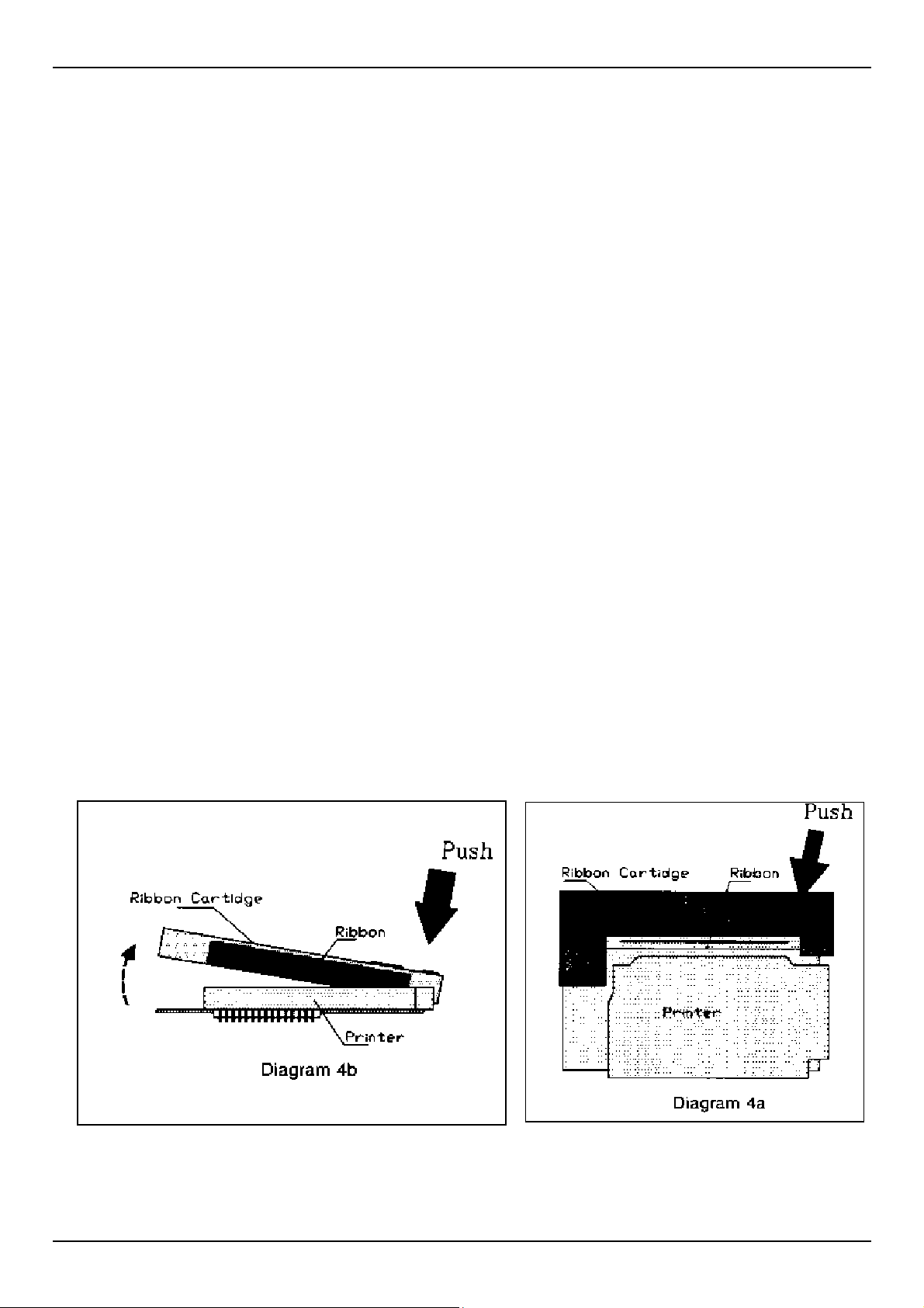
9. CHANGING PRINTER RIBBON
1. It is recommended that a new printer ribbon be fitted for every three paper rolls
consumed.
2. Remove the printer cover plate by following steps 1-3 for changing the paper roll.
3. Gently push down on the right hand side of the printer ribbon (the word PUSH is
embossed on the ribbon cartridge. The left side will flip up and the ribbon may be
removed from the printer.
4. Replace the ribbon in the same orientation; with the ribbon facing towards the
keypad and the word “PUSH” and “EJECT” on the right hand side. Locate the left
hand side of the ribbon cartridge in position first; with the ribbon fitting between
the metal plate and paper feed guide.
5. Wind up any slack in the paper roll, replace the printer cover plate fitted with the
new paper roll and press the hold-down buttons home. Note: The buttons must be
correctly aligned before they will click home.
6. Press “Off” when complete.
AutoStop Maxi User Manual Version 8.18 Page 14

10. WARRANTY
AutoTest Products Pty Ltd or any Authorised AutoTest Service Center warrants this
product against defects in material and workmanship for a period of 12 months from
the original date of purchase. This warranty applies only to products and
components supplied by AutoTest Products which can be identified by the trade
name or logo affixed to them or by other documents. AutoTest Products does not
warrant any products not supplied by AutoTest Products.
Note: The use of proper paper is very important to the operation of the printer. Use
of non standard paper will jam the printer and/or wear the print head. Use of nonstandard paper will void the warranty. Paper and printer ribbon cartridge are
available from AutoTest Products.
During the warranty period, AutoTest Products or any Authorised Service Center will
repair (or at its option replace) any defective component(s) without charge for parts
or labor, provided the product is freight prepaid to an authorised AutoTest Service
Center. Transit insurance and return freight will be at the owner’s expense.
In order to obtain calibration, warranty or non-warranty service, ship the product,
freight and insurance prepaid to your nearest AutoTest Service Center. Attach to the
product your name, address, contact phone numbers, description of the problem
and if a warranty claim, proof of purchase (dated sales receipt or invoice).
AutoTest Products or any Authorised AutoTest Service Center reserves the right to
refuse warranty repair if accident, abuse, misuse or misapplication has damaged
the product. In transit or as a result of service or modification by other than an
Authorised Service Center, nor are any other warranties expressed or implied,
including any regarding merchantability or fitness for any other particular purpose.
AutoTest Products or any Authorised Service Center is not responsible for incidental
or consequential damages resulting from the breach of any express or implied
warranty, including damage to property and, to the extent permitted by law,
damages for personal injury.
AutoStop Maxi User Manual Version 8.18 Page 15

11. QUICK GUIDE
After Unpacking
Charge the battery for 10 hours before initial use. The battery charger input is located to the right
of the printer. With proper care and use, the battery should last between two and five years. It is
recommended to recharge the battery nightly if the AutoStop Brake Tester is used regularly. Only
an approved battery charger with the correct voltage, waveform and terminal polarity should be
used. The battery must never be allowed to fully discharge as it will void the warranty.
Set-Up & Testing
1. Secure AutoStop Maxi in vehicle and attach pedal sensor to
brake pedal. This will vary from vehicle to vehicle; a mounting
bracket or straps may be used.
2. Press “ON”.
3. Enter Examiner ID and press “Yes”.
4. Remove pressure from pedal sensor. Processor measures
zero level of the pedal sensor.
5. Press “Yes” again.
6. Mistakes may be corrected by using the “<” or backspace key.
7. At the “Ready>” prompt, press “R” to run test. Enter the
vehicle registration number (or VIN number) and press “Yes”.
8. Srvc/Emrg? S/E. Select Service (S) or Emergency (E) test.
9. Ensure it is safe to run the test.
10.Before starting or repeating the test, remove foot from pedal sensor and brake pedal.
11.Press “S” to start (or “A” to abort).
12.Accelerate to speed and stop when safe.
13.Press “Y” to save or “N” to not save the results (if Brake Tester has data logging option).
14.Press “Y” to print or “N” to skip printing a duplicate.
15.Press “Y” to repeat test, “N” to end test.
16.Press “OFF”.
Change Paper
1. Remove printer cover from panel.
2. Remove paper roll spindle from cradle.
3. Load new roll (see ‘Paper Specifications’ regarding special
paper).
4. Press “ON”.
5. Enter Examiner ID and press “Yes”.
6. Press “P” to feed paper through printer.
7. Press any key to halt paper feed
8.
Replace paper roll assembly and printer cover.
9. Press “OFF”.
AutoStop Maxi User Manual Version 8.18 Page 16

NOTES:
AutoStop Maxi User Manual Version 8.18 Page 17

AutoStop Maxi User Manual Version 8.18 Page 18

AUTOTEST Products Pty Ltd
279 Normanby Road, Port Melbourne. VIC 3207 Australia
Phone: (+61 3) 9647 9797 Sales:(+61 3) 9647 9707
Service:(+61 3) 9647 9706 Fax: (+61 3) 9646 3427
Email:
info@autotest.net.au www.autotest.net.au
service@autotest.net.au sales@autotest.net.au
 Loading...