

Page 1
User Manual
Version 3.01
AUTOSTOP™ Suspension Meter
Page 2

E7474
DECLARATION OF CONFORMITY
We, AutoTest products Pty Ltd. declare under our sole responsibility that the product
AUTOSTOP™ Suspension Meter is in conformity with the provisions of the following Council
Directive: 1999/5/EC.
A copy of the Declaration of Conformity is available from http://www.autotest.net.au
© AutoTest Products Pty Ltd (AutoTest) [2019].
Copyright of the drawings, information and data recorded in this document (the information) is the
property of AutoTest Products. This document and the information are solely for the use of the
authorised recipient and this document may not be used, copied, or reproduced in whole or part
for any purpose other than that for which it was intended by Auto Test Products. Auto Test
Products makes no representation, undertakes no duty, and accepts no responsibility to any third
party who may use or rely upon this document or the information.
Under no circumstances shall Auto Test Products be responsible for any loss of data or income
or any special, incidental, consequential or indirect damages howsoever caused.
The contents of this document are provided "as is". Except as required by applicable law, no
warranties of any kind, either express or implied, including, but not limited to, the implied
warranties of merchantability and fitness for a particular purpose, are made in relation to the
accuracy, reliability of contents of this document. Auto Test Products reserves the right to revise
this document or withdraw it at any time without prior notice.
10242
Page 3

Table of Contents
AUTOSTOPTM Suspension Meter
1 UNPACKING AND FIRST TIME USE ........................................................................................................... 1
1.1 Battery Charging ............................................................................................................................................ 1
1.2 Self Test and Battery Check ....................................................................................................................... 1
2 FOR YOUR SAFETY ......................................................................................................................................... 2
3 OPERATION ..................................................................................................................................................... 3
3.1 Set-Up on Vehicle ........................................................................................................................................... 3
3.2 Running the Test ............................................................................................................................................ 3
3.3 Test Instructions Summary ....................................................................................................................... 7
3.4 Display Last Test Result .............................................................................................................................. 8
3.5 Printing Last Test .......................................................................................................................................... 9
3.6 Using Reference Method ............................................................................................................................. 9
3.7 Changing Test Parameters ...................................................................................................................... 10
3.8 Menu Reference .......................................................................................................................................... 11
4 UPLOADING TEST DATA ........................................................................................................................... 12
4.1 Installing the Data Logger Software .................................................................................................... 13
4.2 Uploading Tests using the Data Logger Software ........................................................................... 13
4.2.1 Downloading via Bluetooth ............................................................................................................... 17
4.3 Using the Data Logger software ............................................................................................................ 22
5 TROUBLESHOOTING .................................................................................................................................. 24
6 WARRANTY ................................................................................................................................................... 25
7 AUTHORISED SERVICE AGENTS: ........................................................................................................... 26
Page 4

AUTOSTOP™ Suspension Meter - User Manual v3.01 Page 1
1 UNPACKING AND FIRST TIME USE
Congratulations on your choice of an AUTOSTOP™ Suspension Meter. Please take the time to
read this User’s Manual before using the AUTOSTOP™ Suspension Meter in the field.
Incorrect or inappropriate use of this instrument may void the warranty.
Please complete the warranty registration card and post it to AutoTest Products Pty Ltd,
alternatively visit our website www.autotest.net.au and complete your warranty registration
on line. Your warranty registration ensures that you are kept up-to-date on any software or
hardware changes to your AUTOSTOP™ Suspension Meter.
The packing box of your AUTOSTOP™ Suspension Meter should contain the following:
1. AUTOSTOP™ Suspension Meter
2. User Manual
3. Warranty Registration Card
4. Calibration Certificate
5. Power Adaptor
6. Suspension Meter Data logger software CD-ROM
7. Data Download USB Cable
Optional Accessories:
• Bluetooth printer
AUTOSTOP™ Suspension Meter determines the vertical suspension movement, measuring
damping coefficient and counting number of rebounds. AUTOSTOP™ Suspension Meter has a
twelve-button operation via a tactile membrane keypad with LCD display. It is lightweight
(500grms) and compact (200x90x30mm) and can be installed on the body of the vehicle
near the wheel that is to be tested.
1.1 Battery Charging
When you receive your new Meter, you should charge the device to full. The device can be
easily charged by connecting the provided Power Adaptor.
1.2 Self Test and Battery Check
The self-test function is activated each time the AUTOSTOP™ Suspension Meter is powered,
it checks the clock, the battery level and other hardware checks. If the battery does not have
sufficient charge to be used, then it will display “Warning: Battery Low”.
Page 5

AUTOSTOP™ Suspension Meter - User Manual v3.01 Page 2
2 FOR YOUR SAFETY
Read these simple guidelines. Not following them may be dangerous. Read the complete
user guide. Further detailed information is given in this manual.
SWITCH ON SAFELY
Do not switch the device on when wireless device use is prohibited or when it may
cause interference or danger.
INTERFERENCE
All wireless devices may be susceptible to interference, which could affect
performance.
SWITCH OFF WHEN REFUELING
Do not use the device at a refuelling point. Do not use near fuel or chemicals.
SWITCH OFF NEAR BLASTING
Follow any restrictions. Do not use the device where blasting is in progress.
USE SENSIBLY
Use only in the positions as explained in the product documentation.
QUALIFIED SERVICE
Only qualified personnel may install or repair this product.
ACCESSORIES AND BATTERIES
Use only approved accessories and batteries. Do not connect incompatible products.
WATER-RESISTANCE
Your device is not water-resistant. Keep it dry.
CONNECTING TO OTHER DEVICES
When connecting to any other device, read its user's guide for detailed safety
instructions. Do not connect incompatible products.
Page 6
AUTOSTOP™ Suspension Meter - User Manual v3.01 Page 3
3 OPERATION
3.1 Set-Up on Vehicle
The vehicle must be stationary (at a complete stop) prior to commencement of the test.
Mount the Suspension Meter to the body of the vehicle, placing it near the wheel that is to be
tested. The device uses rubber suction cups that grip onto the body of the vehicle. Please
note that dirt particles on suction cups might damage body paint as well as can result in
loose grip, which can result in device falling down on ground.
The AUTOSTOP™ Suspension Meter is self-aligning by identifying its orientation at the
beginning of each test. The suspension meter can be installed at any angle facing any
orientation, but must be well secured for the entire duration of the test as movement can
cause erroneous readings. Before commencing the test, give the vehicle a firm shake to bring
shock absorbers at their natural position.
3.2 Running the Test
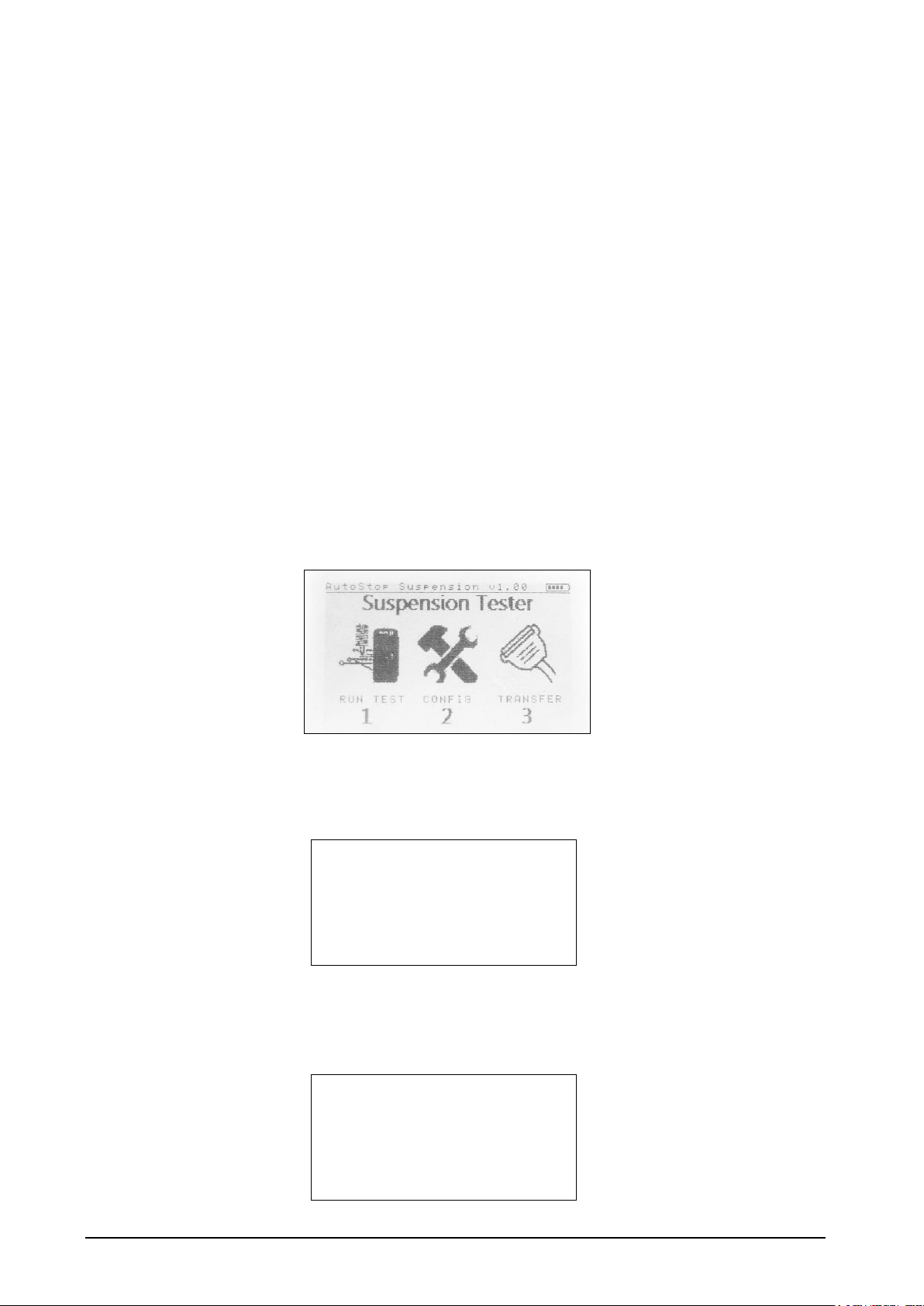
Turn on AUTOSTOP™ Suspension Meter by pressing the ON/OFF button if the device is
currently off. The Suspension Meter will go through a start-up procedure and will eventually
display Main Menu (a menu of three icons):
Before starting a test, make sure the device has sufficient (over 30%) battery life. To run a
suspension test, select “RUN TEST” by pressing ‘1’ from the keypad. The device will show
the following list of options on the screen:
1. Run New Test
2. Show Last Test
3. Print Last Test
4. Delete all Tests
5. Memory Usage
6. Return to Main Menu
Now select 1. Run New Test by pressing 1 once again. The device will ask the user to
confirm if the shock absorbers are warmed up or if the vehicle has been in motion for at
least 5 minutes during the last 30 minutes. Running a suspension test on a cold vehicle may
lead to erroneous result.
Has the vehicle been in
motion for at least 5 min
within the last 30 min?
1. Yes
2. No
Page 7

AUTOSTOP™ Suspension Meter - User Manual v3.01 Page 4
After the warm up confirmation, the device will prompt for Test Mode.
Select Test Mode?
1. By Driving
If you are selecting option 1. By Driving, please make sure you drive the vehicle forward
and suddenly apply foot bake for testing the front two wheels. For testing the rear two
wheels, please make sure you reverse the vehicle and suddenly apply hand brake. Please be
mindful of other people around while driving the vehicle.
After selecting the Test Mode, the device will prompt for Examiner ID (Operator Name).
Use the device’s keypad to type in the name of the person performing the test. The DEL key
behaves like the Backspace key in a PC keyboard and it can be used to erase the last
character in the input field.
Enter Examiner ID:
After entering the Examiner ID, press ENTER to continue. Now the device will prompt for
Vehicle Registration, type in the registration number of the vehicle that is to be tested.
Again, use the keypad to erase and type in the vehicle’s registration number.
Enter Vehicle
Registration:
After entering the Vehicle Registration Number, press ENTER to continue. If the registration
number you just entered has any wheel that was recently tested, the device will
automatically load the Customer Name from the database. Otherwise, for a new vehicle’s
entry, the device will prompt for Customer Name. Enter Customer’s name using the keypad
and press ENTER.
Enter Customer Name:
If reference method was used in the device configuration (see Section 3.6), the following
dialogue will be displayed:
Vehicle Chassis Type
1. Soft (Comfortable)
Page 8

AUTOSTOP™ Suspension Meter - User Manual v3.01 Page 5
2. Normal
3. Hard (Sporty)
4. Manuf. Defined
5. Unknown
If the vehicle being inspected has a chassis system that was designed to be soft or
comfortable, select option 1. For normal vehicles such as an average European vehicle, use
option 2. If the chassis system is designed be hard or has characteristics of a sports car, use
option 3. If the reference damping factor for a particular vehicle is known, user can select
option 4 (Manufacturer Defined) to specify reference damping data for that vehicle (see
Section 3.6). If the user is unsure about the chassis type, select option 5. By selecting option
‘5. Unknown’, reference method will not be used.
The device will now prompt for wheel selection. Select the wheel that you are currently
testing by pressing numbers from 1 to 4 using the keypad. Press 5 to cancel the test and
return to the RUN TEST menu.
If the vehicle registration number you just typed in has any wheel that was recently tested,
the device will not show those wheels that are already tested, instead it will only show
wheels that are yet to be tested. If you want to overwrite a test for a particular wheel that is
already tested, then select 6. List all wheels* and then select the wheel that you want to test
again.
1. Front Left
2. Front Right
3. Rear Right
4. Rear Left
5. Cancel Test
6. List all wheels*
* Option #6 will only be displayed if at least one of the wheels is not displayed.
Wheels that are not displayed in the list are those that have already been tested and stored.
After selecting the wheel that is being tested, the device will prompt for a ready trigger
Press any key when ready or press DEL to abort test. Hit ENTER from the keypad when
you are ready to run the suspension test.
Note: Before running a test on a wheel, give a shake to the wheel by bouncing the vehicle down
a few times.
Running a push-down test
Push down test can be conducted in two ways:
1. Single Push Method
2. Multiple Push Method (recommended)
1. Single Push Method
In single push method, push the vehicle a hard push and immediately release it, letting the
vehicle bounce up at its natural rate. If the push-down force was large enough for the
suspension meter to sense the trigger, the suspension meter will immediately start
sampling/recording the vehicle oscillation. After over 1.5 sec, the sampling will end and
suspension meter will process the result.
Page 9
AUTOSTOP™ Suspension Meter - User Manual v3.01 Page 6
If the vehicle was not pushed hard enough, or the suspension meter finds some problem
with obtained result, the device will display the following error message:
Abnormal results
obtained!
1. Run test again
2. Abort Test
Select 1. Run test again to redo the test with harder push down force.
2. Multiple Push Method
Multiple Push down method is similar to the single push down test, except the vehicle is
pushed down a number of times to excite the suspension system before pushing a final hard
push. When running a multiple push down test, be careful not to obstruct the upward
bounce of the vehicle. Only push the vehicle down when the vehicle is bounced back to its
top height and then release. Take extra care when making the last push. The last push should
have the maximum force compared with the previous pushes.
Note: Do not obstruct the upward motion of the vehicle.
For better consistency, multiple push down method is recommended.
Results will be displayed on the screen after each test. The meter will ask user whether the
result should be saved. The user can save the test and continue to the next wheel, or user can
redo the test for the selected wheel.
** Suspension rating is evaluated based on Damping ratio., number-of-rebounds, and reference
method used (see section 3.6 & 3.7 for more information).
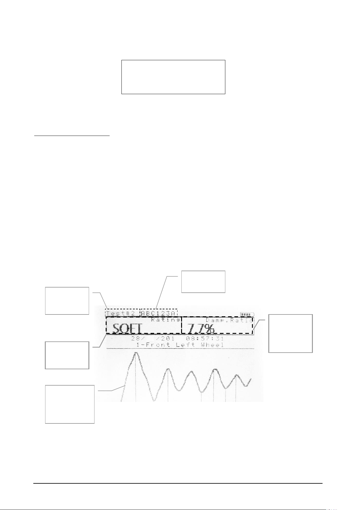
The graph will remain on the screen until the user presses any key from the keypad. Once a
key is pressed, the device will display the following menu:
Current Test
file no.
(record no)
Vehicle Reg.
No.
Suspension
Rating **
Damping
Ratio of the
vehicle’s
suspension
Plot of
vehicle’s
vertical
oscillation
Page 10

AUTOSTOP™ Suspension Meter - User Manual v3.01 Page 7
1. Save test
2. Don’t save
3. Redo Test
Press 1 to save the results obtained for the current wheel. Press 2 to discard and erase
results and return to the RUN TEST Menu. In case of odd results, press 3 to redo the test.
3.3 Test Instructions Summary
Screen Display
Instruction
Keys to Press
Blank Screen
Switch On
ON/OFF
Initial splash screen
Press any key to skip
Open Test Menu
Press 1 from the keypad
Examiner ID:
Enter Examiner ID or Operator’s
name
Use keypad to type Examiner ID.
When done, Press ENTER.
Enter Vehicle Registration:
Enter the Registration no
Use keypad to type Vehicle
Registration No. and press
ENTER
Enter Customer Name:
Enter Customer Name
Use keypad to type Customer
Name and press ENTER
Selection Chassis type
(only if reference method is
used)
Select vehicle chassis type.
Press a key from ‘1’ to ‘5’ to
select an option
Wheel to test:
Select a wheel to run test.
Press a key from ‘1’ to ‘4’ to
select a wheel
Press any key when ready or
press DEL to abort test
Press any key to commence the
test or DEL to cancel test and
return to Test Menu
Press any key to commence the
test
Waiting for a trigger…
Push down the vehicle (or drive)
Sampling…
Wait for the result
Processing…
Wait for the result
Graph Screen
Displays results from the
currently conducted suspension
test
Press ENTER
1. Save Test?
To save test result
Press 1 to save
2. Don’t Save?
To discard results and abort test
Press 2 to abort test and results
3. Redo Test?
To Redo the test
Press 3 to repeat the test
Page 11

AUTOSTOP™ Suspension Meter - User Manual v3.01 Page 8
Must:
– Fix Suspension Meter securely
– Install in a stationary vehicle
– Place it close to the wheel that is being tested
– Shake (push down) the vehicle before starting the actual test
– For driving test,
o For front wheels: must drive the vehicle forward and use foot brake
o For rear wheels: must drive the vehicle backward and use hand brake
Must not:
– Pull up the vehicle (let the vehicle bounce up naturally)
3.4 Display Last Test Result
After running a successful suspension test on a vehicle, the results for that vehicle can be
retrieved and a summary of all four wheels can be displayed on the suspension meter’s
screen. To view the results for all four wheels of the last tested vehicle, select RUN TEST
from the Main Menu by pressing 1. The device will then display the Test Menu. Select [2.
Show Last Test] from the Test Menu.
Test#2 ABC123A
Test Date: 18/01/2011
1-Front Left
SOFT
15:05
2-Front Right
GOOD
15:04
4-Rear Left
N/A
3-Rear Right
HARD
15:08
The above screen displays a brief summary of all four wheels of the latest vehicle that is
tested. In the above summary screen, the displayed ‘N/A’ for the 4th wheel (Read Left)
indicates that ‘Not available’, or no test was conducted or stored for that wheel.
Press a key from ‘1’ to ‘4’ to view the results for an individual wheel. Alternatively, press
ENTER to sequentially view results for all wheels. Keep pressing the ENTER key to switch to
the next screen. At the end of each cycle, the device will prompt “Print Results?”. Results can
be printed out using an optional Bluetooth printer. For more information regarding the
printing process, see Section 3.5. To return to the Test Menu screen, select ‘3. Return’ once
the print dialogue appears on the screen. Alternatively, by pressing any key from ‘5’-‘9’ and
‘0’ during an individual result screen will return to the Test Menu.
Test Number
(Record no)
Vehicle Reg. No.
Wheel
Suspension
Rating
Test Time
Page 12

AUTOSTOP™ Suspension Meter - User Manual v3.01 Page 9
3.5 Printing Last Test
Results for all four wheels for the latest tested vehicle can be printed out on a paper slip
using an optional Bluetooth printer.
In order to print the latest test results using a Bluetooth printer, first switch on the printer
and then place the device close to the Bluetooth printer.
Aligning the infrared port on Suspension Meter and the Bluetooth printer
Turn on the suspension meter if it’s switched off. From the Main Menu containing three
icons appears, select ‘RUN TEST’ by pressing 1 from the keypad. When the Test Menu
appears, select ‘3. Print Last Test’. The device will display “Printing Test #n”, where n is
the test number for the latest test.
Note: In case if the Bluetooth printer fails to print, please check the printer battery level.
3.6 Using Reference Method
Reference method allows results to be generated in reference to the original factory
performance of the shock absorbers. Since different vehicles have different factory ratings
for shock absorbers, it is impractical to have the factory-rating list for the shock absorbers of
all kinds of vehicles and models. Instead, the device groups all vehicles into three categories
and assigns reference data to each category:
Category
(Chassis type)
Standard Reference Data
Front Axle
Rear Axle
Soft (comfortable)
60
60
Normal
70
70
Hard (Sporty)
80
80
The default reference data listed in the above table can be modified in the suspension meter
to adopt the local regulations.
The reference method can be turned off from the configuration menu. To change the
reference data, or turn off reference method, see Section 3.8.
Page 13

AUTOSTOP™ Suspension Meter - User Manual v3.01 Page 10
3.7 Changing Test Parameters
AUTOSTOP™ Suspension Meter uses two ways to determine the performance of a shock
absorber. The first method uses Damping Ratio factor and the second method looks at the
number of rebounds of the suspension system. The device can be configured to use both
methods; thereby, the performance of the suspension system using the Damping Ratio
method and the Rebound methods is averaged.
The default calculation method for determining the performance of the suspension system is
using both ‘Damping Ratio’ and ‘Rebound’ methods. Users can change the calculation
method by taking the following steps:
• From the Main Menu, select ‘CONFIG’ by pressing 2 from the device keypad.
• Select 3. Result calculation by pressing 3
• Select 1. Calculation Method by pressing 1
• To use the Damping Ratio method only, select ‘1. Using Damping Ratio’
• To use the Rebound method only, select ‘2. Using Rebounds’
• To use both the Damping Ratio method and the Rebound method, select ‘3. Using Both’
• To return, select ‘4. Return’
To quantize and describe the performance of the vehicular suspension system, AUTOSTOP™
Suspension Meter uses a range table for each calculation method. The following table
contains default values or parameters for each method that are used to rate or describe the
performance of the vehicular suspension system.
Rating
Damping Ratio
(zeta, ζ)
Rebound Method
(No. of bounces)
POOR
0 ≤ ζ < 10%
Rebounds > 4
SOFT
10 ≤ ζ < 15%
3 ≤ Rebounds < 4
GOOD
15 ≤ ζ < 35%
2 ≤ Rebounds < 3
HARD
35 ≤ ζ < 100%
Rebounds ≤ 1
Users can change these parameter ranges by taking the following steps:
• From the Main Menu, select ‘CONFIG’ by pressing 2 from the device keypad.
• Select 3. Result calculation by pressing 3
• Select 2. Parameter Range by pressing 2
• To change the parameter values for the Damping Ratio method, select ‘1. Set Damping Ratio
Range’
• Or, to change parameter value for the Rebound method, select ‘2. Set Rebounds Range’
• Select the Rating for which you want to update the parameter range using keypad (1-4).
• When an input dialogue box appears, enter the new value and press ENTER.
Users can always revert back to the default parameters, in case of invalid range entries,
using the following steps:
• From the Main Menu, select ‘CONFIG’ by pressing 2 from the device keypad.
• Select 3. Result calculation by pressing 3
• Select 3. Reset Parameters by pressing 3
Page 14

AUTOSTOP™ Suspension Meter - User Manual v3.01 Page 11
3.8 Menu Reference
Section
Sub Menu
Sub Menu 2
Description
Keys to
Press
MAIN MENU
RUN TEST
Suspension Test Menu. Contains all
options related to running and
viewing suspension tests
Press 1
1. Run New Test
Starts a new suspension test
Press 1
Warm
suspension
check
Prompts user to check if the vehicle
was in motion recently.
1-Yes
2-No
Examiner ID
Prompts for Examiner ID
Type then
press
ENTER
Vehicle Reg. No
Prompts for Vehicle Reg. No.
Type then
press
ENTER
Customer
Name
Prompts for Customer Name
Type then
press
ENTER
Chassis Type
Prompts for Vehicle Chassis Type
(only if reference method is used)
Press 1-4
Ready?
Prompts for Ready trigger
Press
ENTER
Graph Screen
Displays the current test’s result
Press
ENTER
Save?
Prompts for Save/Discard results
1-Save
2-Discard
3-Redo
2. Show Last Test
Displays the results for the latest
test.
Press 2
Summary Page
Display the summary of all four
wheels for the last tested vehicle
Press 1-4
or ENTER
Print Results?
Prompts user to print the current
(latest) results using optional IrDA
printer
1-Yes
2-No
3-Return
3. Print Last Test
Prints the latest results using
optional IrDA printer
Press 3
4. Delete all Tests
Warning! Clears the user memory
deleting all existing stored tests.
Users should upload data prior to
deleting all tests.
Press 4
Delete all
Tests?
Confirms if user really wants to
delete all stored tests.
1-Delete
2-Cancel
5. Memory Usage
Displays the number of stored tests.
Press 5
Memory Usage
page
Any key to
exit
6. Return to Main
Menu
Returns to the Main Menu
Press 6
CONFIG
Displays settings and result
calculation options
Press 2
1. Contrast
Adjusts the display brightness level
Press 1
2. Date/Time
Displays the current date and time
Press 2
Page 15

AUTOSTOP™ Suspension Meter - User Manual v3.01 Page 12
3. Result
Calculation
Allows result calculation parameter
adjustments
Press 3
1. Calculation
Method
Displays suspension rating
calculation methods
Press 1
1. Using Damping Ratio
2. Using Rebounds
3. Using Both
4. Return
Select 1-4
2. Reference
Method
Enables or disables reference
method.
Press 2
1. Enable Reference
Press 1
2. Disable Reference
Press 2
3. Return
Press 3
3. Parameter
Range
Allows suspension rating parameter
alteration
Press 3
1. Set Damping Ratio Range
Press 1
2. Set Rebounds Range
Press 2
3. Reference Damping
Press 3
4. Return
Press 4
4. Reset
Parameters
Resets Parameter Range values.
Also sets “1. Calculation Method” to
“3. Using Both” (i.e. using Damping
ratio and Rebounds method)
Press 4
5. Return
Return to the CONFIG menu
Press 5
4. Device Info
Displays device information such as
version, serial number, battery level,
date and time.
Press 4
Device
Information
Page
Press any
key to exit
5. Printer
Displays printing options
Press 5
1. Print
Graphs
Enables printing of graphs of
suspension tests.
Press 1
2. Disable
Graphs
Disables printing of graphs. This
option can be used to save printer
roll.
Press 2
3. Return
Return to the CONFIG menu
Press 3
6. Return to Main
Menu
Returns to the Main Menu
TRANSFER
This menu option allows device to
upload suspension test results and
to update firmware to a connected
PC. The device must be connected to
the PC using the optional serial
cable.
Press 3
4 UPLOADING TEST DATA
The AUTOSTOP™ Suspension Meter has a upload facility that allows users to transfer test
results from the unit onto a PC via a custom Serial Cable (optional accessory) for analysis
and printing. The Suspension Meter can hold up to 100 tests numbered one to a hundred. To
upload all tests stored in the suspension meter, AUTOSTOP™ Suspension Meter Datalogger
software must be installed and running on the PC.
Page 16
AUTOSTOP™ Suspension Meter - User Manual v3.01 Page 13
4.1 Installing the Data Logger Software
Before installing the AUTOSTOP™ Suspension Meter Datalogger software, make sure your
computer meets the minimum system requirements:
• Microsoft Windows XP or greater
• One unused USB port
• At least 50 MB of hard disk space
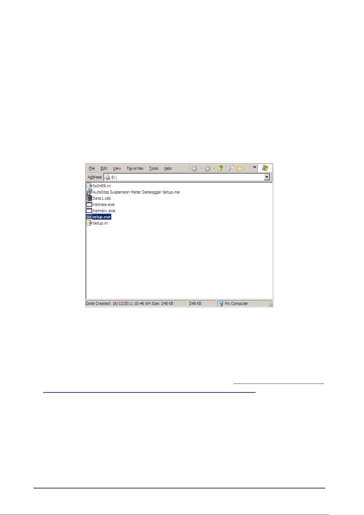
To install the data logger software from CD, please follow the following steps:
1. Insert the Suspension Test Data Logger Software CD-Rom installation disk into
your disk drive.
2. If the Data Logger software setup does not run automatically, then open your CD-
ROM drive in Windows Explorer
3. Select and run file “setup.exe”
4. Follow Setup prompts.
Note: If you already have a copy of an older version of suspension meter software installed,
you may have to uninstall it first.
The latest version of the data logger software for AUTOSTOP™ Suspension Meter can be
obtained from the Internet by going to the AutoTest website: http://www.autotest.net.au/
or http://www.autotest.net.au/products/autostop-suspension-meter/
4.2 Uploading Tests using the Data Logger Software
After successfully installing the data logger software, run the Data Logger software from the
desktop or from the start menu, and perform the following steps:
Step 1: Use the supplied USB cable and connect one of the cable to the meter and the other
end to your PC. Turn ON the suspension meter.
Page 17
AUTOSTOP™ Suspension Meter - User Manual v3.01 Page 14
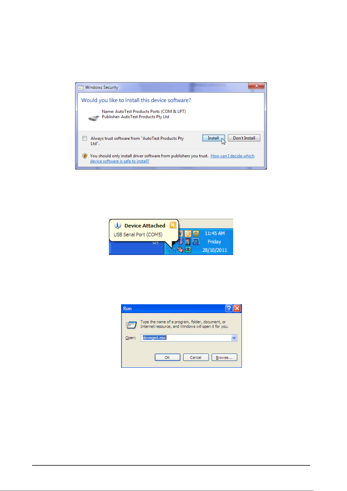
When the suspension meter is first connected, Windows will try to install drivers for it.
Please wait until Windows has finished installing drivers. You might see the following
message box during the installation of the USB drivers. Please select Install to install the USB
drivers.
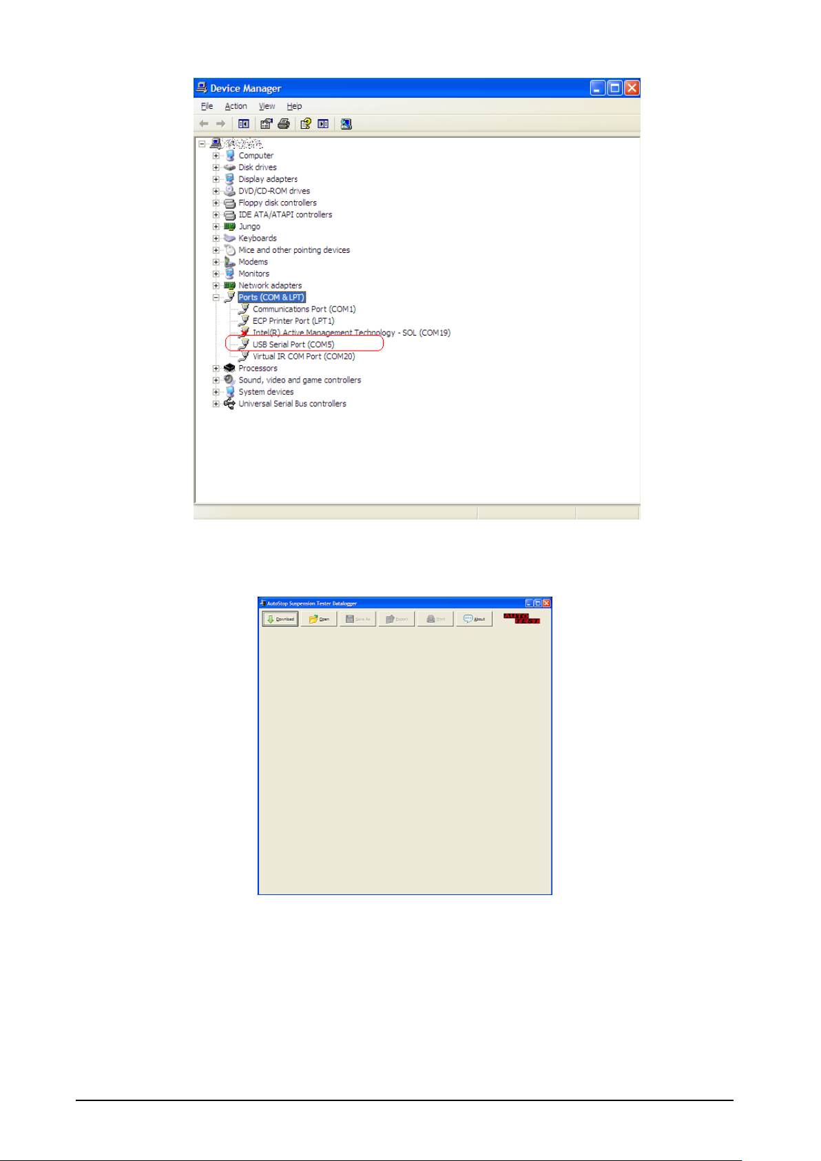
Step 2: Once the drivers have been installed, you may see the following pop-up screen near
the system clock. The message box will display the COM port to which the suspension meter
is connected. You need to know this COM port number (for example COM5 in the following
image) when communicating and downloading data from the suspension meter.
Alternatively, if you did not see the above ‘Device attached’ pop-up screen, you can check the
COM port number by taking the following steps:
• Open ‘Device Manger’ by going to Start -> Run -> Type ‘devmgmt.msc’ and click OK.
• Then in the Device Manger window, open Ports (COM & LPT) node and find ‘USB
Serial Port’ in the list. Note the COM port number appended next to ‘USB Serial
Port’.
Page 18
AUTOSTOP™ Suspension Meter - User Manual v3.01 Page 15
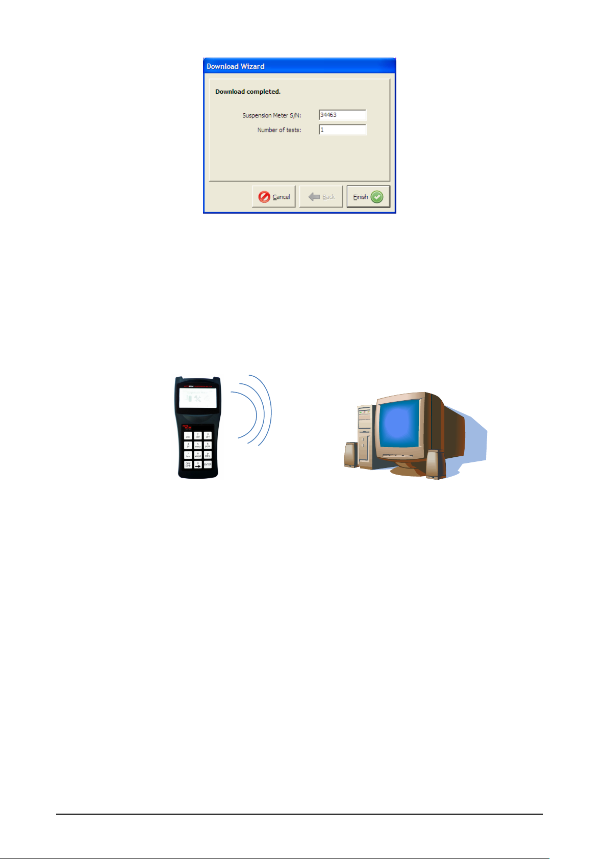
Step 3: Open the Suspension Meter Data logger window and click on DOWNLOAD. A
Download Wizard window will appear. Follow the download prompts.
Step 4: Select the right COM port to which the suspension meter is connected. The software
will display a list of detected COM ports. Select the appropriate COM port and click on NEXT.
Page 19

AUTOSTOP™ Suspension Meter - User Manual v3.01 Page 16
Note: For ordinary RS232 cable connection, it is very likely that the COM port would be
COM1 or COM2. If you are using a USB cable, you need to select the COM port you would
have figured out in STEP 2.
Step 5: When you see the above screen on your PC, switch ON the Suspension Meter. When
the Main Menu appears, select ‘TRANSFER’ by pressing 3 from the keypad on the device.
Download will automatically commence once the connection is successfully established.
Step 6: The Download Wizard window will display the download progress. Wait until the
download finishes.
Step 7: After test data has been downloaded a small window will appear that says
‘Download completed’. Click on FINISH to view the downloaded tests.
Page 20
AUTOSTOP™ Suspension Meter - User Manual v3.01 Page 17
4.2.1 Downloading via Bluetooth
Before connecting the suspension meter to the PC using the Bluetooth interface, make sure
the PC supports Bluetooth connectivity.
Once the Data Logger software has been installed, run the software on the PC and switch ON
the suspension meter by pressing the ON/OFF key.
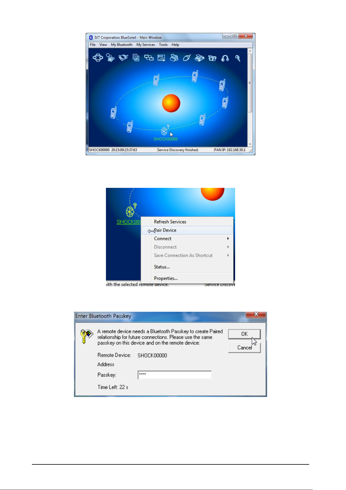
When connecting the Suspension Meter for the first time using the Bluetooth interface, user
will need to configure the Bluetooth connection. To configure the Bluetooth connection,
open your Bluetooth manager program on your PC and search for Shock##### device,
where '#####' is the serial number of the suspension meter.
Note: the screenshots provided below many not be the same on your PC.
For information regarding Bluetooth device pairing on your PC, please refer to the
documentation of your Bluetooth Manager.
Bluetooth
Page 21
AUTOSTOP™ Suspension Meter - User Manual v3.01 Page 18
Select the device Shock##### from the list of discovered Bluetooth devices and create
pairing.
When prompted for the pairing code or pin number, enter “0000”.
Page 22

AUTOSTOP™ Suspension Meter - User Manual v3.01 Page 19
Once the pairing is established, refresh device services and connect using Bluetooth serial
port service.
If the following message appears, note down the serial port and press Yes. The serial port
will be later used by the datalogger software.
Page 23

AUTOSTOP™ Suspension Meter - User Manual v3.01 Page 20
Users can also check the COM port of the Bluetooth device by viewing the status of the
device.
Once the Bluetooth connection is setup, the user can now download test results from
AutoStop Suspension Meter using the Bluetooth interface. To download the results, open
AutoStop Suspension Meter Datalogger software and click on “Download” button.
Page 24
AUTOSTOP™ Suspension Meter - User Manual v3.01 Page 21
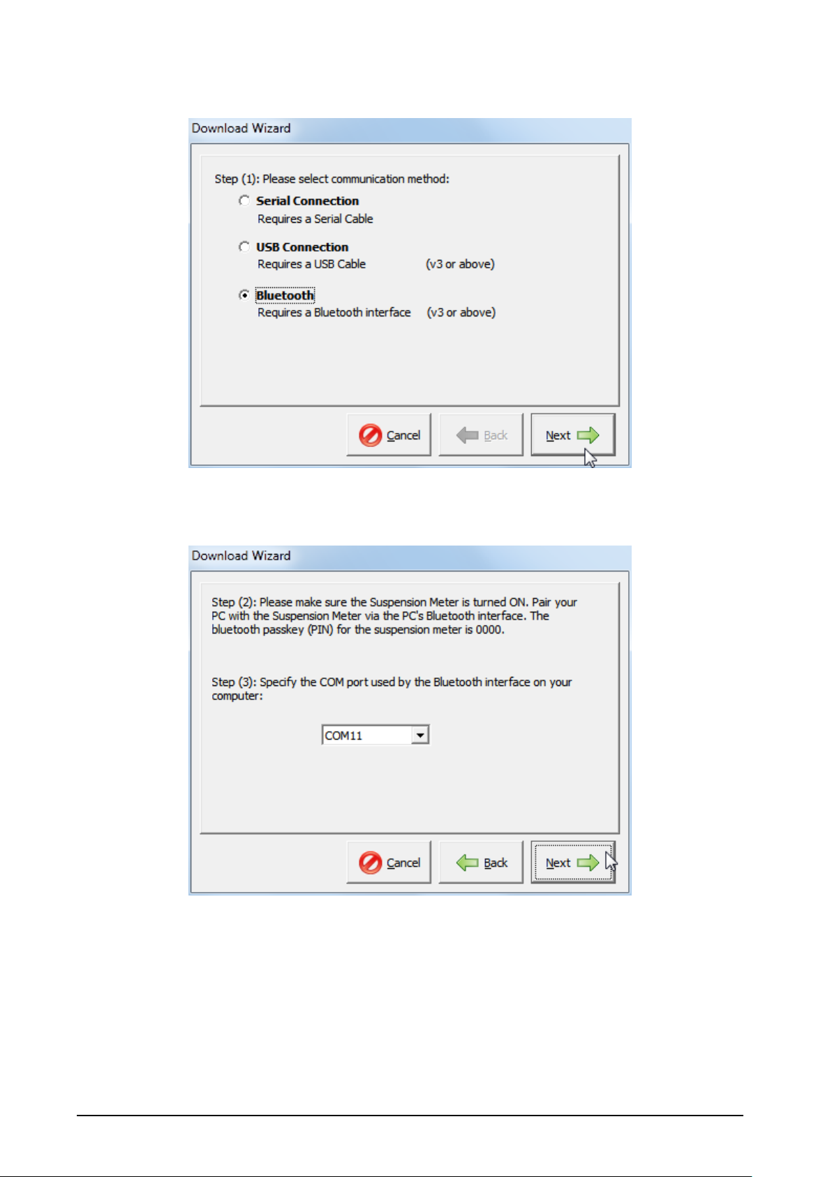
When the following connection window appears, select “Bluetooth” connection and press
Next.
Select the COM port number of the Bluetooth connection connected with the suspension
meter. The COM port number is the same COM port obtained during the Bluetooth pairing
process.
Make sure the suspension meter is ON. Press Next to continue. Once the connection is
established, the datalogger software will acquire a list of all tests currently stored on the
device.
Page 25

AUTOSTOP™ Suspension Meter - User Manual v3.01 Page 22
Select the tests that need to be downloaded and press Next. Datalogger software will then
download the selected tests.
Once the desired tests have been downloaded, press Finish to return to the main window
and view test results.
4.3 Using the Data Logger software
The Data logger will display all the saved tests and you can view the results of the particular
test and view corresponding graph for each test.
Page 26

AUTOSTOP™ Suspension Meter - User Manual v3.01 Page 23
There are options on the data logger such as:
1. Open: in order to open a saved file on your PC
2. Save: to save the results onto your PC
3. Export: this option can be used to view and save the test result in Microsoft Excel
compatible format.
4. HTML Report: displays the suspension test report for the selected vehicle in a text
format that can be selected and copied to another application such as Microsoft
Word.
5. Print: this option can be used to print the test result. There are options to print unit
details, test details and the data table.
List of all uploaded tests
Page 27

AUTOSTOP™ Suspension Meter - User Manual v3.01 Page 24
6. About: to view information about Data logger.
5 TROUBLESHOOTING
Problem
Potential Cause and Action Necessary
Suspension Meter will not turn on
Internal electronics have failed - return unit for
servicing.
Suspension Meter not recording
keypad input
Keypad damaged- return unit for servicing.
Suspension Meter turns itself off
during use
Battery flat-battery needs to be recharged.
Suspension Meter Displays
“Battery Flat”
Battery flat-battery needs to be recharged.
Suspension Meter displays Clock
failed
The in-built clock has failed. It might be an electronic
fault, or the unit needs to be recalibrated. Please return
unit for servicing & inspection.
Page 28

AUTOSTOP™ Suspension Meter - User Manual v3.01 Page 25
6 WARRANTY
AutoTest Products Pty Ltd or any Authorised AutoTest Service Centre warrants this product
against defects in material and workmanship for a period of 12 months from the original
date of purchase. This warranty applies only to products and components supplied by
AutoTest Products which can be identified by the trade name or logo affixed to them or by
other documents. AutoTest Products does not warrant any products not supplied by
AutoTest Products.
During the warranty period, AutoTest Products or any Authorised Service Centre will repair
(or at its option replace) any defective component(s) without charge for parts or labour,
provided the product is returned freight prepaid to an authorised AutoTest Service Centre.
Transit insurance and return freight will be at the owner’s expense.
In order to obtain calibration, warranty or non-warranty service, ship the product, freight
and insurance prepaid go to your nearest AutoTest Service Centre. Attach to the product
your name, address, contact phone numbers, description of the problem and if a warranty
claim, proof of purchase (dated sales receipt or invoice).
AutoTest Products or any Authorised AutoTest Service Centre reserves the right to refuse
warranty repair if accident, abuse, misuse or misapplication has damaged the product. In
transit or as a result of service or modification by other than an Authorised Service Centre,
nor are any other warranties expressed or implied, including any regarding merchantability
or fitness for any other particular purpose.
AutoTest Products or any Authorised Service Centre is not responsible for incidental or
consequential damages resulting from the breach of any express or implied warranty,
including damage to property and, to the extent permitted by law, damages for personal
injury.
Page 29

AUTOSTOP™ Suspension Meter - User Manual v3.01 Page 26
7 AUTHORISED SERVICE AGENTS:
AUSTRALIA
AutoTest Products
61-63 parsons St, Kensington, Victoria 3031
Australia. Phone: +61 3 88403016.
CHINA
Itach Autotech Corp
Room 703 Building A,Guo Run Commercial Plaza, No.46 West,. Feng Tai District, Beijing
100073
PH: (+10) 8365 9442
DENMARK
BM Autoteknik A/S
Erhvervsparken 7, 9632 Moldrup,
PH: (+ 45) 8669 2022
FRANCE
Actia Muller Services
Rue Des Tourneballets, Luce,
PH: (+332) 3733 3536
FRENCH POLYNESIA
Cogicat snc.
51 Rue Des Remparts Prolongee, B.P 2828, Papeete, TAHITI, 98 713
PH: (+ 6) 8942 8175
MACEDONIA
Velmar d.o.o.
Gjorce Petrov 10, 1000 Skopje, Makedonija.
PH: (+389) 2204 0288
MALAYSIA
Tritech Safety Sdn Bdn
No38, 2nd Floor, Jalan Pandan Indah, Kawasan Industri Ampang Tambahan, 68000
Ampang, Selangor D.E.
PH: (+603) 4291 0988
NEW ZEALAND
Brake & Transmission NZ
21-27 Omega St., Albany, Auckland
PH: (+ 64) 9414 3205
SOUTH AFRICA
Brakecore Supply Co
5 Oosthuise St, Ermelo, 2350.
PH: (+271) 7819 3412
Page 30

AUTOSTOP™ Suspension Meter - User Manual v3.01 Page 27
UNITED KINGDOM
Tecalemit Garage Equip. Co. Ltd
Unit 2,Eagle Road, Langage Bus Pk., Plympton, Plymoth, Devon, PL7 5JY
PH: (+017) 5221 9150
UNITED STATES OF AMERICA
Commercial Vehicle Consultants Inc.
144 Overlook Ave, Staten Island, NEW YORK, 10304.
PH: (+171) 8980 3651
Page 31

AUTO
TEST
Products Pty Ltd
61-63 Parsons St Kensington VIC 3031 Australia
Phone: (+61 3) 8840 3000 Sales:(+61 3) 8840 3017
Service: (+61 3) 8840 3016 Fax: (+61 3) 8840 3099
Email: service@autotest.net.au info@autotest.net.au
Email: sales@autotest.net.au www.autotest.net.au
 Loading...