

Page 1
AUTOTECH
Installation Instructions
PART NUMBER: 10.425.1426K
DESCRIPTION: ClubSport® Front Adjustable Swaybar, Mk3 VR6 Models
TOOLS REQUIRED: PARTS LIST:
Two Jackstands (1) Swaybar
Metric Wrenches, 13-19mm (2) Inner Polyurethane Bushings
Metric Sockets, 13-19mm (2) ARP 8mm 12pt. bolts
Large Screwdriver (4) 8mm Nyloc nuts
Pliers (2) 8mm washers
Bentley Manual Recommended
PROCEDURE:
1. Set the handbrake on your car and loosen, but do not remove the front wheel lug bolts.
2. Raise the front of the car, support it with jackstands under the factory “jack pads,” and
remove the front wheels.
3. Remove the bolt that holds the swaybar link rod to the A-arm on each side. The link rod
should still be attached to swaybar at this time.
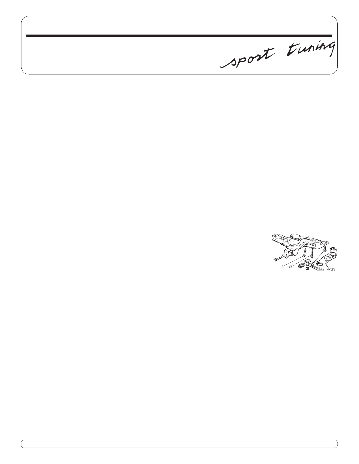
4. Remove the two rear-most subframe bolts (fi g. 1, bolts 2 and 3) from
the subframe on each side. Remove the 13mm bolt between subframe
bolts 2 and 3 (fi g. 1). This bolt holds the swaybar clip to the subframe.
Loosen the two front subframe bolts (fi g. 1, bolt 1) two turns in order
to loosen the subframe. Pull the rear of the subframe away from
the body and place a wedge (the large screwdriver’s handle) between
the two. Lift up the inner swaybar clamps and slide the swaybar out
towards the rear.
5. Note where the inner bushings are located on the factory bar. Spread some moly grease
in the same area on the Autotech swaybar. To facilitate installation of the of the inner
bushings, spray some WD-40 or other light oil on the bends of the swaybar leading up to
area with moly grease on it.
6. Note the proper position of the notch in the bushing. It should face up and to the rear.
Slide the inboard polyurethane bushings on the swaybar, bringing them down to the area
with the moly grease. Move bushing around to spread the grease throughout the bushing.
7. Remove the swaybar link rods from the factory swaybar and install them on the Autotech
swaybar (The supplied hex spacers are attached to swaybar before the the link rod for
the soft setting, for the stiff setting, don’t use the hex spacers.)
8. Place each end of the swaybar on top of the A-arms and swing the rear of the swaybar up
into the inboard brackets. Note: It is easier to “pre-hook” the inboard clips in their mounts
before the bar and its bushings are pressed into place.
9. With a pair of pliers, pull the inboard clip down over bushing until it touches the subframe.
While holding the clip in place, insert the bolt through the subframe and into the inboard
clip. Tighten the bolt to 18 ft lbs. Re-attach the link rods to the A-arms.
fi g. 1
Phone 949.240.4000 Fax 949.240.045032240-E Paseo Adelanto, San Juan Capistrano, CA 92675
Page 2
(cont)
10. Finally, re-attach the subframe to the body. Tighten bolts 1 and 2 (fi g. 1) to 52 ft lbs +1/4
turn (90 degrees). Tighten bolt 3 (fi g. 1) to 48 ft lbs.
11. Loosen and remove the rear ball-joint attachment bolt.
soft medium fi rm*
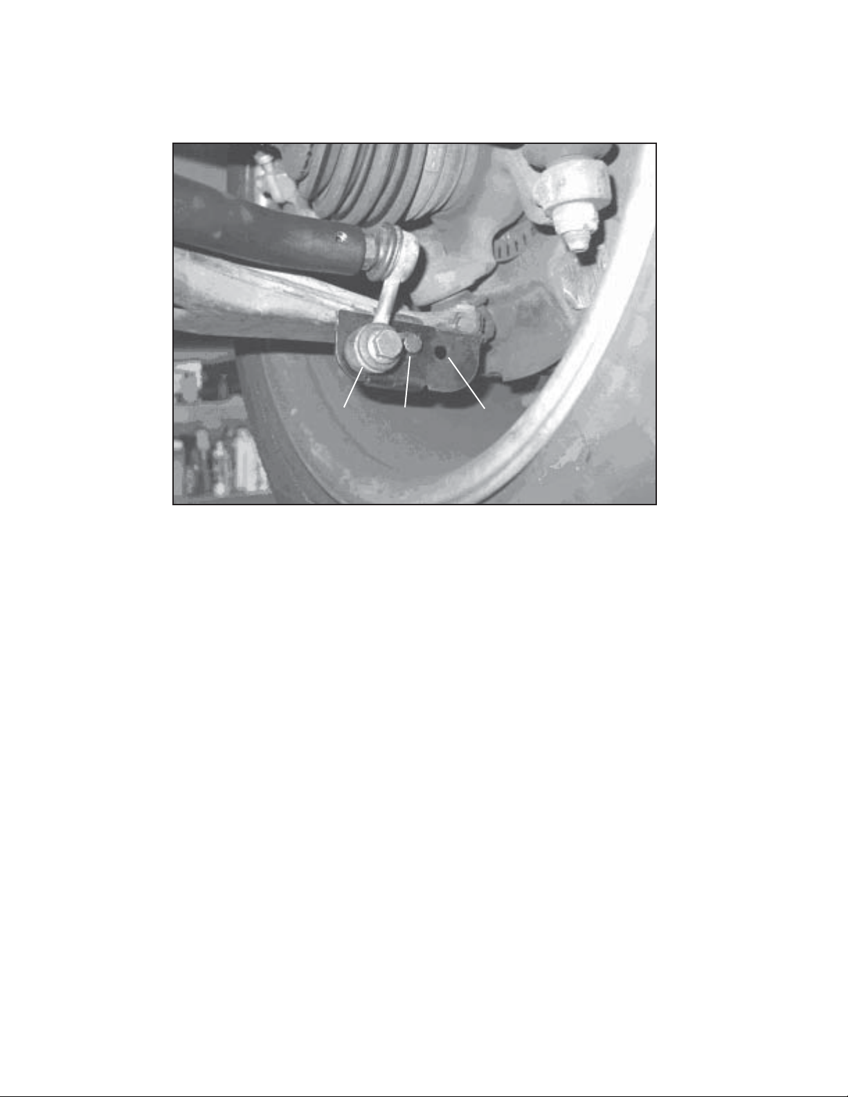
12. Attach the supplied bracket to the A-arm using the rear ball-joint attachment bolt and
the supplied hardware (the new bolt, washer, and nut are used in the original hole for the
end link.)
13. Attach the end link to the new bracket. The inside hole is the softest setting. For the
stiffest setting, use the outer hole.
* To use the outer hole, you must fi rst install the hex end-link spacer in the bar end. This
extends the reach of the swaybar, allowing the drop link to mount to the outermost hole
on the new bracket without excessive preload. Although it may reach without it, don’t use
the outer hole without the spacer.
 Loading...