

Page 1

Installation Instructions
Part Number: 10.109.420
Description: AUTOTECH Sport 260 Hydraulic Camshaft
Note:
If the job seems to be beyond your abilities, we recommend that you refer this installation to a qualified mechanic. Please
read through the instructions before starting your installation to ensure that you have the tools and understanding of the
task. A Bentley repair manual for the model and year vehicle you are installing the camshaft in is also highly recommended
for this task.
Procedure:
1. Remove the upper drive belt cover by pulling back the clips at the top of the cover and lifting the cover up and out. Remove
the idle stabilizer valve and hose (if equipped) to facilitate valve cover/camshaft removal and installation. Remove the two
braces running from the valve cover to the intake manifold. Disconnect the crankcase ventilation hose from the emission
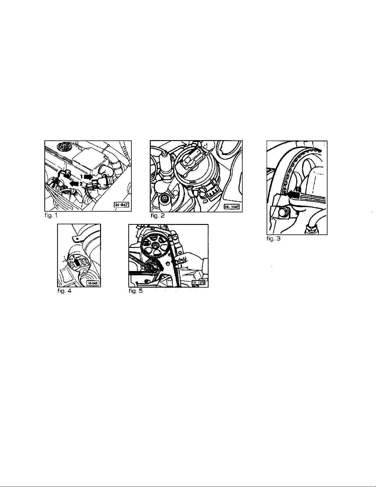
control valve (fig 1, disregard arrows.) Disconnect the electrical connector at the fuel after-run control valve. Remove the
eight nuts holding the valve cover down. Lift off valve cover while taking care not to damage the rubber valve cover gasket.
2.Move camshaft sprocket to cylinder number one TDC mark by turning the crankshaft clockwise with a 19mm socket until
the dot on the camshaft pulley lines up with the upper edge of the camshaft drive belt inner cover (fig 3.) Check TDC by
removing the distributor cap and making sure that the rotor is lined up with the notch on the distributor (fig 2.) The flywheel
should also be at TDC (fig 4.) If these marks do not line up, you will need to continue to rotate the crankshaft until they do.
3.Loosen belt tensioner with a 15mm open end wrench and slide off the camshaft drive belt, while keeping the belt tension on
the lower sprockets so that they don’t move or slip. If they do, you will probably have to re-align them in a time consuming
procedure described separately. By tying the belt via a bungee or other cord to the hood or laying the belt towards the rear
using a weight (wrench etc…) to keep the belt tension, you can install the cam without having to re-align all of the lower
sprockets.
4.Remove bearing caps one and three, in that order. Take note of which end of each cap is pointing towards you. Caution: The
bearing caps are offset, and will break if re-installed backwards and tightened down. Next, remove the nuts from bearing caps
two and five a little at a time and crosswise so that the spring tension is evenly relieved. Lift cam with attached sprocket out
of the head.
5.Loosen the camshaft sprocket bolt 1/2 to ¾ turn and tap the sprocket loose using a soft faced hammer. Remove the bolt
completely and remove the sprocket, woodruff key, and cam seal. Lightly coat the cam seal with oil and place on the new
camshaft. Install the woodruff key and sprocket onto the new camshaft and for A1, A2, A3 and Corrado G60 motors, torque
the cam sprocket mounting bolt to 59 ft/lb. For A4 2.0 8v motors, tighten the cam sprocket mounting bolt to 74 ft/lb
6.Apply oil to the bearing surfaces, and a small amount of assembly lube to the lobes of the new camshaft. Lay the camshaft in
the head with the lobes for the number one cylinder facing up. Install bearing caps two and five, tightening down gradually
and crosswise until the camshaft is pushed completely in to the bearing saddles. Install the remaining bearing caps and
torque all nuts to 15 ft/lb.
7.Check to see if the dot on the inside of the cam sprocket lines up with the upper edge of the camshaft drive belt inner cover
(fig. 1.) If not, rotate cam slightly until it does.
8. Slide camshaft belt over cam sprocket, taking care not to disturb the alignment of the camshaft sprocket.
Page 2
9. Re-install valve cover, tightening the nuts to 7 ft/lb.
10. Using a special spanner wrench (AST P/N 10.012.86400 or equiv.), tighten the drive belt by rotating the tension pulley in the
direction of the arrow (fig. 5). The belt should feel tight when twisted 90 degrees with the thumb and forefinger, halfway
between the camshaft and intermediate shaft pulleys. Tighten the pulley retaining nut to 33 ft/lb.
11. Turn crankshaft two complete revolutions and check belt tension, camshaft alignment, crankshaft alignment, and distributor
alignment. If everything checks out, re-install distributor cap, timing belt cover, idle stabilizer valve assembly, brackets,
crankcase ventilation hose assembly, and after-run control valve connector.
12. Start engine and run it at around 2000 RPM for twenty minutes. This is the crucial break-in period for a new cam. It is
important that the cam has good oil pressure at this time! Once twenty minutes are up, you’re ready to run.
IMPORTANT! The blue coolant temperature sender must be disconnected when checking or adjusting ignition timing.
Page 3

Installation Instructions
Drive Belt/Alignment Procedure for G60 models
Note:
The following steps assume that the timing belt has slipped during camshaft installation or has otherwise lost tension below
the intermediate shaft pulley. This procedure outlines how to get the motor back into time.
Procedure:
1. Loosen, but do not remove the lug nuts on the passenger side road wheel. Jack up the passenger side of the car and support
it with a jackstand. Remove road wheel. Remove plastic inner wheel housing liner/splash shield with an 8mm socket.
2. Loosen the water pump pulley bolts. Loosen the A/C and alternator mounting bolts. Loosen adjusting screws to provide
the slack required to remove the belts. The tensioning mechanism for the A/C compressor is in the form of a bolt that is part
of the mounting bracket itself. Remove the water pump pulley and the lower belt.
3. Remove the lower drive belt cover by removing the two nuts and bolt that hold it to the water pump and front of the
motor. Remove all four spark plugs to allow the crankshaft to turn easier when you adjust it. Set motor to TDC (see step 2 of
instructions).
4. Your crankshaft vs. intermediate shaft timing should already be close if you put the motor at TDC before beginning your cam
install. Rotate crankshaft (by hand using a wrench or socket on the end of the crank) and intermediate shaft until the dot
from the intermediate shaft is visible through the “V” in the crankshaft pulley (fig 1.) Caution: Rotate the crankshaft the least
amount necessary to align the marks. Since the drive belt is not installed, there may be piston to valve interference if you try
to rotate the crankshaft too much.
5. Check camshaft timing mark, make sure that the dot on the inside of the cam sprocket is lined up with the camshaft drive belt
inner cover (fig 1).
6. Install the camshaft drive belt by sliding it over the sprockets. Start at the crankshaft, then the intermediate shaft, and finally
the camshaft. Try to keep the belt as tight as possible between the crankshaft and the intermediate shaft, and between the
intermediate shaft and the camshaft sprockets.
7. Using a special spanner wrench (AST P/N 10.012.86400 or equiv.), tighten the drive belt by rotating the tension pulley in the
direction of the arrow (fig. 2). The belt should feel tight when twisted 90 degrees with the thumb and forefinger, halfway
between the camshaft and intermediate shaft pulleys. Tighten the pulley retaining nut to 33 ft/lb.
 Loading...