

Page 1
A U T O T E C H
A2/A3 = 29.0 in
A4/B5 = 25.0 in
Installation Instructions
www.autotech.com
Part Number: 10.525.1628K
Description: rear swaybar installation for B5 chassis
Notes: These performance swaybars utilize Autotech’s unique sliding endlink design
that prevents binding of the bar (and preloading of the suspension) due to
locational differences between the mounting points of the rear suspension and the
swaybar itself.
TOOLS REQUIRED: PARTS LIST:
1. jackstands 1. rear swaybar
2. electric drill and 1O.5mm (27/64")bit 2. (4) poly bushings
3. silicone lubricant 3. (4) steel ring mounts
4. metric wrenches, 13 to 17mm 4. (2) 1Omm rod ends
5. tape measure 5. (6) 1Omm hardened washers
6. moly grease 6. (2) 1Omm nylock nuts
7. (2) M10x100 shock bolts
Procedure:
1. Apply a generous amount of waterproof grease to the inside of the bushings, and some silicone spray along each of the bends on the swaybar.
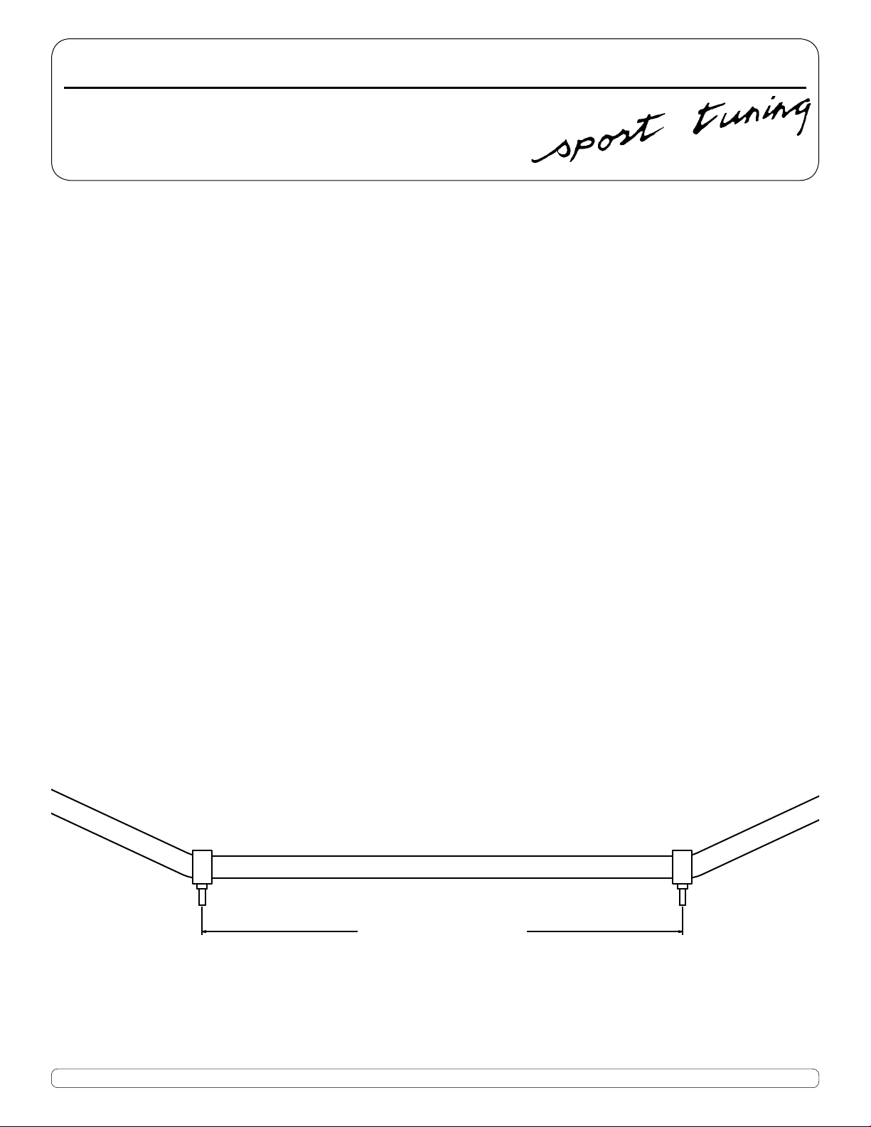
2. Slide the two inboard mounts onto the swaybar and push them past both bends so that
they end up on the middle, straight section of the swaybar. The inboard mounts will be
installed on the axlebeam when they are as far apart from each other as possible without overlapping any of the bends on the bar. Measure, and take note of this distance.
The distance from stud to stud on the inboard mounts should be approximately as follows:
B5 Chassis = 25 inches
3. Raise the rear of the car and place it on jackstands. Be sure that the car is in gear, the
front wheels are chocked, and that it cannot roll.
Phone 949.240.4000 Fax 949.240.045032240-E Paseo Adelanto, San Juan Capistrano, CA 92675
Page 2
(cont.)
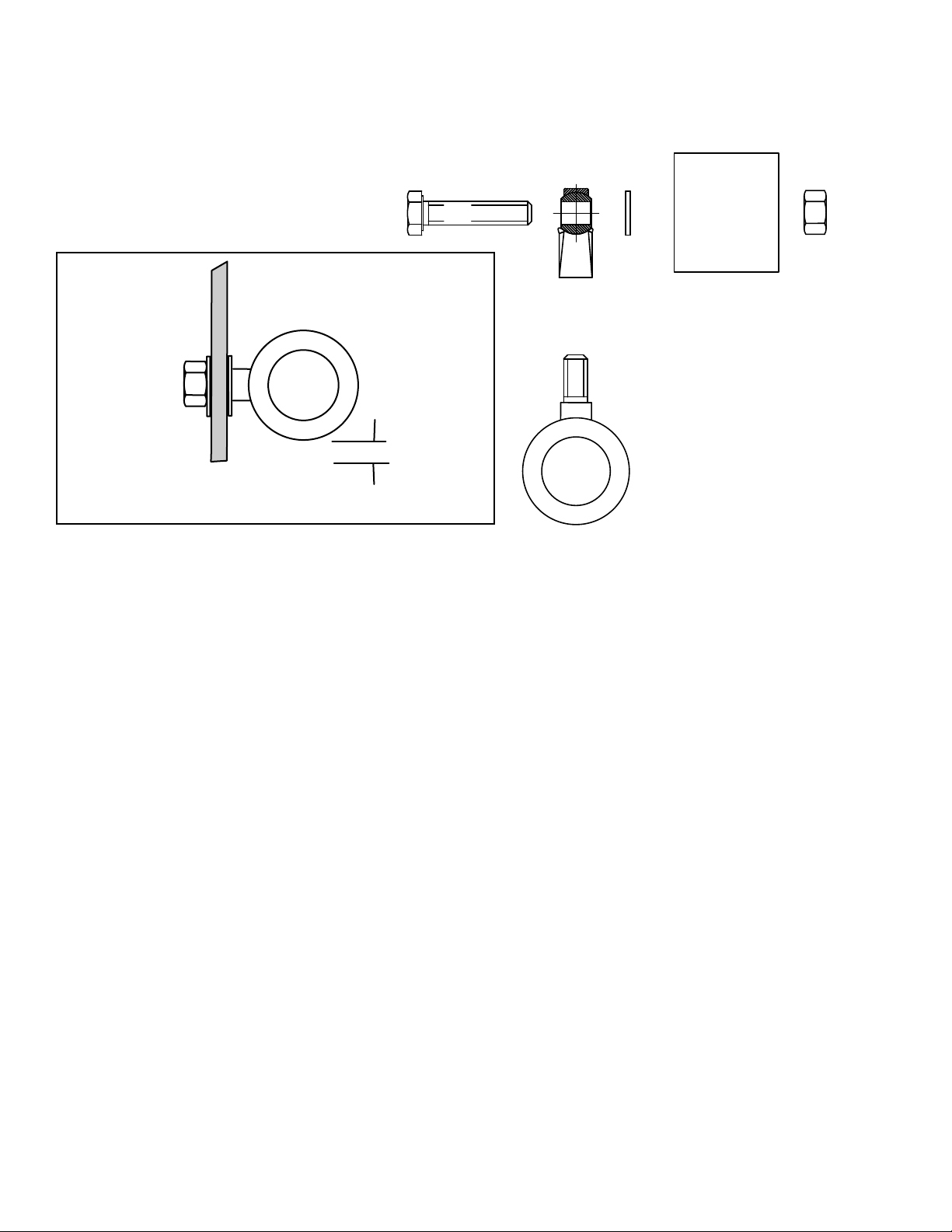
rear shock
mount
factory nut
new longer bolt
rod end
washer
jam nut
ring mount
with bushing
Passat rear axlebeam section - side view
min 1/4 inch
4. Mark the axlebeam's crossmember for the hole locations using the distance you measured in
step 1. The holes should be centered left-to-right (12.5 inches each side of the centerpoint).
Use the tape to measure 1.5 inches up from the bottom edge of the crossmember.
rear view of endlink assembly
5. Drill the two 1O.5mm (13/32" - 27/64") holes in the crossmember. It is a good idea to drill a
pilot hole first so that the larger drill bit does not have to work so hard.
6. Mount the outboard rod ends on the car. The supplied longer shock bolts should go first
through the rod end, next through the washer, then into the lower shock mount. Use the
original nut to fasten the new bolt.
7. Thread the remaining two bar mounts into the rod ends.
8. Push each end of the swaybar into the end bushings. A small amount of silicone lubricant or
a film of moly grease applied to the bar end and bushing eases the task.
9. Now swing the swaybar forward in order to push the inboard mounting studs through the
drilled holes in the crossmemeber. Be sure to capture a washer on each side of the hole
before attaching each inboard mount with the nylock nut.
10. Check all fasteners to be sure they are tightened properly.
 Loading...