

Page 1
AUTOTECH
Installation Instructions
Part Number: 10.215.300, 320K, 330K; 10.215.360, 361
Description: Autotech Q-Chip Installation in Corrado VR6 and G60
Notes: The Autotech Q-chip is designed to operate within factory idle mixture settings, and
with all emissions-related parts functioning and in place. No further adjustment is necessary. Fuel with an o
Caution! Be aware that E-PROM's are static-sensitive devices, and so are the chips in your control
unit. Avoid replacing chips in high static areas, and avoid touching the pins of any integrated circuit
or E-PROM.
1. Open hood and remove the rubber seal laying on the top edge of the firewall. Lift the plastic
raincover and locate the control unit. It is located towards the center of the raintray. Remove the
fresh air duct cover (leaf screen) by sliding out the retaining clip (best done using a long standard
screwdriver, rather than your fingers), then lifting up and sliding out the leaf screen.
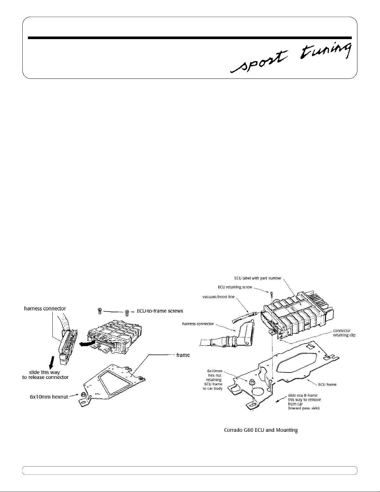
2. Remove the harnesss connector on G60 models by pulling back on the steel retaining tab, and
rotating the forward end of the connector away from the control unit. Remove the harness
connector on VR6 models by sliding the black pull tab parallel to the connector (towards the front
of the car). Doing this This will push the entire connector out as it rides in pins on the ECU. Next,
remove the 10mm nut holding the control unit frame to the body of the car. Slide out the frame/
control unit. It is a tight fit but it will come out over the fresh air duct. Separate the control unit
from the frame by removing the two Phillips head screws holding them together. With the screws
removed, slide the control unit off the frame.
ctane rating of 92 or higher is recommended.
Corrado VR6 ECU and Mounting
3. To open the control unit, use a Phillips screwdriver or a Torx driver (depends on control unit) to
remove the four screws at the connector end, (and at the heat sink end on G60) and slide the
electrical section out of the black outer case.
Phone 949.240.4000 Fax 949.240.045032240-E Paseo Adelanto, San Juan Capistrano, CA 92675
Page 2
VR6 Models
4. Examine the chips on the board. The chip that you will be replacing will be the only one set into a
socket, and will usually have a white "H" shaped plastic retainer covering it. If you do not see any
socketed chips, call Autotech before proceeding any further.
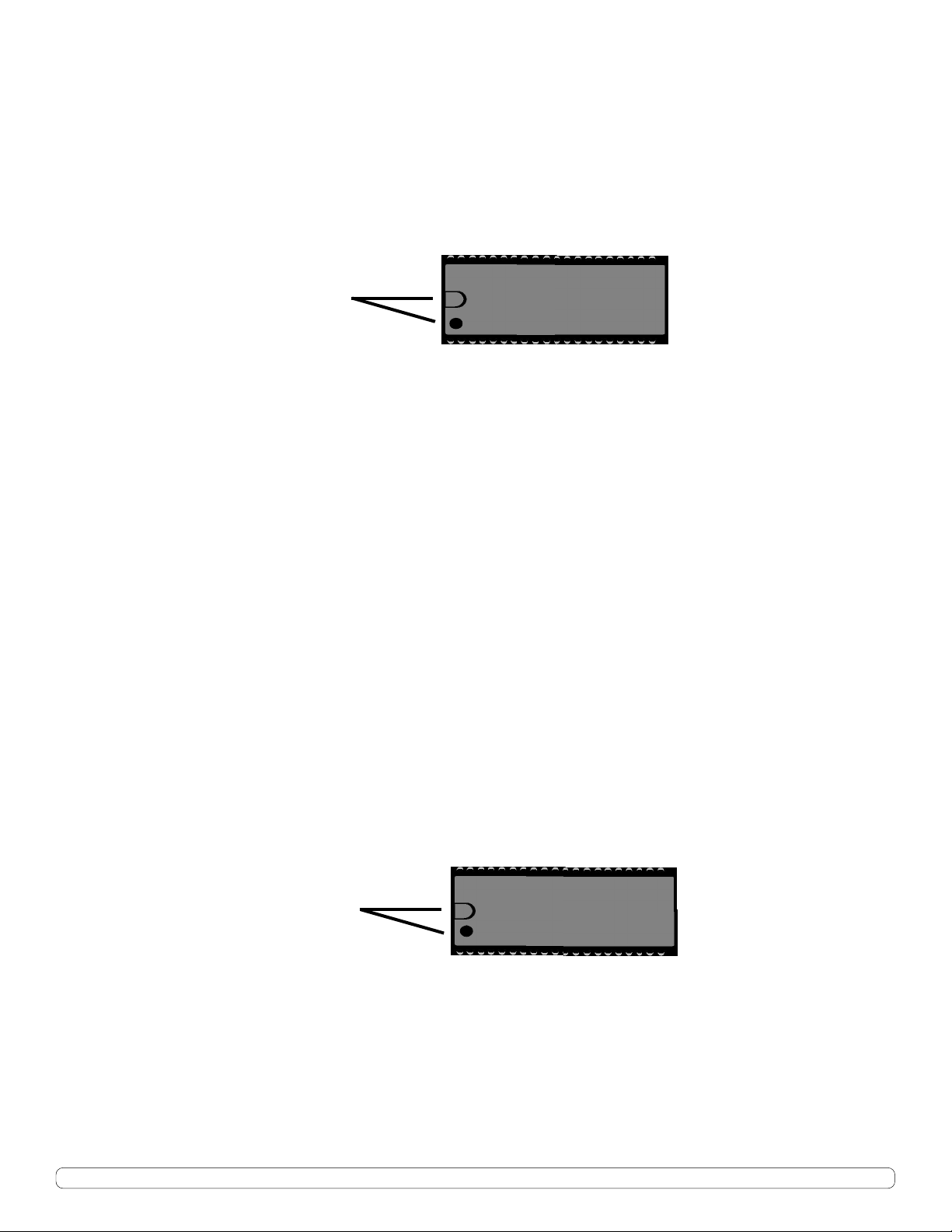
5. Before removing the stock chip, take note of the location of the notch at the top of the chip. It is
mandatory that the Q-chip be installed in exactly the same position! If you install the Q-chip
backwards, you will damage your control unit as well as the Q-chip. Remove the stock chip by first
removing the white retaining clip, then gently pry out the chip from the socket, using a small
screwdriver between the two. Note! To prevent bending the pins, change sides often until the chip
is completely removed. Autotech will not be responsible for chips with pin damage.
Note notch or dot
position.
Note: The socket should also have a corresponding notch or dot to aid in correct alignment.
6. Insert the Q-chip into the socket only after you have double-checked that it is in the same position
as the original. Gently place it into the socket while ensuring that all the pins are going smoothly
into the socket holes. Now, lightly press the chip all the way down into the socket, while checking
that no pins are bending during installation. Re-install the plastic retaining clip and place your
stock chip inside the anti-static box from the Q-chip for safe keeping. Reverse the control unit
opening and removal steps listed above to finish your installation.
G60 Models
4. Remove the black "push pins" on the upper (smaller) printed circuit board and move the white
plastic off to the side. Remove the two screws holding the upper printed circuit board to the
harness connector and lift the printed circuit board up off of the plastic posts by closing them
with needle-nosed pliers and lifting on the board. The board will then pivot on the ribbon connector.
5. Remove the stamped steel RFI cover from the upper (smaller) printed circuit board by removing
the five nuts and screws keeping the two halves together. The chip will be in a socket and will have
a printed number "1 267 xxx xxx" or "FAEB xxx" on it. There will only be one chip in the whole ECU
that will be socketed. If you are unsure which chip to remove, call Autotech before going any
further!
6. Before removing the stock chip, take note of the location of the notch at the top of the chip. It is
mandatory that the Q-chip be installed in exactly the same position! If you install the Qchip backwards, you will damage your control unit as well as the Q-chip. Remove the stock chip by
gently prying out the chip from the socket, using a small screwdriver between the two. Note! To
prevent bending the pins, change sides often until the chip is completely removed. Autotech will
not be responsible for chips with pin damage.
Note notch or dot
position
7. Insert the Q-chip into the socket only after you have double-checked that it is in the same position
as the original. Gently place it into the socket while ensuring that all the pins are going smoothly
into the socket holes. Now, lightly press the chip all the way down into the socket, while checking
that no pins are bending during installation. Place your stock chip inside the anti-static box from
the Q-chip for safe keeping. Reverse the control unit opening and removal steps listed above to
finish your installation.
Phone 949.240.4000 Fax 949.240.045032240-E Paseo Adelanto, San Juan Capistrano, CA 92675
 Loading...