

Page 1
User Guide
EPIC-IP
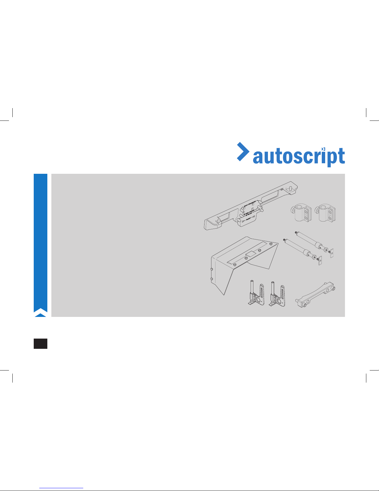
MT-BL Studio Box Lens Mounting Kit and Hood
Intelligent Prompting Monitors and Accessories
EN
www.autoscript.tv
www.progl-gerlach.de
Intelligent Prompting System
Page 2

Copyright © 2017
All rights reserved.
Original Instructions: English
All rights reserved throughout the world. No part of this publication may be stored in a retrieval system, transmitted, copied or reproduced in any
way, including, but not limited to, photocopy, photograph, magnetic or other record without the prior agreement and permission in writing of the Vitec
Group Plc.
Disclaimer
The information contained in this publication is believed to be correct at the time of printing. Vitec Videocom Ltd reserves the right to make changes
to the information or specications without obligation to notify any person of such revision or changes. Changes will be incorporated in new versions
of the publication.
We are making every eort to ensure that our publications are updated on a regular basis to reect changes to product specications and features.
Should this publication not contain information on the core functionality of your product, please let us know. You may be able to access the latest
revision of this publication from our website.
Vitec Videocom Ltd reserves the right to make changes to product design and functionality without notication.
Trademarks
All product trademarks and registered trademarks are the property of The Vitec Group Plc.
All other trademarks and registered trademarks are the property of their respective companies.
Published by:
Vitec Videocom Ltd
Email: [email protected]
!
WARNING! This manual accompanies the Prompter User Guide A9010-4980.
Before attempting to install, consult the safety advice in the prompter user guide A9010-4980.
Page 3
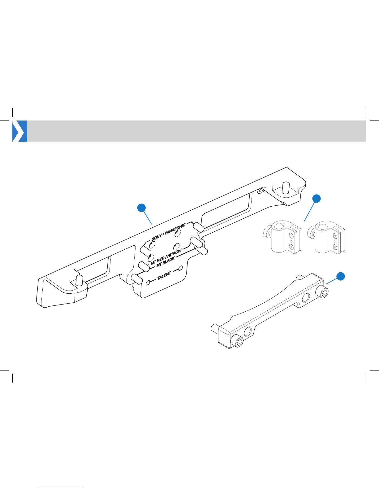
MT-BL LEGACY ADAPTOR KIT
This additional mounting kit is required for EVO-IP and EPIC-IP
on-camera systems when using a Studio Box Lens.
Components and Connections
1
2
3
Page 4
2
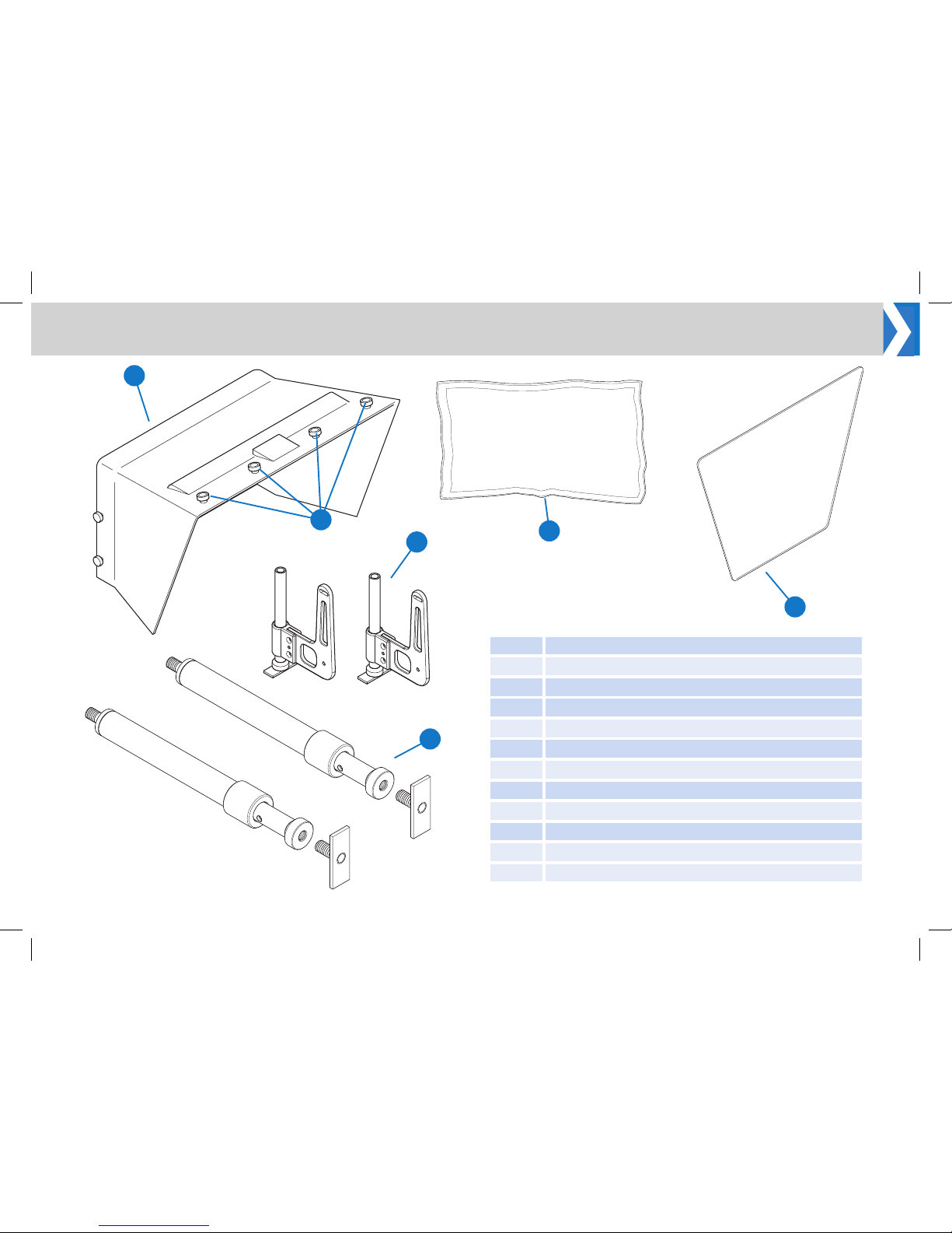
1 Legacy Backplate Assy
2 Legacy Hood Bracket Assy
3 Vinten Wedge Adaptor Bracket Assy.
4 Glass for Moulded Hood-Wide (MH-W)
5 Lightshield for Moulded Hood (LIGHTSPEED-L)
6 Wide Moulded Hood (MH-WUP)
7 Moulded Hood - Side Brackets (MH-SIDEBKT)
8 Moulded Hood - Glass Hardware Kit (RGMH-W)
9 1 x Pair of 12” telescopic rods (TR-12)
10* Moulded Hood - 12” metal work (MH-LWRI)
11* Wide Moulded Hood - 23” metal work (MH-WWRI)
* Not Illustrated
Components and Connections
9
6
8
5
7
4
Page 5
3
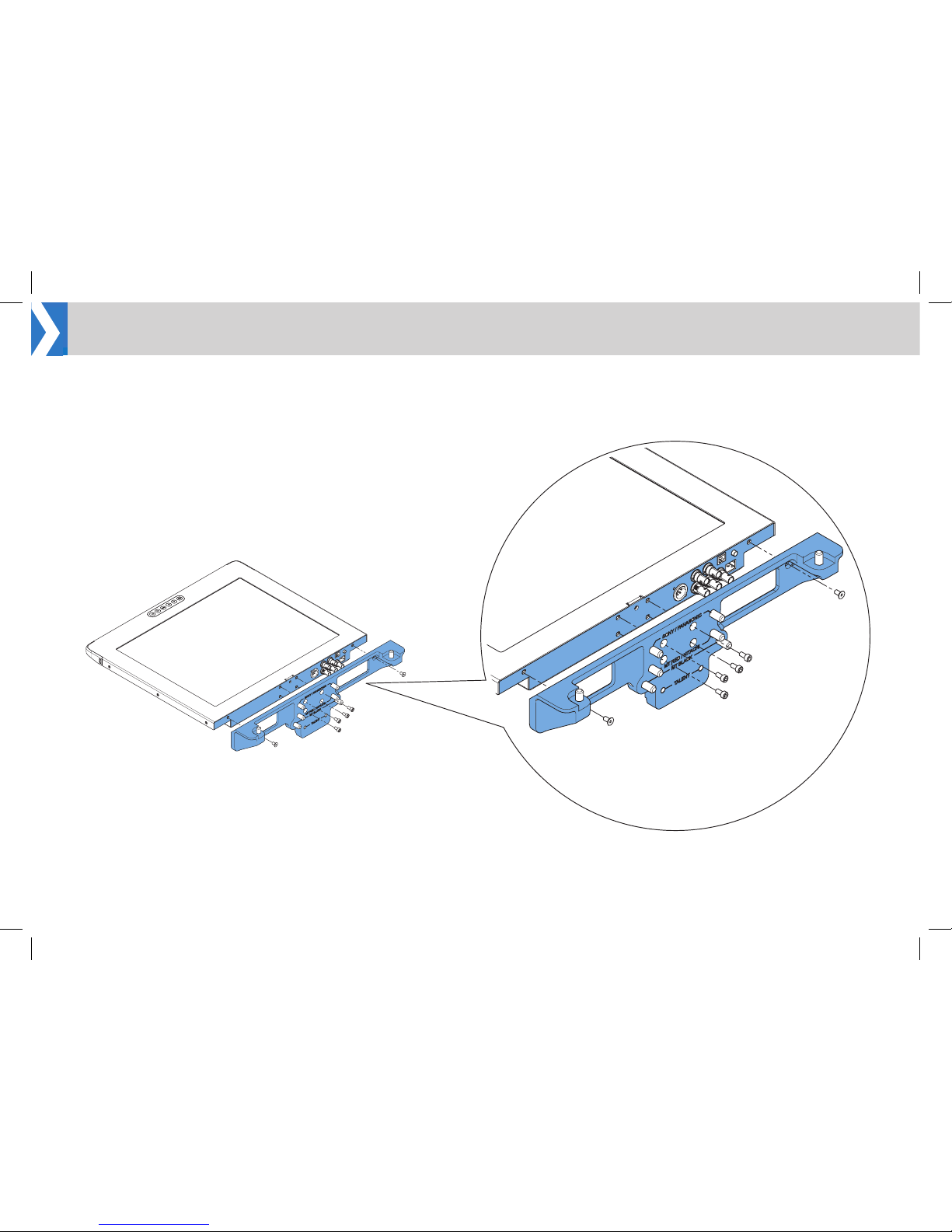
Installation
1. Oer the hood mounting bracket to the rear panel of the prompt
monitor.
2. Locate the monitor into the mounting bracket recess.
3. Secure the bracket to the monitor; rst using the 2 outer 10mm M5
socket screws, then x the 4 x centre 16mm M5 socket screws.
Attach Legacy Adaptor to the Prompt Monitor
Page 6
4
Installation
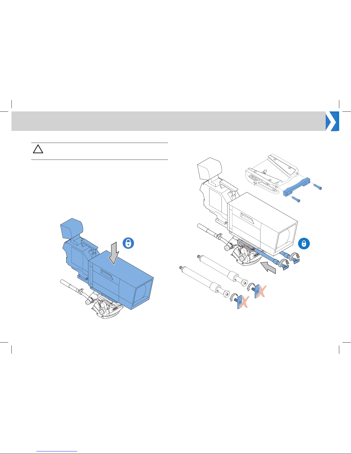
A pair of telescopic rods must be used to mount the prompter system.
A camera mounting plate must be tted between the head support and
the camera body to allow installation of the prompter system. Dierent
sizes of mounting plates are available, depending on the type of
camera being used.
Direct Mounting to the Camera Head Support
1. Fit the camera and any xing plate being used, to the top of the
camera head support.
Assemble the MT-BL Legacy Adaptor Kit
!
WARNING! Before attempting to install or adjust the
prompter assembly, the tilt axis of the head support must
be securely locked horizontally (tilt axis).
2. Screw TR-12 telescopic rods into the mounting holes on the front
of the camera head support. Note! If using the Vinten wedge
plate, attach the wedge adaptor bracket, this will allow the rods to
be mounted to the plate.
3. Remove the end plates from the telescopic rods and store
somewhere safe, they will not be required for this set up.
Page 7
5
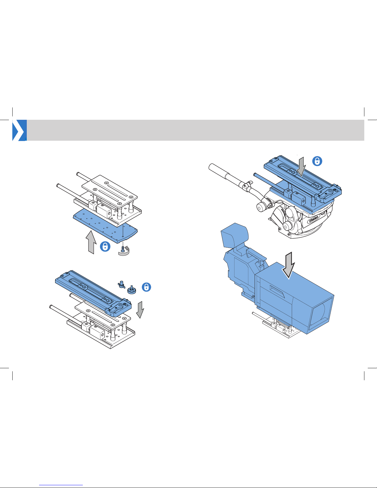
MT-BLACK Mounting Plate
1. Fit the camera head support plate to the base of the MT-BLACK
mounting plate.
Installation
2. Fit the mounting plate for the camera being used to the top of the
MT-BLACK mounting plate, using the xing screws provided.
3. Fit the MT-BLACK mounting plate to the camera support.
4. Fit the camera to the
top of the MT-BLACK
mounting plate.
Page 8
6
Installation
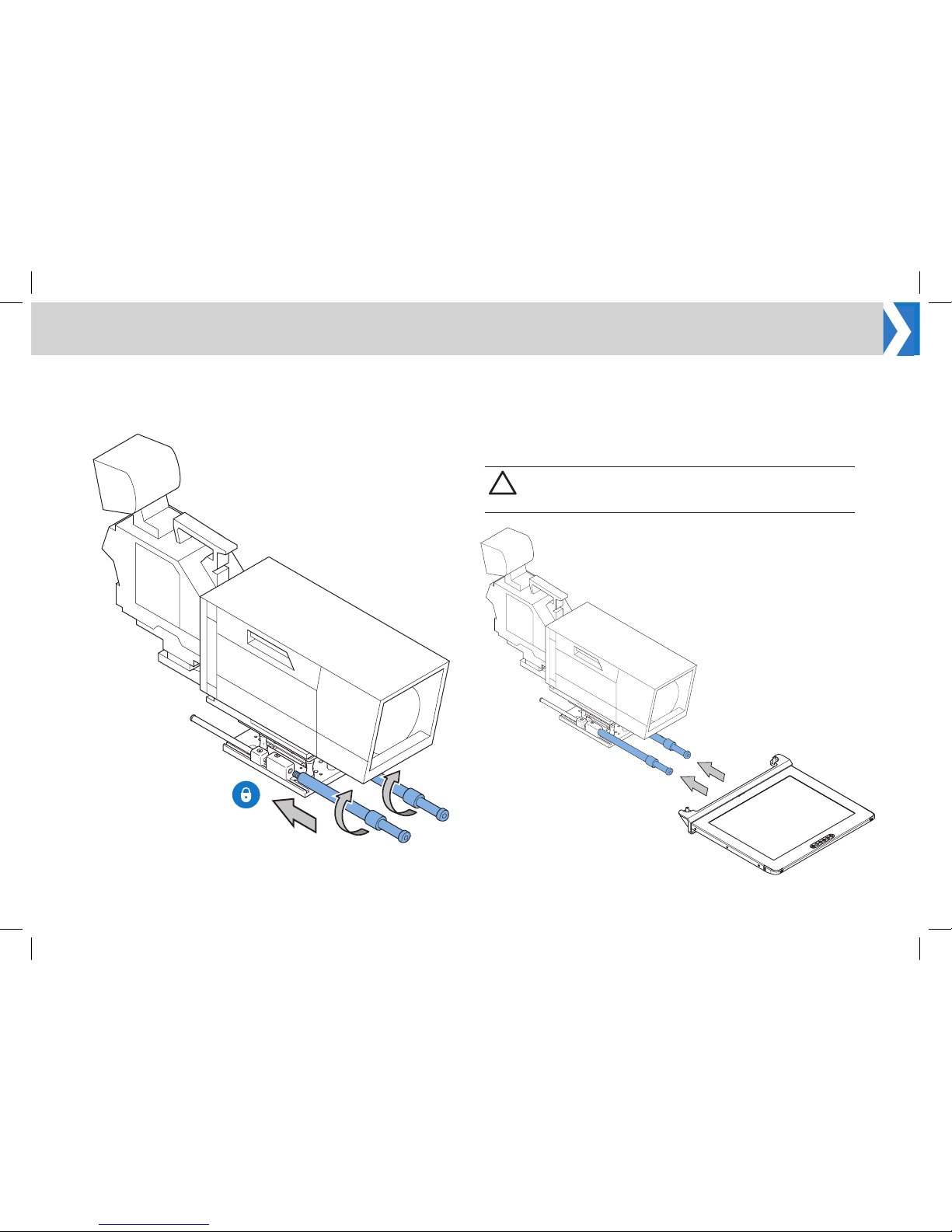
5. Screw the telescopic rods (TR-12) into the mounting blocks on the
MT-BLACK mounting plate.
Mounting the Monitor
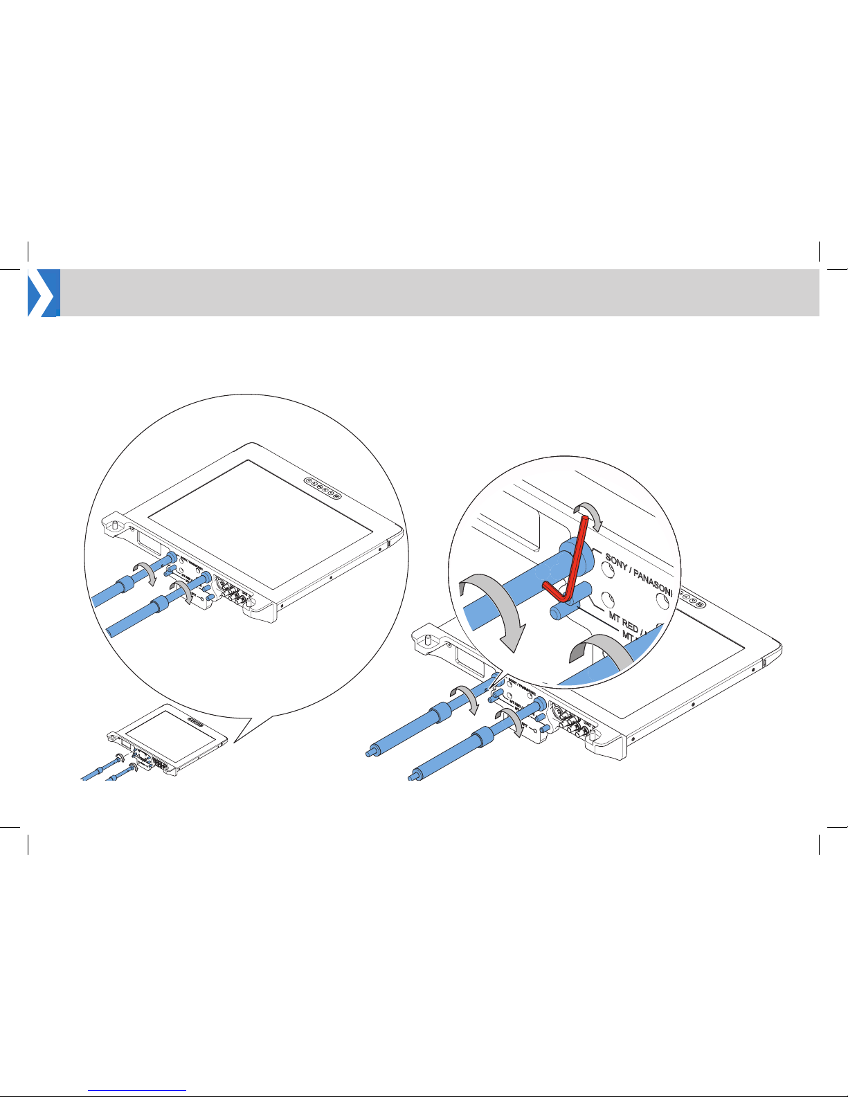
The Legacy Backplate has 3 mounting positions.
a. Sony / Panasonic (Top)
b. MT RED / Hitachi (Middle)
c. MT BLACK (Bottom)
!
CAUTION! It is advised that two people attach the monitor
to the telescopic rods, one supporting the monitor while
the other screws in the rods.
Page 9
7
1. Oer the monitor backplate to the telescopic rods.
2. Using the most suitable mounting points on the backplate, screw
the rods to the backplate.
3. Tighten the xing by Inserting a small Allen key or similar into the
hole in the telescopic rod to provide leverage.
Installation
Page 10
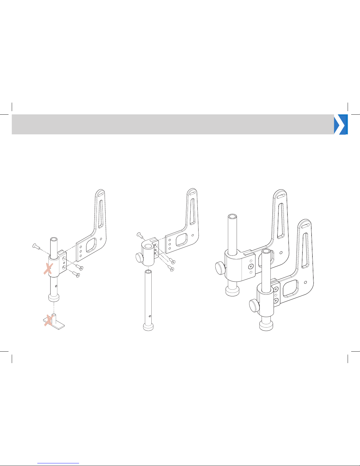
8
Assembling and Fitting the Hood
1. Dismantle the original brackets x2 and store items (a) and (b)
below as they will not be required for this set up.
2. Replace (a) with the new oset bracket, ensure the osets are on
the inside as shown in picture 3.
a
b
1 2 3
Installation
Page 11
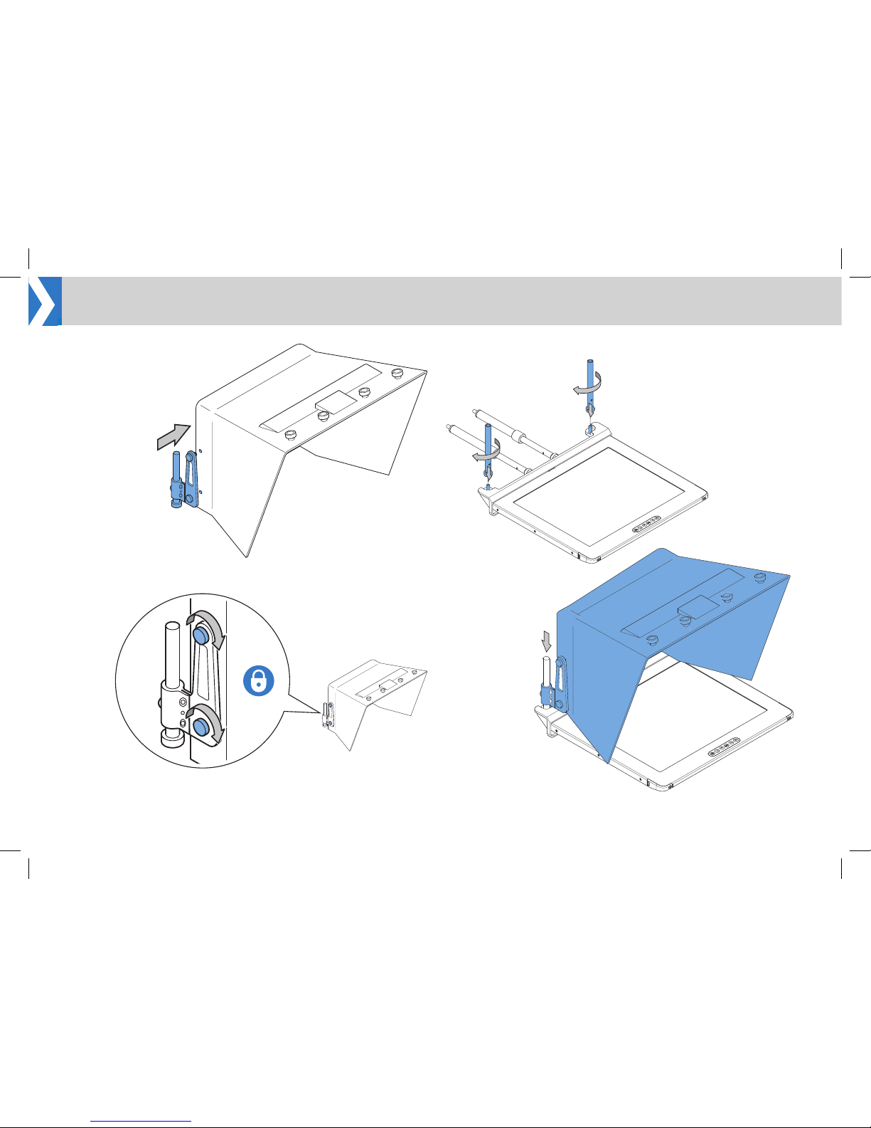
9
1. Align the hood
bracket and two
xing screws with
the holes in the
side of the hood.
2. Tighten the xing
screws to secure
the hood bracket
in position.
3. Repeat steps 1 and 2 for the opposite hood bracket.
4. Remove the rods from the bracket and screw onto the hood
mountings.
5. Slide the hood brackets
and hood onto the
rods.
6. Lock into position using the bracket lock knobs.
Installation
Page 12
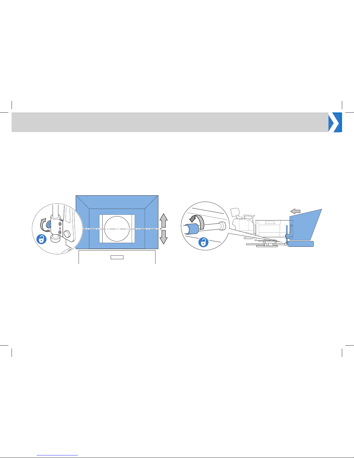
10
Adjusting the Vertical Hood Position
The vertical position of the hood must be adjusted to centralise it with
the camera lens.
1. Loosen the two lock screws to adjust the position of the hood on
the rods.
2. Adjust the vertical position of the hood to centralise it with the
camera lens and fully re-tighten the lock screws.
Adjusting the Prompter Assembly Position
The horizontal position of the prompter assembly must be adjusted to
optimise its position relative to the camera position.
1. Loosen the twist locks on the telescopic rods and move the
prompter assembly back until the hood overlaps the camera lens.
2. Tighten the twist locks to secure the assembly.
Installation
Page 13
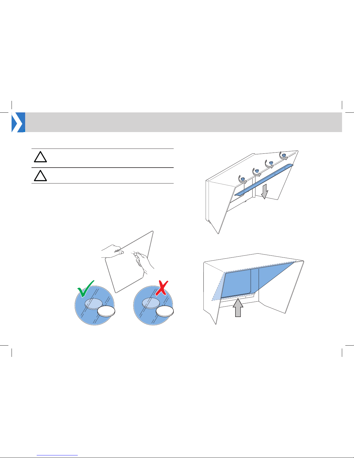
11
Fitting the Reective Glass Panel
Fitting Glass Panel
1. Remove all the xing screws from the top of the hood to release
the top glazing bar.
!
WARNING! Risk of personal injury or injury to others.
Care must be taken when handling and installing the
reective glass panels.
!
WARNING! Only use the correct size glass panel designed
for the installed hood.
When the hood has been installed, the reective glass panel can be
tted to the prompter assembly.
Panel Orientation
For the EPIC-IP prompter to display images, it is essential that the
reective side of the glass is installed facing outwards. The reective
side of the glass can be established as follows:
Carefully hold a blunt
object such as a coin
against the surface of the
glass.
If the object is being held
against the reective side,
there will be no gap (depth
of the glass) before the
reection.
2. Carefully position the glass panel on the bottom glazing bar inside
the hood.
Installation
Page 14
12
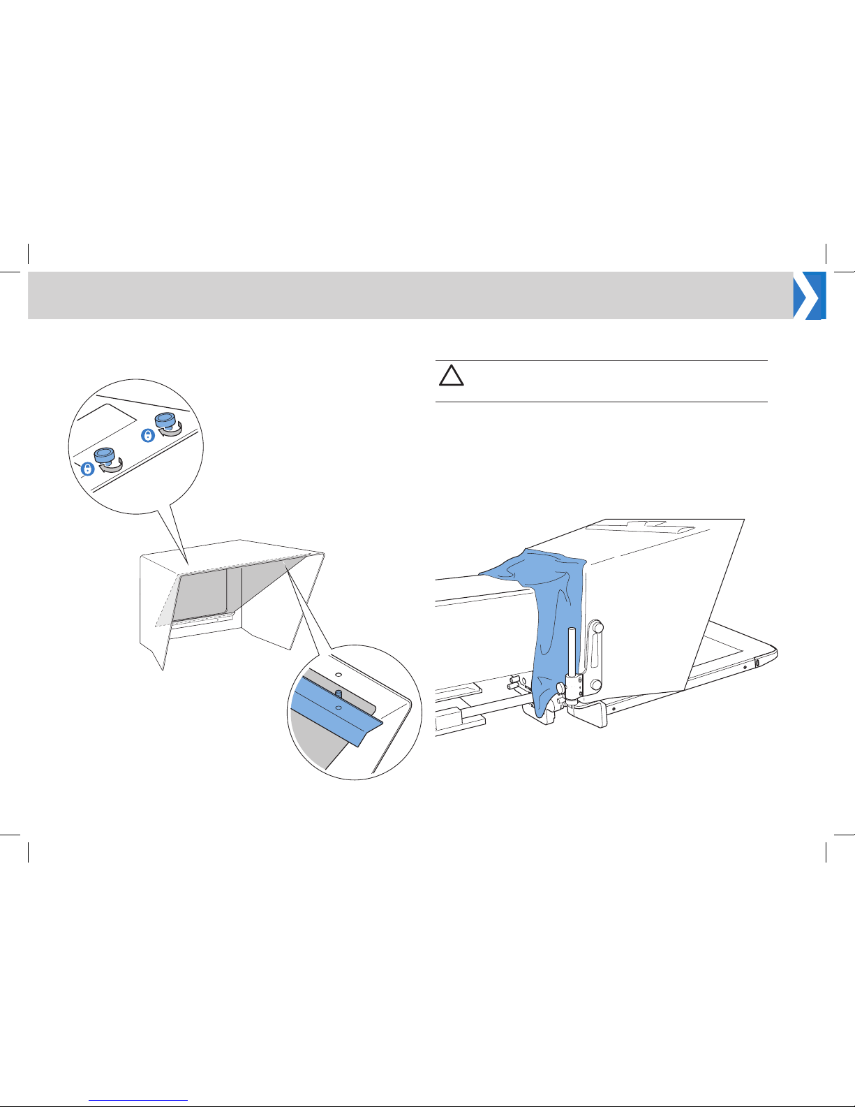
Fitting the Light Shield Cloth
!
CAUTION! Ensure that the light shield cloth is only loosely
tted around the body of the servo lens to allow it to
continue operating freely.
1. Secure the light shield cloth to the Velcro strips on the rear of the
hood.
3. With the glass supported at all times, replace the top glazing bar
and secure with the xing screws.
Installation
Page 15

Page 16

Publication No. A9010-4981/0
www.autoscript.tv
www.progl-gerlach.de
For assistance you can contact Progl+Gerlach. +49 (0)89 43 509 712 or [email protected]
 Loading...