

Page 1
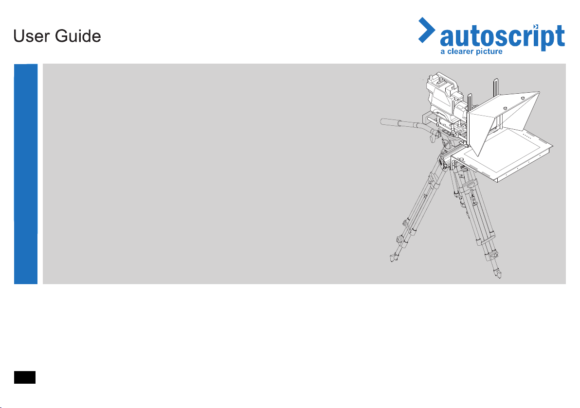
ELP 15 PLUS
On-Camera Prompter
On-Camera Prompter
ELP 15 PLUS
Part No. ELP15PLUS-ME
EN
www.autoscript.tv
Page 2

Copyright © 2014
All rights reserved.
Original Instructions: English
All rights reserved throughout the world. No part of this document may be stored in a retrieval system,
transmitted, copied or reproduced in any way, including, but not limited to, photocopy, photograph,
magnetic or other record without the prior agreement and permission in writing of the Vitec Group plc.
Disclaimer
The information contained in this manual is believed to be correct at the time of printing. Vitec Videocom
Ltd reserves the right to make changes to the information or specifications without obligation to notify any
person of such revision or changes. Changes will be incorporated in new versions of the publication.
We are making every effort to ensure that our manuals are updated on a regular basis to reflect changes
to product specifications and features. Should this manual not contain information on the core functionality
of your product, please let us know. You may be able to access the latest revision of this manual from our
website.
Vitec Videocom Ltd reserves the right to make changes to product design and functionality without
notification.
Trademarks
All product trademarks and registered trademarks are the property of The Vitec Group Plc.
All other trademarks and registered trademarks are the property of their respective companies.
Published by:
Vitec Videocom Ltd
Supports Technical Publications Department
Western Way, Bury St Edmunds
Suffolk IP33 3TB
United Kingdom
Email: [email protected]
Page 3

Contents
Safety. . . . . . . . . . . . . . . . . . . . . . . . . . . . . . . . . . . . . . . . . . . . . . . . . 2
About this Manual . . . . . . . . . . . . . . . . . . . . . . . . . . . . . . . . . . . . . . 3
Components and Connections . . . . . . . . . . . . . . . . . . . . . . . . . . . . 4
On-Camera Prompter Key Components. . . . . . . . . . . . . . . . . . . 4
Prompter Installation Components . . . . . . . . . . . . . . . . . . . . . . . 5
Box Contents . . . . . . . . . . . . . . . . . . . . . . . . . . . . . . . . . . . . . . . 5
Tools Required . . . . . . . . . . . . . . . . . . . . . . . . . . . . . . . . . . . . . . 7
Prompter Monitor Connections . . . . . . . . . . . . . . . . . . . . . . . . . . 6
Prompter Monitor Control Panel . . . . . . . . . . . . . . . . . . . . . . . . . 6
Installation . . . . . . . . . . . . . . . . . . . . . . . . . . . . . . . . . . . . . . . . . . . . 7
Mounting the Camera and Extrusion . . . . . . . . . . . . . . . . . . . . . 7
Mounting the Prompter Monitor . . . . . . . . . . . . . . . . . . . . . . . . . 9
Assembling and Fitting the Hood . . . . . . . . . . . . . . . . . . . . . . . 10
Adjusting the Prompter Assembly Position. . . . . . . . . . . . . . . . 12
Fitting the Reflective Glass Panel. . . . . . . . . . . . . . . . . . . . . . . 13
Fitting the Light Shield Cloth. . . . . . . . . . . . . . . . . . . . . . . . . . . 14
Fitting the Counterbalance Weights . . . . . . . . . . . . . . . . . . . . . 15
Balancing and Adjustments . . . . . . . . . . . . . . . . . . . . . . . . . . . 15
Connecting the Prompter Monitor. . . . . . . . . . . . . . . . . . . . . . . 17
Powering Up . . . . . . . . . . . . . . . . . . . . . . . . . . . . . . . . . . . . . . . 18
Configuration . . . . . . . . . . . . . . . . . . . . . . . . . . . . . . . . . . . . . . . . . 19
Control Panel Buttons . . . . . . . . . . . . . . . . . . . . . . . . . . . . . . . 19
Monitor Function OSD Menus . . . . . . . . . . . . . . . . . . . . . . . . . 19
Maintenance . . . . . . . . . . . . . . . . . . . . . . . . . . . . . . . . . . . . . . . . . . 21
Troubleshooting. . . . . . . . . . . . . . . . . . . . . . . . . . . . . . . . . . . . . . . 22
Technical Specification . . . . . . . . . . . . . . . . . . . . . . . . . . . . . . . . . 23
General Notices . . . . . . . . . . . . . . . . . . . . . . . . . . . . . . . . . . . . . . . 24
1
Page 4
Safety
Important information on the safe installation and operation of
this product. Read this information before operating the product.
For your personal safety, read these instructions. Do not operate
the product if you do not understand how to use it safely. Save
these instructions for future reference.
Warning Symbols Used in these Instructions
Safety cautions are included in these instructions. These safety
instructions must be followed to avoid possible personal injury and
avoid possible damage to the product.
WARNING!
Where there is a risk of personal injury or injury to others,
comments appear supported by the warning triangle symbol.
Where there is a risk of damage to the product, associated
equipment, process or surroundings, comments appear
supported by the word ‘Caution’.
ELECTRIC SHOCK
Where there is a risk of electric shock, comments appear
supported by the hazardous voltage warning triangle.
Intended Use
The ELP 15 PLUS on-camera prompter has been designed to provide
a high quality teleprompting facility for television broadcasting.
The prompter is intended for use by television camera operators within
a TV studio environment or on outside broadcasts (OB) when protected
from weather by a suitable waterproof cover.
Health and Safety
WARNING! Risk of personal injury or injury to others. All
personnel must be fully trained and adhere to correct manual
handling techniques and Healthy & Safety regulations. It is
the responsibility of the local organisation to enforce safe
working practices at all times.
WARNING! Risk of personal injury or injury to others.
Care must be taken when handling and installing the
reflective glass panels. Always store spare glass panels in
the original packaging.
Electrical Connection
WARNING! Risk of electric shock. Always check cables for
signs of damage. Damaged cables can cause personal injury
and/or damage the equipment.
CAUTION! This product must be connected to a power
supply of the same voltage (V) and current (A) as indicated
on the product. Refer to the technical specifications for the
product.
CAUTION! Only use the power cable specified for this
product and certified for the country of use.
CAUTION! Using alternative power sources will invalidate
the system EMC liability.
CAUTION! Always use a fuse of the correct type and rating
for the product. Refer to the Technical Specifications for the
product.
2
Page 5
Safety and About this Manual
Mounting and Installation
WARNING! Before attempting to install or adjust the
prompter assembly, the tilt axis of the head support must be
securely locked horizontally.
WARNING! Do not install this product onto a camera
support or other equipment that is not designed to support
the weight of the product and its payload.
WARNING! Always ensure that all power and auxiliary
communications cables are routed so that they do not
present any danger to personnel. Take care when routing
cables in areas where robotic equipment is in use.
Water, Moisture and Dust
WARNING! Protect the product from water, moisture and
dust. The presence of electricity near water can be
dangerous.
WARNING! When using this product outside, protect from
rain using a suitable waterproof cover.
Ventilation
WARNING! Slots and openings are intended for ventilation
purposes to ensure reliable operation of the product, and
protect it from overheating. Do not block or cover any slots
and openings.
Operating Environment
CAUTION! The product should not be used outside the
operating temperature limits. Refer to the product technical
specifications for the operating limits for the product.
Cleaning
WARNING! Risk of electric shock. Always disconnect and
isolate the product from the power supply before cleaning.
CAUTION! Do not use solvent or oil-based cleaners,
abrasives or wire brushes.
Maintenance
WARNING! Servicing or repair of this product must only be
performed by qualified and trained electrical engineers.
WARNING! The fitting of non-approved parts and
accessories, or the carrying out of non-approved alterations
or servicing can be dangerous and could affect the safety of
the product. It may also invalidate the terms and conditions
of the product warranty.
About this Manual
This manual describes the installation of the ELP 15 PLUS onto a
suitable camera support as part of a full prompting system, using the
range of compatible mounting equipment available for various camera
configurations.
3
Page 6
Components and Connections
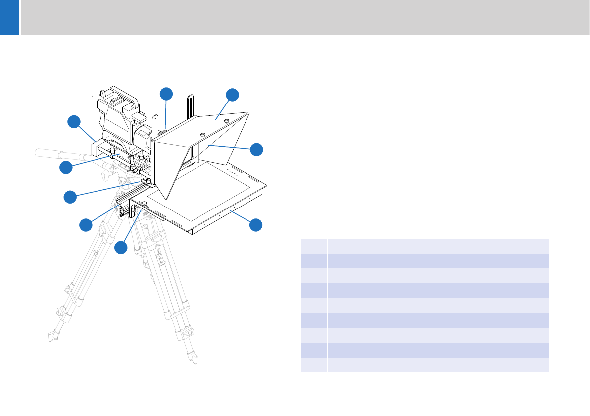
On-Camera Prompter Key Components
The illustration below highlights the key components used in a typical
prompter installation.
3
4
2
5
1
9
8
7
6
1 Camera mounting plate
2 Counterbalance weights
3 Blackout cloth
4 Hood
5 Reflective glass
6 LED TFT monitor display
7 Monitor mounting brackets
8 Main prompter mounting extrusion
9 Hood mounting brackets
4
Page 7
Components and Connections
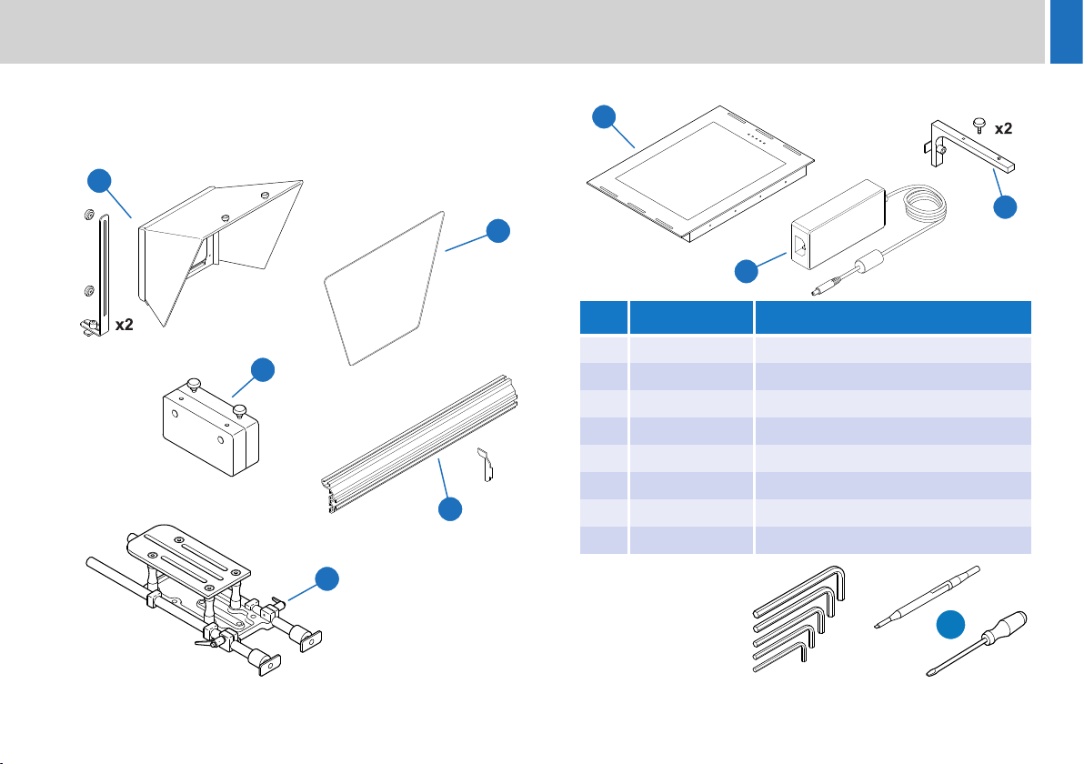
Prompter Installation Components
The following section describes the range of component parts available
for a complete prompter installation using the ELP 15 PLUS monitor.
1
2
5
x2
3
4
Box Contents
6
8
No. Part Description
1 FH-S Folding hood (unassembled)
2 RGFH-S Reflective glass panel
3 EXT-M Extrusion
4 MT-RED Camera mounting plate
5 CBMT-R Counterbalance weights
6 ELP15PLUS-M Prompter monitor
7 MT-ELP Monitor mounting brackets
8 PSU-CP 12 VDC power supply
Tools Required
• Metric Allen key set.
• Potentiometer
adjustment tool or
small screwdriver.
7
OR
5
Page 8
Components and Connections
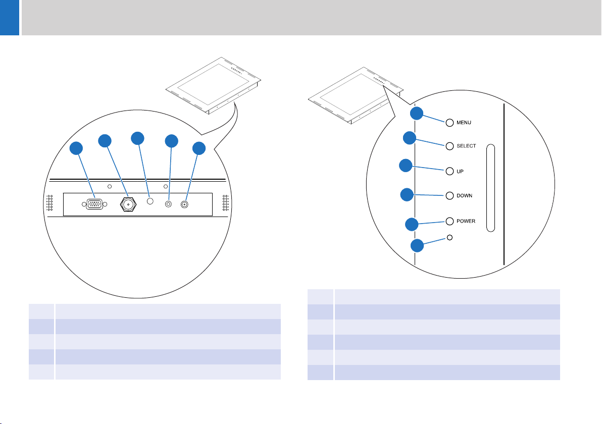
Prompter Monitor Connections
2
1
1 VGA IN socket
2 Composite video IN socket
3 Power indicator LED
4 12 VDC OUT accessory socket
5 12 VDC IN power socket
3
4
Prompter Monitor Control Panel
1
2
5
3
4
5
6
1 Menu button
2 Selection button
3 Up navigation button
4 Down navigation button
5 Power button
6 Power indicator LED
6
Page 9
Installation
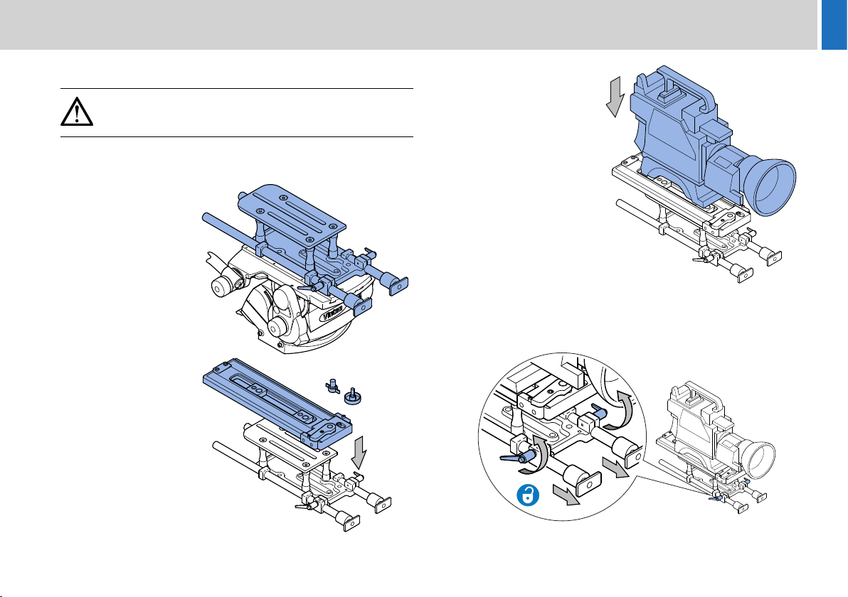
Mounting the Camera and Extrusion
WARNING! Before attempting to install or adjust the
prompter assembly, the tilt axis of the head support must be
securely locked horizontally (tilt axis).
A camera mounting plate must be fitted between the head support and
the camera body to allow installation of the prompter system.
1. Fit the MT-RED
mounting plate to the
camera support.
2. Fit the mounting plate
for the camera being
used to the top of the
MT-RED mounting
plate, using the fixing
screws provided.
3. Firmly clip the camera
into position on the
mounting plate.
4. Undo the clamps securing the telescopic rods. If necessary, slide
the rods forwards to improve access.
7
Page 10
Installation
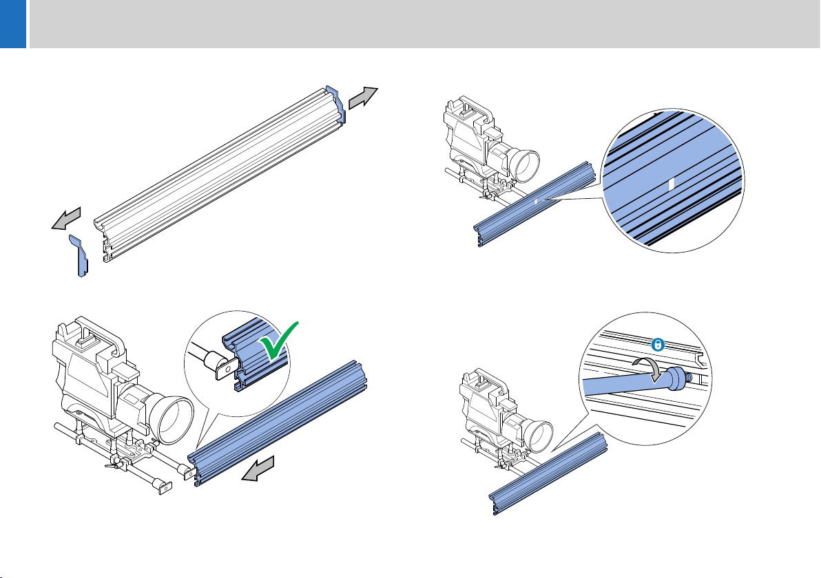
5. Remove the two protective end caps from the extrusion.
6. Slide the extrusion over the clamps on the end of the rods.
7. Centralise the extrusion, aligning the marker with the centre of the
camera lens.
8. Turn the rods to tighten the clamps onto the rear of the extrusion.
The clamps can be tightened securely by using an Allen key as a
lever through the holes in the rods.
8
Page 11
Installation
Mounting the Prompter Monitor
WARNING! Before attempting to install or adjust the
prompter monitor assembly, the tilt axis of the head support
must remain securely locked horizontally.
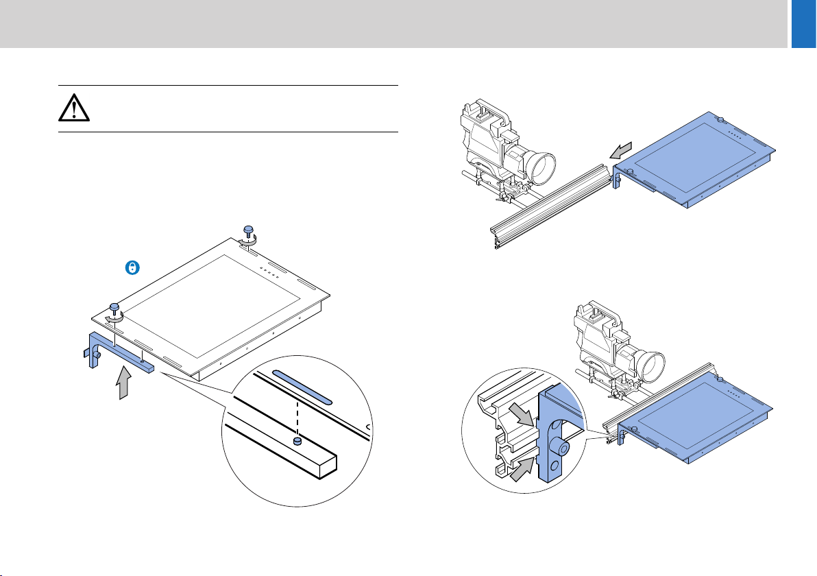
When the extrusion is fitted and correctly secured to the camera mount,
the prompter monitor can be fitted.
1. Fit the mounting brackets to the monitor. Ensure that the dowel pin
is seated in the slot on the monitor. Do not fully tighten the fixing
screws at this point.
2. Align the clamps on the monitor brackets with the slot in the front
of the extrusion and slide the assembly into position.
3. Ensure that the indents on the mounting brackets are correctly
seated on the extrusion.
9
Page 12
Installation
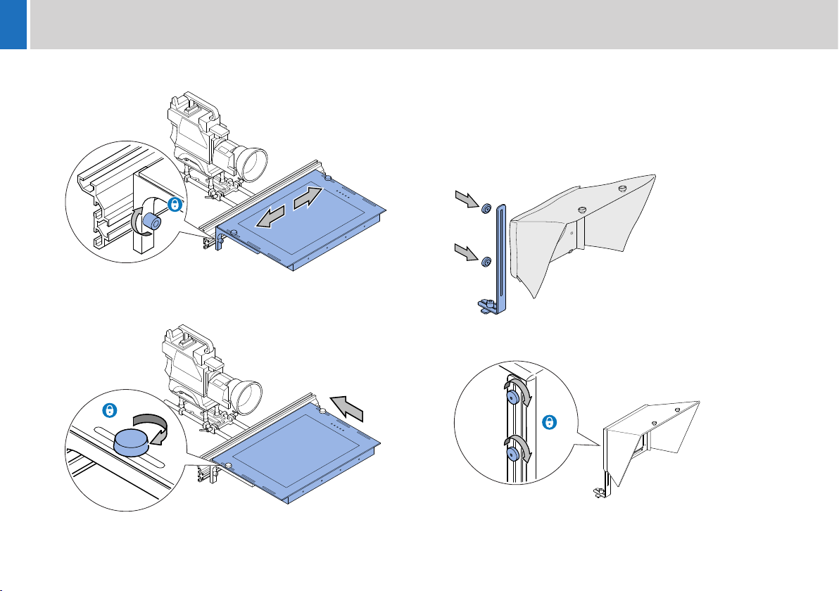
4. Centralise the monitor on the extrusion and tighten the two fixing
screws.
5. Fully push the monitor back towards the extrusion. Tighten the two
fixing screws to secure the monitor in position.
Assembling and Fitting the Hood
The standard folding hood (FH-S) is recommended for use with the
ELP15 PLUS on camera prompter. Fixing brackets are supplied for use
with the hood.
1. Align the slot in the hood bracket and the two clamping knobs with
the two threaded studs on the rear of the hood.
2. Tighten the clamping knobs to secure the hood bracket in position.
10
Page 13
Installation
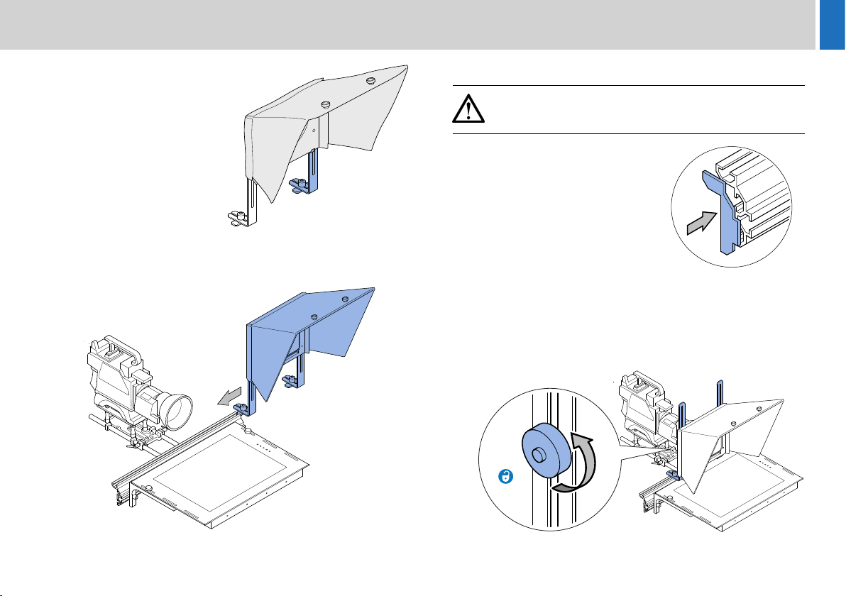
3. Repeat steps 1 and 2 for
the opposite hood bracket.
4. Align the clamps on the ends of the hood brackets with the slot in
the top of the extrusion. Slide the hood assembly onto the
extrusion.
Fitting the Extrusion End Caps
WARNING! Risk of personal injury or injury to others.
When the hood has been installed, the supplied extrusion
end caps must be fitted.
Firmly press the extrusion end caps
into place at both ends of the extrusion.
Adjusting the Hood Position
The vertical and horizontal position of the hood must be adjusted to
centralise it with the camera lens.
1. Loosen the four clamping knobs on the rear slides of the hood
mounting brackets.
11
Page 14
Installation
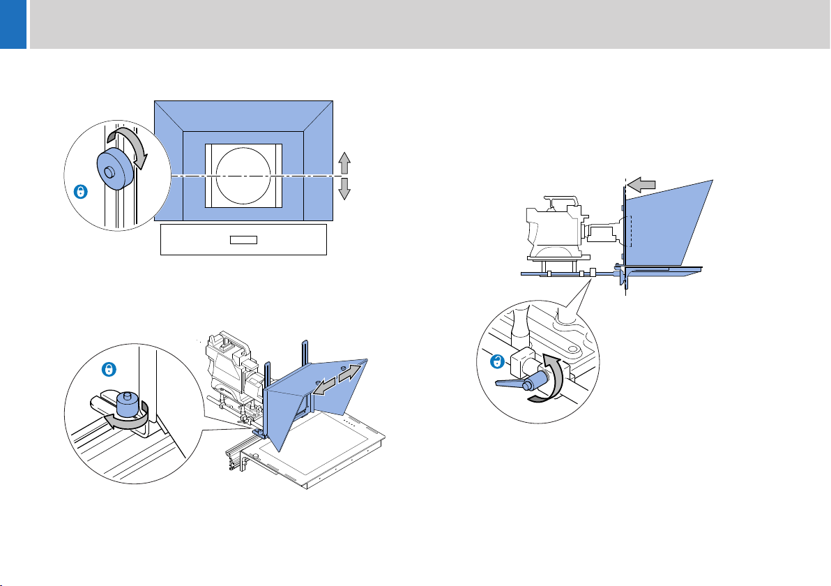
2. Adjust the vertical position of the hood on the slides to centralise it
with the camera lens and fully re-tighten the clamping knobs.
3. Adjust the horizontal position of the hood in the extrusion slot to
centralise it with the camera lens. Tighten the clamping knobs to
secure the hood in position.
Adjusting the Prompter Assembly Position
The horizontal position of the prompter assembly must be adjusted to
optimise its position relative to the camera lens.
1. Loosen the clamp handles on the MT-RED mounting plate and
move the prompter assembly back until the hood overlaps the
camera lens.
2. Re-tighten the clamp handles to secure the assembly.
12
Page 15
Installation
Fitting the Reflective Glass Panel
WARNING! Risk of personal injury or injury to others.
Care must be taken when handling and installing the
reflective glass panels. Always store spare glass panels in
the original packaging.
WARNING! Only use the correct size glass panel designed
for the installed hood.
When the hood has been installed, the reflective glass panel can be
fitted to the prompter assembly.
Panel Orientation
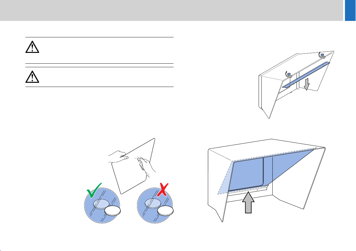
For the ELP 15 PLUS prompter to display images, it is essential that the
reflective side of the glass is installed facing outwards. The reflective
side of the glass can be established as follows:
Carefully hold a blunt
object such as a coin
against the surface of the
glass.
If the object is being held
against the reflective side,
there will be no gap (depth
of the glass) before the
reflection.
Fitting the Glass Panel
The installation procedure for the glass panel is the same on all types
of hood, although there are more fixing screws on the larger hoods.
1. Remove all the screw
fixings from the top of the
hood to release the top
glazing bar.
2. Carefully position the glass panel on the bottom glazing bar inside
the hood.
13
Page 16
Installation
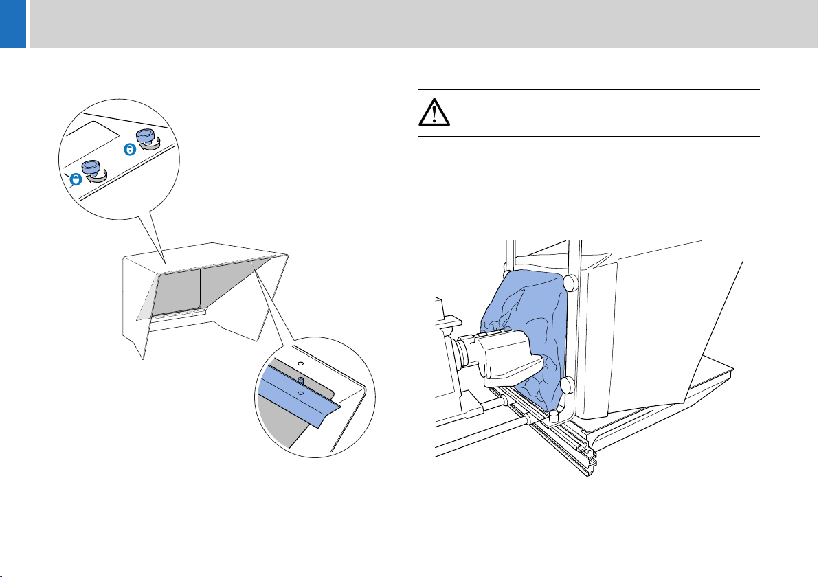
3. With the glass supported at all times, replace the top glazing bar
and secure with the screw fixings.
Fitting the Light Shield Cloth
CAUTION! Ensure that the light shield cloth is only loosely
fitted around the body of the servo lens to allow it to
continue operating freely.
The light shield cloth is built in to the hood and must be fitted around the
camera lens to prevent light entering behind the glass. This is essential
for the prompter to display text clearly.
Fit the light shield cloth around the camera lens and pull the drawstring
to fully exclude incidental light.
14
Page 17
Installation
Fitting the Counterbalance Weights
The prompter installation must have counterbalance weights fitted to
the rear of the mounting to compensate for the front-heavy effect of the
prompter monitor and hood.
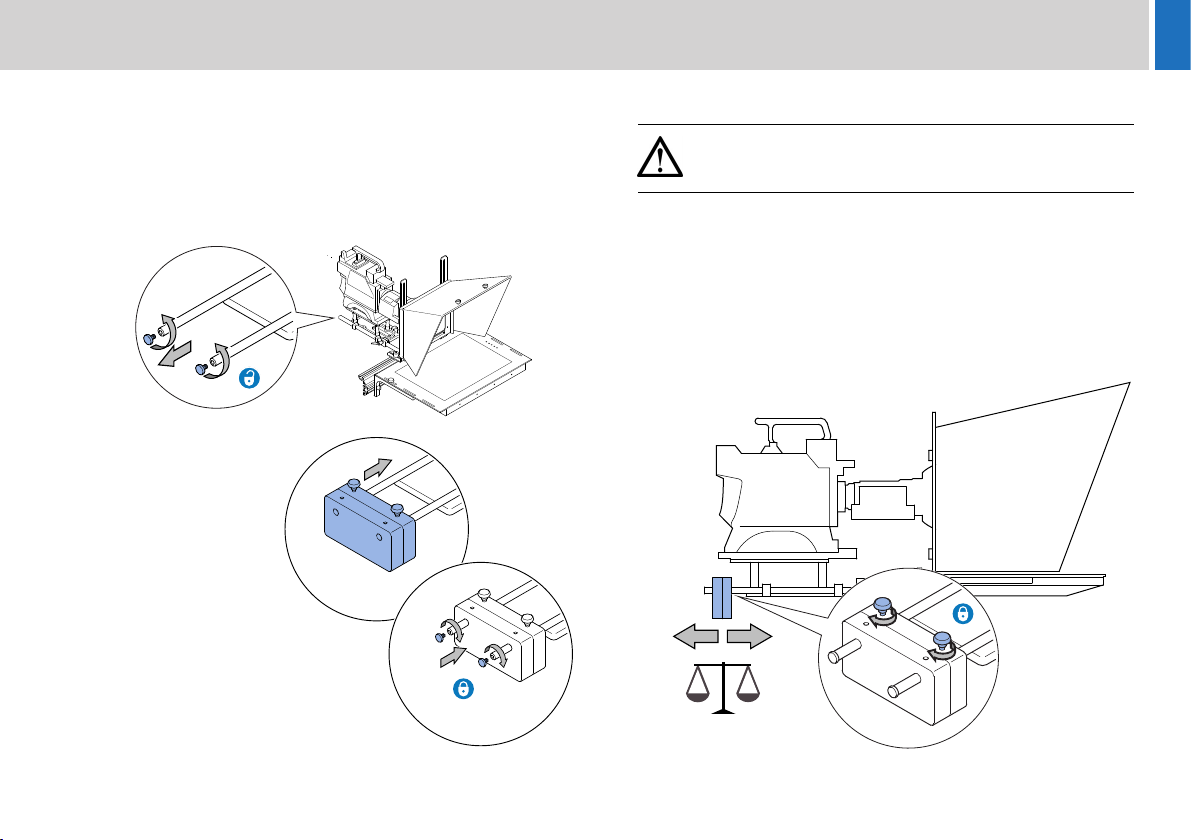
1. Unscrew the end caps from the mounting rods protruding from the
rear of the mounting plate.
2. Carefully slide the
counterbalance
weights onto the rods.
3. Refit the end caps
securely.
Balancing and Adjustments
WARNING! After fitting or adjusting the prompter assembly
and any accessories, the payload must be correctly rebalanced.
Balancing is achieved by correctly positioning the counterbalance
weights. Other adjustments can also be made to the prompter
assembly position if this is a requirement of the installation.
Basic Balancing
1.
Slide the counterbalance weights along the rods and secure in
position with the two clamping screws. Unlock the tilt axis and
check the fore and aft balance of the payload.
15
Page 18
Installation
2. If the payload is not correctly balanced, lock the tilt axis and:
a) If the payload is falling forward (front heavy), move the
counterbalance weights further back on the rods.
b) If the payload is falling backwards (rear heavy), move the
counterbalance weights further forward on the rods.
3. Secure the counterbalance weights and re-check the balance.
Splitting the Counterbalance weights
If the counterbalance weights have too much effect even in the closest
mounting position, one half can be removed.
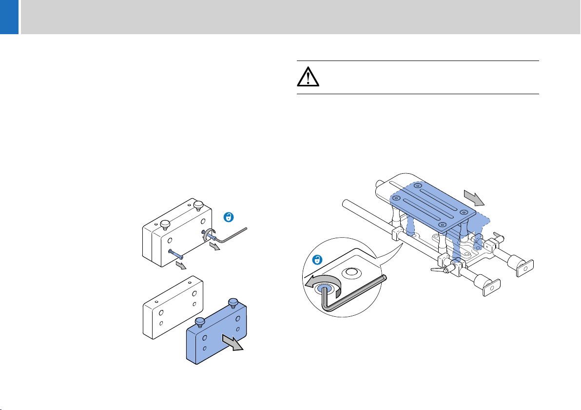
1. If fitted, remove the counterbalance weights from the prompter
assembly.
2. Using a 4 mm Allen
key, remove the two
screws securing the
weights together.
3. Separate the weights
and refit one of the
halves with the
clamping screws.
Additional Adjustments
WARNING! Before attempting to adjust the prompter
assembly, the tilt axis of the head support must be securely
locked horizontally (tilt axis).
Additional adjustments can be made to the MT-RED camera mounting
plate if balancing cannot be achieved or there are specific requirements
for an installation.
The top camera mounting plate can be moved to offset the position of
the camera, by removing the bottom screws with a 4 mm Allen key and
reseating the assembly in the other four screw holes.
16
Camera Support Adjustments
If necessary, further balancing and positional adjustments can be made
to the camera head support (manual or robotic).
Page 19
Installation
Connecting the Prompter Monitor
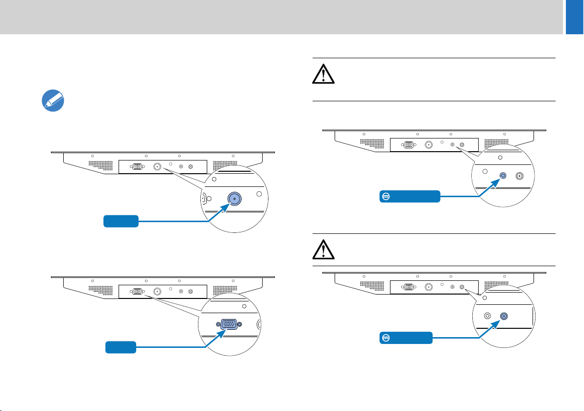
The connections panel is located at the rear of the monitor.
Video Connection
Connection using composite video or HD/SDI to the
prompter monitor must always be made with screened
75Ω coaxial cable.The video cable screen must be
connected to earth (ground) at both ends.
Composite Video Connection
Video IN
VGA Connection
This connection allows a PC VGA signal to be displayed on the monitor.
Accessory DC Connection
CAUTION! The accessory DC out socket is intended for
use with approved Autoscript accessories only. Do not
exceed the current output limit of the product when
powering auxiliary devices.
Provides a 12V DC supply to operate external accessories such as the
Autoscript +TallyPlus+.
12V DC OUT
Power Connection
CAUTION! Only use a regulated 12V DC power source
capable of supplying at least 3A.
VGA IN
12V DC IN
For more information on the specifications of the connection sockets,
see the section Connections Data on page 23.
17
Page 20
Installation
Powering Up
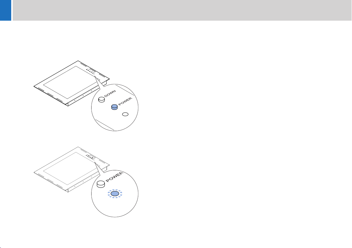
Before powering up, ensure that all external cable connections have
been secured correctly.
To power up, depress the on/off power switch.
If power is present, the power indication LED will illuminate.
18
Page 21
Configuration
Control Panel Buttons
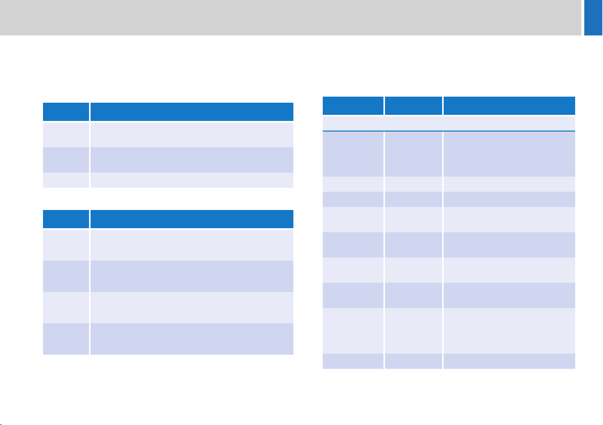
The buttons on the control panel are used to configure and operate the
prompter monitor screen.
Direct Function Buttons
Button Button Function
SELECT Video input selection - Press repeatedly until the
desired input is displayed
UP Backlight brightness control bar is selected - then use
the UP/DOWN buttons to adjust
DOWN Auto picture adjustment (RGB input only)
OSD Menu control Buttons
Button Button Function
MENU • Enters the OSD menus and sub menus
• Exits menus and sub menus
SELECT • Selects a menu page
• Selects a sub menu function
UP • Navigates up through a menu
• Adjusts a setting value
DOWN • Navigates down through a menu
• Adjusts a setting value
Monitor Function OSD Menus
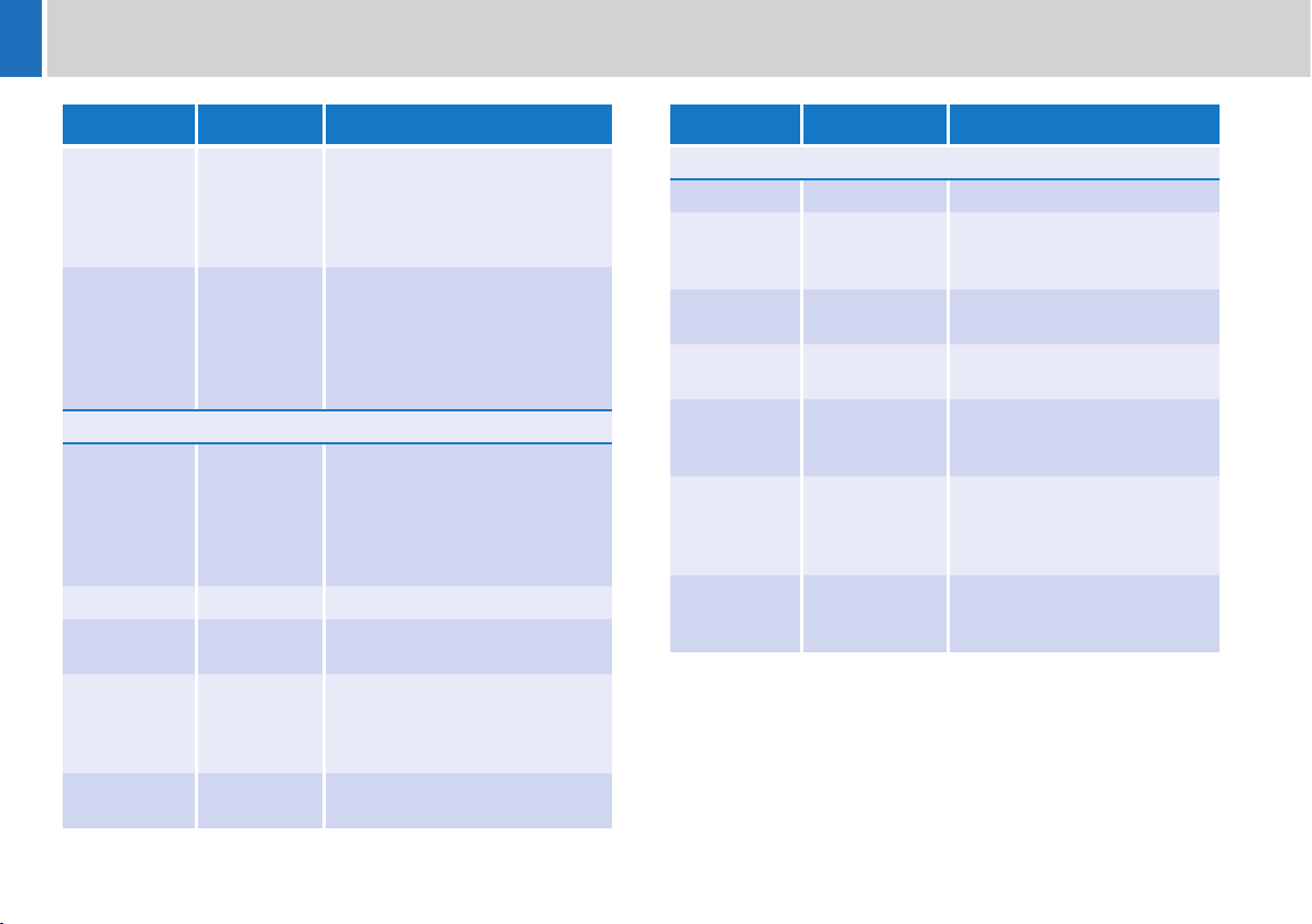
A description of the monitor function OSD setup menus is shown in the
following table, with main pages, sub menus and any parameters that
can be changed by the user.
Sub Menu Parameters Description
Main Page - PICTURE (RGB/DVI/CVBS/HDMI)
Picture Mode • Standard
• Dynamic
• Soft
• Personal
Contrast 0 - 100 Adjusts the screen contrast
Brightness 0 - 100 Adjusts the screen brightness
Backlight 0 - 100 Adjusts the brightness level of
Sharpness 0 - 100 Adjusts the sharpness of the
Tint -50 - +50 CVBS/HDMI only - Adjusts the
Color 0 - 100 CVBS/HDMI only - Adjusts the
Color Mode • Normal
• Warm
• Cool
• User(RGB)
Adjusts the preset picture mode
the monitor backlight
screen image
tint of the screen image
colour of the screen image
Adjusts the colour temperature of
the screen image
19
Page 22
Configuration
Sub Menu Parameters Description
3D NR • Standard
• Strong
• Auto
•Off
• Weak
Auto Color RGB only - Automatically adjusts
Main Page - OPTION
Menu
Language
Transparency 0 - 100% Adjusts the OSD transparency
OSD Time
Out
Source
Setting
Restore
Default
• English
• Française
• Deutsch
• Italiano
• Español
• Nederlands
• 5-60 Secs
•Off
• CVBS
• HDMI
• DVI
• RGB
• YES
•NO
Selects the desired NR mode
the horizontal and vertical
positions of the image. The
monitor screen must be
displaying prompted text or
images for this to function
Selects the OSD language
Defines the OSD time out period
when idle
Turns the input sources ON or
OFF
Resets all settings (except OSD
language) to factory defaults
Sub Menu Parameters Description
Main Page - FUNCTION
Sleep Timer 0 - 240 Min Adjusts the sleep time duration
Zoom Mode • Normal
• Wide
• Zoom*
Image Flip •On
•Off
Image Mirror •On
•Off
Auto Source •On
•Off
XGA Mode • 1024x768
• 1280x768
• 1360x768
• 1366x768
HDMI Mode •PC
• Video
• No Overscan
Selects the current zoom mode
(*Zoom selection for CVBS and
HDMI only)
Reverses the displayed image
vertically
Reverses the displayed image
horizontally
When ‘On’ this function detects
valid input sources
automatically
Selects the resolution of the
RGB input
Selects the HDMI image setting
20
Page 23
Maintenance
Routine Maintenance
The ELP15 PLUS on-camera prompter requires minimal routine
maintenance, apart from checking the connections and overall
operation periodically.
Routine checks
During use, check the following:
• Check cables for signs of wear or damage. Replace as necessary.
• Check that all cables are connected properly.
Cleaning
WARNING! Risk of electric shock. Disconnect and isolate
the product from the power supply before cleaning.
Prompter Assembly Cleaning
During normal use the only cleaning required should be a regular wipe
over with a dry, lint-free cloth. Dirt accumulated during storage or
periods of disuse may be removed with a vacuum cleaner. Particular
attention should be paid to all connection ports on the monitor.
Reflective Glass Cleaning
WARNING! Risk of personal injury or injury to others.
Care must be taken when handling or cleaning the reflective
glass panels. Always store spare glass panels in the
original packaging.
Care and cleaning of the reflective glass panel is essential for
increased life and prompting display performance.
No solvents or glass cleaners should be used. Only use clean water
and a damp lens cloth when cleaning. Do not apply excessive pressure
to the reflective glass panel during the cleaning process.
21
Page 24

Troubleshooting
Fault Check Comments
The monitor is not
powering up.
No prompting text
or video display on
the monitor screen.
The prompting text
display is ‘noisy’
(poor quality
imaging)
Check that the DC power source is connected and secured. See the section Power Connection on
Check that AC power is being supplied to the DC adaptor.
Check that the video cable is connected and the video source is active. See the section Video Connection on
Use the INPUT SELECTION button to step through to the correct video
input channel.
Ensure that quality screened cables have been used for the video signal
and that the screen is earthed at both ends.
page 17
page 17
See the section Control Panel Buttons on
page 19
22
Page 25
Technical Specification
Physical Data
Width*. . . . . . . . . . . . . . . . . . . . . . . . . . . . . . . . . . . . . 415 mm (16.3 in)
Height* . . . . . . . . . . . . . . . . . . . . . . . . . . . . . . . . . . . . 275 mm (10.8 in)
Length* . . . . . . . . . . . . . . . . . . . . . . . . . . . . . . . . . . . . . . 44 mm (1.7 in)
Weight . . . . . . . . . . . . . . . . . . . . . . . . . . . . . . . . . . . . . . 2.3 kg (5.1 lb)
*Excluding controls/connectors.
Environmental Data
Operating temperature range . . . . . . . . 5°C to +40°C (41°F to +104°F)
Storage temperature range . . . . . . . . -20°C to +60°C (-4°F to +140°F)
Electrical Data
Video inputs . . . . . . . . . . . . . . . . . . . . . . . . . . . . . . . . PAL/NTSC, VGA
DC power input. . . . . . . . . . . . . . . . . . . . . . . . . . . . . . . . . . . . . 12V DC
Power consumption . . . . . . . . . . . . . . . . . . . . . . . . . . . . . . 16W (1.3A)
Display Data
Backlight technology . . . . . . . . . . . . . . . . . . . . . . . . . . . . . . . . . . . LED
Brightness . . . . . . . . . . . . . . . . . . . . . . . . . . . . . . . . . . . . . . . . 400 nits
Contrast ratio . . . . . . . . . . . . . . . . . . . . . . . . . . . . . . . . . . . . . . . . 700:1
Resolution . . . . . . . . . . . . . . . . . . . . . . . . . . . . . . . . 1024 x 768 (XGA)
Viewing angle . . . . . . . . . . . . . . . . . . . . . . . . . . . . . . . 160°(H), 140°(V)
Diagonal screen size . . . . . . . . . . . . . . . . . . . . . . . . . . 381 mm (15 in)
Display area . . . . . . . . . . . . . . . . . . . . . . 304.1 x 228.1 mm (12 x 9 in)
Reading range . . . . . . . . . . . . . . . . . . . . . . . . . . . . . . . 5 m (16 ft, 5 in)
Connections Data
Composite Video In and Out
Connector type: 75Ω BNC socket.
Pin Signal
Centre Composite Video In (PAL or NTSC)
Outer GROUND (Cable screen)
VGA Input
Connector type: 15 pin High Density D socket.
Pin connections conform to the VESA VGA standard.
DC Power Input
Connector type: 2.1 mm power socket.
Pin Signal
Centre +12V DC
Outer GROUND
Accessory DC Output
Connector type: 3.5 mm mono jack socket.
Pin Signal
Tip +12V DC
Sleeve GROUND
Technical specifications are subject to change without notice.
23
Page 26
General Notices
FCC Certification
ELP15 Plus Prompter
ELP15PLUS-ME
FCC Notice
This product complies with the limits for a Class A digital device,
pursuant to Part 15 of the FCC Rules. These limits are designed to
provide reasonable protection against harmful interference in a
commercial environment. This equipment generates, uses and can
radiate radio frequency energy and, if not installed and used in
accordance with the instructions, may cause harmful interference with
radio communications. Operation of this product in a residential area is
likely to cause harmful interference, in which case you will be required
to correct the interference at your own expense.
FCC Warning
Changes or modifications not expressly approved by the party
responsible for compliance could void the user’s authority to operate
the equipment.
FCC Declaration of Conformity
This product complies with Part 15 of the FCC Rules. Operation is
subject to the following two conditions:
1.This product may not cause harmful interference.
2.This product must accept any interference received, including
interference that may cause undesired operations.
Declaration of Conformity
Vitec Videocom Limited declares that this product has been
manufactured in accordance with BS EN ISO 9001:2008.
This product complies with the following EU Directives:
• Low Voltage Directive 2006/95/EC
• EMC Directive 2004/108/EC
Compliance with these directives implies conformity to applicable
harmonized European standards (European Norms) which are listed on
the EU Declaration of Conformity for this product or product family. A
copy of the Declaration of Conformity is available upon request.
Environmental considerations
ROHS Compliance Statement
Vitec Videocom Limited is compliant with the European Union Directive
2002/95/EC Restrictions of Hazardous Substances (RoHS) that
restricts the use of hazardous substances in Electrical and Electronic
Equipment.
24
Page 27

European Union Waste of Electrical and Electronic
Equipment (WEEE) Directive (2002/96/EC)
This symbol marked on the product or its packaging indicates that this
product must not be disposed of with general household waste. In
some countries or European Community regions separate collection
systems have been set up to handle the recycling of electrical and
electronic waste products. By ensuring this product is disposed of
correctly, you will help prevent potentially negative consequences for
the environment and human health. The recycling of materials helps
conserve natural resources.
Visit our website for information on how to safely dispose of this product
and its packaging.
In countries outside the EU:
Dispose of this product at a collection point for the recycling of electrical
and electronic equipment according to your local government
regulations.
Pollution statement
This equipment is designed for operation in Pollution Degree 2
environments.
General Notices
25
Page 28

Page 29

Page 30

Page 31

Page 32

Publication part No. ELP15PLUS-4980/1
Autoscript
AV
itec Group brand
www.autoscript.tv
 Loading...