


Autoquip Q-LIFT User Manual
INSTALLATION, OPERATION
AND SERVICE MANUAL
Q- LIFT
P.O. Box 1058 • 1058 West Industrial Avenue • Guthrie, OK 73044-1058 • 888-811-9876
405-282-5200 • FAX: 405-282-3302 • www.autoquip.com
Item #830QL Version 2.0
1
10/2011

1. Introduction And Warranty...............................................................................................................................3
1.1 Introduction......................................................................................................................................................3
1.1.1 Identification................................................................................................................................................3
1.1.2 Inspection....................................................................................................................................................3
1.1.3 Planned Maintenance Program ..................................................................................................................3
1.2 Responsibility Of Owners/Users......................................................................................................................3
1.2.1 Deflection....................................................................................................................................................3
1.2.2 Inspection & Maintenance...........................................................................................................................4
1.2.3 Removal From Service ...............................................................................................................................4
1.2.4 Repairs........................................................................................................................................................4
1.2.5 Operators....................................................................................................................................................4
1.2.6 Before Operation.........................................................................................................................................4
1.2.7 During Operation.........................................................................................................................................4
1.2.8 Modifications Or Alterations........................................................................................................................4
1.3 Warranty..........................................................................................................................................................5
2. Specifications ....................................................................................................................................................6
2.1 Q-Lift Models...................................................................................................................................................6
2.2 Lift Specifications ............................................................................................................................................6
2.3 Load Capacity..................................................................................................................................................6
2.4 Unbalanced Loading .......................................................................................................................................6
2.5 Pump Pressure................................................................................................................................................7
2.6 Lift Duty ...........................................................................................................................................................7
3. Safety..................................................................................................................................................................8
3.1 Safety Signal Words........................................................................................................................................8
3.2 Installation .......................................................................................................................................................8
3.3 Operation.........................................................................................................................................................9
3.4 Hydraulics........................................................................................................................................................9
3.5 Maintenance..................................................................................................................................................10
3.6 Modifications..................................................................................................................................................11
3.7 Labels............................................................................................................................................................11
4. Installation........................................................................................................................................................14
4.1 Pit Installation................................................................................................................................................14
4.2 Shimming And Anchoring Lift To Concrete...................................................................................................17
4.3 Remote Power Unit Installation.....................................................................................................................17
4.4 Power Unit Wiring..........................................................................................................................................17
4.4.1 Intermittent Remote Power Unit................................................................................................................17
4.4.2 Heavy Duty Remote Power Unit...............................................................................................................18
4.5 Accordion Skirt Installation............................................................................................................................18
5. Operation..........................................................................................................................................................20
5.1 Raise And Lower Lift.....................................................................................................................................20
6. Maintenance.....................................................................................................................................................21
6.1 Maintenance Devices....................................................................................................................................21
6.2 Routine Maintenance ....................................................................................................................................23
6.2.1 Every Day Or 10 Hours Of Operation.......................................................................................................23
6.2.2 Every Month Or 100 Hours Of Operation..................................................................................................24
6.2.3 Every Year Or 1000 Hours Of Operation..................................................................................................24
6.2.4 Oil Requirements ......................................................................................................................................24
6.2.5 Oil Capacity...............................................................................................................................................25
6.3 General Maintenance....................................................................................................................................25
6.3.1 Hydraulic Cylinder Repair.........................................................................................................................25
6.3.2 Bleeding Air From System........................................................................................................................27
6.3.3 Hydraulic Velocity Fuse (HVF) Replacement ...........................................................................................27
6.3.4 Hose Orientation.......................................................................................................................................28
6.3.5 Up Stop Valve Adjustment........................................................................................................................28
7. Troubleshooting ..............................................................................................................................................40
8. Parts Lists.........................................................................................................................................................44
2

1. INTRODUCTION AND WARRANTY
1.1 Introduction
Please read and understand this manual prior to installation or operation of this lift. Failure to do so
could lead to property damage and/or serious personal injury. If you have any questions, call a local
dealer or Autoquip Corporation at 1-888-811-9876 or 405-282-5200.
Please record the following information and refer to it when calling your dealer or Autoquip.
Model Number:________________Serial Number: ___________________
Installation Date _____/_____/_____
1.1.1 Identification
When ordering parts or requesting information or service on this lift, PLEASE REFER TO THE MODEL
AND SERIAL NUMBER. This information is on a nameplate attached to the leg assembly.
Replacement parts are available from a local Autoquip distributor.
1.1.2 Inspection
Upon receipt of lift, perform a visual inspection to determine that lift not been damaged in transit. Any
damage found must be noted on delivery receipt. In addition to this preliminary inspection, carefully
inspect lift for concealed damage. Any concealed damage found that was not noted on delivery receipt
must be reported in writing to the delivering carrier within 48 hours.
Use the following checklist for inspection of lift:
1. Examine entire unit for any signs of mishandling. Carefully check power unit and push buttons.
2. Thoroughly examine all connections, making sure they have not vibrated loose during transit, and
inspect wiring for any signs of damage.
3. After installation, raise lift and inspect base frame, platform, scissors assembly, and cylinder
plumbing connections.
1.1.3 Planned Maintenance Program
A local Autoquip representative provides a Planned Maintenance Program (PMP) for this equipment
using factory-trained personnel. Call a local representative or Autoquip Corporation at 1-888-811-9876
or 405-282-5200 for more information.
1.2 Responsibility Of Owners/Users
1.2.1 Deflection
It is the responsibility of user/purchaser to advise manufacturer where deflection may be critical to the
application.
3

1.2.2 Inspection & Maintenance
Lift must be inspected and maintained in accordance with Autoquip’s operating/maintenance (O&M)
manual and with other applicable safe operating practices.
1.2.3 Removal From Service
Any lift not in safe operating condition such as, but not limited to, excessive leakage, missing parts or
fasteners, any bent or cracked structural members, cut or frayed electric, hydraulic, or pneumatic lines,
damaged or malfunctioning controls or safety devices, etc. shall be removed from service until it is
repaired to the original manufacturer’s standards.
1.2.4 Repairs
All repairs must be made by a qualified technician in conformance with Autoquip’s instructions.
1.2.5 Operators
Only trained personnel and authorized personnel shall be permitted to operate lift.
1.2.6 Before Operation
Before using lift, operator must:
• Read and/or had explained, and understood, manufacturer’s operating instructions and safety
rules.
• Inspect lift for proper operation and condition. Any suspect item must be carefully examined
and a determination made by a qualified person as to whether it constitutes a hazard. All items
not in conformance with Autoquip’s specification must be corrected before operating lift.
1.2.7 During Operation
Use lift in accordance with Autoquip’s O&M manual.
• Do not overload lift.
• Verify all safety devices are operational and in place.
• Autoquip warrants this lift for 60,000 cycles each warranty year. This number of cycles
represents normal, single shift duty. Exceeding this number of cycles shortens life of lift and
length of your warranty.
1.2.8 Modifications Or Alterations
Modifications or alterations to this equipment may be made only with written permission of Autoquip.
Unauthorized modification or alteration will void warranty.
4
1.3 Warranty
The user is solely responsible for using this equipment in a safe manner and observing all of the safety
guidelines provided in the Owner’s Manual and on the warning labels provided with the lift. If you are
unable to locate either the manual or the warning labels, please contact Autoquip or access
www.autoquip.com
Autoquip Corporation expressly warrants that this product will be free from defects in material and
workmanship under normal, intended use for a period of Two (2) Years for Labor and all electrical,
mechanical, and hydraulic components, parts or devices, and warrants the structure of the lift against
breakage or failure for a period of Five (5) years. The warranty period begins from the date of
shipment. When making a claim, immediately send your dealer or Autoquip notice of your claim. All
claims must be received by Autoquip within the warranty time period. The maximum liability of
Autoquip, under this Limited Warranty, is limited to the replacement of the equipment.
This warranty shall not apply to any Autoquip lift or parts of Autoquip lift that have been damaged or
broken in transit/shipping, or due directly or indirectly to misuse, abuse, vehicle impact, negligence,
faulty installation, fire, floods, acts of God, accidents, or that have been used in a manner contrary to
the manufacturer’s limitations or recommendations as stated in the manual, or that have been
repaired, altered or modified in any manner outside of Autoquip Corp’s manufacturing facility or which
have not been expressly authorized by Autoquip.
Autoquip Corporation makes no warranty or representation with respect to the compliance of any
equipment with state or local safety or product standard codes, and any failure to comply with such
codes shall not be considered a defect of material or workmanship under this warranty. Autoquip
Corporation shall not be liable for any direct or consequential damages resulting from such
noncompliance.
Autoquip Corporation’s obligation under this warranty is limited to the replacement or repair of
defective components at its factory or another location at Autoquip Corp’s discretion at no cost to the
owner. This is owner’s sole remedy. Replacement parts (with exception of electrical components) will
be warranted for a period of ninety (90) days. Except as stated herein, Autoquip Corporation will not be
liable for any loss, injury, or damage to persons or property, nor for direct, indirect, or consequential
damage of any kind, resulting from failure or defective operation of said equipment. All parts used to
replace defective material must be genuine Autoquip parts in order to be covered by this Limited
Warranty.
for replacement downloads or information.
AUTOQUIP CORP
P.O. Box 1058, Guthrie, OK 73044-1058
Telephone: (888) 811-9876 · (405) 282-5200
Fax: (405) 282-3302
www.autoquip.com
5

2.1 Q-Lift Models
2. SPECIFICATIONS
Model Cap.
(Lbs.)
54Q15 1500 54 61 30 x 42 1500 30 x 42 48 x 72 16 1 935
54Q35 3500 54 61 30 x 42 2000 30 x 42 48 x 66 31 2 1000
54Q50 5000 54 61 36 x 42 2500 36 x 42 48 x 60 44 3 1100
65Q12 1200 65 72 30 x 50 1200 30 x 50 48 x 78 16 1 1000
65Q25 2500 65 72 30 x 50 1500 30 x 50 48 x 78 31 2 1075
65Q40 4000 65 72 36 x 50 2000 36 x 50 48 x 72 44 3 1190
74Q10 1000 74 81 30 x 56 1000 36 x 56 48 x 84 16 1 1050
74Q20 2000 74 81 30 x 56 1500 30 x 56 48 x 78 31 2 1125
74Q35 3500 74 81 36 x 56 2000 36 x 56 48 x 72 44 3 1240
Travel
(In.)
Raised
Height
(In.)
Base
Frame
(In.)
Max
End Or
Side
Load
(Lbs.)
Std Min
Platfor
m (In.)
Max.
Platform
(Optional
Extra In.)
Raise
Time
(sec)
No
of
Cyl
2.2 Lift Specifications
Ship
Wt.
(Lbs.)
Only standard models are shown in the specification table, there are many custom designs whose
specifications may vary from these. Please consult the specific General Arrangement (GA) Drawing to
obtain the specifications for application-specific designs.
2.3 Load Capacity
Load capacity rating is stamped on a metal plate attached to lift. This figure is a net capacity rating for
a lift furnished with a standard platform. If optional items are installed on lift after leaving manufacturer,
deduct weight of these from load rating to obtain net capacity.
Do not exceed rated capacity of lift. Loading lift beyond its rated capacity is unsafe, will shorten
operational life of lift, and will void warranty.
2.4 Unbalanced Loading
The stabilization provided is basically for balanced loads. If special attachments extend beyond the
length and/or width dimensions of platform, end and/or side load capacity is reduced 2% for each oneinch extension from center. If load is rolling onto platform (in any but fully-lowered position) end and/or
side load capacity is reduced by dividing the rated end/side load by 1.50 to establish an available
“axle” load.
6

2.5 Pump Pressure
This lift incorporates a unique, positive displacement pump. Therefore, standard factory models of
same manufacture cannot replace it.
Pump can operate efficiently at intermittent pressures up to 3200 PSI and continuous duty to 2500
PSI. Factory installed safety relief valve in pump is factory-set to stay within parameters of pump and
lift requirements.
2.6 Lift Duty
Autoquip standard lifts typically include intermittent duty motors and are designed to “cycle” (one
complete “up” and one complete “down” lift operation) no more frequently than every two minutes – or
approximately 60,000 times (cycles) per year. This is considered “normal” duty.
It is the responsibility of the user to notify Autoquip whenever a specific application is likely to demand
“above normal” duty from lift. Above normal duty typically requires supplemental design features to
enhance serviceable life of lift and to avoid loss of warranty.
7
3. SAFETY
3.1 Safety Signal Words
This Owner’s Manual covers Q-Lift models produced by Autoquip. Before installing, operating or
servicing lift, you must read, understand and follow the instructions and safety warnings in this manual.
Your lift may not be equipped with some optional equipment shown in this manual.
The safety information in this manual is denoted by the safety alert symbol:
The level of risk is indicated by the following signal words.
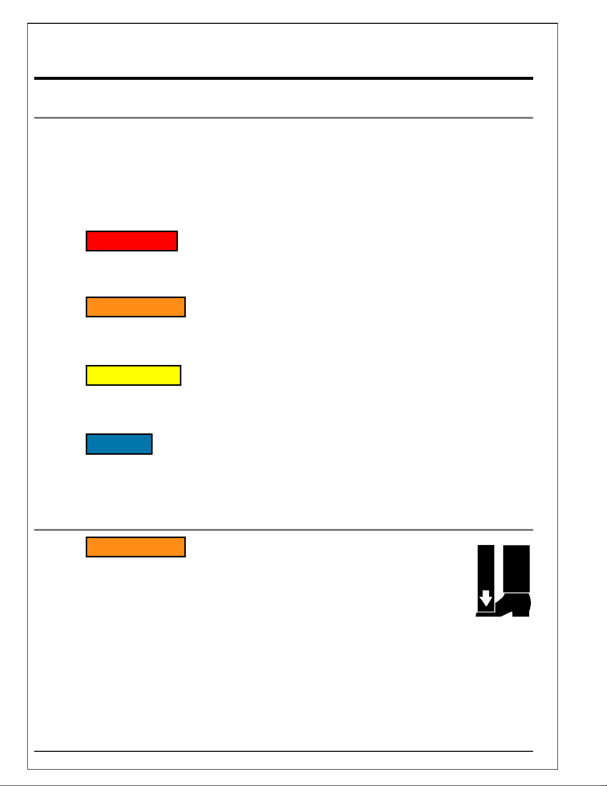
^ DANGER
DANGER – Indicates a hazardous situation, which, if not avoided, will
result in death or serious injury.
^ WARNING
WARNING – Indicates a hazardous situation, which, if not avoided, could
result in death or serious injury.
^ CAUTION
CAUTION – Indicates a hazardous situation, which, if not avoided, could
result in minor or moderate injury.
NOTICE
NOTICE – Indicates a situation that could result in damage to the lift or
other property.
^
3.2 Installation
^ WARNING
Do not install lift in a pit unless pit has a bevel toe guard or
other approved toe protection. A shear point can exist which
can cause severe foot injury.
Lift platforms traveling below floor levels may create a toe hazard as load
passes top edge of pit. This may require guarding in accordance with
Federal Regulations. Guarding must be installed prior to operating lift.
8

^ WARNING
Prevent serious injury or death.
Depending on model, weight of lift ranges from 1500 – 4450 lbs.
Use a properly rated lifting device to move and install lift.
3.3 Operation
^ WARNING
Prevent serious injury or death.
Scissor lifts are designed for a specific load and application. Do not
change load or application from original design.
Overloading, or uneven loading, could result in load instability and cause
serious personal injury.
Stay clear of lift while lift is in motion.
Never stand, sit or ride on lift.
^ WARNING
Prevent serious injury or death.
Lifts which travel to an elevation above floor level where distance between
floor and the underside of lift platform exceeds 60" must have the
scissors mechanism guarded per ANSI MH29.1.
3.4 Hydraulics
Fluids can be hazardous. Before servicing lift, check Material Safety Data Sheet (MSDS) to
understand the product, safe handling procedures, and first aid measures relating to product. Follow
this information when servicing or repairing lift.
Do not drain or pour any fluids or lubricants into ground. Check with local environmental agencies,
recycling centers, or your Autoquip dealer for correct disposal information.
^ CAUTION
Any time velocity fuses have been tripped, investigate cause of trip and
verify necessary corrective actions have been taken prior to operation of
lift.
9
^ WARNING
Prevent serious injury or death.
Do not attempt to remove Hydraulic Velocity Fuse (HVF) until maintenance
device securely supports lift and all hydraulic pressure has been relieved.
HVF is attached to elbow fitting in pressure port of cylinder. Do not use a
swivel fitting between HVF and cylinder. If HVF is installed improperly, it
will not lock up in event of a hydraulic line failure.
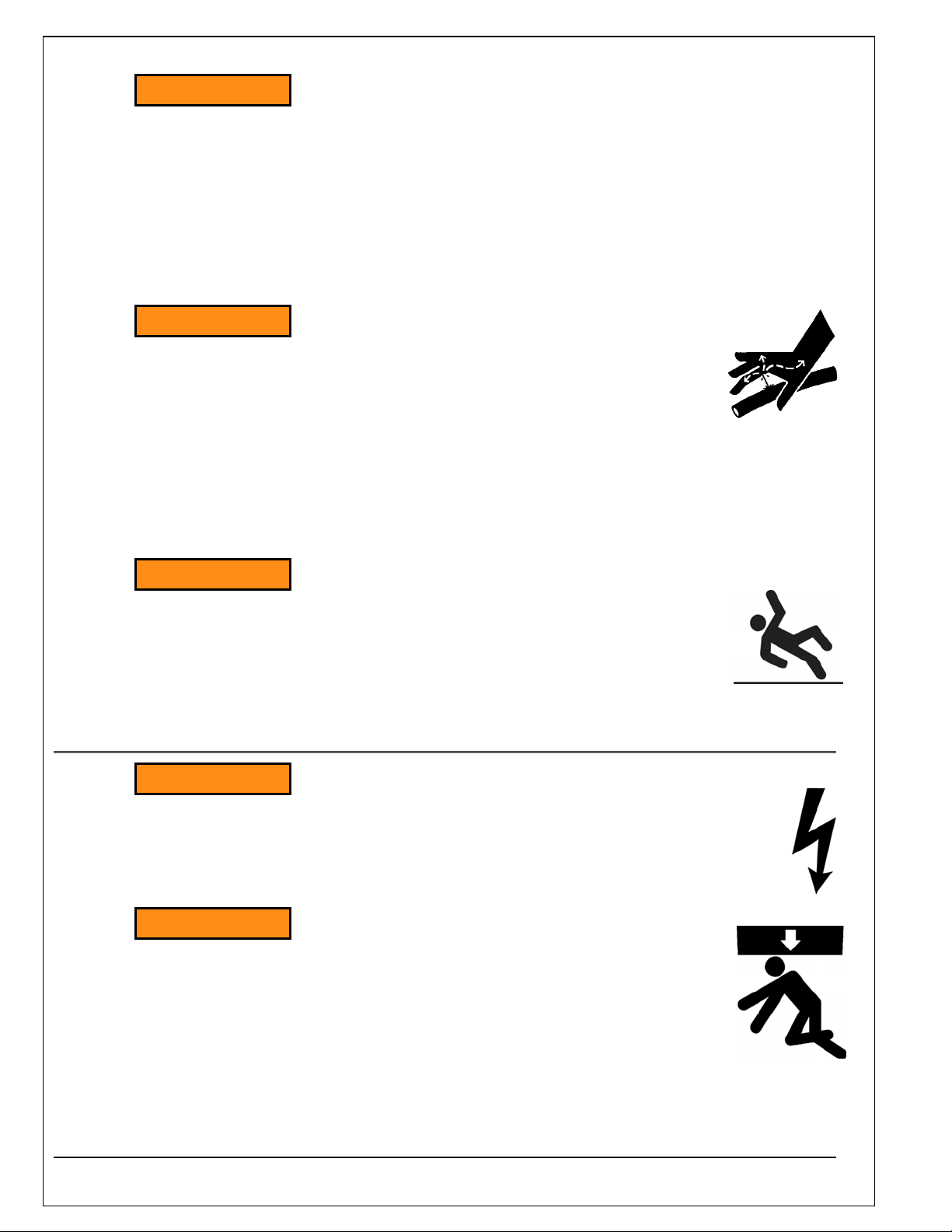
^ WARNING
Pressurized fluids can penetrate the skin.
Hydraulic hoses can fail from age, damage and exposure.
Do not search for hydraulic leaks without body and face protection. A tiny,
almost invisible leak can penetrate the skin, thereby requiring immediate
medical attention.
Use wood or cardboard to detect hydraulic leaks, never your hands.
^ WARNING
Spilled fluids and lubricants may be slippery and may also
present a fire hazard.
Clean up spilled fluids and lubricants.
3.5 Maintenance
^ WARNING
Prevent serious injury or death.
Disconnect and/or lock out electrical supply to power unit prior to any
maintenance being performed.
^ WARNING
Prevent serious injury or death.
Never go under lift platform until load is removed and scissors
mechanism is securely blocked in raised position with
maintenance devices.
10
3.6 Modifications
^ WARNING
Prevent serious injury or death.
Do not modify lift. Autoquip cannot foresee and is not responsible for
injury or damage which results from unauthorized modifications or
misuse of lift.
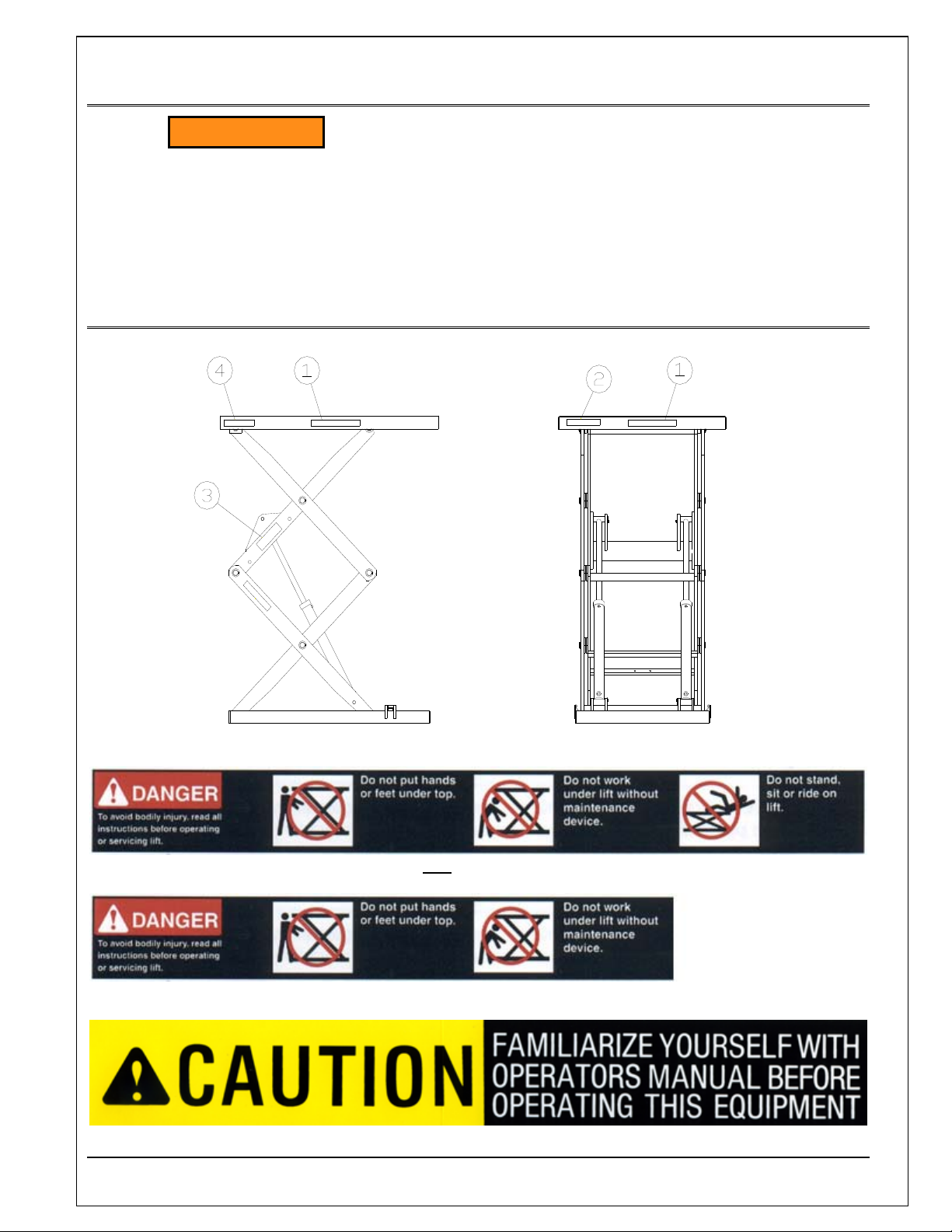
3.7 Labels
1 – 36430050 If Not
1 – 36430050M If Equipped With Handrails, Cut As Shown
Equipped With Handrails
2 – 36401487
11
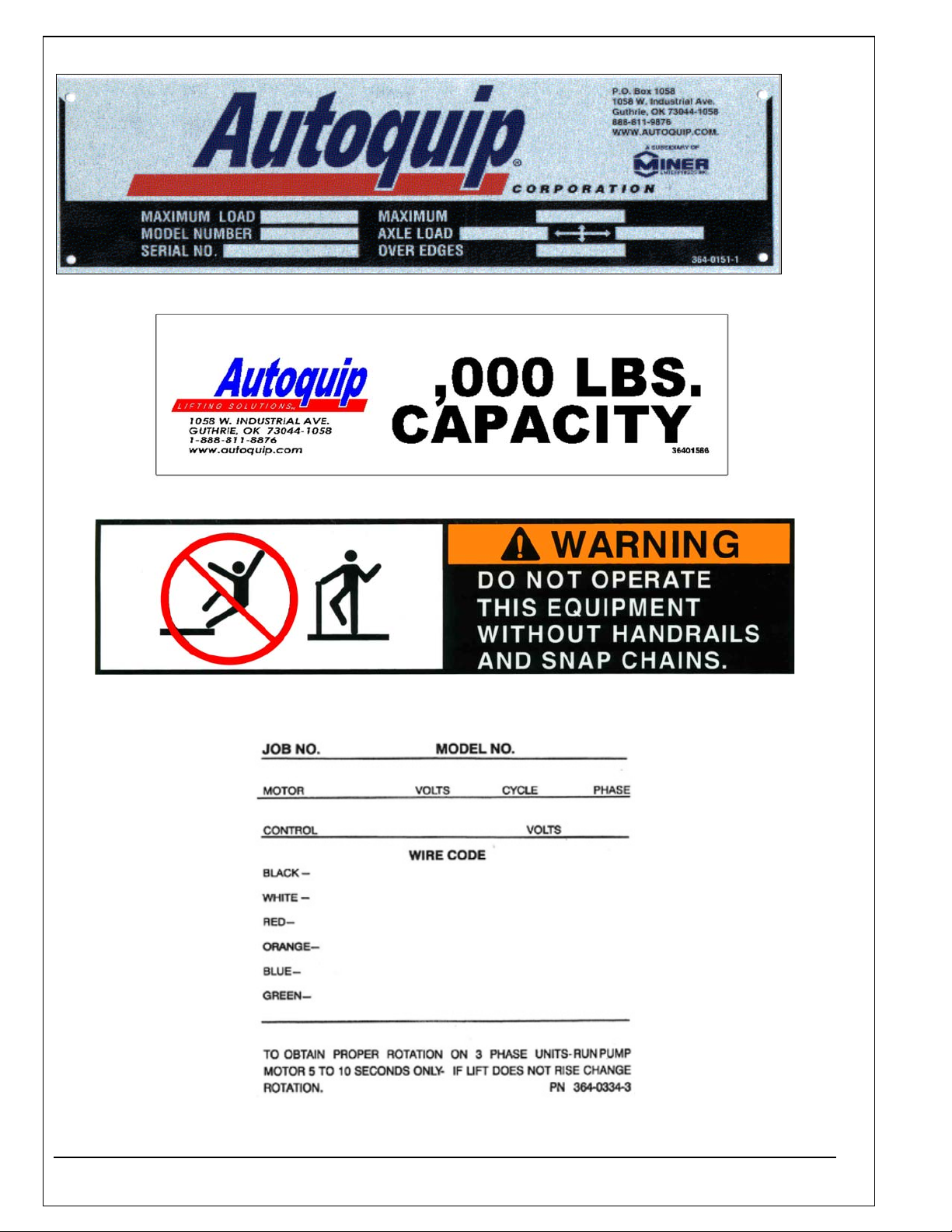
3 – 36401511
4 – 36401586
N/S – 36403715 If Equipped With Handrails
N/S – 36403343
12

^ WARNING
To protect against death or serious injury, all labels must be on lift and
must be legible.
If any of these labels are missing or cannot be read, call Autoquip for
replacement labels.
13
4.1 Pit Installation
4. INSTALLATION
^ WARNING
Do not install lift in a pit unless pit has a bevel toe guard or
other approved toe protection. A shear point may exist which
can cause severe foot injury.
Lift platforms traveling below floor levels may create a toe hazard as load
passes top edge of pit. This may require guarding in accordance with
Federal Regulations. Guarding must be installed prior to operating lift.
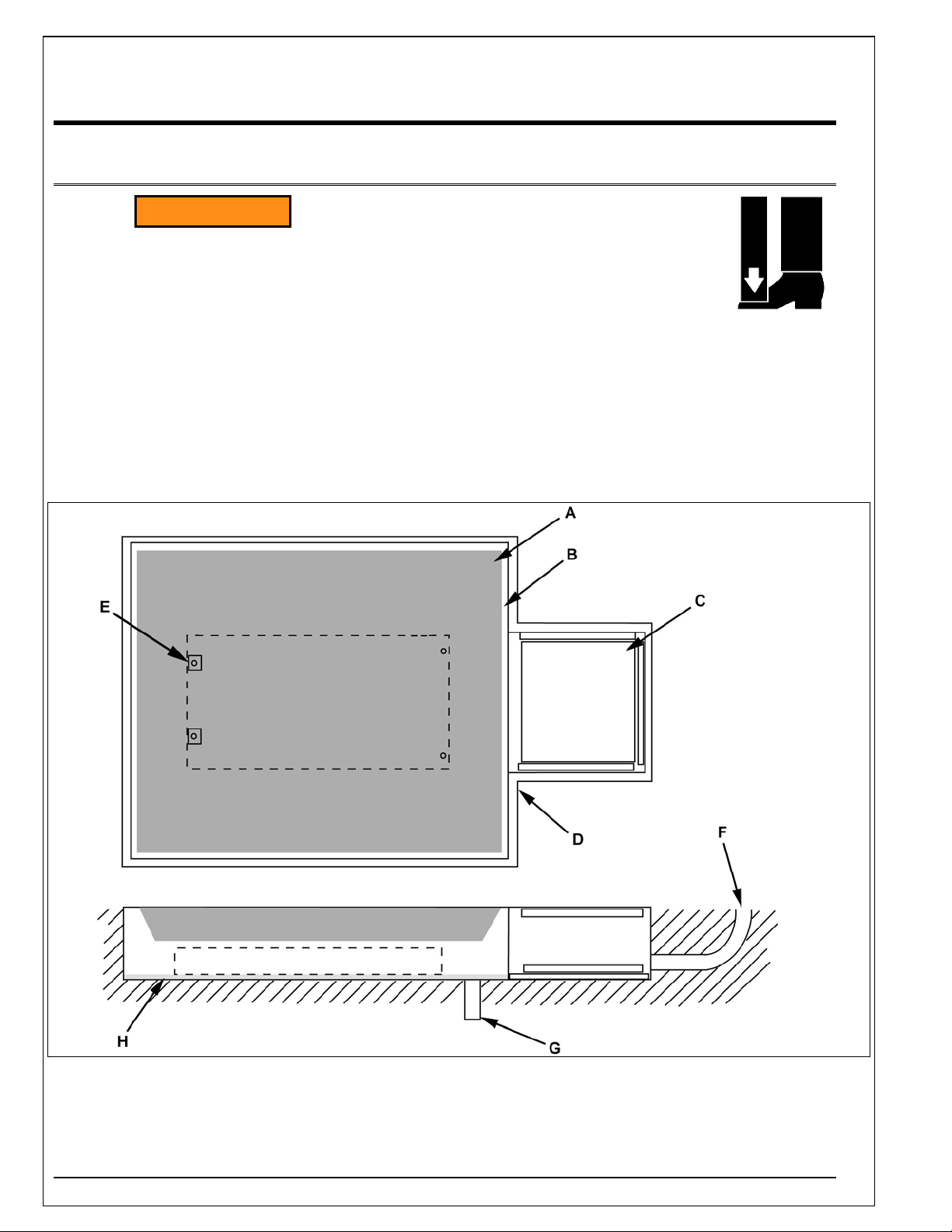
1. Check pit dimensions. Pit must be 2" longer and 2” wider tha n lift platform to allow a 1” gap between
platform and pit. Pit depth should allow ½” for shims or grout.
2. Conduit (F) diameter must be a minimum of 2".
A – Lift Platform E – Lift Anchor Points (4)
B – 1” Gap Between Deck And Pit Wall F – 2” Min. Conduit, Cust. Inst.
C – Pit Access Hatch, Optional, Installed By Customer G – Suitable Pit Drain, Cust Inst.
D – Pit Curb Angle, Suggested Min. L2” x 2” x ¼”, Cust. Inst. H – ½” Grout Under Base
14
3. Verify installation area is clean before starting. Check mounting surface of pit floor with a level or
straight edge. If floor is not level, add shims or grout under entire perimeter of base to achieve a
level and flat base installation. A level base is essential for proper wheel tracking and smooth lift
operation.
^ WARNING
Prevent serious injury or death.
Depending on model, weight of lift ranges from 1000 – 5000 lbs.
Use a properly rated lifting device to move and install lift.
4. Lower lift into pit and check for proper height. Lift must be solid and flush with pit angle framing (D).
If needed, shim to desired height. DO NOT “spot” shim. Shim along full length of frame. This will
prevent frame from sagging under load.
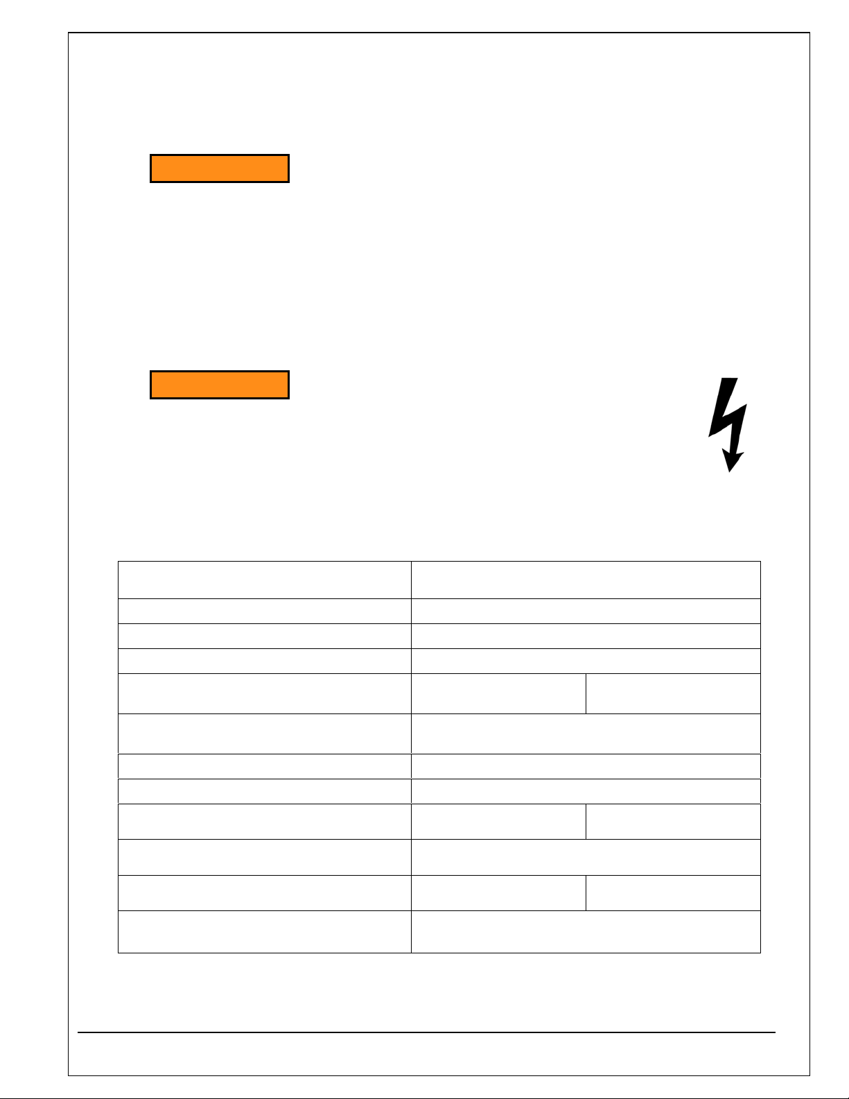
^ WARNING
Prevent serious injury or death.
Electrical service installation must be performed by a licensed
electrician and conform to all local and national electrical codes.
NOTE: For larger horsepower motors, consult factory.
HP and Voltage Full Load Amperages
1/2 HP: 115 V /60 CY/1 PH (36S15)
3/4 HP: 115 V /60 CY/1 PH
3/4 HP: 230 V /60 CY/1 PH
3 HP: 115 / 208 / 230V /60 CY/1PH
Heavy Duty Motor (Not Intermittent)
5 HP: 230 V /60 CY/1 PH
Heavy Duty Motor (Not Intermittent)
1-1/2 HP: 208 / 230 V /60 CY/3 PH
1-1/2 HP: 460 V /60 CY/ 3 PH
5 HP: 208 / 230 V /60 CY/3 PH
Intermittent Duty Motor
5 HP: 460 V /60 CY/3 PH
Intermittent Duty Motor
5 HP: 208 / 230 V /60 CY/3 PH
Heavy Duty Motor
5 HP: 460 V /60 CY/3 PH
Heavy Duty Motor
115 Volts = 15.0 Amps
115 Volts = 16.6 Amps
230 Volts = 8.3 Amps
115 V = 33.6 Amps
230 Volts = 23.0 Amps
208 / 230 V= 5.3 Amps
460Volts = 2.85 Amps
208 V=15.8 Amps 230 V=14.8 Amps
460 Volts = 7.4 Amps
208 V=16 Amps 230 V=15.2 Amps
460 V=7.6 Amps
208/230V=16.8
Amps
15