

Autoquip PLD DOCK LIFT User Manual
INSTALLATION, OPERATION
AND SERVICE MANUAL
PLD SCISSORS LIFT
P.O. Box 1058 • 1058 West Industrial Avenue • Guthrie, OK 73044-1058 • 405-282-
5200 • FAX: 405-282-8105 • www.autoquip.com
Item # 830PLD Version 1.0
09/2001

TABLE OF CONTENTS
Identification and Inspection 3
Dangers, Warnings, and Cautions 4
Label Identification 8
Specifications 11
Lift Blocking Instructions 12
Installation Instructions 14
Operating Instructions 18
Routine Maintenance 19
General Maintenance 21
Replacement Parts List 33
Troubleshooting Analysis 35
IMPORTANT
Please read and understand this manual prior to installation or operation of this lift.
Failure to do so could lead to property damage and/or serious personal injury. If
questions arise, call a local representative or Autoquip Corporation at 1-888-811-9876
or 405-282-5200.
PLANNED MAINTENANCE PROGRAM
A local Autoquip representative provides a Planned Maintenance Program (PMP) for
this equipment using factory-trained personnel. Call a local representative or Autoquip
Corporation at 1-888-811-9876 or 405-282-5200 for more information.
2

IDENTIFICATION & INSPECTION
IDENTIFICATION
When ordering parts or requesting information or service on this lift, PLEASE REFER
TO THE MODEL AND SERIAL NUMBER. This information is on a nameplate attached
to the leg assembly. Replacement parts are available from a local Autoquip distributor.
INSPECTION
Immediately upon receipt of the lift, a visual inspection should be made to determine
that the lift has not been damaged in transit. Any damage found must be noted on the
delivery receipt. In addition to this preliminary inspection, the lift should be carefully
inspected for concealed damage. Any concealed damage found that was not noted on
the delivery receipt should be reported in writing to the delivering carrier within 48 hours.
The following is a checklist that will aid in the inspection of the lift.
1. Examine entire unit for any signs of mishandling. Pay special attention to the power
unit and controls.
2. Thoroughly examine all connections, making sure they have not vibrated loose
during transit.
3. After installation, raise the lift and inspect the base frame and scissors assembly.
3
DANGERS, WARNINGS & CAUTIONS
SAFETY ALERTS (Required Reading!)
The following SAFETY ALERTS are intended to create awareness of owners,
operators, and maintenance personnel of the potential safety hazards and the steps that
must be taken to avoid accidents. These same alerts are inserted throughout this
manual to identify specific hazards that may endanger uninformed personnel.
Identification of every conceivable hazardous situation is impossible. Therefore, all
personnel have the responsibility to diligently exercise safe practices whenever exposed
to this equipment.
____________________________________________________________
DANGER!
Identifies a hazardous situation that presents the imminent probability of
death or of severe personal injury!!
_____________________________________________________________
WARNING!
Identifies a hazardous situation that has the potential of causing death or
serious personal injury.
CAUTION!
Identifies a hazardous situation that could lead to the possibility of personal
injury of death, and/or may result in equipment damage.
_____________________________________________________________
4
DANGERS, WARNINGS & CAUTIONS
Read and understand this manual and all labels prior to operating or servicing the
lift. All labels are provided in accordance with ANSI Z535.4.
DANGER!
Do not work under lift without maintenance device! To avoid personal
injury, NEVER go under the lift platform until the load is removed and the
scissors mechanism is securely blocked in the open position. See "Lift
Blocking Instructions" section.
DANGER!
To avoid personal injury, stand clear of scissors leg mechanism while lift is
in motion.
DANGER!
HIGH VOLTAGE!! Disconnect and/or lock out the electrical supply to the
power unit prior to any maintenance being performed.
DANGER!
Extending the platform length or width beyond the factory limit could cause
the unit to tip, which could result in personal injury or death.
5

DANGERS, WARNINGS & CAUTIONS
DANGER!
Do not attempt to remove the velocity fuse until the maintenance locks
securely support the lift and all hydraulic pressure has been removed from
the lifting cylinders and hydraulic hoses. Failure to do so could result in
personal injury or death!
WARNING!
Do not operate this equipment without handrails and snap chains in place.
WARNING!
Under no circumstances should the speed control orifice be removed from
the Deltatrol to obtain faster lowering speed. A loaded lift can reach
dangerous and destructive speed!!
WARNING!
All warning and information decals should be in place as outlined in the
“Label Identification” section. If decals are missing or damaged, they
should be replaced with new ones. Contact an Autoquip representative for
replacements.
WARNING!
Lift platforms traveling below floor levels my create openings, and the
shape of the load and how the load is arranged on the lift may create a toe
hazard as the load passes the top edge of the pit. Both situations may
require guarding in accordance with Federal Regulations. Any such
guarding must be installed prior to operating the lift
6
DANGERS, WARNINGS & CAUTIONS
CAUTION!
Never run the pump for more than a couple of seconds without pumping oil.
This applies to low oil conditions, improper motor rotation, running the
pump against the relief pressure after the lift is fully raised against the
physical stops, running overloaded beyond capacity, or running at reduced
speed because of pinched or obstructed hydraulic lines.
CAUTION!
Do not continue to depress the “UP” button on the controller if the lift is not
raising or if the lift has reached the fully raised position. To do so may
result in permanent damage to the motor or pump.
CAUTION!
Do not operate the power unit on relief for more than a few seconds. When
on relief, the valve will make a squealing sound.
CAUTION!
Precautions should be taken to prevent the introduction of
contaminates such as dirt or other foreign material into the system through
open fittings, pipes or disassembled components. Contamination will ruin
the hydraulic system.
CAUTION!
Use only approved oils in the lift. See “Specifications” section.
7
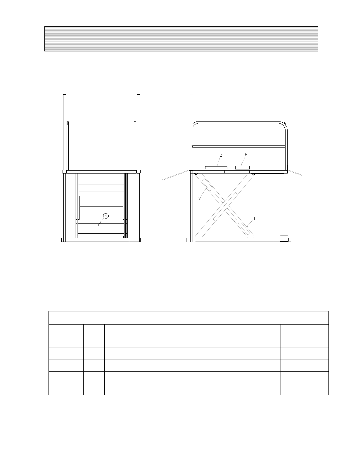
LABEL IDENTIFICATION
Figure 1 Label Placement
PLD Scissors Lift
Item No. Qty Description Part No.
1 2 Caution: Familiarize Yourself With Operators Manual 36401487
2 2 Danger – Do Not Put Hands Or Feet . . . 36430050M
31Autoquip Serial Number Nameplate 36401511
4 2 Capacity 36401586
5 1 Fill with Recommended Oils Only 36400661
8
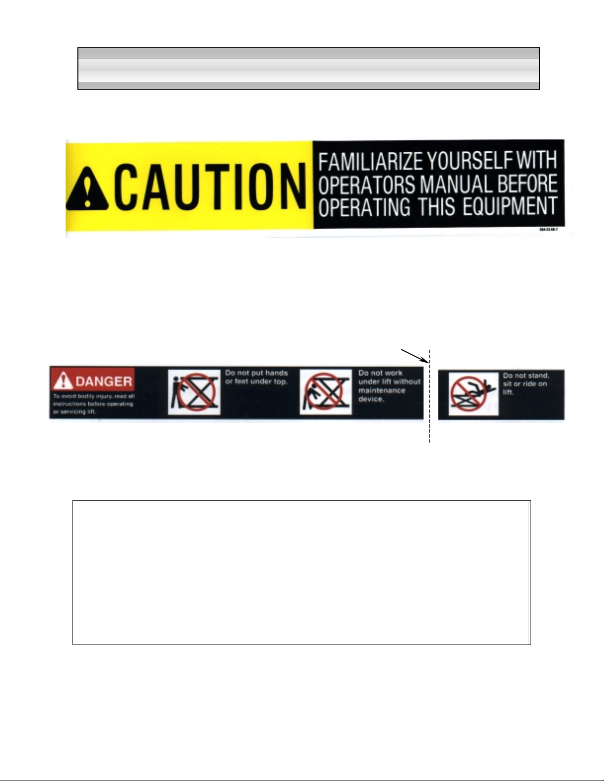
LABEL IDENTIFICATION
Note: Labels shown here are not actual size.
Figure 2 Label 36401487
CUT LINE
Figure 3 Label 36430050M
Figure 4 Label 36401511
9
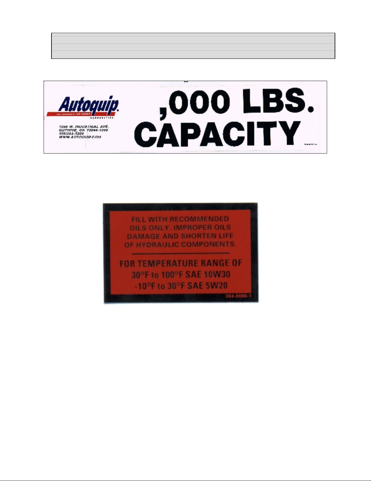
LABEL IDENTIFICATION
Figure 5 Label 36401594
Figure 6 Label 36400661
10

SPECIFICATIONS
Model Lifting
Cap.
(lbs)
PLD-20 2,000 _ 1,500 62 6 1/2 6 60 x 84 48 x 78 1,200
PLD-30 3,000 _ 1,500 62 6 1/2 6 60 x 84 48 x 78 1,350
PLD-50 5,000 5 3,000 61 1/2 6 12 72 x 96 70 x 93 1/2 3,000
Std.
Motor
HP
Axle Load
Capacity
Over
Bridge End
(lbs)
Max
Raised
Height
(Inches)
Min.
Lowered
Height
(Inches)
Travel
Speed
Platform
Size
(Inches)
Base Frame
Size
(Inches)
Ship
Wt
(lbs)
NOTE: All models have 2 rams, an approach ramp size of 24” x 48”, and have a
maximum travel of 55 _”.
LOAD CAPACITY
The load capacity rating is stamped on a metal plate attached to one side of the lift.
This figure is a net capacity rating for a lift furnished with the standard platform. The
relief valve of the pumping unit has been set to raise the weight, plus a small amount for
overload. Where gravity roll-sections, special tops, etc, are installed on the lift after
leaving the plant, deduct the weight of these from the load rating to obtain the net
capacity. Lifts should not be overloaded beyond the established capacity as
damage and/or personal injury may result.
UNBALANCED LOADING
The stabilization provided is basically for balanced loads. If special attachments extend
beyond the length and/or width dimensions of the platform, the end and/or side load
capacity must be reduced (contact an Autoquip Sales representative).
PUMP PRESSURE
This lift incorporates a positive displacement pump machined to a high degree of
accuracy and specially adapted to requirements of higher-pressure ranges over that of
a standard pump. Therefore, standard factory models of the same manufacture cannot
replace it.
The pump can operate efficiently at intermittent pressures up to 3200 PSI and
continuous duty to 2500 PSI. The safety relief valve in the pump assembly is factoryset to stay within the parameters of the pump and lift requirements.
11

LIFT BLOCKING INSTRUCTIONS
1. Remove all load from the platform. Never block the lift when loaded.
2. Raise the platform sufficiently for the base rollers to rollback past the flip-over
maintenance locks, located on the base frame of the lift.
3. Engage both maintenance locks by flipping them into the base frame (see Figure 7).
4. Lower the platform until the base rollers come into contact with and rest against the
maintenance locks. Always hold the “DOWN” switch a few seconds more until all
pressure is gone and the platform is supported entirely and safely by the
maintenance locks.
5. Always shut off the main electrical switch, when blocked, to prevent someone from
turning it on.
DANGER!
To avoid personal injury, NEVER go under the platform until the load is
removed and the lift is securely blocked in the open position.
6. To remove the maintenance locks, raise the platform by activating the “UP” switch to
provide sufficient clearance for the removal of the maintenance locks.
DANGER!
Maintenance locks that are bent, damaged, or non-functional must be
replaced immediately to avoid personal injury. Contact the Autoquip
Service Department for replacement parts and installation instructions.
12
 Loading...