

Autoquip GATES SWING User Manual
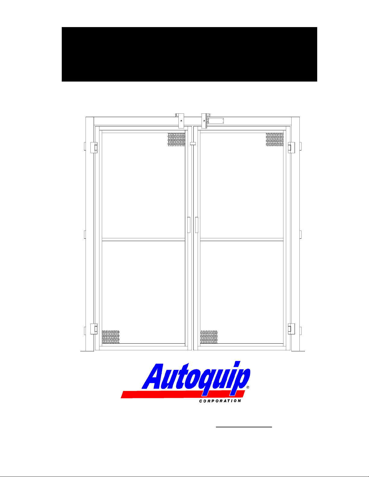
GATE & ENCLOSURE
INSTALLATION MANUAL
SWING GATES
P.O. Box 1058 • 1058 West Industrial Avenue • Guthrie, OK 73044-1058 • 888-811-9876 •
405-
282-5200 • FAX: 405-282-3302 • www.autoquip.com
Item # 830SG Version 2.0
01/2008

TABLE OF CONTENTS
Introduction 3
Inspection and Identification 4
Pre-Installation Site Visit 5
Responsibility of Owners/Users 6
Safety Signal Words 7
Safety Practices 8
Label Placement 10
Gate Installation Instructions 13
Enclosure Installation Instructions 33
Routine Maintenance 36
Replacement Parts List 37
Warranty 38
IMPORTANT
Please read and understand this manual prior to operation. If any questions should
arise, call a local representative or Autoquip Corporation at 1-888-811-9876 or 405-282-
5200.
PLANNED MAINTENANCE PROGRAM
A local Autoquip representative provides a Planned Maintenance Program (PMP) for
this equipment using factory-trained personnel. Call a local representative or Autoquip
Corporation at 1-888-811-9876 or 405-282-5200 for more information.
2

Autoquip Corporation has designed and manufactured these gates and enclosures to
conform to ANSI Standard B20.1b in order to provide personnel protection from moving
loads on the lift and to ensure safe access to the lift at every operating level. They have
been built to provide many years of dependable service and proper installation of this
equipment is vital to personnel safety. It is vital for the installers to read and
understand this manual! These instructions have been prepared and organized to
assist the installers and it is important for these individuals to carefully follow the steps
in the order they are presented!
Situations may arise which are not covered in these installation instructions. If you have
questions, please call Autoquip Customer Service at (405) 282-5200 or 1-888-811-
9876.
NOTE: Unless otherwise stated, mechanical installation does not include
unloading, permits, seismic calculations, or extensive acceptance testing. The
requirements of each contract should be carefully reviewed for possible conflicts
of interpretation.
INTRODUCTION
3

INSPECTION & IDENTIFICATION
The following items are typically shipped loose within each manually operated Vertical
Gate order:
A. Gate with posts, header, and expanded metal panel(s)
B. Interlock Kits
C. Misc. Gate Mounting Hardware, Manual, and Signs/Labels
D. Varies – Expanded Metal Enclosure Panels per General Arrangement Drawing
E. Varies – Enclosure Panel Mounting Tek-Screws, Top Caps, Corner Angles
NOTE: The “Bill of Lading” will state the number of pieces shipped. TWO ITEMS
MAY BE BANDED TOGETHER AND COUNT AS ONE PIECE.
Upon receipt of the shipment, check for exposed damage or shortages and make note
of it on the trucking company Bill of Lading or the Shipping Papers. Reports of
concealed damage to items contained in crates must be reported within 48 hours. DO
NOT destroy the crating while opening it to inspect the contents. If damage is
suspected or found, report it directly to the carrier. DO NOT contact Autoquip
Corporation!! All shipments are FOB from the Autoquip plant. Any claims for damage
must be filed with the carrier. Any parts shipped from Autoquip that are intended
to replace damaged or lost items will be invoiced to the ordering party.
Assuming no damage has occurred to the crate, check the components against the
packing list. This will provide assurance that every item shipped has been received.
Everything needed for the installation should be available. If not, report any shortages to
Autoquip Corporation within 10 days. (Autoquip is not responsible for parts lost, stolen
or damaged during transportation, storage, installation, or during any other
circumstances or conditions that may be beyond corporate control.)
Before beginning the installation process, look at the skid that the gates and enclosures
arrived on. Check for any damage and compare the packing list to the gates and
enclosures to ensure that everything is on hand. If there are any missing pieces,
contact Autoquip Product Support Team at (405) 282-5200.
4

PRE-INSTALLATION SITE VISIT
SITE CONDITIONS
Whenever possible, make a pre-installation visit or call someone at the site. Installers
must be familiar with everything relative to proper installation of this equipment. Some
concerns are listed below, though listing every affecting contingency is impossible. It is
the installer’s responsibility to check the site for problems and work out solutions with
the appropriate people. Some of the areas of concern are:
1. Is the site accessible?
2. Can the equipment get through the existing doorways, halls, and shaft openings?
3. How will the unit be raised, set into position, and accessed?
4. Can a chain fall be hooked to an available overhead support?
5. Is there a forklift available?
6. Is bracing required?
7. Look for problem areas such as bracing and overhead interference from ducts,
joists, and pipes.
It is always best to be prepared, so do as much pre-planning as possible before the
installation procedure actually begins. Learn about the site, the equipment, and the
installation process.
5

RESPONSIBILTY OF OWNERS/USERS
CODE COMPLIANCE
Ultimate responsibility for gaining state and local code approval is the responsibility of
the buyer of the VRC. Please acquaint yourself with the permitting and/or licensing
expenses and requirements of the local regulatory agencies in the installation area.
.
INSPECTION & MAINTENANCE
The gates & enclosures shall be inspected & maintained in proper working order in
accordance with Autoquip’s operating/maintenance (O&M) manual and with other
applicable safe operating practices.
REMOVAL FROM SERVICE
Any gate not in safe operating condition such as, but not limited to, missing parts or
fasteners, any bent or cracked structural members, cut or frayed electric lines, damaged
or malfunctioning controls or safety devices, etc. shall be removed from service until it is
repaired to the original manufacturer’s standards.
REPAIRS
All repairs shall be made by qualified personnel in conformance with Autoquip’s
instructions.
OPERATORS
Only trained and authorized personnel shall be permitted to operate the lift and gate.
BEFORE OPERATION
Before using the lift and gate, the operator shall have:
• Read and/or had explained, and understood, the manufacturer’s operating
instructions and safety rules.
• Inspected the lift for proper operation and condition. Any suspect item shall be
carefully examined and a determination made by a qualified person as to
whether it constitutes a hazard. All items not in conformance with Autoquip’s
specification shall be corrected before further use of the lift.
DURING OPERATION
The lift and gate shall only be used in accordance with Autoquip’s O&M manual.
• Do not overload the lift.
• Ensure that all safety devices are operational and in place.
MODIFICATIONS OR ALTERATIONS
Modifications or alterations to this equipment shall be made only with written permission
of Autoquip. Autoquip does not foresee and does not anticipate unauthorized
modifications, and these changes or alterations are grounds for voiding all warranties.
6
SAFETY SIGNAL WORDS
SAFETY ALERTS (Required Reading!)
The following SAFETY ALERTS are intended to create awareness of owners, operators,
and maintenance personnel of the potential safety hazards and the steps that must be
taken to avoid accidents. These same alerts are inserted throughout this manual to
identify specific hazards that may endanger uninformed personnel. Identification of
every conceivable hazardous situation is impossible. Therefore, all personnel have the
responsibility to diligently exercise safe practices whenever exposed to this equipment.
____________________________________________________________
DANGER!
Identifies a hazardous situation which, if not avoided, will result in death or
severe personal injury.
_____________________________________________________________
WARNING!
Identifies a hazardous situation which, if not avoided, could result in death
or serious personal injury.
CAUTION!
Identifies a hazardous situation which, if not avoided, may result in minor or
moderate personal injury.
_____________________________________________________________
CAUTION!
Caution used without the safety alert symbol indicates a potentially
hazardous situation which, if not avoided, may result in property or equipment
damage.
7
SAFETY PRACTICES
DANGER!
High voltage! May cause personal injury or death. Repairs should only
be performed by a qualified service/control technician!!
DANGER!
Qualified personnel only!! Only qualified service
personnel should perform procedures labeled as “da
ngerous”!
DANGER!
Be sure of equipment stability! To avoid personal injury or
death, check for stability. If the supports seem unstable, do not operate!
Contact Autoquip immediately!
DANGER!
Turn off power! To avoid personal injury or death, be sure
the power is off and is locked out per OSHA Lock-Out, Tag-Out
procedures!
DANGER!
Practice field safety procedures! To avoid personal injury or death,
utilize all applicable precautions for steel erection and equipment assembly
in addition to OSHA regulations for lock-out, tag-out, etc.!
8
SAFETY PRACTICES
WARNING!
Support all posts and components! Illustrations in this manual may show
them unsupported. This is done in order to make the equipment and its
installation clearly understood. Be sure to properly secure all gate posts
and panels to ensure a safe and stable installation.
WARNING!
Never run the unit with the gates or doors open! The gates must not
open when the lift is in operation or when the platform is not present.
Should this condition exist, the interlock is not functioning properly due to
incorrect installation or damage. This condition must be corrected
immediately. Failure to correct this condition may result in serious injury or
death.
WARNING!
Never operate unit when parts are defective! Do not operate this
equipment when substandard or defective parts are in use! Contact an
Autoquip Service Representative to rectify all such situations.
9
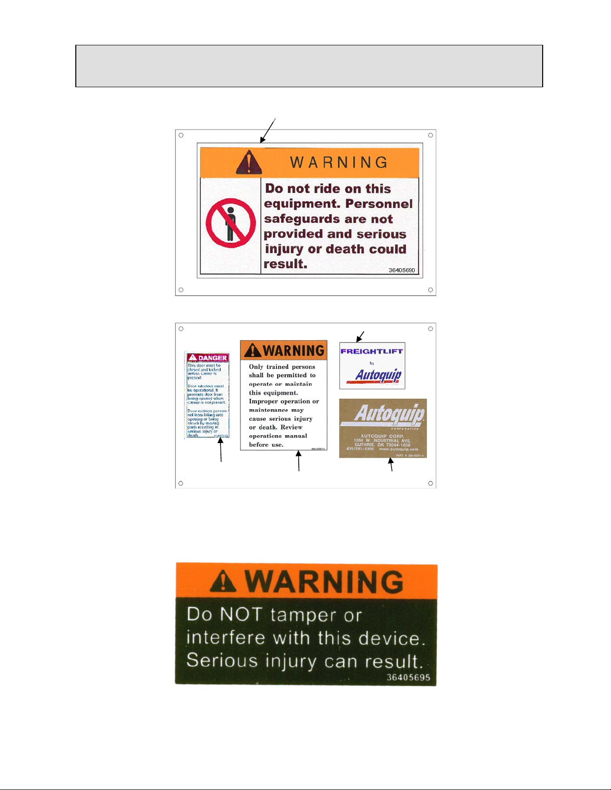
LABEL PLACEMENT
36405690
36402680
36405680
Figure 1 - Label Placement
36405670 36403210
Figure 2 – 36405695
10
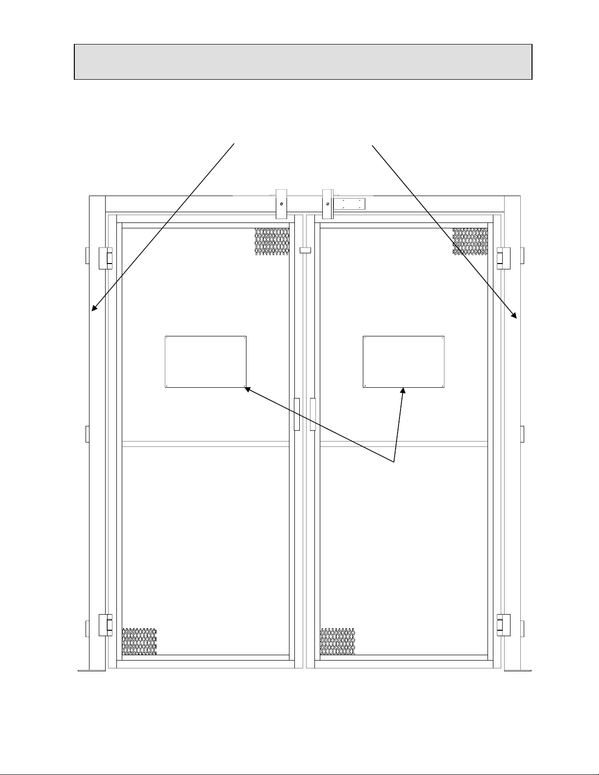
LABEL PLACEMENT
Additional 36405680
Decal installed on the
Gate Post, Same side
as the Push-Button
Station
Decal Plates shown in
Figure 1 should be
attached to gate in
this area with
hardware provided
Figure 3a – Bi-Part Gate Label Placement
11
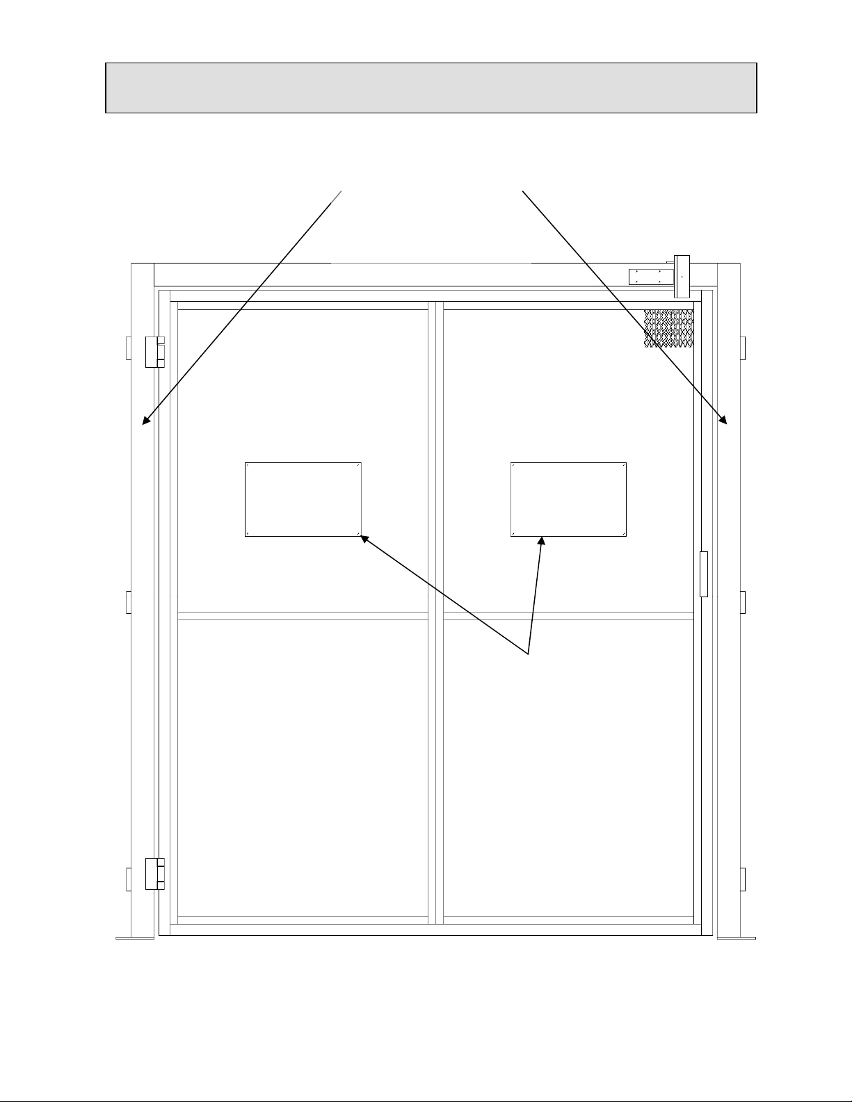
LABEL PLACEMENT
Additional 36405680
Decal installed on the
Gate Post, Same side
as the Push-Button
Station
Decal Plates shown in
Figure 1 should be
attached to gate in
this area with
hardware provided
Figure 3b – Single Swing Gate Label Placement
12
 Loading...