

INSTALLATION, OPERATION,
AND SERVICE MANUAL
TROJAN COIL CAR
P.O. Box 1058 • 1058 West Industrial Avenue • Guthrie, OK 73044-1058 • 405-282-5200 •
FAX: 405-282-8105 • www.autoquip.com
Item # 830CC Version 1.0
09/2001

TABLE OF CONTENTS
Identification and Inspection 3
Dangers, Warnings, and Cautions 4
Label Identification 8
Specifications 11
Lift Blocking Instructions 12
Installation Instructions 14
Operating Instructions 17
Routine Maintenance 19
General Maintenance 22
Replacement Parts List 31
Troubleshooting Analysis 32
IMPORTANT
Please read and understand this manual prior to installation or operation of this unit.
Failure to do so could lead to property damage and/or serious personal injury. If any
questions arise, call a local representative or Autoquip Corporation at 1-888-811-9876
or 405-282-5200.
PLANNED MAINTENANCE PROGRAM
A local Autoquip representative provides a Planned Maintenance Program (PMP) for
this equipment using factory-trained personnel. Call a local representative or Autoquip
Corporation at 1-888-811-9876 or 405-282-5200 for more information.
2

IDENTIFICATION & INSPECTION
IDENTIFICATION
When ordering parts or requesting information or service on this unit, PLEASE REFER
TO THE MODEL AND SERIAL NUMBER. This information is on a nameplate attached
to the leg assembly. Replacement parts are available from a local Autoquip distributor.
INSPECTION
Immediately upon receipt of the unit, a visual inspection should be made to determine
that it has not been damaged in transit. Any damage found must be noted on the
delivery receipt. In addition to this preliminary inspection, the unit should be carefully
inspected for concealed damage. Any concealed damage found that was not noted on
the delivery receipt should be reported in writing to the delivering carrier within 48 hours.
The following is a checklist that will aid in the inspection of the lift.
1. Examine the entire unit for any signs of mishandling. Pay special attention to the
power unit and pushbuttons.
2. Thoroughly examine all connections, making sure they have not vibrated loose
during transit.
3. After installation, raise the lift and inspect the base frame, platform, scissors
assembly, and cylinder plumbing connections.
3
DANGERS, WARNINGS & CAUTIONS
SAFETY ALERTS (Required Reading!)
The following SAFETY ALERTS are intended to create awareness of owners,
operators, and maintenance personnel of the potential safety hazards and the steps that
must be taken to avoid accidents. These same alerts are inserted throughout this
manual to identify specific hazards that may endanger uninformed personnel.
Identification of every conceivable hazardous situation is impossible. Therefore, all
personnel have the responsibility to diligently exercise safe practices whenever exposed
to this equipment.
____________________________________________________________
DANGER!
Identifies a hazardous situation that presents the imminent probability of
death or of severe personal injury!!
_____________________________________________________________
WARNING!
Identifies a hazardous situation that has the potential of causing death or
serious personal injury.
CAUTION!
Identifies a hazardous situation that could lead to the possibility of personal
injury of death, and/or may result in equipment damage.
_____________________________________________________________
4
DANGERS, WARNINGS & CAUTIONS
Read and understand this manual and all labels prior to operating or
servicing the scissors lift. All labels are provided in accordance with
ANSI Z535.4.
DANGER!
Do not work under lift without maintenance device! To avoid personal
injury, NEVER go under the lift platform until the load is removed and the
scissors mechanism is securely blocked in the open position. See the "Lift
Blocking Instructions" section.
DANGER!
To avoid personal injury, stand clear of scissors leg mechanism while lift is
in motion.
DANGER!
Do not install the lift in a pit unless it has a bevel toe guard or other
approved toe protection. A shear point can exist which can cause severe
injury to the foot.
DANGER!
HIGH VOLTAGE!! Disconnect and/or lock out the electrical supply to the
power unit prior to any maintenance being performed.
5
DANGERS, WARNINGS & CAUTIONS
DANGER!
Scissors lifts are designed individually for a specific load and application.
To avoid personal injury, do not change the load or application from the
original design.
WARNING!
NEVER stand, sit or ride on the lift!
WARNING!
All warning and information decals should be in place as outlined in the
“Label Identification” section. If decals are missing or damaged, they
should be replaced with new ones. Contact Autoquip for replacements.
WARNING!
Do not attempt to remove the velocity fuse until the maintenance block
securely supports the lift and all hydraulic pressure has been removed from
the lifting cylinders and hydraulic hoses. Failure to do so could results in
personal injury or death!
CAUTION!
Do not continue to depress the “UP” button on the controller if the lift is not
raising or if the lift has reached the fully raised position. To do so may
result in permanent damage to the motor or pump.
6

DANGERS, WARNINGS & CAUTIONS
CAUTION!
Never run the pump for more than a couple of seconds without pumping oil.
This applies to low oil conditions, improper motor rotation, running the
pump against the relief pressure after the lift is fully raised against the
physical stops, running overloaded beyond capacity, or running at reduced
speed because of pinched or obstructed hydraulic lines.
CAUTION!
Do not operate the power unit on relief for more than a few seconds. When
on relief, the valve will make a squealing sound.
CAUTION!
Precautions should be taken to prevent the introduction of contaminates
such as dirt or other foreign material into the system through open fittings,
pipes or disassembled components. Contamination will ruin the hydraulic
system.
CAUTION!
Use only approved oils in the lift. See “Specifications” section.
7
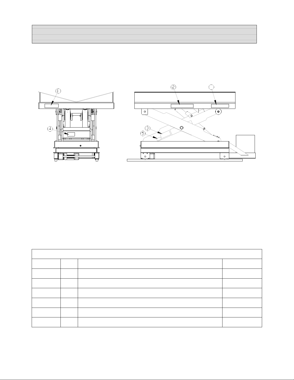
LABEL IDENTIFICATION
6
Figure 1 Label Placement
Coil Car
Item No. Qty Description Part No.
1 2 Caution! Familiarize Yourself With Operators Manual 36401487
2 4 Danger – Do Not Put Hands or Feet . . . 36430050
31Autoquip Serial Number Nameplate 36401511
4 1 Fill with Recommended Oils Only 36400661
5 2 UP – STOP Valve (when applicable) 36401610
6 2 Capacity 36401586
8
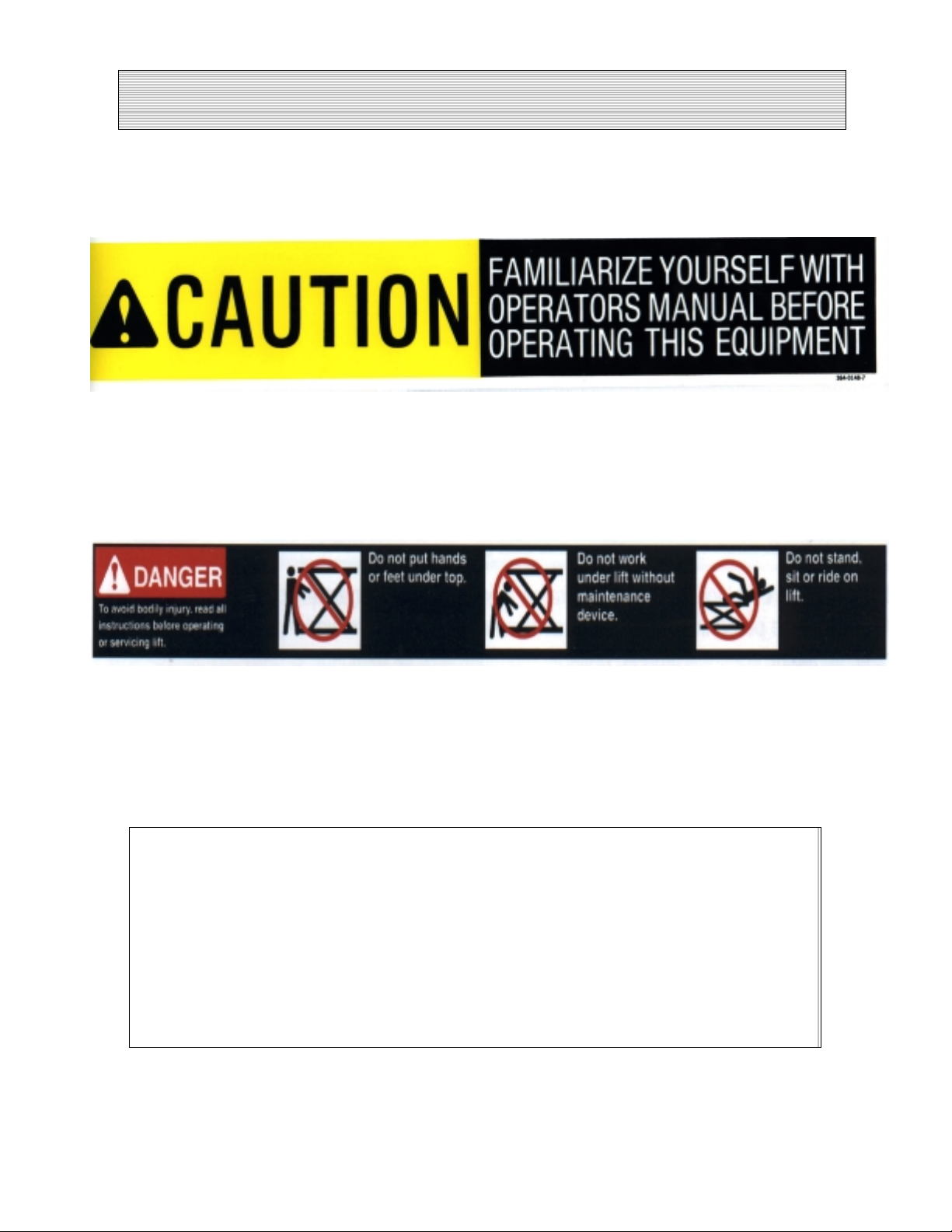
LABEL IDENTIFICATION
Note: Labels shown here are not actual size.
Figure 2 Label 36401487
Figure 3 Label 36430050
Figure 4 Label 36401511
9
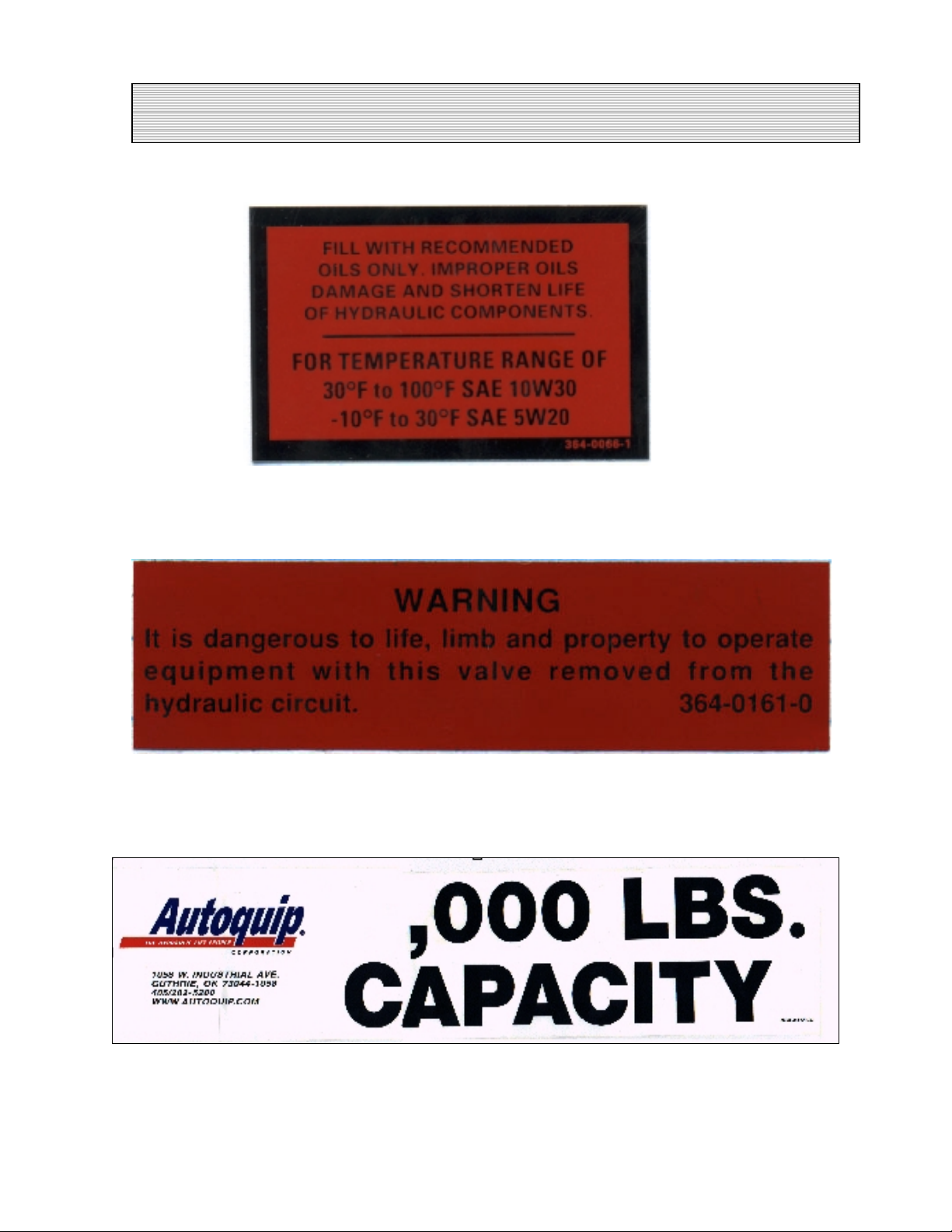
LABEL IDENTIFICATION
Figure 5 Label 36400661
Figure 6 Label 36401610
Figure 7 Label 36401586
10

SPECIFICATIONS
LOAD CAPACITY
The load capacity rating is stamped on a metal plate attached to one side of the lift.
This figure is a net capacity rating for a lift furnished with the standard platform. The
relief valve of the pumping unit has been set to raise the weight, plus a small amount for
overload. Where gravity roll-sections, special tops, etc, are installed on the lift after
leaving the plant, deduct the weight of these from the load rating to obtain the net
capacity. Lifts should not be overloaded beyond the established capacity as
damage and/or personal injury may result.
UNBALANCED LOADING
The stabilization provided is basically for balanced loads. If special attachments extend
beyond the length and/or width dimensions of the platform, the end and/or side load
capacity is reduced 2% for each one-inch extension from the center.
PUMP PRESSURE
This lift incorporates a positive displacement pump machined to a high degree of
accuracy and specially adapted to requirements of higher-pressure ranges over that of
a standard pump. Therefore, standard factory models of the same manufacture cannot
replace it.
The pump can operate efficiently at intermittent pressures up to 3200 PSI and
continuous duty to 2500 PSI. The safety relief valve in the pump assembly is factoryset to stay within the parameters of the pump and lift requirements.
DEMAG DRIVE SYSTEM
The Coil Car incorporates an electric traverse drive system with a motor and gearbox
speed reducer directly driving a splined shaft and two drive wheels in high capacity
wheel “pockets” attached to each side of the lift. Most components in this Demag drive
system are specially machined, high precision, and metric; they should not be replaced
with non-Demag components.
11

LIFT BLOCKING INSTRUCTIONS
1. Remove all load from the platform. Never block the lift when loaded.
2. Raise the platform sufficiently for the base rollers to rollback past the flip-over
maintenance locks, located on the base frame of the lift.
3. Engage both maintenance locks by flipping them into the base frame (see Figure 8).
4. Lower the platform until the base rollers come into contact with and rest against the
maintenance locks. Always hold the “DOWN” switch a few seconds more until all
pressure is gone and the platform is supported entirely and safely by the
maintenance locks.
5. Always shut off the main electrical switch, when blocked, to prevent someone from
turning it on.
DANGER!
To avoid personal injury, NEVER go under the platform until the load is
removed and the lift is securely blocked in the open position.
6. To remove the maintenance locks, raise the platform by activating the “UP” valve to
provide sufficient clearance for the removal of the maintenance locks.
DANGER!
Maintenance locks that are bent, damaged, or non-functional must be
replaced immediately to avoid personal injury. Contact the Autoquip
Service Department for replacement parts and installation instructions.
12

LIFT BLOCKING INSTRUCTIONS
FLIP-OVER MAINTENANCE
LOCKS, ON BOTH SIDES OF
THE BASE FRAME.
Figure 8 Maintenance Locks
13

INSTALLATION INSTRUCTIONS
INSTALLATION
1. Make sure installation area is clean before starting.
2. If the permanent electrical work is not complete, some means of temporary lines with
an on-off device for the motor should be set up for testing purposes.
3. Place the lift in the installation area, typically on tracks or rails which are supplied
and installed by the customer or installer.
CAUTION!
When moving the lift, do not attempt to pick it up by the platform; it is
hinged and could be damaged. Pick up the lift from under the base frame
ONLY using a strap sling.
4. Make temporary electrical connections. Raise the lift to the top of its travel and
check for the proper height.
DANGER!
Do not work under lift without Maintenance Device! To avoid personal
injury, NEVER go under the lift platform until the load is removed and the
scissors mechanism is securely blocked in the open position. See "Lift
Blocking Instructions" section.
5. Run the lift in forward and reverse and check for proper motor rotation and speed.
6. Make permanent electrical connections and operate the lift through a few cycles.
7. Check the oil in the reservoir and add oil, if necessary. See “Routine Maintenance”
section.
8. Clean up any debris from the area. A clean installation makes a good impression
and creates a much safer environment!
14

INSTALLATION INSTRUCTIONS
PROCEDURE FOR A LIFT ORDERED WITH AN ACCORDION SKIRT
1. Position the platform in the raised position. Install the maintenance locks (see “Lift
Blocking Instructions” section). Position the accordion with the weight rod pocket at
the bottom and the mounting collar at the top. The breathable material when
provided must be positioned at the top of the skirt with the mounting collar.
2. Slip the skirt over the end of the platform. Turn the skirt as required to slide over the
other end of the platform and leg assembly. The skirt should be in position under
the platform while enveloping the base assembly.
3. See Figure 10 and select the correct mounting configuration (Figure 1, 2, or 3).
Figure #1: Mounting an Accordion Skirt Onto the Platform Side
Raise one side of the skirt along with a skirt -mounting bar (1/8” x 1”) to (1) side of
the platform. When possible, center the skirt-mounting collar and skirt-mounting bar
(1/8” x 1”) on the platform side. Align the pre-drilled holes in the side of the platform
with the skirt-mounting bar holes and punch holes in the skirt-mounting collar. Push
a nylon drive rivet through each hole in the skirt-mounting bar. Hammer the
aluminum pin into the rivet until flush with the rivet head. Repeat mounting process
for the remaining sides of the accordion skirt.
Figure #2: Mounting an Accordion Skirt Underneath the Platform
Raise one side of the skirt along with a skirt-mounting bar (1/8" x 1") to the
underside of the platform skirt support bar. When possible, center the skirt mounting
collar and the skirt-mounting bar (1/8” x 1”) on the platform support bar. Align the
pre-drilled holes in the skirt support bar (picture frame) with the skirt -mounting bar
holes and punch holes in the skirt-mounting collar. Push a nylon drive rivet through
each hole in the skirt-mounting bar. Hammer the aluminum pin into the rivet until
flush with the rivet head. Repeat mounting process for the remaining sides of the
accordion skirt.
Figure #3: Mounting an Accordion Skirt Onto the Bevel Toe Guard
Raise one side of the skirt along with a skirt-mounting bar (1/8” x 1”) to the side of
the bevel toe guard. When possible, center the skirt mounting collar and the skirtmounting bar (1/8” x1”) on the platform bevel toe guard. Align the pre-drilled holes in
the bevel toe guard with the skirt-mounting bar holes and punch holes in the skirtmounting collar. Push a nylon drive rivet through each hole in the skirt-mounting
bar. Hammer the aluminum pin into the rivet until flush with the rivet head. Repeat
mounting process for the remaining sides of the accordion skirt.
4. Install weight rods into the weight rod pockets at the bottom of the accordion skirt.
Install the spring tempered wire rods into the pocket of black convolutions.
15

INSTALLATION INSTRUCTIONS
Figure 9 Skirt Installation
16

OPERATING INSTRUCTIONS
Familiarize yourself with this operator’s manual before operating this equipment.
CAUTION!
Do not continue to depress the “UP” button on the controller if the lift is
not raising or if the lift has reached the fully raised position. To do so may
result in permanent damage to the motor or pump.
Scissors lifts are designed primarily for in-plant applications and are furnished with
constant pressure pushbutton and footswitch controls. Actuating the "UP" button
causes the coil on the contactor to energize, closing the line contacts and allowing the
line voltage to be applied to the motor. The motor will drive a gear pump, which in turn
draws oil from the reservoir through the pump and forces it at a constant volume under
pressure required by the load. The oil flows through the valves and piping into the
hydraulic cylinder. The hydraulic cylinder is attached to structural members of the lift
causing the scissor mechanism of the legs to open as the cylinder rod extends.
When the desired height or upward travel of the platform is attained, the "UP" button is
deactivated by releasing pressure from the pushbutton or footswitch. The power unit
will stop pumping oil, and the check valve will close preventing reverse flow of the oil.
This maintains the desired raised position
To lower the lift, the operator simply depresses the "DOWN" button on the pushbutton
control energizing the down valve solenoid. The solenoid activates the valve to open.
Once opened, the down valve allows oil in the hydraulic cylinder to flow through the
velocity fuse, the flow control, and the down valve at a controlled rate and return to the
reservoir. The downward travel of the lift platform may be stopped at a desired
elevation by releasing pressure from the "DOWN” button.
NOTE: The motor does not operate during downward travel.
CAUTION!
Do not operate the power unit on relief for more than a few seconds. When
on relief, the valve will make an audible squealing sound.
17

OPERATING INSTRUCTIONS
To traverse the lift the operator simply depresses either the “FORWARD” or
“REVERSE” button on the pushbutton control energizing the reversing motor starter in
the control panel. The motor starter activates the motor in either direction, which then
turns the gearbox reducer. The splined output shaft runs through the gearbox and
drives the drive wheels mounted on each side of the lift. When the desired travel is
achieved, release the pressure from either the “FORWARD” or “REVERSE” button.
Note: Even though the motor has a brake, there will be slight forward motion
after the button is released while the lift “coasts” to a complete stop.
18

ROUTINE MAINTENANCE
Normally coil cars will require very little maintenance. However, a routine maintenance
program could prevent costly replacement of parts and/or downtime.
WARNING!
To avoid personal injury, NEVER go under the lift platform or perform any
maintenance on the lift until the load is removed and the scissors
mechanism is securely blocked in the open position. See "Lift Blocking
Instructions" section.
MONTHLY INSPECTION
1. Check the hydraulic oil level (see oil recommendations in this section) and add
appropriate oil when necessary.
2. Check for any visible leaks. Correct as necessary.
3. Check any unusual noise when it occurs. Determine the source and correct as
necessary.
4. Check the snap rings at all rollers, if not in place, and/or secure, replace or repair
immediately.
5. Check all rollers for signs of wear. Replace as necessary.
6. Do not grease roller or axles; they have lifetime-lubricated bearings.
7. Check all wiring for looseness or wear. Repair at once.
8. Check gearbox “non-rotator” bracket and its connection to the structure of the base
frame to ensure it has not vibrated loose or shows signs of excessive wear.
HYDRAULIC OIL REQUIREMENTS
Change oil yearly, or more frequently if it darkens materially or feels gummy or gritty.
Do not use hydraulic-jack oil, hydraulic fluids, brake fluids, or automatic
transmission fluid.
19

ROUTINE MAINTENANCE
Oil Viscosity Recommendations
Environment
(Ambient Temperatures)
Indoor location, variable
temperatures (30 - 100° F)
Indoor location, consistent
Temperatures (70° F)
Outdoor location, (-10 - 100° F) SAE 5W30
Cold-storage warehouse
(10 - 40° F)
Freezer (-40° F to 0° F) Consult Factory
Recommended Oil
10W30 or 10W40
Multiviscosity motor oil
SAE-20W motor oil
Multiviscosity motor oil
5W30 Multiviscosity motor oil
GEARBOX LUBRICATION REQUIREMENTS
Under normal operating conditions the oil should be changed after 10,000 hours of
service. The oil should, however, be changed at least every four years.
Oil Change
1. Drain the old oil at operating temperature.
2. Remove the vent plug located at the top of the gearbox.
3. Remove the plug at the bottom, which will allow the oil to run out.
4. The oil used to flush the gearbox should have a viscosity of ISO 46 – 68 at 40ºC. To
flush the gearbox, use twice the amount of oil specified for lubrication. After a few
minutes of idle running, the oil may be drained.
5. Repeat the flushing operation several times, preferably in both directions of rotation,
and again without a load, to ensure that all remains of the old lubricant are drained
with the flushing oil.
6. Fill the gearbox with the quantity of new oil specified on the gearbox data plate.
20

ROUTINE MAINTENANCE
Oil Grades
For ambient temperatures of approximately -10ºC to +50ºC (14º to 122ºF) a gear oil
of ISO 220 at 40ºC with mild high-pressure additives should be used, DIN 51502
CLP 220, e.g. BP ENERGOL GR-XP 220, Esso Spartan EP 220, SHELL Omala Oel
220, Mobilgear 630, or Aral Degol BG 220.
At high or lower ambient temperatures, the type of oil used should be adapted to the
specific conditions. Contact the Autoquip Customer Assurance department.
Grease Lubrication
If the gearbox casing is filled with low-viscosity grease, it is recommended that this
be changed after every 10,000 hours of service.
1. Open the gearbox casing and flush it thoroughly with a commercial cleaning agent.
2. Fill the casing with new grease. The required quantity of grease is indicated on the
gearbox data plate.
Grease Quality
For ambient temperatures ranging from approximately –10ºC to +50ºC (14º to 122ºF) a
low-viscosity gear grease with a dripping point of approximately 150ºC (300ºF) and a
worked penetration of 380 to 430 1/10 mm should be used, e.g., DIN 51502 GP 00F,
z.B. BP Energrease HT EP00, SHELL Special low-viscosity gear grease H, Esso Fibrax
EP 370, or Aralub FD 00.
21

GENERAL MAINTENANCE
HYDRAULIC CYLINDER REPACKING
1. Raise the lift to its full height and block securely. See “Lift Blocking Instructions”.
2. Hold the “DOWN” control for several seconds to make sure pressure in the lines is
bled down.
3. Disconnect the cylinder hose at the power unit end and insert into the oil-fill hole of
the reservoir.
4. Remove the thrust angle clip from the ram (plunger) end of the cylinder and force
the ram slowly back to its fully closed position to push oil back into the reservoir.
5. Pull the ram all of the way out of the cylinder. Support it carefully so that it does
not drop when it clears the cylinder end. Lay it down in a safe, clean place. Some
oil may drip from the end of the cylinder so have waste cloth or paper beneath the
lift to protect the floor.
6. Remove the seal ring and backup ring.
7. After all of the internal components are removed, use a bright light to inspect the
inner walls of the barrel. Use a cylinder hone to remove any apparent nicks or
scratches. Clean and flush the barrel after honing.
8. Inspect the ram and seal groove for nicks or scratches that could affect the seal or
barrel walls; remove as necessary.
9. Clean the groove thoroughly and install the new seal and backup. Make sure the
backup ring is toward the open end of the cylinder.
10. Clean the ram of all foreign materials.
11. Liberally lubricate the ram and seal with CLEAN grease or oil.
12. Insert the ram carefully back into the cylinder taking precaution against pinching or
tearing the seal ring.
13. Reinstall the clip over the thrust angle.
14. Reconnect the cylinder hose.
22

GENERAL MAINTENANCE
15. Restore the oil level.
16. Loosen the bleeder plug at the top end of the ram casing and operate the pump to
remove trapped air from the ram. When clear oil appears, tighten the plug and
raise the lift slightly to remove the maintenance locks.
17. Lower the lift completely and hold the “DOWN” button for 30-40 seconds to allow
air in the lines to bleed back into the tank.
18. Cycle the lift 10 – 15 times.
19. Check the oil level.
20. Clean the oil fill breather cap.
21. Clean up any debris and/or spilled oil from the area.
NOTE: Depending on experience, the job should take 1 – 2 hours.
PIPE THREAD SEALANT
Loctite PST #567 pipe thread sealant or equivalent is recommended. Do not use
Teflon tape. Tape fragments can cause malfunctioning of the hydraulic system.
23

GENERAL MAINTENANCE
CYLINDER VELOCITY FUSE REPLACEMENT
DANGER!
Do not attempt to remove the velocity fuse until the lift is securely
supported with the maintenance locking devices and all hydraulic pressure
has been removed from the lifting cylinders and hydraulic hoses. Failure
to follow these instructions could result in personal injury or death!
Never attempt to take a velocity fuse apart and repair it. These are precision devices
that are factory assembled under exacting conditions. Velocity fuses should always be
replaced.
1. The arrow on the exterior surface of the velocity fuse shows the direction of the
restriction to the oil flow. The arrow should always point away from the cylinder.
2. Do not use Teflon tape on the threaded connections of a velocity fuse. Tape
fragments can cause malfunctioning of the fuse.
3. Check all fitting connections for hydraulic leaks and tighten as necessary.
HOSE ORIENTATION
To prevent damage to the cylinder hose and possible failure of lift, it is necessary to
establish a correct hose shape and pattern of movement as follows:
1. Raise the lift to its full height and block securely. See “Lift Blocking Instructions”.
2. Install one end of the new hose to the cylinder elbow fitting for single cylinder lifts, or
to the hosing tee or cross for multiple cylinder lifts.
3. Since some hoses are fixed at both ends, it is possible to put a twist in the hose that
will allow it to describe the same pattern each time the lift is operated. This twist will
allow the hose to travel about half way between the cylinder on the right side and the
inner leg on the right side.
4. Lower the lift carefully and check to see that the hose is free and clear of the cylinder
and the inner leg assembly. If not, twist the hose in the direction necessary to clear
it of any obstruction and then lock the swivel fitting securely.
24

GENERAL MAINTENANCE
LIFTING
CYLINDERS
(1) VELOCITY FUSE PER CYLINDER.
QUANTITY OF CYLINDERS AND
VELOCITY FUSES DEPENDS ON
MODEL OF LIFT USED.
VELOCITY FUSES
PRESSURE LINE
RETURN
LINE FILTER
RELIEF
VALVE
LOWERING VALVE AND PRESSURE LINE FILTRATION.
DELTATROL VALVE PROVIDES COMPLETE,
COMPENSATED FLOW CONTROL, SOLENOID
THE FUNCTION OF CHECK, RELIEF, PRESSURE
CHECK VALVE
P.F.
RESTRICTOR
DOWN SPEED
LINE
SUCTION
FILTER
RESERVOIR
SEPERATE FILTER IS SPECIFIED.
SUCTION LINE FILTER IS INTERNAL
TO DELTATROL BLOCK UNLESS A
M
Figure 10 Hydraulic Schematic – Heavy Duty Motor
25

GENERAL MAINTENANCE
Figure 11 Hydraulic Schematic – Super Torque Motor
26

GENERAL MAINTENANCE
WIRING AUTOQUIP "SUPER TORQUE' MOTORS
Because Autoquip "Super-Torque" motors actually deliver substantially more
horsepower than their nameplate rating, they must always be wired for heavier currentdraw than standard motors of the same nameplate rating. However, because of the
starting efficiency and superior running characteristics of the "Super-Torque" motor,
circuit components do not have to be as large as for standard motors of equal delivered
horsepower.
The following chart should be referenced in connecting these motors to power sources,
remembering that, where 115-Volt operation is contemplated, the current-draw is too
heavy for plugging into ordinary lighting circuits. Heavy wire must be used all the way to
the power-source.
HP and Source Fuse
1_ HP / 208-230 V/60 CY/3 PH 15 A 10 A
1_ HP / 460 V/60 CY/ 3 PH 7.5 A 5 A
NOTE: For larger horsepower motors, consult factory.
MOTOR CONNECTION DIAGRAMS
Size
Circuit
Breaker
27

GENERAL MAINTENANCE
LIFT UP-STOP VALVE (when used)
The up-stop valve is bolted to a mounting plate that is permanently welded near the end
of the scissors leg on the clevis end of the lift. A mechanical plunger is located on the
end of the valve which, when depressed, blocks the flow of oil until physically released.
An adjustable striker bolt is mounted to a plate that is welded to the base frame, which
is also at the clevis end of the lift. As the lift travels upward, the scissors leg and upstop valve assembly swings into the adjustable striker bolt until the up-stop plunger is
depressed and thereby blocking the flow of oil to the cylinders. Once blocked, any
further oil pumped from the power unit will pass over the relief back to the tank.
CAUTION!
Do not operate the power unit on relief for more than a few seconds. When
on relief, the valve will make an audible squealing sound.
The up-stop system can be adjusted to modify vertical travel by:
1. Loosen the holding nuts on either side of the adjustable striker bolt.
2. Screw the adjustable striker bolt in (to shorten travel) or out (to raise travel).
3. Retighten the holding nuts.
CAUTION!
Setting the up-stop valve for travel beyond catalogue limits will cause the lift
to fully raise against physical stops and, if the pump is allowed to continue to
run, cause irreversible damage to the lift structure.
28

UP-STOP VALVE
MOUNTING PLATE
OUTPUT PRESSURE
HOSE (TO CYLINDERS)
GENERAL MAINTENANCE
LEG
UP-STOP VALVE
PLUNGER
HOSE (FROM POWER UNIT)
INPUT PRESSURE
UP-STOP VALVE
MOUNTING SCREW
ADJUSTABLE STRIKER
BOLT / BAR
BASE CLEVIS
BLOCK
UP-STOP VALVE
Figure 12 Up-Stop Valve System
29

GENERAL MAINTENANCE
Figure 13 Electro-Hydraulic Schematic; Lift & Traverse Combination
30

REPLACEMENT PART
S
LIST
Specific part numbers vary from job to job, depending on the model and options chosen
for the application. Call the Autoquip Service Department with the serial number of the
specific equipment to order the appropriate parts.
DRIVEN
WHEEL
DRIVEN
WHEEL
DRIVE
WHEEL
DEMAG
GEAR BOX
DEMAG
BREAK MOTOR
DEMAG
BREAK MOTOR
DRIVE
SHAFT
DEMAG
GEAR BOX
IDLE
WHEEL
IDLE
WHEEL
IDLE
WHEEL
POWER
SUPPLY
POWER
SUPPLY
IDLE
WHEEL
POWER
SUPPLY
IDLE
WHEEL
DRIVEN
WHEEL
IDLE
WHEEL
Figure 14 Typical Demag Drive Asembly
31
POWER
SUPPLY

TROUBLESHOOTING ANALYSIS
DANGER!
To avoid personal injury, NEVER go under the lift platform until the load is
removed and the scissors mechanism is securely blocked in the open position.
See "Lift Blocking Instructions" section.
PROBLEM POSSIBLE CAUSE AND SOLUTION
Lift raises, then lowers back
slowly.
• The "Down" solenoid may not be seating. Remove
the solenoid coil and check again. If the lift does
not hold with the solenoid coil removed, the down
valve cartridge should be removed and cleaned or
replaced as necessary.
• The oil line, hose, or fitting may be leaking. Check
and repair if necessary.
• The check valve may not be seating. This is
indicated by the pump shaft and motor turning
backward on their own with no power applied.
Generally, this condition can be heard. Replace
the pump assembly.
Lift lowers very slowly. • The down-solenoid is not operating properly due to
dirt or damage.
• Check for pinched tubing or hose. Where pipe is
used, check for obstruction in the line.
• The oil is extremely viscous due to low ambient
temperatures. Add or replace with lower weight oil
that stays thinner in cold conditions (5W-15, etc.)
32

TROUBLESHOOTING ANALYSIS
PROBLEM POSSIBLE CAUSE AND SOLUTION
Lift does not raise. • The motor rotation for a 3-phase motor may be
reversed. Reverse only two motor electrical leads.
• Check for a line or hose leak.
• Check for oil shortage in the reservoir. Add oil as
necessary (See Oil Requirements in the “Routine
Maintenance” section.)
• The load may exceed the rating. (See the
“Specifications” section.) Remove the excess load.
• The suction screen may be clogged, starving the
pump. Remove and clean the screen. Drain and
replace the oil.
• The suction line may be leaking air due to a loose
fitting. Tighten as needed.
• The breather holes in the reservoir fill plug may be
clogged. Remove and clean.
• The voltage at the motor terminals may be too low to
run the pump with the existing load. Check by
measuring the voltage at the motor terminals, or as
near as possible, while the pump is running under
load. Reading the source voltage or pump-idling
voltage is meaningless. Inadequate or incorrect
wiring can starve the motor when the source voltage
is ample. Correct as necessary.
• The "Down" valve may be energized by faulty wiring
or stuck open. Remove the solenoid and check.
• The motor may be single phasing. Check wiring,
fuses, etc.
• The pump may be seized if motor is humming or
blowing fuses on overload protection devices.
Remove the pump. The pump should be able to be
rotated by hand. Check for cracks in the housing.
33

TROUBLESHOOTING ANALYSIS
PROBLEM POSSIBLE CAUSE AND SOLUTION
Lift won’t lower. • The solenoid coil may be incorrectly wired,
burned out, not rated for the voltage, or the line
voltage may be excessively low. Check voltage
near the coil.
• The velocity fuse may be locked. Do not
attempt to remove the velocity fuse. The
following steps should be followed:
1. Remove the load from the lift. Inspect all
fittings, hoses, and other hydraulic components
for leads or damage.
2. If no leak or damage is noticed, attempt to
pressurize the lifting cylinder by depressing the
“UP” button on the controller for a few seconds.
Immediately up releasing the “UP” button,
depress the “DOWN” button. If the lift starts to
lower, continue pressing the “DOWN” button
until the lift is in the fully lowered position.
3. If the lift does not lower after trying Step 2,
wait approximately 10 – 15 minutes for the
pressure in the hydraulic system to equalize.
Then, depress the “DOWN” button until the lift is
in the fully lowered position.
4. Once the lift is in the fully lowered position,
bleed the air from the hydraulic system by
depressing the “DOWN” button. Hold the
“DOWN” button for approximately 60 seconds.
This step may need to be repeated several
times to fully remove the air in the system by
raising the lift to 50% of its travel and then
lowering it. For the ram-style cylinder, oil may
also bled from the bleed screw located on the
end of each cylinder casing.
• Should the above steps not correct the problem,
contact Autoquip to obtain instruction for further
action.
34

TROUBLESHOOTING ANALYSIS
PROBLEM POSSIBLE CAUSE AND SOLUTION
Lift seems bouncy during
operation.
• Lower the lift to collapsed position and continue to hold
“DOWN” button an additional 10-30 seconds to bleed
air from the bleed screws. Do not confuse spongy or
jerky operation with small surges that may occur when
operating on rough or uneven floors
WARNING!
Do not remove the bleed screw! This could cause
the lift to drop rapidly, resulting in damage to the lift
or cause personal injury. Loosen the screw
carefully to let air out of the system.
• Check for oil starvation.
Motor labors or heats
excessively.
• The voltage may be low. Check at the motor terminals
while the pump is running loaded, not at the line source
or while the pump is idling. Inadequate wiring can
starve the motor even when the source voltage is
ample.
• Most of Autoquip’s standard motors are rated for
intermittent duty (two minute run times with two minute
rests). If a single-phase motor is being run more than
15 – 20 motor starts per hour, or a 3-phase motor more
than 200 starts per hour, the problem may be motor
over-heating.
• Running against relief pressure unnecessarily due to
over loaded lift or hitting physical stops.
• Failure to observe wiring diagram on nameplate for
proper voltage connections.
• The pump may be binding from oil starvation, which
develops high internal heat. Check for low oil level or
closed breather holes in the reservoir fill plug. The
pump can be irreparably damaged by oil starvation and
may have to be replaced.
35

TROUBLESHOOTING ANALYSIS
PROBLEM POSSIBLE CAUSE AND SOLUTION
Lift won’t go forward or
reverse
• The traverse path may be blocked with debris or
other obstacle. Look under the base and
remove any obstacle that may impede travel.
• The axle may be “high centered” on some
obstacle, preventing the wheels from gaining
enough traction. Inspect under the axles and
remove any obstruction.
• The non-rotation devise may have broken or
vibrated loose. Reattach or replace bracket.
• The load may exceed the nameplate capacity
and exceed the horsepower ratings for the drive
train. Ensure the load is within the rated limits.
• There may not be enough amps available.
Check the supply amperage to ensure it
provides the minimum amperage needed per the
vendor’s specifications.
• There may be a loose electrical connection.
Make sure all electrical connections are intact
and check for shorts.
36
 Loading...