

AUTOPILOT SYSTEMS DIG-220 Service Manual

Swimming Pool and Spa Purification System
™
Pool Pilot
Digital
by AUTOPILOT SYSTEMS
INC.
Owners Manual
Pool Owner, save this manual for reference.
Installer, leave this manual with the Pool Owner.
DIG-220
Installation and Operation
(For Indoor or Outdoor Use)
IMPORTANT
Read This Manual Before Installing & Operating

Section 1a – GENERAL PRODUCT INFORMATION
™
Pool Pilot
Digital
by AUTOPILOT SYSTEMS
INC.
Record The Following Information
Installer: _________________________ Date of Installation: __________________________
Control Unit Control Unit
Model Number: DG-220 ____ Serial Number: # ____________________________
Cell Cell
Model Number: SC- ___ Serial Number: # ____________________________
Factory Direct Customer Assistance…
HOTLINE: 1.800.922.6246 or 1.954.772.2255
FAX: 1.954.772.4070
e-mail to: AutoPilotTechSupport@teamhorner.com
Visit Us On The Internet @
http://www.autopilot.com
Manufactured by
AutoPilot Systems, Inc.
5755 Powerline Road • Fort Lauderdale • Florida 33309-2074, U.S.A.
™
Pool Pilot
Digital
by AUTOPILOT SYSTEMS
INC.
1

Section 1b – GENERAL PRODUCT INFORMATION
IMPORTANT SAFETY INSTRUCTIONS
READ AND FOLLOW ALL INSTRUCTIONS
INSTALLATION AND EQUIPMENT RELATED
Installation of all Pool Pilot™ Digital models:
When installing and using your Pool Pilot™ Digital Control Box, basic safety precautions must always
be followed, including the following:
1. DANGER – Risk of electrical shock. To avoid serious injury or death,
¾ Ensure that the electrical panel or filter pump circuit is turned OFF prior to installation or servicing inside any
Autopilot unit.
¾ Mount your control box to ensure the least amount of direct exposure to rain, garden sprinkler water, direct
sunlight or any corrosive environment.
¾ Install Control Box at least 10’ (3 m) for 115VAC Units, from the inside wall of the pool or spa using non-
2. DANGER – To avoid serious injury or death, do not permit children to use this product unless they are closely
supervised at all times. Children should not use spas, hot tubs or pools without permanent adult supervision.
3. WARNING – To avoid personal injury, maintain water chemistry in accordance with manufacturer’s instructions.
4. All field-installed metal components such as rails, ladders, drains or similar hardware within 10’ (3 m) of the spa or hot tub
shall be bonded to the equipment grounding bus with copper conductors not smaller than No. 8 AWG (8.4 mm²).
1 A wire connector is provided on your Pool Pilot™ Digital to connect a minimum No. 8 AWG (8.4 mm²) solid copper
bonding conductor between this unit and any metal equipment, metal enclosures of electrical equipment, metal water pipe
or conduit within 5’ (1.5 m) of the unit.
2 A bonding terminal is located inside your Pool Pilot™ Digital. To reduce the risk of electrical shock, this terminal must
be connected to the grounding means provided in the electrical supply panel with a continuous copper wire equivalent size
to the circuit conductors supplying your Pool Pilot™ Digital.
3 A disconnection device from the power source, with a contact separation of at least 0.12” (3mm) in all poles, must be
incorporated in the fixed wiring for permanently wired units.
4 The input voltage to the Pool Pilot™ Digital must match the 115/230VAC jumper terminals on the Circuit board, marked
“TRANSFORMER PRIMARY”, shown on Page 5.
metallic plumbing. 5’ (1.5 m) minimum distance for 230VAC Units.
Equipment Related
115/230VAC, 50/60 Hz Models (fixed wiring)
SAVE THESE INSTRUCTIONS
2

Section 1c – GENERAL PRODUCT INFORMATION
Table of Contents
Pool Pilot™
Digital
by AUTOPILOT SYSTEMS
INC.
Section 1 GENERAL PRODUCT INFORMATION
1a Product Information and Contact Numbers ................................................................. 1
1b Important Safety Instructions ................................................................. 2
1c Table of Contents ................................................................. 3
Section 2 INSTALLATION
2a Main Components ................................................................. 4
Control Box Installation ................................................................. 4
Electrical Connections
Cell Cord and Tri-Sensor Connections
ORP Connections
2b Cell and Manifold Installation ................................................................. 6
Verification of Flow Switch Protection ................................................................. 6
Section 3 OPERATION
3a Key Features – Display Panel ................................................................. 7-9
3b Pool Water Preparation ................................................................. 10
Salt Requirement Chart
Start-Up Procedures
3c Monitoring and Maintenance ................................................................. 11
Water Chemistry Parameters
Saturation Index
Section 4 SERVICE and MAINTENANCE
4a Control Box and Fuse Locations ................................................................. 12
Tri-Sensor Assembly ................................................................. 12
4b Cell ................................................................. 13
Removal and Inspection
Maintenance and Cleaning
Filter Backwashing ................................................................. 13
4c Parts Explosion ................................................................. 14
Section 5 TROUBLESHOOTING
5a Troubleshooting ................................................................. 15
3
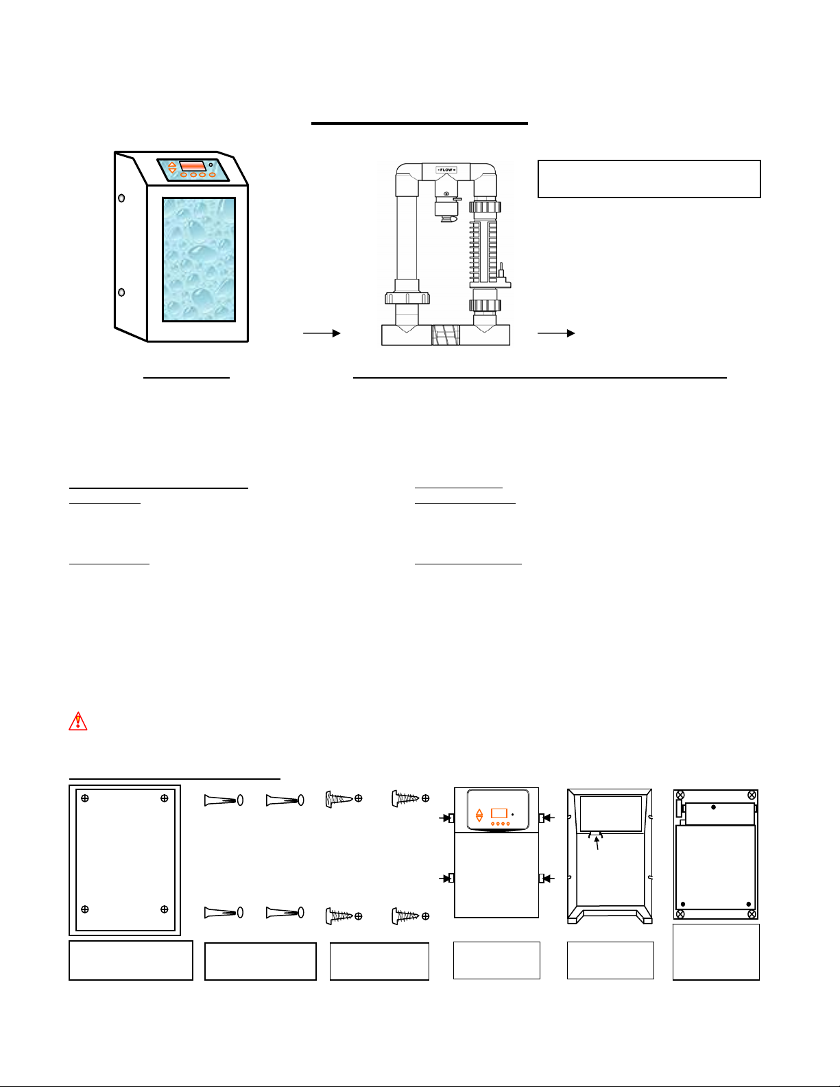
Section 2a – INSTALLATION
g
Main Components
Control Box Patented Automatic Flow Bypass Manifold Assembly
converts incoming AC power to a Low ELECTROLYTIC SUPERCELL TRI-SENSOR ASSEMBLY
Voltage DC current, which energizes the receives Low Voltage DC current from ensures that adequate Flow,
Cell(s). the Power Circuit Board, which initiates Salt Level, and Water
the electrolytic process. Temperatures are satisfactory to
prevent abusive conditions for the
cell to operate.
SPECIFICATION RATINGS: Maximum daily
Input Power: 115 VAC (3.0 AC amps) Cl2 Output Rating: SC-60 1.92 lbs/day (0.88 kg/day)
230 VAC (1.5 AC amps) @ Cell Power 3 SC-48 1.56 lbs/day (0.71 kg/day)
50/60 Hz (8 amps DC) SC-36 1.28 lbs/day (0.58 kg/day)
Output Power: Cell Power 1 (5.0* DC amps) Agency Approvals: NSF, ETLUS, ETLC, CE
Cell Power 2 (6.5* DC amps)
Cell Power 3 (8.0* DC amps) Internal Pump Relay is rated for 30-amp max.
*Indicates nominal amperage output. The dual axis controller will slightly vary the amps to optimize the power to the cell.
12’ (3.6 m) of Cell and Tri-Sensor cords are provided with the unit. Ensure that the manifold is located within that distance
from the control box with enough slack to allow for removal for service or maintenance.
The Digital display provides full information and diagnostics for maintenance and operation of your system. The
programmable settings are retained on a microprocessor chip with the clock setting backed-up with a CR-2025 lithium battery.
CAUTION: To avoid over-saturation conditions of your spa, it is suggested to locate the cell downstream of all other
equipment and on the pool return line only. For applications other than as recommended, contact the factory.
CONTROL BOX INSTALLATION
DRILL ¼” (6mm) DRILL ¼” (6mm)
DRILL ¼” (6mm) DRILL ¼” (6mm)
mounting location. Level,
TOP
TEMPLATE FOR DRILLING
POOL PILOT SOFT TOUC H
& POOL PILOT DIGITAL
MOUNTING HOLES.
DRILL 4 ¼” (6mm) H OLES FOR
WALL ANCHORS WHERE SHOWN.
mark holes and drill.
P/N 18550
BOTTOM
Place Template on
Use the (4) provided
plastic anchors and
insert into drilled holes.
provided screws,
leavin
Tri-Sensor Assembly
Attach the (4)
a ¼” gap.
Super Cell
POOL PILOT
DIGITAL
Loosen four
fastening screws
and lift off cover.
Maximum Operating Pressure: 50 psi
Maximum Flow Rate: 100 gpm
Mount the Control
Disconnect wire
harness.
Box and tighten
the (4) mounting
screws.
4
 Loading...