

Page 1
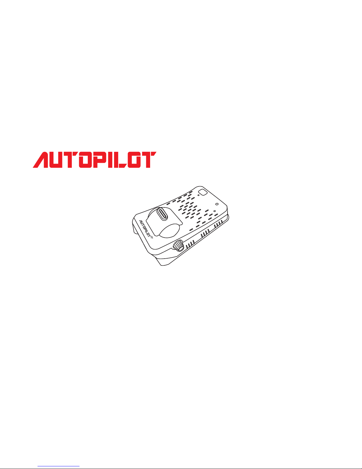
This product is a driving assistance system.
Since any accident while using K15 shall not be the responsibility
of the manufacturer, please drive safely according
to the purpose of this product.
K15
USER’S Manual
Advanced Driving Assistance System
Page 2
TABLE OF CONTENTS
Safety advice
Products and Features
Explanntions of the device
Components
Installation instruction and calibration
Installation location by vehicle type
Features of the product
Setting
Function description
Firmware upgrade
Use for viewer program
3
5
6
7
8
13
17
15
22
26
27
Page 3
Caution
Warning
for potential serious accidents or damages/injuries due to violation of instructions
for potential minor injuries/product damages due to violation of instructions
Install according to the manual. Otherwise the product may not operate or operate properly.
Keep the windshield in front of the lens clean. Foreign substances may cause malfunction
and hinder video input. Keep any objects away from the dashboard as possible.
It may cause reflection on the glass surface which can hinder video input.
Watching the screen while driving can hinder safe driving. Be aware that the user is liable
to accidents and damages.
Apply double-sided tape firmly when installation. Long-hour driving or rocking of the vehicle can
misplace the product which can deteriorate the performance.
Do not put the product in any heating devices(stove, microwave oven, etc.) to dry when it is wet.
It can cause deformation or malfunction for which free services are not available.
Do not use chemical detergents(benzene, thinner, alcohol, etc.) to clean the product.
It can cause fire.
Do not disassemble or apply physical impact. Free services are not available for damages caused
by random disassembly or physical impact.
Cautions are to prevent accidents or danger by using the product safely and properly; therefore please
follow the instructions. The company is not responsible for any problems caused by violation of instructions
in this manual.
Page 4
Caution
Items to check before use
When driving on a road where there is no lane or it is difficult to see the lane
When the lane is not continuous
When GPS reception is not good in a busy city or due to a natural disaster
When the sight is not good due to extreme weather (rain, snow, fog, etc.)
When there are problems with tunnel entrances/exits or the headlights while driving at night
When there is no light or the outside lighting changes abruptly
Abrupt cutting in, changing the lane abruptly
Sharp turn with the radius of curvature less than 250m
Dark tint on the windshield, poor sight due to stickers and accessories
When the vehicle cannot detect the lane if it is driven according to lanes
‘FCWS’ function may not work depending on the color or shape of a car ahead,
brightness of the headlights or whether there are streetlamps
In the condition above, safety assistant systems(LDWS, FCWS) may not work properly therefore drive carefully.
The company is not responsible for any problems caused by violation of instructions in this manual.
Page 5
Products and Features
Safe driving assistance device
Main Features
Forward Collision Warning System(FCWS)
Lane Departure Warning System(LDWS)
Drive Recorder
GPS receiver
Normal, event, manual(forced) recording
Automatic memory managing
It is a cutting-edge product with FCWS, LDWS and Drive Recorder features to deliver essential information
for safe driving.
GPS receiver: It receives GPS signals, sets the operation speed and saves the time and location of the
accident while saving the video.
Page 6
Explanntions of the device
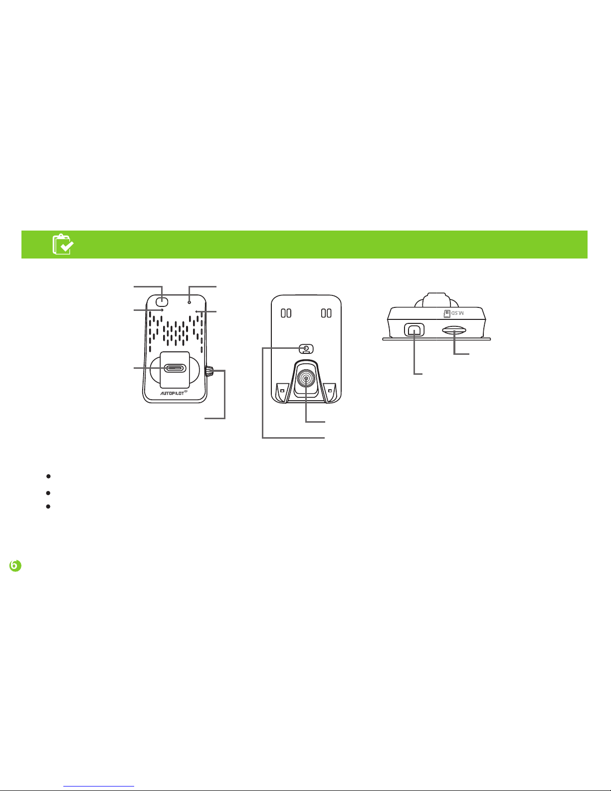
CAMERA LENS
Remote receiver
Angle fix bolt
Angle adjusting lever
Security Warning LED
POWER LED
RESET
MIC
USB type DC input,
Turn signal, Video Out
and GPS connection
Micro SD card slot
When porver is on, LED turns on.
Direction indicator connecting port: Connect the cable that comes with the product.
Angle fix bolt: Adjust angle between the main body and the Lens.
Adjust angle for optimal performance according to car types
(car, SUV, large van, bus, truck).
Page 7
Components
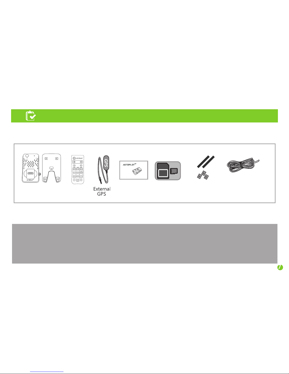
Micro
SD
Adapter
Main device &
Base bracket
Romte
DC(12V~24), GPS,
Turn Signal,
Video Out cable
Micro-SD Card/
Adapter
Double-sided
tape / Cable
Mount
Manual
Check whether all components are included as shown above after purchasing the product.
Contact the store of your purchase if any component is damaged or does not perform properly.
Components above are subject to change for better performance.
(Images above are to help consumers with understanding the product and may be different from
the actual product.)
K15
USER’S Manual
Advanced Driving Assistance System
Page 8
Installation instruction and calibration
Make sure to keep the following in mind before installation.
• Installation shall be made on even flat ground with the car engine turned off.
• Please check the necessary components enclosed in the product kit and follow the installation
instruction step by step.
• This manual describes how to install K15 in a car by car type: passenger car, SUV, Bus and truck.
For buses and trucks, except for the installation position, the procedures are similar with those
for passenger cars. You can find details later in this manual.
• After successfully installing the camera, drive on a even, straight road to receive GPS signals
(this will take up to 5 minutes). When you drive over 30 mph, you will hear a recorded voice
“The Land Departure Warning System has been calibrated.” In re-calibrations another voice
message explains “Recalibration has started.” After the voice messages all functions will
normally operate.
• If K15 performs incorrectly please reinstall it according to the installation instruction.
Page 9
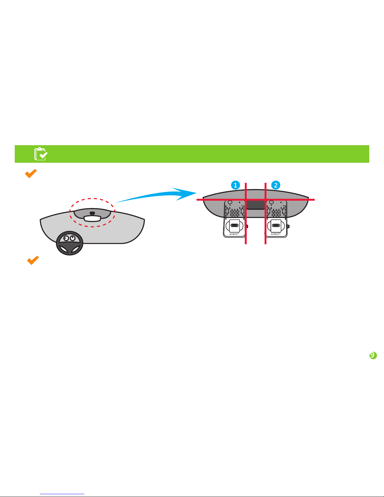
Installation (how to attach/where to attach/angle) for passenger cars and SUVs
For perfect installation of K15 please make sure to follow the details of this manual step by step.
Install this product with the car’s engine turned off.
1. Apply the double-sided
tape enclosed in the package
and peel the film of the tape off.
Installation instruction and calibration
5. Arrange the power cord neatly
alongside of the windshield and
door pillar trim. Use the provided
wire splice clips.
6. Connect the power cable
to the main body.
7. When connecting the turn signal
cable or video out cable,
use the nearest connector or please
refer to page 12 in USER’S Manual.
Installation (example for passenger car, SUV & Large SUV.)
Horizontal
Vertical
2. Stick the base bracket on
the windshield #1 or
#2 position
4. Stick the GPS sensor
on the top of
the windshield.
3. Put main device
into the base
bracket
Page 10

Installation instruction and calibration
After checking the GPS reception, follow the step 7.
Fix the bracket horizontally with the front windshield.
Fix the main body with the angle adjusting bolt horizontally with the ground.
Installation
8. It needs to connect the monitor screen to get video-out from the device, a yellow horizontal line appears on it.
Refer to the pictures below for indoor and outdoor installation, respectively.
Indoor installation: As shown in the picture, place the product so that the blue line on
the monitor is placed at the point where the virtual red lines cross and fix it with
the angle adjusting bolt.
Outdoor installation: First park the car in an even, open place with no big obstacles such as tall buildings.
As shown in the picture, place the product so that the blue line on the monitor is placed on the horizontal
line (the point where the virtual red lines cross) and fix it with the angle adjusting bolt.
Horizontal Line
Artificial Line
Page 11
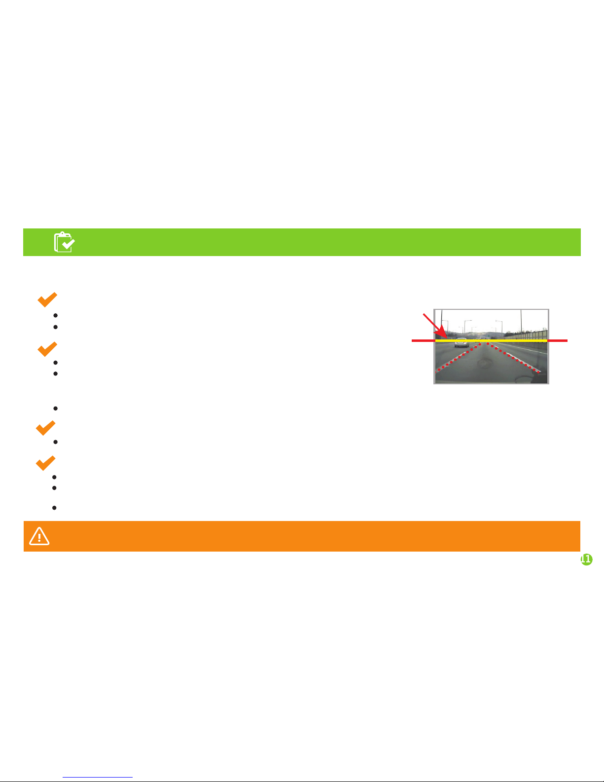
Installation instruction and calibration
Caution
Reset calibration when the main body angle is altered or the car model is changed due to car replacement.
Reset calibration when LDWS/FCWS alert doesn’t work properly.
9. When the previous steps are completed, power up the engine to provide power to the product.
Check if the monitor connected for video-out function is normally working.
Virtual line
Calibration lines
Horizon
Horizon and yellow
Calibration lines match
Step 1: Selecting car model
Select car model.
Car models: car, SUV, large van, bus (see page 17 in the manual)
Step 2: Adjust horizontal and calibration line
Park the vehicle in a place with open front space and flat ground.
Match the horizontal line(where the red dotted lines meet)
to the yellow calibration line marked on the monitor and fix
the angle adjusting bolt firmly.
Calibration line is visible only when setting calibration(LDWS initialization).
Step 3: GPS reception
Audio guide is on when GPS reception is complete.
Step 4: Position adjustment (calibration)
When audio guide informs completion of GPS reception, start operation for calibration.
Audio guide will inform that calibration is complete after driving for 1~3 minute over 30mph on a straight
road with a single fine line on both sides.
All functions work normal after the audio guide
Page 12
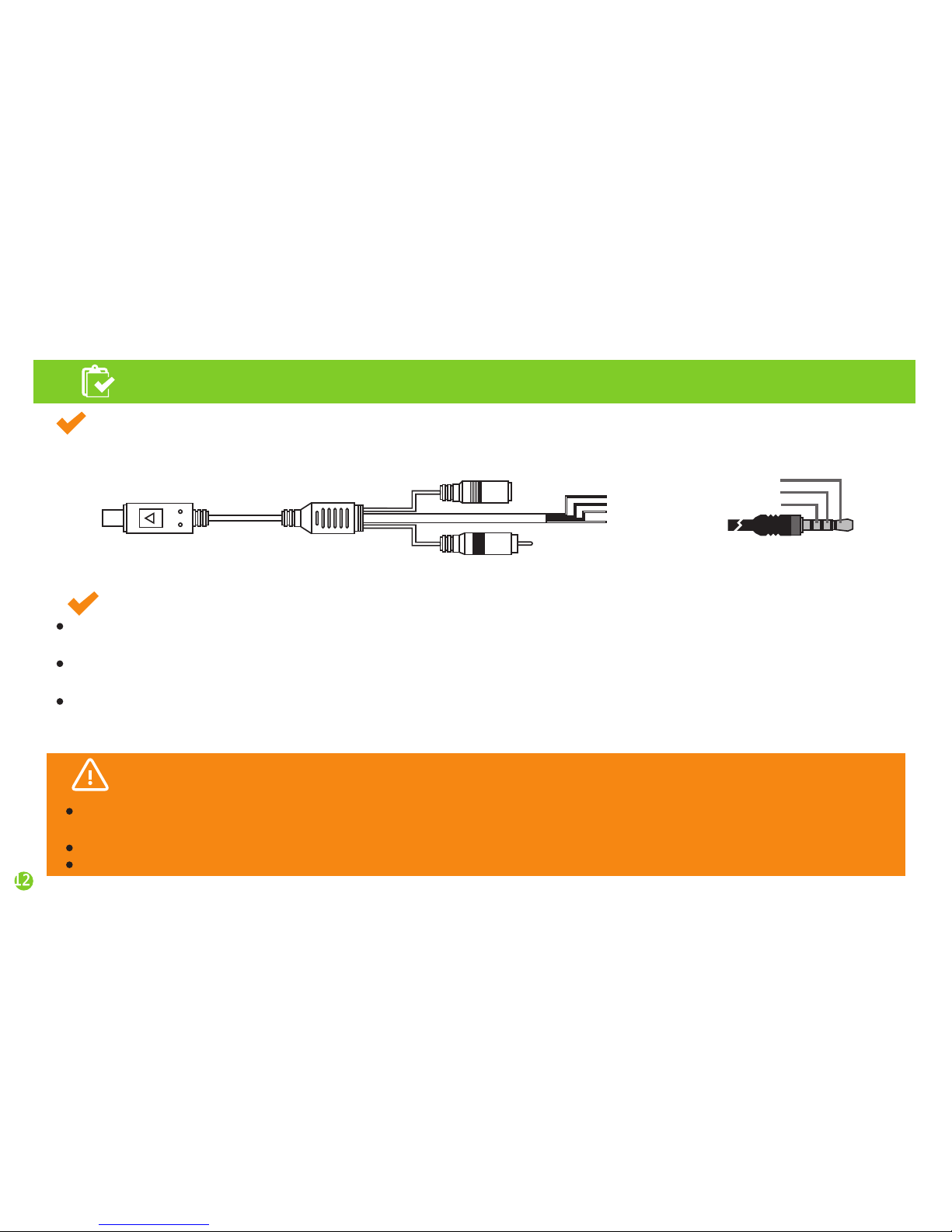
Installation instruction and calibration
Installation instruction for the DC Input cable, the turn signal cable and video out cable
Check ‘T/C connection’ when connecting the main body during installation of the direction indicator
cable(T/C) to a vehicle.
Connecting to a wrong location can cause serious damage to the product. Please check for the right location.
The company is not responsible for any damage to the product due to violation of the instructions.
How to connect direction indicator cable
When the direction indicator is connected with the cable, the alert won’t go off when changing the lane
with the indicator light turned on.
The lines are red, white, yellow and black, all of which should be connected with the signal lines connected to
the direction indicator light when setting the direction.
Direction indicator light cable signal lines are usually under the wheel; connect the Red one to the ACC ,
the black one to the GND and white/yellow one to either left/right direction indicator light signal line.
Use the closest location if it’s difficult to connect.
Warning
The following cases may cause serious damage to the product due to violation of
the instructions:
USB Type Connect
GPS Connect
Video Out Connect
Red : ACC
White : T/C Left
Yellow : T/C Right
Black : GND
GPS
connecting cable
GND
TXD
VCC
Page 13
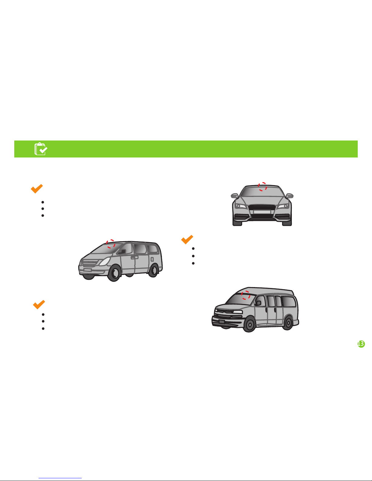
Installation Position
Installation Position
Installation Position
Installation location by vehicle type
Passenger car
4 car types are available for installation.
Install the product in top center of the windshield.
Make sure the product is aligned horizontally.
Select car mode: Sedan
SUV, mini van, small truck
Install the product in top center of the windshield.
Make sure the product is aligned horizontally.
Select car mode: SUV
Large SUV, large van
Install the product in top center of the windshield.
Make sure the product is aligned horizontally.
Select car mode: large van
Page 14

Installation location by vehicle type
10cm
10cm
Installation Position
Installation Position
Bus :
Attach the bracket on the front window within
10cm from the vertical line, which is typically placed
on the center of the front window and 10cm above the wipers
so as not for them to disturb the field of vision of K15. Arrange
the cables neatly using the provided wire splice clips.
Truck :
Attach the bracket on the center of the front windshield about 10cm
above the wipers and arrange the cables neatly with the provided
wire splice clips so as not to disturb the field of vision of the driver.
K15 can be operable in the voltage range of DC 12V to 24V but it doesn’t necessarily mean that the product can
operates in all buses and trucks. Please ask advice from the store where you bought your K15 for the use
in a truck or a bus. Any damage or malfunction caused by power problems of the product installed in a truck
or bus shall not be the responsibility of the manufacturer.
For trucks and buses, do not forget to install a power stabilization cable (a 24V to 12V adapter).
Caution
Page 15
Features of the product
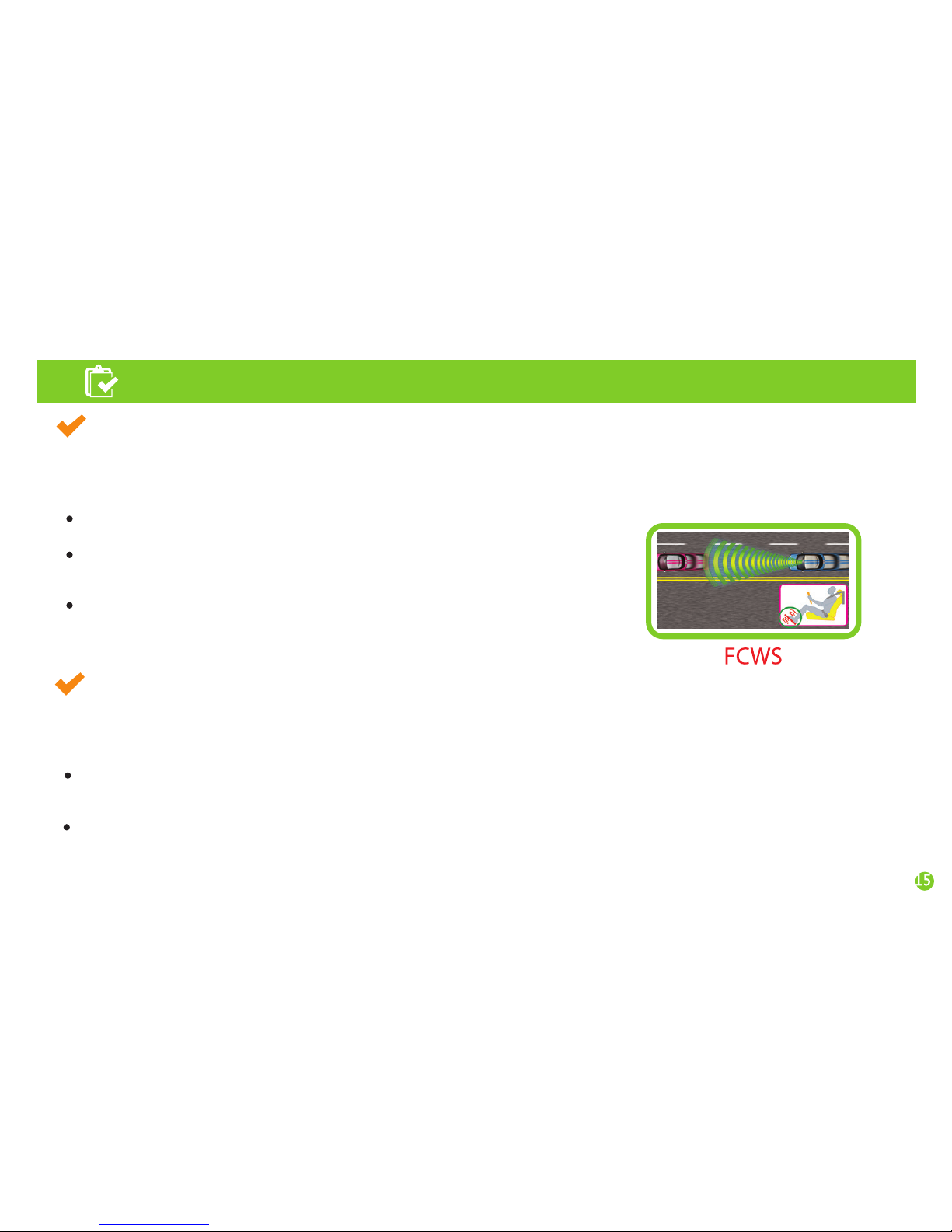
FCWS(Forward Collision Warning System)
K15 is a driving assistance device that detects forward collision and lane deviation risks by obtaining the image
of the road in front of the car through its internal camera and analyzing the data real time, and gives warnings
to prevent any possible accident that can be caused by the driver’s reckless or drowsy driving.
When there is a risk of a collision with the car in front,
K15 gives a warning to the driver in advance.
Time To Collision (TTC) function: With the TTC function on,
K15 predicts the time of a collision in advance and sounds an alarm
when the time comes. It works only when the car speed is over 30 km/h.
FCW(Forward Collision Warning) function : K15 gives a warning
when a sudden collision risk occurs.
LDWS(Lane Departure Warning System)
K15 is a driving assistance device that detects forward collision and lane deviation risks by obtaining the image
of the road in front of the car through its internal camera and analyzing the data real time, and gives warnings
to prevent any possible accident that can be caused by the driver’s reckless or drowsy driving.
With the VIDEO OUT mode on, you can monitor the video image of an LDWS situation on a TV screen or
a navigation system. But for safe driving, please use the Video-out function only when necessary.
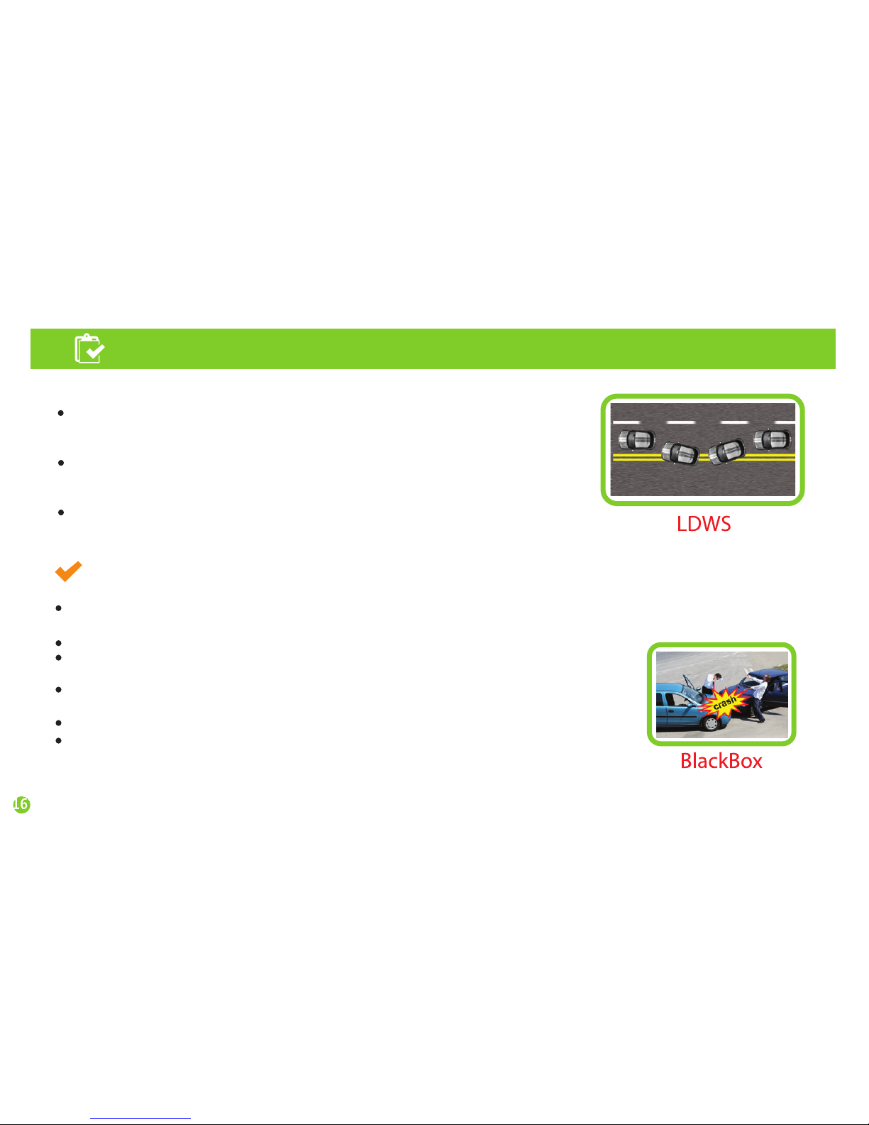
K15 gives the driver the information about lane departure situations
(, which will help enhance the driver’s alertness and ability to handle a crisis).
Page 16
Features of the product
Drive Recorder
After K15 booted up, when an internal G-sensor (a shock-detection sensor) detects an event,
K15 automatically records the image for 40 seconds.
K15 also records the time and location of an event as well as the image.
Regardless of the amount of force imposed on the car, you can record the image
by pressing the recording button
During driving, K15 constantly records the image at any event and the driver
can check it through a viewer program.
K15 has a Micro SD card slot (the memory is flexible on your choice).
K15 support a PC viewer program so that you can check the recorded images
on a desktop or a laptop.
K15 gives warnings in the case of continuous lane departures
(when the car deviates from its lane repeatedly without indication).
The driver can set his/her own timing of an alarm
(five levels for left and right lines, respectively)
With the turn signal cable connected, there is no LDWS alarm during turn signals
Page 17
Setting
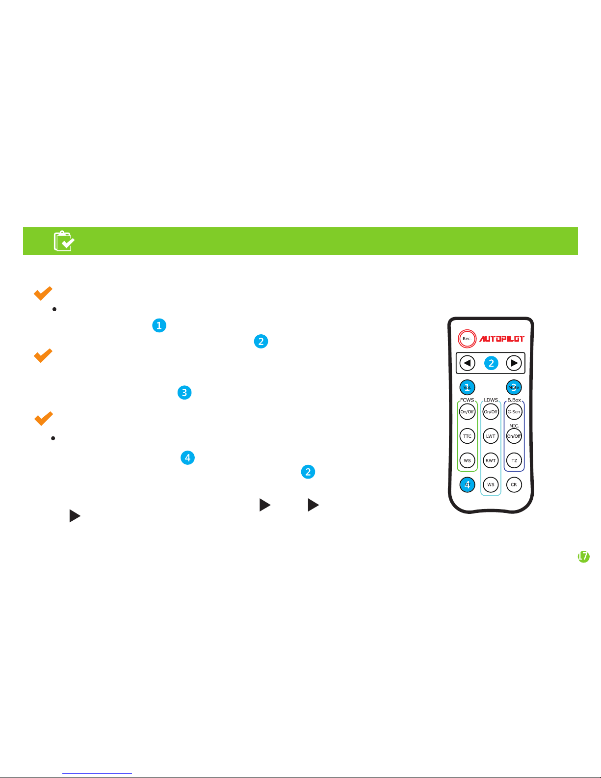
You can set all the functions and modes of K15 with the remote control enclosed in the package.
CT(Car Type) : Type of the car where this product will be installed.
How to set the CT :
1.
Press the CT button(CT)
A voice message will say “Car type.”
2.
Choose your car type by pressing the arrow button
Every the button is pushed, recorded voice will tell
you a car type as follows: “passenger car”
“SUV” “large SUV or VAN”
Repeatedly press the button until you hear your car type.
When you stop pressing, car type is automatically set.
1.
This button is to activate/deactivate alarm sounds and voice instruction.
When you press button
MUTE: Remove the voice instruction.
VOL: Volume control
How to control volume :
( Arrow key)
1
. Press Vol. button You will hear a voice “volume control mode”.
2.
You can control the volume with button.
“bus or truck”.
recorded voice explains “sound has removed”
or “sound has been activated”.
Page 18
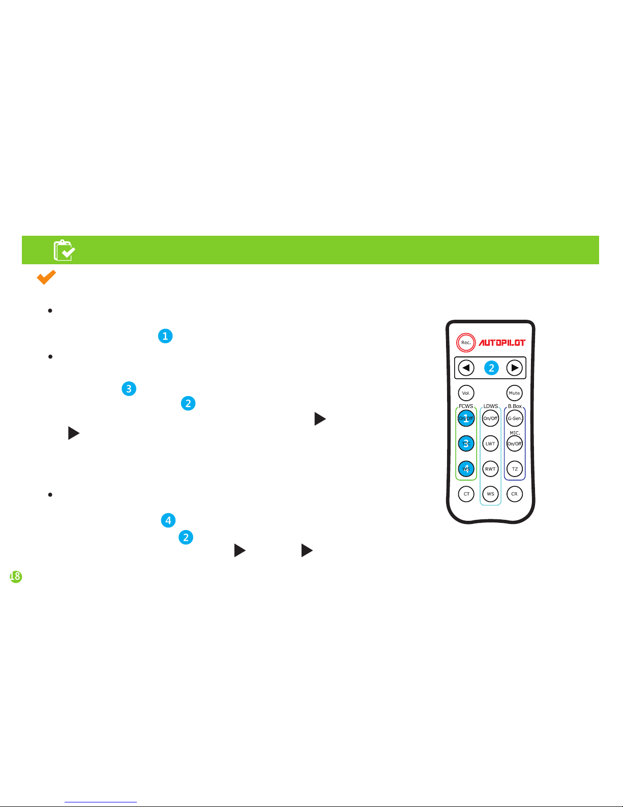
If K15 operates incorrectly while FCWS, you can start
by pressing button You will hear “FCWS On/Off”.
FCWS On/Off :
Setting
1.
This is to calculate predicted time to collision and give an alarm in advance.
Press button
2.
Adjust the time the button Every time the button is pressed,
the voice message changes as follows: “half a second” “one second”
“one and a half seconds”.
If you set the time as 1.5 seconds, an collision alarm will sound at
a relatively longer distance. A predicted distance to a collision
can vary according to the car’s speed.
TTC (Time To Collision) :
WS(Working Speed) :
1.
This button is to set the working speed of Forward Collision Warning
unction. Press button then recorded voice says “working speed setting”.
2.
Set the speed with button Every time the button is pressed the voice
message changes as follows: “10mph” “20mph” “30mph”.
FCWS
2
the you will hear “time to collision setting”.
Page 19
Setting
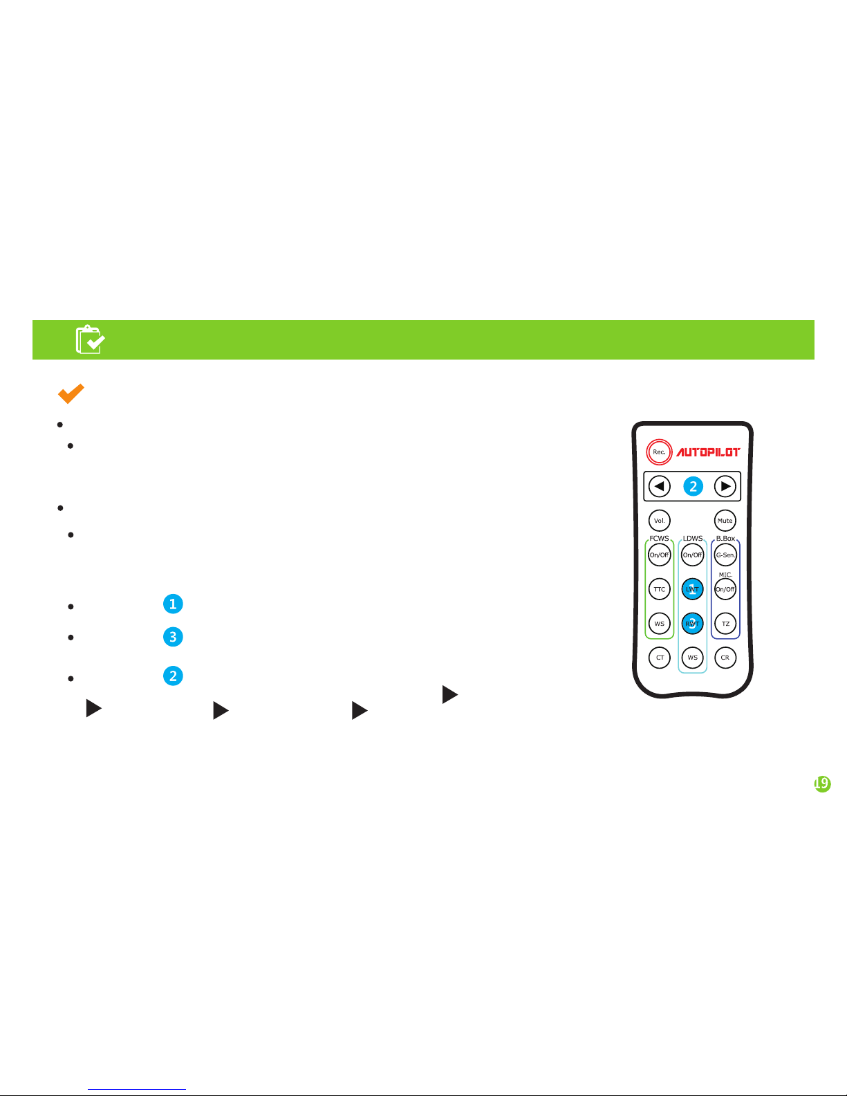
This is to set the timing of an alarm for a left line deviation.
If you feel that the timing of the alarm is too fast or late, you can change
the alarm timing for every 10cm.
Press button then you will hear “left line alarm timing”.
Press button Every time the button is pressed you will hear
the voice message changes as follow: “level two faster” “level one faster”
“nominal mode” “level one faster” “level two slower”.
When you hear a message you want, stop pressing and wait for a moment.
LWT(Left Warning Time) : alarm timing for left line deviation
LDWS
RWT(Right Warning Time) : alarm timing for right line deviation
This is to set the timing of an alarm for a right line deviation.
If you feel that the timing of the alarm is too fast or late, you can change the
alarm timing for every 10cm.
Press button then you will hear “right line alarm timing”.
Page 20
Setting
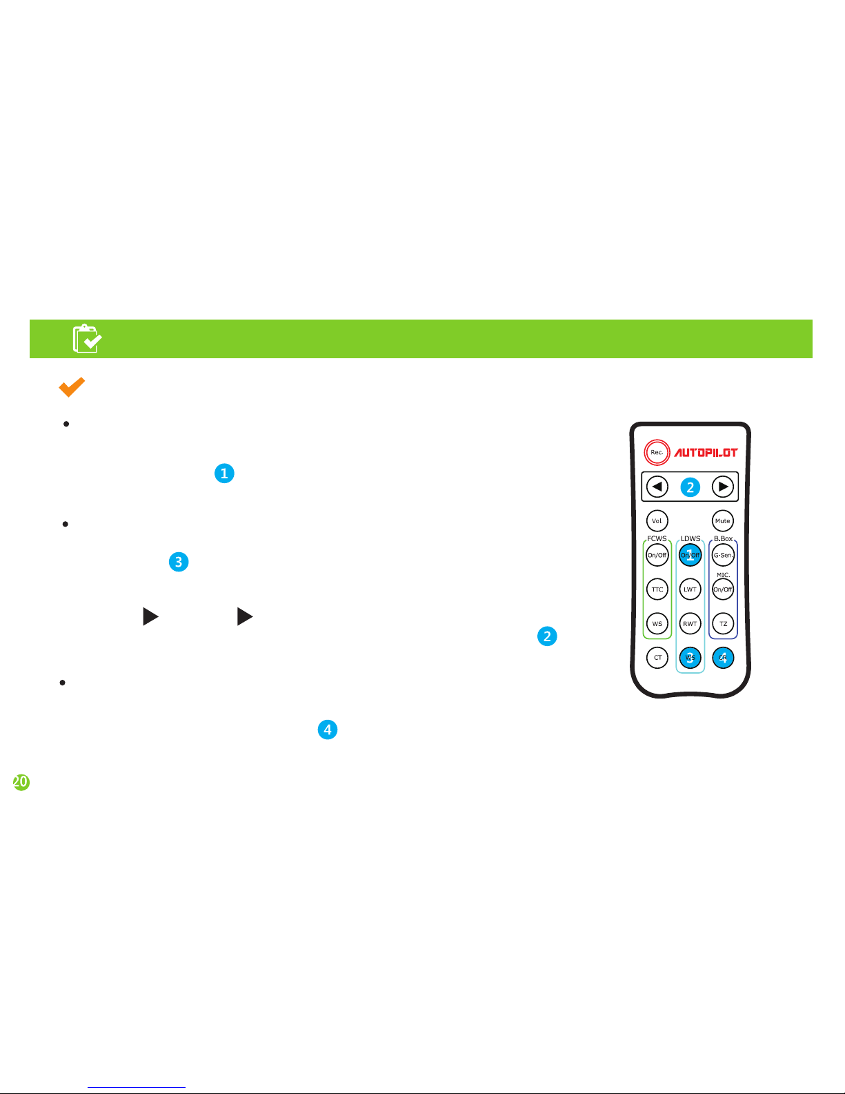
LDWS
If K15 operates incorrectly while LDWS, you can start
by pressing button You will hear “LDWS On/Off”.
LDWS On/Off :
1. If K15 operates incorrectly while FCWS and LDWS, you can start
recalibration by pressing button You will hear “calibration reset”.
CR(Calibration Reset) :
WS(Working Speed) :
This is to set the working speed of Lane Departure Warning
Press button then recorded voice says “working speed setting”.
Set the speed with button
Every time the button is pressed the voice message changes as follows:
“35mph” “45mph” “55mph”. Stop pressing when you hear
the speed you want and wait for a moment it is automatically set.
Page 21
Setting
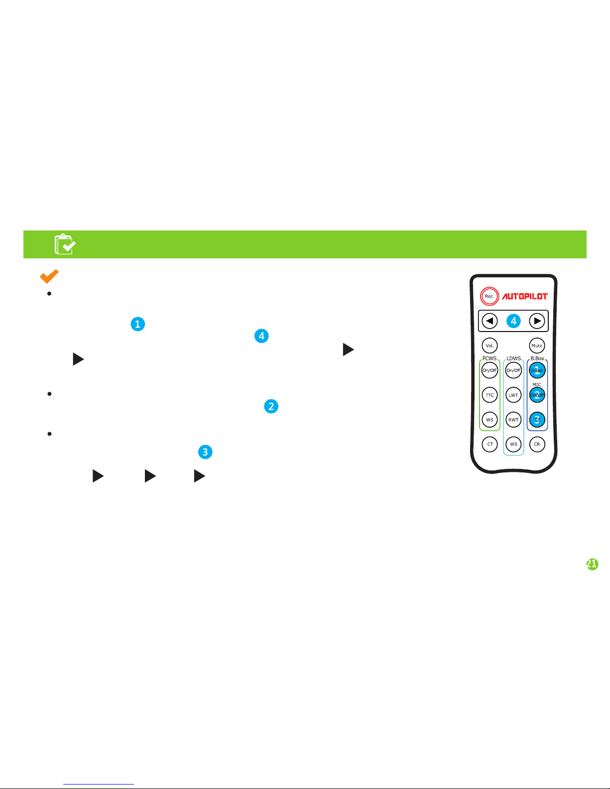
G-Sen(G-sensor shock):
MIC. On/Off :
This is to set the Voice recorded On/Off.
1. This is to set the impact level that a G-sensor installed in K15 detects.
Press button then you will hear “impact level setting”.
2. You can change the setting with button Every time the button is pressed,
the voice message changes as follows: “sensitive detection” “normal detection”
“insensitive detection”. Stop pressing when you hear the mode you want.
If you think K15 records impacts too often set the mode as “insensitive detection”.
1. This is to set the Time zone.
“PST” “MST” “CST” “EST”
TZ(Time Zone) : Your Position Form the satellite.
B.Box
PST : Pacific Time Zone
MST : Mauntain Time Zone
CST : Central Time Zone
EST : Easten Time Zone
Page 22
Function description
Once the car engine started, K15 is provided with power and red and blue LEDs are on.
→ Make sure that K15 is connected with the provided power cable.
After booting, K15 starts operating with the recorded message.
Function description
Manual recording
Briefly press the REC button to start manual recording. The red LED will keep blinking until the recorded
video file is stored.
The file is stored in the “EVENT” folder in the Micro SD card.
If you want to extend manual recording time, briefly press the REC button after the previous recorded
file is stored. Then another 40-second video will be stored continuously.
Continuous recording
In this mode, once power on, K15 keeps recording and the files are stored in the “NORMAL”
folder in the Micro SD card.
Page 23
Function description
Caution!
Even in a same mode, the sensitivity can vary according to the car type, car conditions,
and the car’s ability to absorb an impact. Since event detection relates to a physical amount of an impact
that the product can detects, the sensitivity cannot be set according to the driver’s feeling.
When event recording doesn’t operate correctly, the manufacturer does not hold any responsibility except for repair.
Event recording
Event recording records the images of an impact (for 40 seconds) that the internal G-sensor detects and
stores the recorded file as “*.avi” format.
The file is stored in the “EVENT” folder in the Micro SD card.
In event recording, sensitivity of the G-sensor can be set as three levels – sensitive, normal, and insensitive.
Every time the G button is pressed, the voice message changes as follows: “sensitive detection”
“normal detection” “insensitive detection”. Stop pressing the button when you hear the mode you want
and wait until it is automatically set.
Page 24
Function description
Video-out and turn signal connection (the cable can be offered at a cost.)
With the Video-out function, you can check video images real time on a screen device by connecting K15
USB port and the import port of the screen via the Video-out cable additionally provided on your option.
The provided Video- out cable is RCA type (male). It can be connected to a AV-IN RCA port of a screen device.
The turn signal connection cable is all-in-one with Video-out cable. The turn signal cable comprises three lines.
Connect them with the signal lines (12V), which are normally placed under the driver’s seat.
Connect the black line with Ground and the rest two lines with the signal lines, respectively.
Once the turn signal cable is connected, in the LDWS mode when you change the lane with the direction
indicator on, an alarm does not sound.
RED LEDs on:
After booting, all functions (constant/event/manual recording) are normally operable.
After working, RED LED is blinking slowly
LED operation measure
Page 25
Caution!
Since K15 keeps operating once power is supplied,
injection or ejection of the Micro SD card during operation
can cause damage to the system and the memory card.
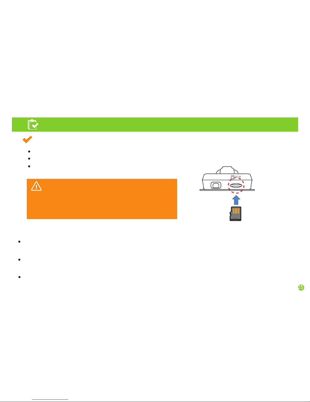
Insert the Micro SD card with its logo side toward the rear case of K15.
Plug out the SD card, slightly press it.
For details, see the picture below.
Plug in & out Micro SD card
Never inject/eject the Micro SD card
while power on.
Micro-SD
K15 receives GPS time data in regular interval and synchronize its time with the received time in order
to record exact time of any event. Therefore, once time is set, the RTC function makes K15 work in accordance
real time.
Automatic time setting: After booting, when the car is in a place where GPS reception is possible
(for at least 5 minutes for the first use), K15 automatically synchronizes its system time to the received
GPS time data.
Since then, time will be automatically set once every day.
Function description
Page 26
Firmware upgrade
(1) Do not turn the power OFF during firmware upgrade. It may damage the system.
(2) If normal booting during upgrade or normal upgrade doesn’t work, format Micro-SD card and reinstall.
Read the followings carefully before upgrade. (contact the stores for upgrade files.)
- Step 1: Copy the upgrade files onto the root directory of Micro-SD card.
- Step 2: Turn the power OFF and insert Micro-SD card.
- Step 3: Connect the power cable to the main body and turn the power ON.
- Step 4: Wait for about 10~20 sec.
- Step 5: Start upgrade once the power LED(red LED)
- Step 6: It automatically restarts after finishing
upgrade.
- Once firmware upgrade is done, all settings are
initialized.
- Make calibration for setting FCWS and LDWS.
(page 11)
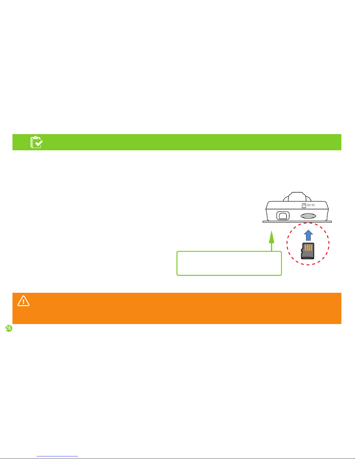
Micro SD Card
Caution
* Insert Micro-SD card with
the printed side toward the lens.
Page 27
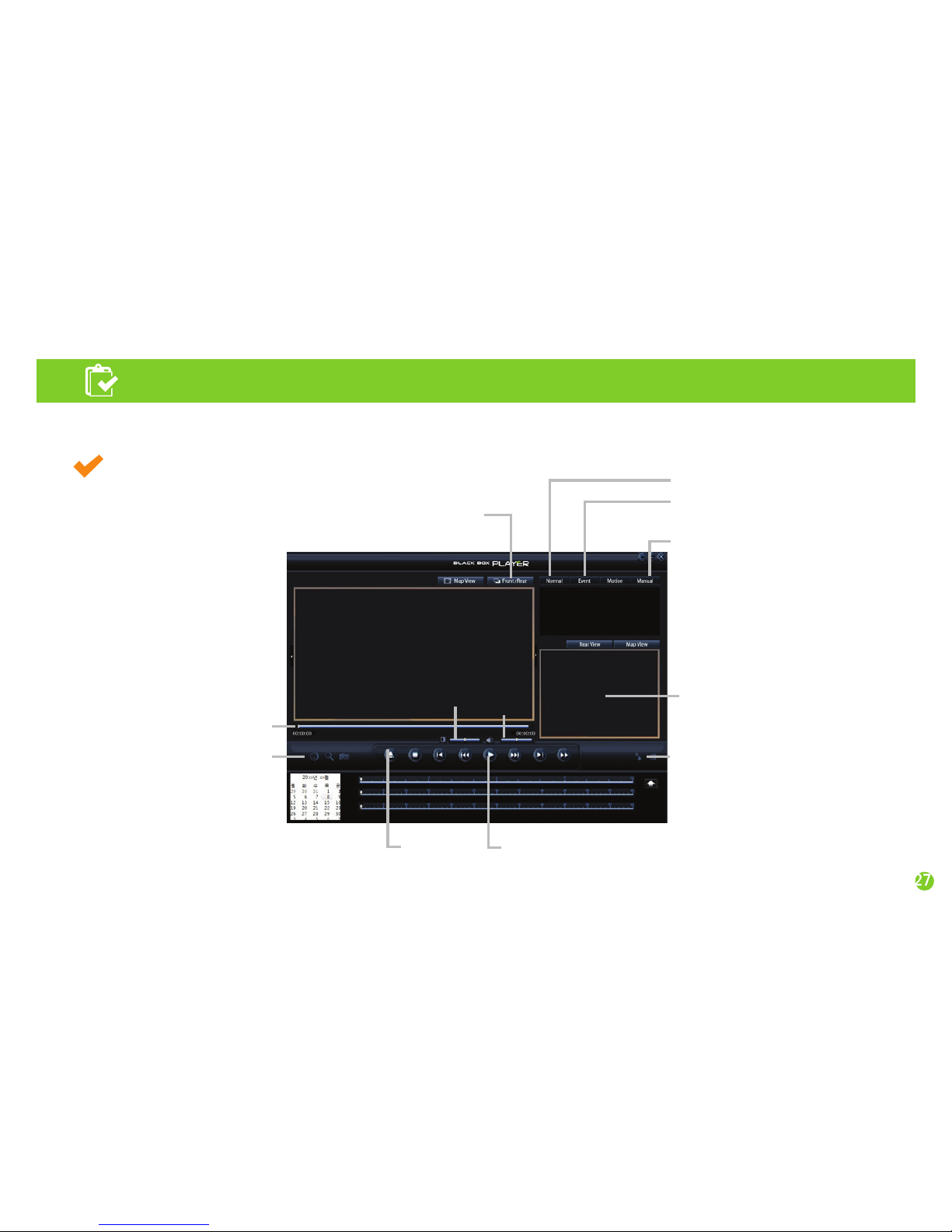
PC viewer screen
Select front/rear video
Select normal recording
Select impact recording
Select forced(manual) recording
Viewer program (PC Viewer)
Run BlackBox viewer installation file in Micro-SD card and install by following the instructions.
When installation is complete, click on the Open icon to open the viewer program.
Front video
Screen brightness
control
Volume
Open files
Switch top/bottom, left/right
Play
Video data timeline
Accelerating sensor
Enlarge screen
Screen capture
Map
Page 28
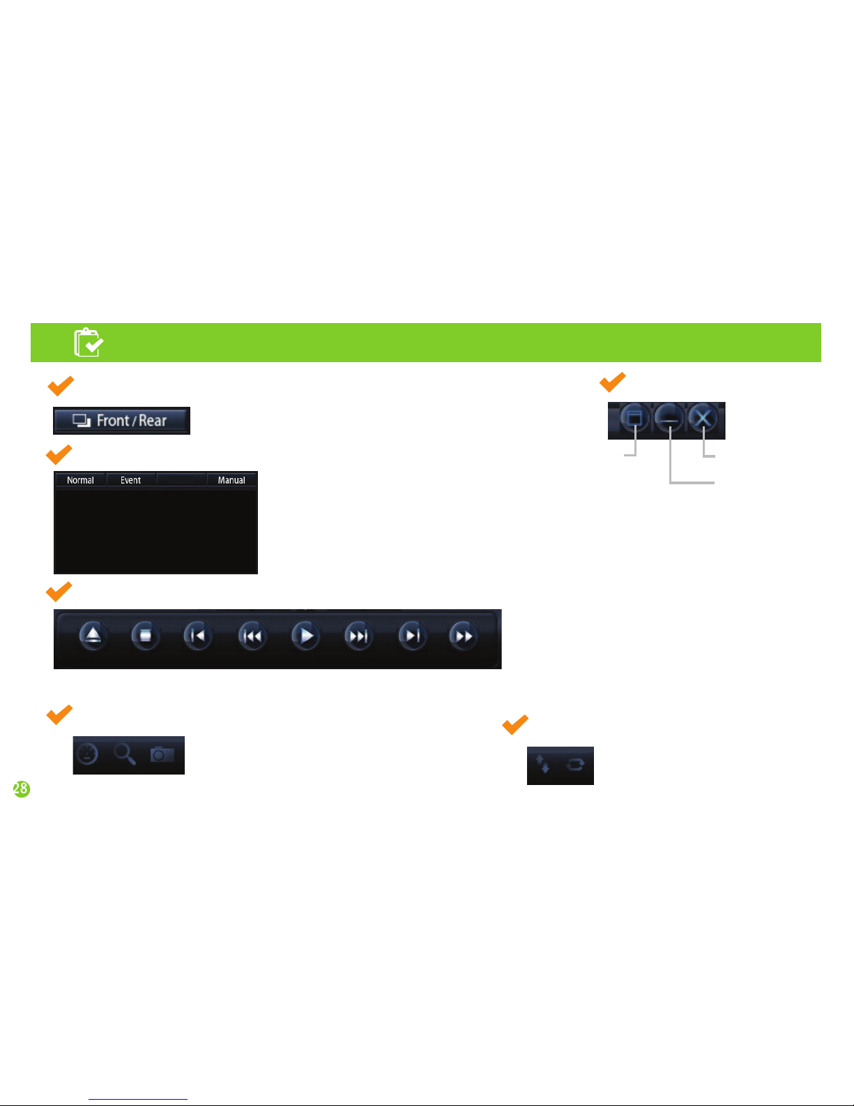
Viewer program (PC Viewer)
Switch Front/Rear
Switch windows
20140001 0231_M_001.avi
20140002 0232_M_002.avi
20140003 0233_M_003.avi
20140004 0234_M_004.avi
Switches front/rear and plays the video.
Maximize
the screen size
Minimize
the screen size
Close program
Select video folder to save
Play control buttons
Play control button
Top, bottom, left and right button
Nomal : Normal recording video list
Accelerating sensor: Displays accelerating
sensor graph.
Enlarge screen: Enlarges the screen size.
Screen capture: Saves videos in images.
Switches top/bottom/left/right
of the videos.
Event : Impact recording video list
Manual : Manual(forced) recording video list
Open the folder, select the file and press Play button to play the video.
Import Stop
Previous
file
Rewind Play Fast
forward
Next file
View
by frame
Page 29

MEMO
Page 30

MEMO
Page 31

MEMO
Page 32

Specifications
Model
Main features
Capacity
Camera
Operation/storing
temperature
FCWS, LDWS, Drive Recorder
Micro SDHC Class10 (supports up to 32GB)
2M HD 1280 x 720
GPS External GPS
Operating volt. DC 12V ~ 24V
32℉ ~ 140℉ / 14℉ ~ 158℉
K15
 Loading...