

Page 1
APE4200
USER MANUAL
ECLIPSE F90 (Master Environmental Controller)
AutopilotControllers.com
Page 2

AutopilotControllers.com
2
Page 3

TABLE OF CONTENTS
OVERVIEW 4
PARTS LIST WHAT’S IN THE BOX 5
LED DISPLAY & CONTROL SURFACE 6
OPERATING INSTRUCTIONS 7
CO2 PPM SETTINGS 7
CO2 & TEMP LOCK/UNLOCK SWITCH 7
TEMPERATURE SETTINGS 7
HUMIDITY & TEMPERATURE RH% & TEMP LOCK/UNLOCK SWITCH 7
HUMIDITY SETTINGS 8
HUMIDITY DEADBAND HYSTERESIS 8
HUMIDITY MIN/MAX RECALL 8
HUMIDITY MODE SWITCH 8
TEMP DEADBAND OPTIONS 8
TEMP DEADBAND SETTING 8
CO2 MODE 8
HIGH TEMPERATURE PROTECTION 8
HOW TO SET HIGH TEMP LIMIT 8
DAYTIME MODE LED/ERROR LEDS/ERROR DISPLAY MESSAGES 9
SPECIFICATIONS 9
MOUNTING INSTRUCTIONS 10
MOUNTING THE UNIT TO A WALL 10
MOUNTING THE UNIT TO A GROW TENT 10
GENERAL WARNINGS 11
SULFUR VAPORIZER WARNING 11
WARRANTY 12
3
Page 4
Thank you for purchasing the Autopilot ECLIPSE F90 (APE4200) Master Environmental Controller.
The ECLIPSE F90 offers integrated digital command of critical grow room conditions. Autopilot takes
full atmospheric control and lets you get back to growing. The F90 precisely controls temperature,
humidity, and CO
2
PPM levels in the growing area. Its three large LED displays make monitoring
and adjusting these environmental conditions a breeze. Three screens continuously display current
temperature, humidity and CO
2
PPM levels, and its LED lights indicate active modes and inform the
user of any errors. The ECLIPSE F90 Master Environmental Controller is easy to program and operate
while showcasing total transparency of environmental conditions 24 hours a day.
The ECLIPSE F90’s enclosure features four separate power outlets for external control of cooling (AC
or exhaust fan), heating, CO
2
(regulator or generator), and humidity (humidifier or dehumidifier).
These outlets feature heavy duty protective covers that prevent atmospheric moisture from
entering the device through any unused outlets. Rubber feet have also been added to the back of
the unit for added protection when mounted.
This controller’s sensitive and intelligent remote combination probe features a highly accurate dual
beam NDIR CO
2
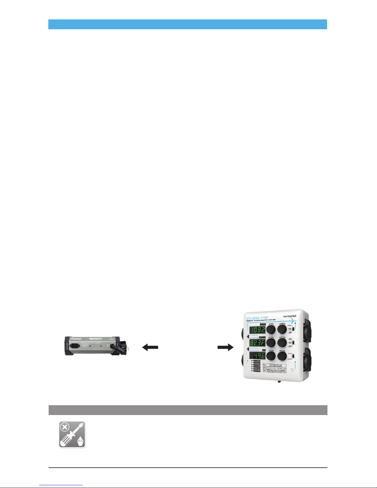
sensor. The probe can be placed up to 15 feet from the controller, and has been
designed to resist EMI/EFI from electronic ballasts. The controller itself comes equipped with wall
anchors and optional U-brackets for tent mounting.
Each ECLIPSE F90 has been pre-programmed with factory recommended settings for quick plug
and play operation. Humidity deadband, for example, is preset to 5% +/-. An adjustable Fuzzy Logic
setting is also available for use with CO
2
tank and regulator systems.
For information on additional Autopilot products please visit AutopilotControllers.com.
NOTE: After turning on the power to the unit, it will take five minutes for the sensor to warm up.
NOTE: This controller has a 14.5A maximum load. For higher amperage devices such as A/C units, it is
recommended to use a power expander.
OVERVIEW
TOOLS NEEDED - (FOR OPTIONAL MOUNTING)
Phillips
Screwdriver
8' (2.5 m)
minimum
4
Page 5
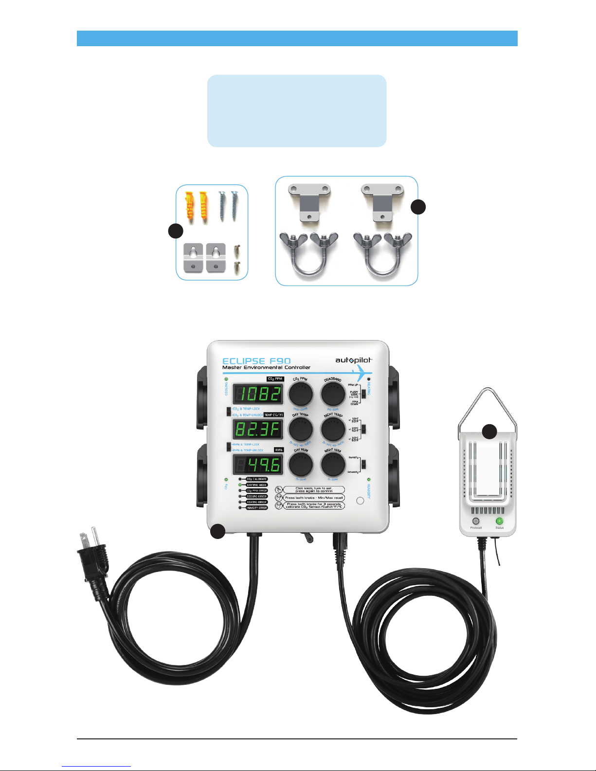
PARTS LIST (WHAT’S IN THE BOX)
A
B
A - Controller Unit
B - Sensor Unit
C - Mounting Hardware (for walls)
D - Mounting Hardware (for grow tents)
D
C
5
Page 6
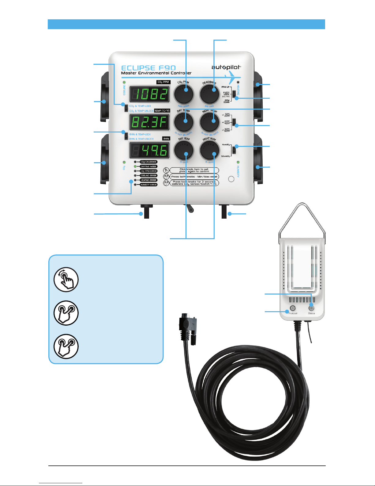
FUNCTION KNOBS
LED DISPLAY & CONTROL SURFACE
(
CO2 & TEMP LOCK
)
(
HUM & TEMP LOCK
)
(
ERROR LEDS
)
(
CO2 PPM SETTING
) (
CO2 DEADBAND
)
(
HUMIDITY SETTING
)
(
HUMIDITY MODE
)
(
CO2 MODE
)
(
HEATING OUTPUT
)
(
COOLING OUTPUT
)
(
CO2 OUTPUT
)
(
HUMIDITY OUTPUT
)
(
TEMP DEADBAND
)
(
TEMP SETTING
)
Click (press) knob, turn to
set, click again to confirm
Press both function knobs
for Min/Max recall
Press both knobs for 3
seconds to calibrate CO
2
Sensor/Switch F°/C°
(
PHOTOCELL
)
(
STATUS
)
(
POWER INPUT
)
(
SENSOR CORD
)
6
Page 7

OPERATING INSTRUCTIONS
CO2 PPM SETTINGS
CO2 LEVELS: Click the CO2 PPM knob and turn to set the PPM target. Click again to confirm the
setting.
CO
2
DEADBAND: Click the DEADBAND knob and turn to set the desired deadband setting. Click
again to confirm the setting.
Example: For CO
2
increase mode, if setpoint=1000 PPM and deadband=50 PPM, the CO2 output will
start to work at or below 1000 and turn off at 1050 PPM. For CO
2
decrease mode, the fan will start at
or above 1000 PPM and turn off at 950 PPM.
MIN/MAX RECALL: Click and hold the CO
2
PPM and DEADBAND knobs simultaneously to display
the CO
2
min/max PPM record. The display will show L XXX, H XXX. The screen will return to normal
display after 5 seconds (or immediately if you click both knobs simultaneously again), and the
record will be reset.
CALIBRATION: Place the CO
2
sensor outdoors, press both knobs for 3 seconds, display screen reads
CAL/400, if you need to change the calibration level, turn the left knob. Keep the sensor from direct
sunlight and any breathing. Allow it 10 minutes to stabilize the PPM reading. The Screen will return
to normal display once the calibration is complete.
CO2 & TEMP LOCK/UNLOCK SWITCH
LOCK: This setting will not allow the CO2 and Temp outlets to run simultaneously. The CO2 outlet
will always be deactivated when the Cooling outlet is activated On. Lock setting is recommended
for rooms applying CO
2
that are also operating an exhaust fan for temperature control. This setting
minimizes CO
2
loss when the exhaust fan is operating.
UNLOCK: The CO
2
enrichment device and any cooling device that is plugged in are independently
controlled.
TEMPERATURE SETTINGS
The unit offers both day and night temperature control. Select either the heating or cooling mode
option.
DAY TEMP SETTING: There is a Day Cooling set point and a Day Heating set point.
1. To set the Day Cooling, Click the DAY TEMP knob. “COOL” will be displayed. To change the
setting, turn the DAY TEMP knob to select your desired temperature. Click again to accept the
new setting.
2. “HEAT” will then be displayed. Turn the DAY TEMP knob to select your desired setting, then click
the knob again to save the new setting.
NIGHT TEMP SETTING: Night temps are set exactly the same way as described above for day
temps, but using the NIGHT TEMP knob this time.
TEMP MIN/MAX RECALL: Press the DAY TEMP and NIGHT TEMP knobs simultaneously to recall the
min/max temperature record.
TEMP UNIT: Press and hold the DAY TEMP and NIGHT TEMP knobs simultaneously knobs for 3
seconds, then turn the DAY TEMP knob to select the desired temperature unit (°F or °C). Press both
simultaneously again to confirm the setting.
HUMIDITY & TEMPERATURE (RH% & TEMP) LOCK/UNLOCK SWITCH
LOCK: This setting locks both the temperature and humidity outlets together making them operate
simultaneously. Example: if the sensor detects a reading outside of the programmed Temperature
setting the unit will activate both Temperature and Humidity outlets at the same time. Use this
7
Page 8
setting if using an exhaust fan for both temperature and humidity control.
UNLOCK: Each device is controlled independently. Use this setting if using different devices to
control Cooling and Humidity.
HUMIDITY SETTINGS
Click each knob (DAY HUM and NIGHT HUM) and turn to set your desired day humidity and night
humidity settings. Click again to confirm the settings.
HUMIDITY DEADBAND (HYSTERESIS)
This unit has a 5% relative humidity non-adjustable deadband.
HUMIDITY MIN/MAX RECALL
Click the DAY HUM and NIGHT HUM knobs simultaneously to recall humidity min/max temp record.
HUMIDITY MODE SWITCH
This switch selects either dehumidifier or humidifier control.
TEMP DEADBAND OPTIONS
2/4/6°F (1/2/3°C)
TEMP DEADBAND SETTING
Click each knob and turn to set the PPM target and deadband (hysteresis). Click again to confirm the
setting.
CO2 MODE
PPM UP: Increases the CO2 PPM when using a (gas) CO2 generator.
Fuzzy Logic: Increases the CO
2
PPM when using a compressed CO2 system.
PPM DOWN: Decreases the CO
2
PPM using a fan.
HIGH TEMPERATURE PROTECTION
If when using a CO2 generator with this controller the environmental temperature exceeds the set
limit, the ECLIPSE F90 will deactivate the CO
2
outlet, regardless of whether the CO2 PPM level has
reached the setpoint yet. The CO
2
generator will become active again when the temperature returns
to 10°F/5°C less than the high limit.
HOW TO SET HIGH TEMP LIMIT
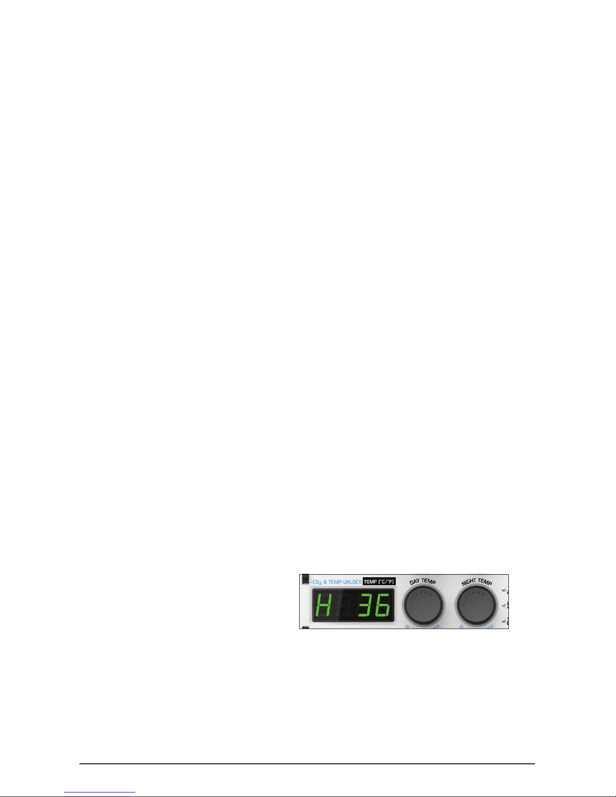
For daytime high limit temperature setting, click and hold the DAY TEMP knob for 3 seconds. The
display will flash “H (XX)” (Fig. 3) repeatedly. Turn the knob to change the setting. Click it again to
save the setting.
NOTE: To set night temps, the procedure is the same as described above for day temps, but the
NIGHT TEMP knob is used.
8
Page 9

DAYTIME MODE LED/ERROR LEDs/ERROR DISPLAY MESSAGES
The LED labeled DAYTIME MODE will illuminate when the controller is operating in daytime mode
(i.e., the photocell is receiving light).
S_SR: If this error message is being displayed, check the sensor’s connection to the controller.
OUTP: If the controller does not detect even a slight change in humidity
or temperature levels
within a 2-hour period, the screen will flash this error code accompanied by illumination of either
the COOLING ERROR, HEATING ERROR, or HUMIDITY ERROR LED. Press either of the corresponding
knobs (either of the TEMP or RH% knobs) to reset the error.
There are also four error LEDs on the bottom left of the controller. These lights will identify which
environmental factor the controller is reporting an error on.
SPECIFICATIONS
Max amperage 14.5 amps @ 120VAC 60 Hz
Power cord length 6.5'/2 m
Sensor cord length 15'/4.5 m
CO
2
Range 400-2000 PPM
CO
2
Accuracy +/- 100 PPM
Temp setting Adjustable 40-122°F (5-50°C)
Temp deadband (hysteresis) 2/4/6°F (1/2/3°C)
Temp accuracy ± 2°F/ ± 1°C
High temp limit adjustable 85-115°F (30-45°C)
Humidity setting range 5%-95% rH
Humidity accuracy ± 3% rH
Humidity deadband (hysteresis) 5% rH
Weight 3.5 lbs/1.6 kg
Dimensions 8.0" x 3.3" x 7.5"/202 x 85 x 191 mm
Indoor Use Only
9
Page 10
MOUNTING INSTRUCTIONS
MOUNTING THE UNIT TO A WALL
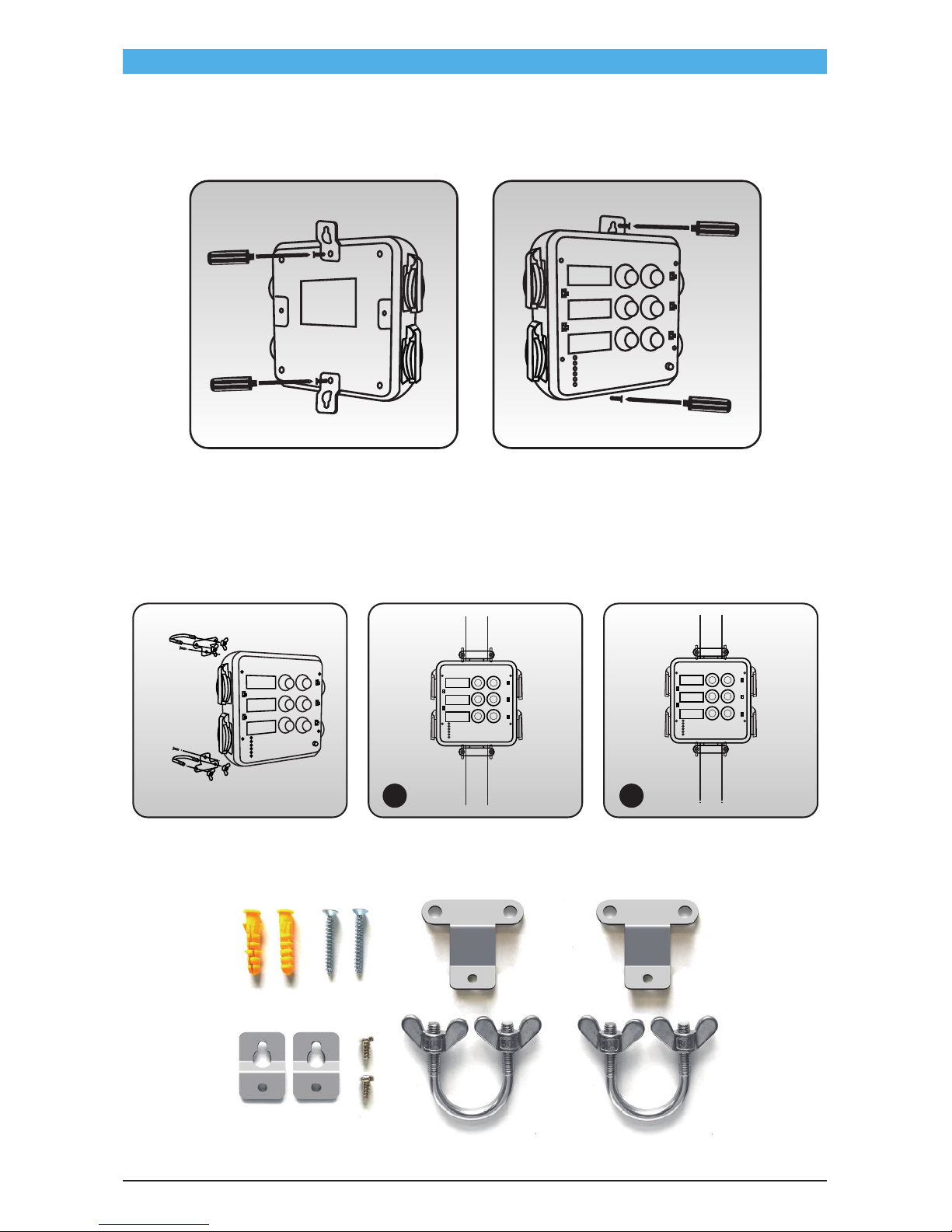
Secure the controller to the wall using the included mounting clips and screws.
MOUNTING THE UNIT TO A GROW TENT
Secure the controller to one of the grow tent’s vertical support rods with the included U-bolt
brackets.
1. Install on the inside of the grow tent.
2. Install on the outside of the grow tent (note that this method requires puncturing four holes
through the grow tent wall to allow the threaded ends of the U-bolts to emerge through the
grow tent’s fabric wall).
1 2
10
Page 11
GENERAL WARNINGS
1. Save the instructions. These safety and operating instructions must be kept in a safe place for
future reference.
2. All warnings on this product and in the instructions must be observed closely.
3. All operating instructions must be followed.
4. If the these instructions are not followed, damage to the product itself may result.
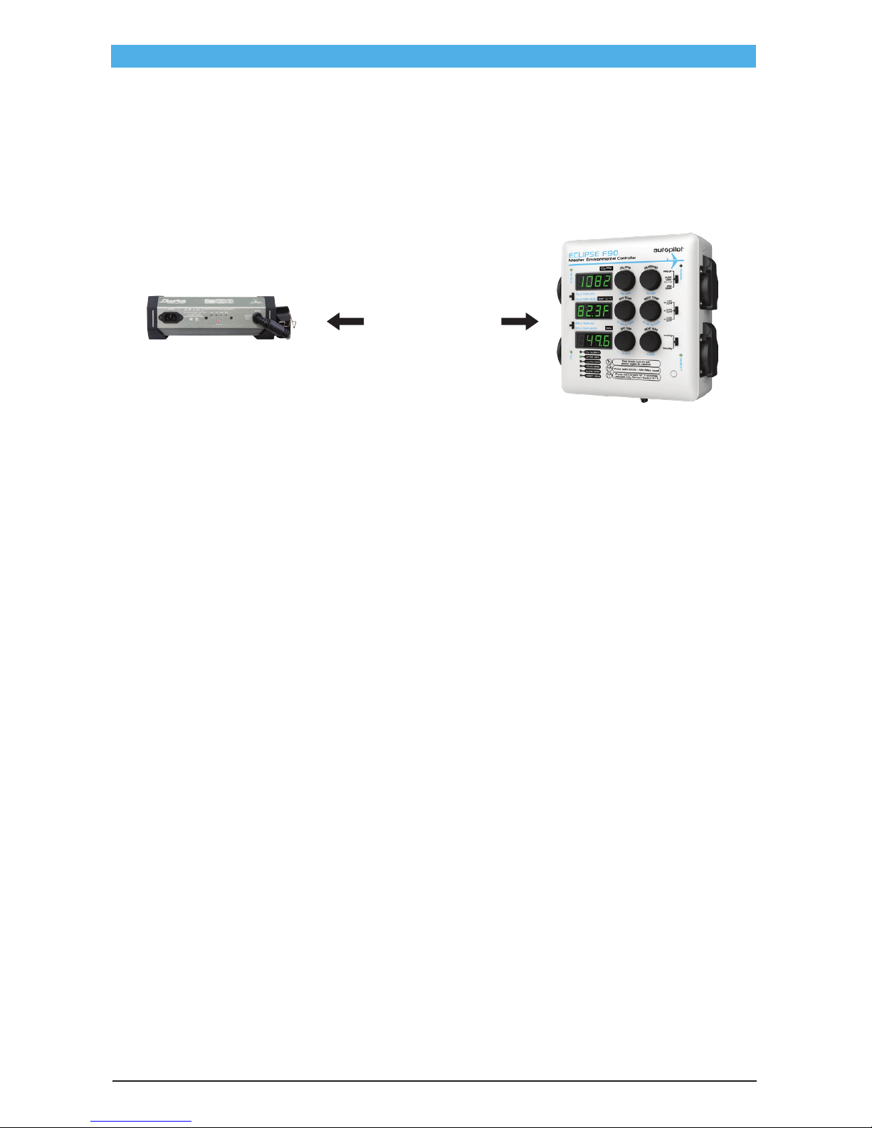
5. Install your controller at least 8' away from any devices that produce electronic interference,
such as electronic ballasts or ozone generators.
6. This controller can only accept standard 120V Nema 1-15P and Nema 5-15P plugs. Do not insert
any other plug type into it.
7. Do not use this controller near water or any water source. It should not be exposed to any
dripping or splashing water, as it is not waterproof nor shockproof.
8. Any serviceable parts inside or outside the unit should only be replaced by Hydrofarm.
9. If the power cord is damaged, please stop using the product immediately. Unplug the unit and
contact the retailer you purchased it from.
10. The unit is equipped with a circuit breaker that will automatically shut it down at once. All
outlets of the product all have the safety ground.
11. Do not install the unit near any heat source.
12. Do not block any ventilation openings in the controller housing.
13. This product is a Safety Class I Controller and is equipped with a Nema 5-15P plug. The main
plug should only be inserted into a properly grounded power outlet. Any alteration of the
power cord is likely to make the product dangerous and will void the warranty.
SULFUR VAPORIZER WARNING
If a sulfur vaporizer is used, first remove the remote sensor unit from the affected area or turn
the controller off and cover the remote sensor probe with a protective plastic bag. Remove
the bag before turning the power back on. Failure to protect the sensor while using a sulfur
vaporizer will result in damage to its infrared component and will void the warranty.
8' (2.5 m)
minimum
11
Page 12

Hydrofarm.com
APE4200 Instructions revised - January 8, 2018 11:21 AM
LIMITED WARRANTY
Hydrofarm warrants the APE4200 to be free from defects in materials and workmanship. The warranty term is for
2 years beginning on the date of purchase. Misuse, abuse, or failure to follow instructions is not covered under this
warranty. Hydrofarm’s warranty liability extends only to the replacement cost of the product. Hydrofarm will not be
liable for any consequential, indirect, or incidental damages of any kind, including lost revenues, lost profits, or other
losses in connection with the product. Some states do not allow limitation on how long an implied warranty lasts or
the exclusion of incidental or consequential damages, so the above limitations or exclusions may not apply to you.
Hydrofarm will, at our discretion, repair or replace the APE4200 covered under this warranty if it is returned to the
original place of purchase. To request warranty service, please return the APE4200, with original sales receipt and
original packaging, to your place of purchase. The purchase date is based on your original sales receipt.
WARRANTY
Like us on Facebook, follow us on Twitter,
and check out Hydrofarmtv on YouTube and Instagram!
Get Connected with the Hydrofarm Community:
precise climate control
precise climate control
Thank you for choosing Autopilot by Hydrofarm. For further information about Autopilot
products, videos, and technical information,
please visit AutopilotControllers.com
ADDITIONAL LANGUAGES OF THESE INSTRUCTIONS CAN BE FOUND AT Hydrofarm.com
 Loading...