


Modula Documentation
ESD Warning
q
Safety Information & Notices
q
Welcome
q
Installation and Setup Guide
q
Warranty/Service & Returns
q
Glossary
q
Control Options
CP-20A Control Panel Operation (Front)
q
CP-10 Control Panel Operation (Front & Remote)
q
CP-20 Control Panel Operation (Front & Remote)
q
q
Serial Control Operation (BCS)
Enclosure (Board Set) Supplements*
q
Standard Video Enclosures
q
S-Video & Stereo Enclosures
q
CAT-5 Video & Audio Enclosures
q
CAT-5/RGBHV Enclosure
q
Wideband Enclosures
q
Stereo (with Wideband) Enclosures
q
SDI Digital Video Enclosures
q
Series4 (CatPro and RGBHV/HD-15) Enclosures
q
RS-422 Enclosures
Mounting Accessories
q
Transmitter/Receiver Module Mounting Plate
q
Module Rack Mounting Tray
q
12-Box Rack Mount 4 RU Enclosure
Miscellaneous Supplements
q
CAT-5 Wiring Diagrams for Transmitter/Receiver Link Cable
* To search the Enclosure Supplements according to board signal type, see the
chart on the next page.
August 2007
Modula Documentation
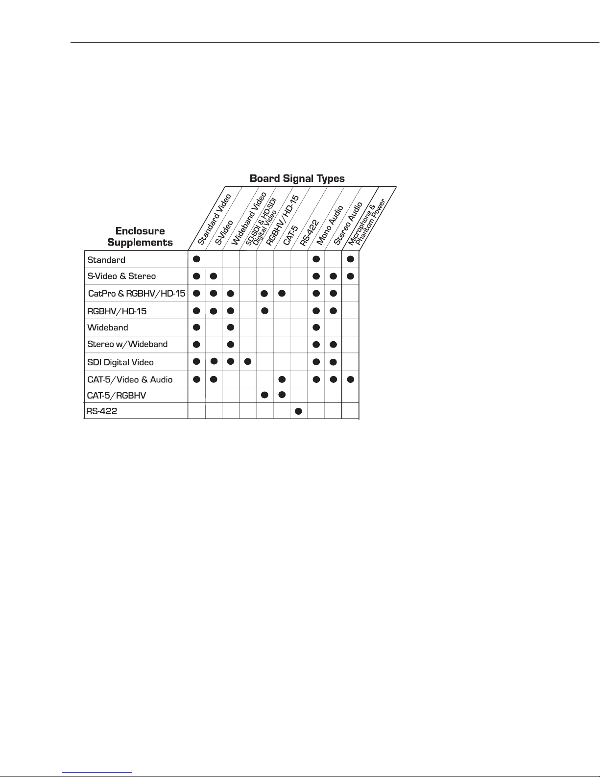
Board Signal Types
Each Enclosure (Board Set) Supplement includes a chapter for each board signal
type that can be used in that enclosure. The dots in the chart below indicate
which Enclosure Supplements contain information for the different signal types.
Click the Enclosure Supplement name on the left to go to that supplement.
August 2007

ESD Warning
To avoid ESD (Electrostatic Discharge) damage to sensitive components,
make sure you are properly grounded before touching any internal
materials.
When working with any equipment manufactured with electronic
devices, proper ESD grounding procedures must be followed to ensure
people, products, and tools are as free of static charges as possible.
Grounding straps, conductive smocks, and conductive work mats are
specifically designed for this purpose.
Anyone performing field maintenance on AutoPatch equipment should
use an appropriate ESD field service kit complete with at least a
dissipative work mat with a ground cord and a UL listed adjustable wrist
strap with another ground cord. These items should not be manufactured
locally, since they are generally composed of highly resistive conductive
materials to safely drain static charges, without increasing an
electrocution risk in the event of an accident. ESD protective equipment
can be obtained from 3M
Systems
®
, and other such vendors.
™
, Desco®, Richmond Technology®, Plastic
Modula Binder Introduction

Important Safety Information
and Instructions
When using and installing your AutoPatch product, adhere to the following basic safety
precautions. For more information about operating, installing, or servicing your
AutoPatch product see your product documentation.
Read and understand all instructions before using and installing AutoPatch products.
ä
Use the correct voltage range for your AutoPatch product.
ä
There are no user serviceable parts inside an AutoPatch product; service should only
ä
be done by qualified personnel.
If you see smoke or smell a strange odor coming from your AutoPatch product, turn
ä
it off immediately and call AutoAssist.
Turn off and unplug an enclosure before adding or removing boards, unless otherwise
ä
specified in that product’s documentation.
To avoid shock or potential ESD (Electrostatic Discharge) damage to equipment,
ä
make sure you are properly grounded before touching components inside an
AutoPatch product.
For products with multiple power supplies in each unit, make sure all power supplies
ä
are turned on simultaneously.
ä
Use surge protectors and/or AC line conditioners when powering AutoPatch
products.
ä
Only use a fuse(s) with the correct fuse rating in your enclosure.
ä
Make sure the power outlet is close to the product and easily accessible.
ä
Make sure the product is on or attached to a stable surface.
ä
Turn off equipment before linking pieces together, unless otherwise specified in that
product’s documentation.
ä
For safety and signal integrity, use a grounded external power source and a grounded
power connector.
Safety
Modula Binder Introduction

Safety
Information et directives
de sécurité importantes
Veuillez vous conformer aux directives de sécurité ci-dessous lorsque vous installez et
utilisez votre appareil AutoPatch. Pour de plus amples renseignements au sujet de
l’installation, du fonctionnement ou de la réparation de votre appareil AutoPatch, veuillez
consulter la documentation accompagnant l’appareil.
Lisez attentivement toutes les directives avant d’installer et d’utiliser les appareils
ä
AutoPatch.
Le voltage doit être approprié à l’appareil AutoPatch.
ä
Les appareils AutoPatch ne contiennent aucune pièce réparable par l’usager; la
ä
réparation ne doit être effectuée que par du personnel qualifié.
Si de la fumée ou une odeur étrange se dégagent d’un appareil AutoPatch, fermez-le
ä
immédiatement et appelez le Service de soutien technique (AutoAssist).
Fermez et débranchez le boîtier avant d’ajouter ou d’enlever des plaquettes, à moins
ä
d’indication contraire fournie dans la documentation du appareil.
Pour éviter les chocs ou les dommages éventuels causés à l’équipement par une
ä
décharge électrostatique, veillez à ce le dispositif oit bien relié à la terre avant de
toucher les composantes se trouvant à l’intérieur d’un appareil AutoPatch.
ä
Veillez à ce que tous les blocs d’alimentation des appareils dotés de blocs
d’alimentation multiples dans chaque unité soient allumés simultanément.
ä
Servez-vous de protecteurs de surtension ou de conditionneurs de lignes à courant
alternatif lorsque vous mettez les appareils AutoPatch sous tension.
ä
Placez uniquement des fusibles de calibre exact dans les boîtiers.
ä
Veillez à ce que la prise de courant soit proche de l’appareil et facile d’accès.
ä
Veillez à ce que votre appareil AutoPatch soit installé sur une surface stable ou qu’il
y soit fermement maintenu.
ä
Fermez toutes les composantes de l’équipement avant de relier des pièces, à moins
d’indication contraire fournie dans la documentation de l’appareil.
ä
Par mesure de sécurité et pour la qualité des signaux, servez-vous d’une source
d’alimentation externe mise à la terre et d’un connect d’alimentation mis à la terre.
Modula Binder Introduction

Notices
AutoPatch©2003, all rights reserved. No part of this publication may be reproduced,
stored in a retrieval system, or transmitted, in any form or by any means, electronic,
mechanical, photocopying, recording, or otherwise, without the prior written permission
of AutoPatch. Copyright protection claimed extends to AutoPatch hardware and software
and includes all forms and matters copyrightable material and information now allowed
by statutory or judicial law or here in after granted, including without limitation, material
generated from the software programs which are displayed on the screen such as icons,
screen display looks, etc. Reproduction or disassembly of embodied computer programs
or algorithms is expressly prohibited.
No patent liability is assumed with respect to the use of information contained herein.
While every precaution has been taken in the preparation of this publication, AutoPatch
assumes no responsibility for error or omissions. No liability is assumed for damages
resulting from the use of the information contained herein.
Further, this publication and features described herein are subject to change without
notice. The United States Federal Communications Commission (in 47CFR 15.838) has
specified that the following notice be brought to the attention of the users of this product.
Federal Communication Commission Radio Frequency Interference Statement:
“This equipment has been tested and found to comply with the limits for a Class A digital
device, pursuant to Part 15 of the FCC Rules. These limits are designed to provide
reasonable protection against harmful interference when the equipment is operated in a
commercial environment. This equipment generates, uses, and can radiate radio
frequency energy and, if not installed and used in accordance with the instruction
manual, may cause harmful interference to radio communications. Operation of this
equipment in a residential area is likely to cause harmful interference in which case the
user will be required to correct the interference at his own expense.
Notices
If necessary, the user should consult the dealer or an experienced radio/television
technician for additional suggestions. The user may find the booklet, How to Identify
and Resolve Radio-TV Interference Problems, prepared by the Federal Communications
Commission to be helpful.”
Modula Binder Introduction

This booklet is available from the U.S. Government Printing Office, Washington, D.C.
20402, Stock N. 004-000-00345-4.
Use shielded cables. To comply with FCC Class B requirement, all external data interface
cables and adapters must be shielded.
®
AutoPatch
N
Net™, and XNConnect®are trademarks of XNTechnologies, Inc.
X
MS-DOS
, AutoAssist®, Modula®, Flex-Slot™, Ultra-Flat Response Certified™,
®
, Windows®, and Windows95®are registered trademarks of Microsoft
Corporation.
®
, Desco®, Richmond Technology®, and Plastic Systems®are registered trademarks.
3M
®
Neuron
and LonTalk®are registered trademarks of Echelon.
Notices
TosLink
Ethernet
®
is a registered trademark of the Toshiba Corporation.
®
is a registered trademark of the Xerox Corporation.
Modula Binder Introduction

Welcome
Welcome to the Modula Documentation & Software Binder. The first
four sections of this binder each have their own Contents and, with the
exception of short Boards & Specifications sections, their own Index.
This binder has been assembled with information for the Modula
Distribution Matrix that you ordered. It includes directions for operating
the particular type of control panel you selected and for attaching sources
and destination to the specific boards installed for your custom
configuration. This binder is organized into the following tabbed
sections:
Installation & Setup – Designed to provide the installation technician
with quick, easy-to-follow instructions for installing a Modula
Distribution Matrix and preparing it for operation.
Boards & Specifications – Contains information on individual types of
boards and their specifications.
Front Panel Operation – Designed for the end-user operating a system
with a local front panel.
Welcome
Serial Control Operation (BCS) – Designed for the end-user operating
a system by serial control using BCS (Basic Control Structure) protocol
information.
Warranty / Service & Returns – Includes warranty and service
information.
Glossary – Contains an alphabetical listing of terms and definitions
common to AutoPatch products.
Modula Binder Introduction i

Welcome
Welcome
The Modula Documentation & Software Binder also contains the
following material:
Quick Reference Guide (for operation) – included with the Front
Panel Operation section.
AutoPatch Software and Documentation CD ROM – in the right front
pocket.
AutoPatch Modula Connector Guide – in the back pocket.
The AutoPatch Software and Documentation CD includes an interface
N
library, the X
Net Communication Library, with programming examples
for programmers who want to set up their own control programs.
The Modula Documentation & Software Binder does not include any
detailed information about SBCs (Single Bus Controllers), remote
control panels, or status display devices for the Modula. Visit our web
site, www.autopatch.com, or call AutoAssist for more information about
these accessories (see Technical Support, page iii).
Product Notes
A Modula Distribution Matrix can stand alone or comprise a virtually
unlimited number of linked enclosures, including any other AutoPatch
products with an X
enclosure can hold up to 16 boards with 4 connectors each. The
Modula’s Flex-Slot
combinations of input to output connectors: 32x32, 4x60, 8x56, 12x52,
16x48, 60x4, 56x8, 52x12, and 48x16, as well as subsets of these
configurations (for example, 12x4 or 8x36). In addition, boards in a
Modula Series4™ Distribution Matrix (a compact 4 RU) route up to
32x32 RGBHV signals through DB-15 connectors.
Note: Please note the Modula Distribution Matrix is available in
several models and various configurations, so the illustrations in this
binder may differ from the model(s) you purchased.
Modula Distribution Matrices fit in a broad range of audio/video/data
environments and are controllable from a variety of sources, including
local control panels, remote control panels, or any control device that can
send ASCII characters through an RS232 or RS422 serial cable.
N
Net network compatible interface. Each Modula
™
frame provides enclosure capacity for nine
ii Modula Binder Introduction

Technical Support
Modula features include:
Ability to mix a variety of audio, video, and data boards in a single
q
enclosure
Modular in increments of 4 inputs and 4 outputs per signal type
q
High bandwidth-linearity and low crosstalk
q
Controllable via Ethernet, Neuron®, RS-232/RS-422,
q
local control panels, remote control panels, and Single Bus
Controllers, plus links to status display devices
Optional redundant power supplies and vertical-interval switching
q
Programmable macro functions
q
Supports paralleled multi-channel signal routing
q
System self-diagnostics
q
Ultra-Flat Response Certified
q
Lifetime Warranty (see Warranty tab at the back of this binder)
q
™
Technical Support
AutoPatch provides technical support 24 hours a day, 7 days a week
(except for U.S. holidays). Before calling with a question, please consult
the Modula documentation. If this binder cannot fully answer your
question, have your serial number ready (located on the expansion plate
to the right of the power receptacle on the rear of the enclosure) and call
your authorized AutoPatch dealer or call AutoPatch AutoAssist at: (toll
free for U.S. and Canada) 800-622-0246 or (international) 509-235-2636.
You can also reach us through our web site: www.autopatch.com,or
e-mail our AutoPatch Technical Support Specialists at:
support@autopatch.com
Welcome
Modula Binder Introduction iii

Welcome
Icon Legend
ESD Warning: The icon to the left indicates text regarding potential
danger associated with the discharge of static electricity from an outside
source, such as human hands, into an integrated circuit, often resulting
in damage to the circuit.
Caution: The icon to the left indicates text that cautions readers against
actions that could cause potential injury to the product or the possibility
of serious inconvenience.
Start of Procedure: The icon to the left indicates the start of a
procedure. Procedures are usually numbered, unless only one step.
Welcome
iv Modula Binder Introduction


Contents
Chapter 1 – Unpacking the Modula
Front of the Enclosure ........................................1-2
Rear of the Enclosure ........................................1-3
Chapter 2 – Placing the Enclosure(s)
Site Recommendations .......................................2-2
General Hazard Precautions ..............................2-2
Installation Procedure ........................................2-3
Chapter 3 – Linking Enclosures
Chapter 4 – Attaching Inputs and Outputs
Chapter 5 – Attaching an External Controller
Connecting a Serial Controller .................................5-2
Serial Communication Settings ................................5-3
Chapter 6 – Applying Power and the Startup Sequence
Applying Power ..............................................6-2
CP-20 Control Panel Startup ..................................6-2
CP-10 Control Panel Startup ..................................6-3
Serial Control Device Startup..................................6-3
Chapter 7 – Executing a Test Switch
Executing a Test Switch Using the CP-20 Control Panel ..........7-2
Executing a Test Switch Using the CP-10 Control Panel ..........7-4
Executing a Test Switch Using BCS Commands .................7-6
Technical Support ............................................7-6
Modula Installation & Setup

Contents
Chapter 8 – Managing Configuration Files
Conceptual Overview .........................................8-2
Installing and Launching XNConnect ...........................8-2
User Interface ...............................................8-4
Opening and Downloading a Configuration File...................8-5
Modifying a Configuration File..................................8-5
Modifying Source and Destination Labels ...................8-6
Configuring Local Presets.................................8-6
Modifying Groupings......................................8-9
Grouping Pattern Examples ..................................8-14
Spanning Grouping Pattern Example ......................8-14
Sequential Grouping Pattern Example .....................8-15
Chapter 9 – Paralleling Inputs
Paralleling Inputs.............................................9-2
Controlling Paralleled Inputs...................................9-3
CP-20 Operation of Paralleled Inputs .......................9-3
CP-10 Operation of Paralleled Inputs ......................9-3
BCS Operation of Paralleled Inputs.........................9-3
Chapter 10 – Adding Boards
Input and Output Boards ....................................10-2
Vertical Interval Sync Board..................................10-4
Termination Load Jumper ...............................10-4
External Connections....................................10-5
Installing a VI Sync Board ................................10-5
Verifying System Recognition of the VI Sync Board .........10-7
Enabling the VI Sync Board ..............................10-7
Index
Modula Installation & Setup

Unpacking the Modula
The Modula is shipped with one enclosure in each shipping box. Order
invoices are sent separately. Each box contains one of each of the
following items:
Enclosure
q
Power cord
q
The shipping boxes are marked as “Box #_ of _,” where the first blank is
the box number and the second blank is the total number of boxes in the
shipment. Box #1 contains several additional items:
Unpacking
q
Packing list
q
AutoPatch Modula Documentation & Software Binder
q
Quick Reference Guide (included with Front Panel Operation
section)
q
Modula Connector Guide (inside binder)
q
AutoPatch Software and Documentation CD ROM (inside binder)
q
Link cable and T-connectors (included with multi-enclosure
systems)
q
50 ohm termination connector(s)
q
Other enclosure products
Modula Installation & Setup 1-1

Unpacking the Modula
Unpacking Tips
Before fully unpacking the enclosure(s), examine the shipping
q
box(es) for any signs of damage. If a box is partially crushed or any
Unpacking
sides have been broken open, notify the shipping agency
immediately and contact your AutoPatch Salesperson or
Representative (see the Warranty/Service & Returns section of this
binder).
Once unpacking is complete, closely check the physical condition of
q
the enclosure(s).
Collect all documentation and envelopes.
q
Note: AutoPatch is not responsible for damage caused by insufficient
packing during return shipment to the factory. Upon request, AutoPatch
will supply new shipping boxes at cost.
1.1 Front of the Enclosure
Enclosures are the structural basis of a Modula Distribution Matrix.
Since AutoPatch matrix switchers are custom-built for each installation,
factors such as control method and signal types affect the appearance and
weight of each enclosure.
An enclosure may have either a blank front panel or one of various
control panels (local front or remote panels produced by AutoPatch for
controlling the system’s switches and system attributes). Although
control panels are optional, we recommend one per system for system
verification, redundant control, and troubleshooting. Local control panels
can be removed or attached as needed; note, however, that the
enclosure’s power must be off during removal and installation of a front
panel. Illustrations and directions for control panel use are provided in
the Front Panel Operation section of this binder.
1-2 Modula Installation & Setup

Rear of the Enclosure
1.2 Rear of the Enclosure
Enclosures, as viewed from the rear, will vary depending on the
configuration. From left to right you will generally find the following:
Power receptacle
ä
Expansion/control slot with serial number
ä
Input and output boards, sometimes with empty board slots
ä
(up to a combined total of sixteen)
Expansion/control slot (may contain a Vertical Interval Sync board
ä
in video enclosures)
Expansion/control slot with CPU board
ä
Power Receptacle
Expansion/Control Slots
CPU Board in
Expansion/Control Slot
Unpacking
Serial Number
Figure 1: Rear view of a Modula enclosure
Figure 2: Rear view of a Modula Series4 enclosure
Input Connectors
The following segments briefly introduce the hardware on the rear of the
enclosure.
Output Connectors
Modula Installation & Setup 1-3

Unpacking
Unpacking the Modula
Input and Output Connectors
OUT
1
2
3
4
OUT
10
6
OUT
11
7
12
8
OUT
18
14
OUT
19
15
0
2
16
OUT
26
22
OUT
27
23
28
24
+
+
1
2
IN
3
4
10
6
IN
IN
11
7
12
8
18
14
IN
IN
19
15
20
16
26
22
IN
IN
27
23
28
24
+48V
OFF
+48V
FF
O
+48V
FF
O
V
48
+
OFF
+
+
25
21
17
13
9
5
25
21
17
13
9
5
Figure 3: Numbering starts with top channel of left-most board
Input and output connectors are the attachment points for devices that
connect to the system. The number and type of connectors depend on the
number and type of input and output boards. Input and output connectors
are numbered separately. Depending on the configuration, different types
of boards may also be numbered separately. The four connector numbers
for each board are above and to the right of its top connector. This
numbering pattern continues on each board (see Figure 3).
Looking at the rear of the enclosure, the inputs (sources) are on the left
side, and the outputs (destinations) are on the right side. BNC connectors
are also color coded; the white connectors are inputs and the black
connectors are outputs.
A single enclosure can handle a combination of signals, such as analog
audio, analog video, digital video, sync, etc. See the Boards &
Specifications section of this binder for information on the individual
types of boards, their connectors, and specifications that are available for
your model.
Expansion/Control Slots
Each enclosure provides three expansion/control slots (see Figure 1).
The one farthest to the right contains the CPU. The one to the right of the
power receptacle and the one to the left of the CPU board are for future
boards to increase functionality and add new features to your system.
1-4 Modula Installation & Setup
Rear of the Enclosure
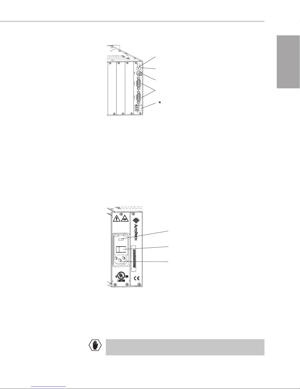
CPU
System Status Indicator
Communication Status Indicator
Ethernet Port
Serial Ports
X Net Communication Link Port (with connector)
Figure 4: CPU Board
The CPU is in the farthest right expansion/control slot and has an
Ethernet port (recommended for linking enclosures) and two serial port
connectors (for attaching external control devices). Two indicators are at
the top of board, one for system status and the other for indicating
communication activity. In addition, the X
N
Net Communication Link
port at the bottom of the board is for linking to AutoPatch control
devices (such as SBCs), remote control panels, and display units.
Unpacking
Power Receptacle
2A 250V
CAUTION - For
continued protection
against risk of fire,
replace only with same
type and rating of fuse.
Cheney, WA USA, 509-235-2636
A Div. of XN Technologies, Inc.
01051901001PREC030001
Fuse
Power Switch
Power Receptacle
100-240VAC
50/60Hz 2A Max.
UL 60950
E177015
Figure 5: Power Receptacle
The power receptacle is in the farthest left slot on the rear of the
enclosure. This unit contains a fuse, a power switch, and the power
receptacle. Press the “0” side of the power switch to turn it off; press the
“1” side to turn it on.
Caution: Double Pole/Neutral Fusing–fuses are used both in the “live”
phase and “neutral” phase of the device.
Modula Installation & Setup 1-5

Modula Redundant Power Supplies
This page replaces the information on page 1-6 of the
Installation & Setup section of the Modula Documentation &
Software binder. Please insert this page after page 1-6.
Modula Redundant Power Supplies
RPS Indicator
Figure 6: RPS (Redundant Power Supply) Indicator
Modula Distribution Matrices can be ordered with a Redundant Power
Supply (RPS). All Modula enclosures are equipped with an RPS
Indicator on the front of the enclosure (see Figure 6).
The RPS LED indicates the presence and functionality of the power
supplies:
ä
Not Illuminated – The system does not have an RPS.
ä
Green – Both power supplies are working.
ä
Red – One of the power supplies has failed; contact AutoAssist.
Caution: If the RPS fails, it should be replaced as soon as possible to
avoid damaging the remaining power supply. Contact AutoAssist for
replacement information (see Technical Support below).
Technical Support
AutoPatch provides technical support 24 hours a day, 7 days a week
(except for U.S. holidays). Have your serial number ready. The number
is normally located on the rear of the enclosure.
March 2006 Modula Installation & Setup (Replacement) 1-6
AutoAssist Contact Information
ä
Toll-free U.S. and Canada – 800-622-0246
ä
International – 509-235-2636
ä
Website – www.autopatch.com
ä
Email – support@autopatch.com

Unpacking
Unpacking the Modula
Redundant Power Supplies
RPS Indicator
Figure 6: RPS (Redundant Power Supply) Indicator
Modula CAT-5 Series Distribution Matrices are the only Modula
enclosures equipped with Redundant Power Supplies (RPS) and an RPS
Indicator.
Caution: If a power supply fails, the RPS indicator on the front
illuminates. A failed power supply should be replaced as soon as
possible to avoid damaging the remaining power supply. Call
AutoAssist for replacement information (see Technical Support,
page 7-6).
1-6 Modula Installation & Setup

Placing the Enclosure(s)
This chapter covers site recommendations and provides a step-by-step
procedure for installing a Modula Distribution Matrix in a rack.
General specifications that may be useful before installation include:
Approvals CE, UL, cUL
Placing Enclosures
AC Power
Frequency 47 - 63 Hz
Humidity 0 to 90% non-condensing
Dimensions 3 RU
Dimensions 4 RU
Weight
Fuse 2 Amp time lag (5 mm x 20 mm)
100 - 240 VAC single phase (47-63 Hz)
240 Watt maximum per enclosure
17 in. (43.18 cm) depth
18.77 in. (47.68 cm) width with mounting ears
17.4 in. (44.20 cm) width without mounting ears
5.25 in. (13.34 cm) height
17 in. (43.18 cm) depth
18.77 in. (47.68 cm) width with mounting ears
17.4 in. (44.20 cm) width without mounting ears
7.0 in. (17.78 cm) height
Approximately 22-24 lb. (9.98 -10.88 kg) per
enclosure
For individual board information and specifications, see the Boards &
Specifications section of this binder. Full specifications for all AutoPatch
products are located on the AutoPatch web site (www.autopatch.com).
Modula Installation & Setup 2-1

Placing Enclosures
Placing the Enclosure(s)
2.1 Site Recommendations
When placing the enclosure, site recommendations should be considered
to reduce potential hazards in regard to environment, power, chassis
accessibility, and cooling and airflow.
To make control panel operations easier, mount the enclosure with the
control panel attached in the rack at eye level. The optimum viewing
angle for the LCD screen is 15°.
General Hazard Precautions
The recommendations listed address potential hazards that are considered
common to most rack installations:
Elevated Operating Ambient Temperature
Consideration should be given to installing the equipment in an
environment compatible with the manufacturer’s maximum rated
ambient temperature. This precaution is advised because in a closed or
multi-unit rack assembly, the operating ambient temperature of the rack
environment may be greater than the ambient room temperature.
Caution: To protect the equipment from overheating, do not operate in
an area that exceeds the maximum recommended ambient temperature
of 104° F (40° C). To prevent airflow restriction, allow at least 3 inches
(7.6 cm) of clearance around the enclosure openings for proper airflow.
Reduced Air Flow
Installation of the equipment in a rack should be such that the amount of
air flow required for safe operation of the equipment is not compromised.
Caution: Avoid placing high heat-producing equipment directly above
or below the enclosure(s). Modula enclosures are designed to adequately
dissipate the small amount of heat they produce under normal operating
conditions; however, this design is defeated when high heat-producing
equipment is placed directly above or below the enclosure(s).
Mechanical Loading
Mounting of the equipment in the rack should be such that a hazardous
condition is not created due to uneven mechanical loading.
2-2 Modula Installation & Setup

Installation Procedure
Circuit Overloading
Consideration should be given to the connection of the equipment to the
supply circuit and the effect that overloading of circuits might have on
over current protection and supply wiring.
Reliable Earthing (Grounding)
Reliable earthing of rack-mounted equipment should be maintained.
Particular attention should be given to supply connections other than
direct connections to the branch circuit (e.g., use of power strips).
Caution: To avoid system damage, turn on all power switches in a
system at the same time. WE RECOMMEND ATTACHING ALL
POWER CORDS TO A SINGLE SURGE PROTECTOR AND/OR AN
AC LINE CONDITIONER.
2.2 Installation Procedure
The Modula Distribution Matrix enclosure can be mounted in a standard
EIA 19 in. (48.26 cm) rack. To hold the enclosure(s) in place, rack
installation ears are included. Directions for mounting rack ears are
included in the rack installation instructions on page 2-4.
Items needed for rack installation:
q
Enclosure(s)
q
Power cord
Placing Enclosures
q
Rack ears
q
Screwdriver
q
Screws that fit your rack [for mounting the enclosure(s)]
q
Link cables and T-connectors (included with multi-enclosure
systems, otherwise not needed)
q
50 ohm termination connector(s)
q
Standard EIA 19 in. (48.26 cm) rack
Optional:
q
A laptop computer with an RS232 null modem cable
(for communication with the Modula via a serial port)
q
Surge protector(s) – highly recommended
Modula Installation & Setup 2-3

Placing Enclosures
Placing the Enclosure(s)
To install an enclosure in a rack:
1. On the side of the enclosure, remove the two screws closest to the
front panel.
2. Align the holes on one of the rack ears with the empty holes on the
side of the enclosure; insert the two screws from step 1 and the two
screws included with the rack ears and tighten (see Figure 7).
Figure 7: Attach rack ears to the ends of the enclosure
3. Repeat steps 1 and 2 for the other rack ear.
4. Place the enclosure in the rack and attach front-mounting screws to
hold it firmly in place (repeat for each enclosure).
Tip: You may find it easiest to install the top enclosure first and
move down from there.
Figure 8: Place in rack and fasten with mounting screws
2-4 Modula Installation & Setup

Installation Procedure
5. If the system contains only one enclosure, add a 50 ohm terminating
connector to the Ethernet port.
If the system contains multiple enclosures, link them (see Chapter 3,
“Linking Enclosures”) and add 50 ohm termination connectors to the
exposed ends of the T-connectors on the first and last enclosures.
6. Following the “Modula Connector Guide” (inside the back cover of
this binder), attach only the first two input and output signals to the
correct input and output connectors on the rear of each enclosure (see
the Boards & Specifications section of this binder for specific board
connector information and specifications).
7. Attach power to each enclosure and turn on the entire system (see
Chapter 6, “Applying Power and the Startup Sequence”).
WE RECOMMEND USING SURGE PROTECTORS AND/OR AN
AC LINE CONDITIONER.
Placing Enclosures
8. Perform a test switch to ensure the system is working properly (see
Chapter 7, “Executing a Test Switch”).
9. When the test switch works correctly, attach all the input and output
cables to the correct input and output connectors on the rear of each
enclosure (refer to the “Modula Connector Guide.”)
Modula Installation & Setup 2-5

Linking Enclosures
A Modula enclosure can connect to other AutoPatch enclosures with
Ethernet compatible interfaces.
Link Port Cable Type Space between Enclosures (max)
Ethernet (these cables
are included with
multi-enclosure systems)
RG-58 500 ft. (150 m)
Linking enclosures in a multi-enclosure system allows control
information to pass between them with the Ethernet ports providing
consistent control speed. In a multi-enclosure system with an external
controller, the enclosure connected to the control device receives all
control information and passes on relevant information to other
enclosures via the links. A Modula can have a virtually unlimited number
of linked enclosures.
Note: If any of the linked enclosures were not part of the original
system, a new configuration file is included on the AutoPatch CD ROM
shipped with the new enclosures. Follow the instructions for installing
N
X
Connect on page 8-2 and for downloading the new configuration file
on page 8-5.
You can link Modula enclosures in any configuration (except a closed
circle) using link cables and the Ethernet connectors on the CPU (see the
linking illustrations on the following pages).
Linking Enclosures
Caution: Enclosures must be cabled correctly after linking. Check the
“Modula Connector Guide” and the ENC (enclosure) number on the
plate to the right of the power receptacle to ensure you are attaching the
correct signal cables to the correct enclosure (see Figures 9 and 10).
Modula Installation & Setup 3-1

Linking Enclosures
To link two Modula enclosures using Ethernet link connectors:
1. Fasten T-connectors to the Ethernet ports on both enclosures.
2. Fasten the connectors on the ends of the Ethernet link cable onto the
T-connectors.
3. Add 50 ohm termination connectors as shown in Figure 9.
Note: 50 ohm termination connectors are required on the open ends of
all T-connectors when linking enclosures.
50 Ohm Termination Connectors
ENC1
Enclosure Numbers
Linking Enclosures
ENC2
Figure 9: Link enclosures via their Ethernet link ports
3-2 Modula Installation & Setup

To link more than two enclosures via the Ethernet connector:
1. Fasten T-connectors to the Ethernet ports on all the enclosures.
2. Fasten a connector on the first Ethernet link cable onto the
T-connector on the first enclosure.
3. Fasten the connector on the other end of the first Ethernet link cable
onto the T-connector on the second enclosure, repeating as necessary
for additional enclosures.
4. Add 50 ohm termination connectors on the open ends of the
T-connectors on the first and last enclosure as shown in Figure 10.
Note: 50 ohm termination connectors are required on the open ends of
all T-connectors when linking enclosures.
ENC1
Linking Enclosures
Enclosure Numbers
50 Ohm
Termination Connectors
ENC2
ENC3
Figure 10: Link more than two enclosures via the Ethernet link port
Modula Installation & Setup 3-3
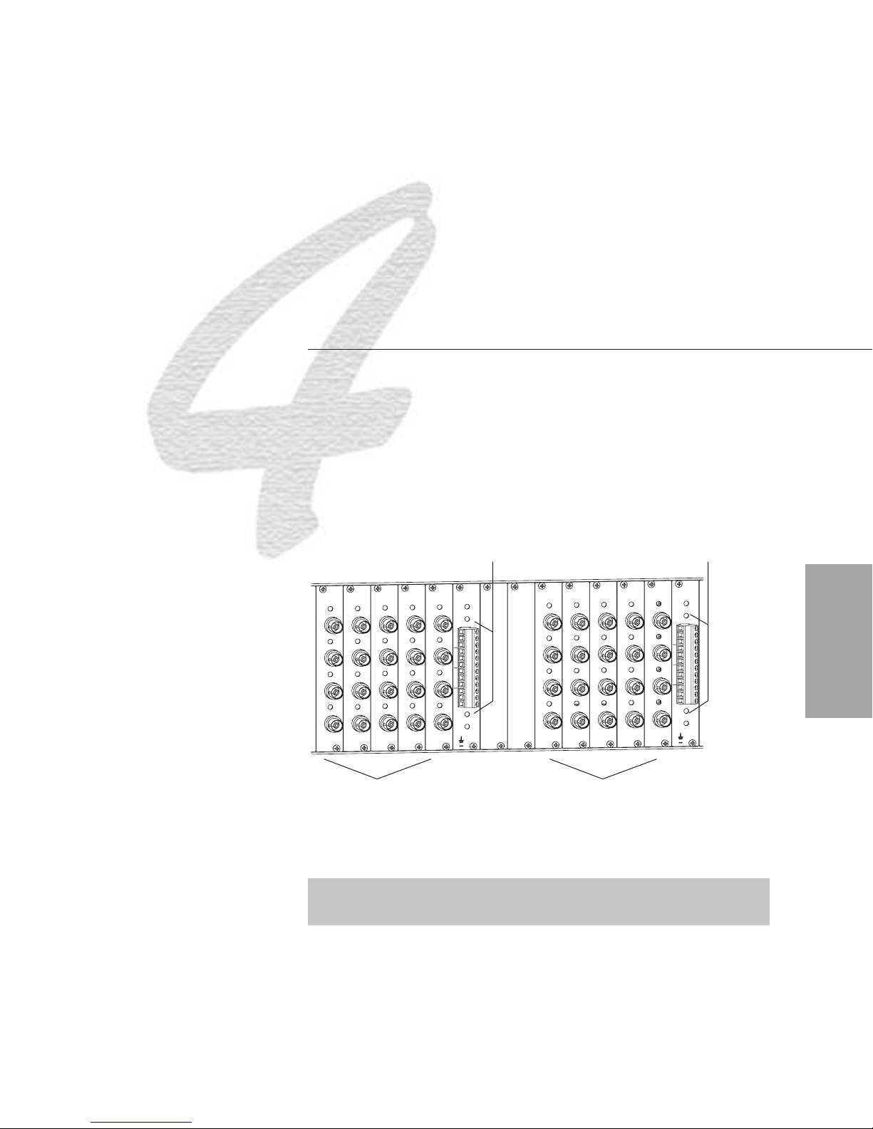
Attaching
Inputs and Outputs
Inputs (sources) and outputs (destinations) attach to the input and output
connectors on the rear of each enclosure. Inputs attach to the connectors
on the left side of the enclosure, and outputs attach to the connectors on
the right side. The input and output connectors are numbered separately.
The four connector numbers for each board are above and to the right of
its top connector. This numbering pattern continues on each board (see
Figure 11).
Audio inputs
Audio outputs
1
6
2
IN
IN
7
3
8
4
14
10
IN
IN
15
11
16
12
22
18
IN
IN
23
19
24
20
+
21
17
13
9
5
OUT
1
6
2
OUT
OUT
7
3
8
4
14
10
OUT
OUT
15
11
16
12
22
18
OUT
23
19
24
20
+
21
17
13
9
5
Video inputs Video outputs
Figure 11: Numbering starts with top channel of left-most board
Note: Depending on the types of boards in the configuration, the
numbering may start over with each board type.
Inputs & Outputs
Modula Installation & Setup 4-1

Attaching Inputs and Outputs
Typical connectors on a Modula enclosure could include:
Signal Type Connector Type
Analog audio (mono)
(balanced or unbalanced)
Analog audio (stereo)
(balanced or unbalanced)
Digital audio BNC or optical/coaxial
Analog video BNC
Digital video (HD & serial) BNC
HV Sync BNC
S-Video S-Video, RJ45
RGBHV RJ45, HD-15, or BNC
Pluggable 3 position terminal block
Pluggable 5 position terminal block, RJ45
When attaching input and output signal cables, refer to the sheet labeled
“Modula Connector Guide” found inside the back cover of this binder.
The guide shows you where to attach each signal cable on the rear of
each enclosure. Follow the guide exactly; the system was programmed at
the factory to operate only as indicated on the “Modula Connector
Guide.”
For information on wiring and cabling specific types of connectors, see
the specific boards in the Boards & Specifications section of this binder.
Inputs & Outputs
Note: Before connecting all signal cables, attach only the first two
inputs and outputs from the “Modula Connector Guide,” and then
perform a test switch to verify that the system is working properly. See
Chapter 7 for details on performing a test switch.
4-2 Modula Installation & Setup

Attaching
an External Controller
The Modula can be controlled with external controllers using two types of
communication protocols:
Serial – serial ports
ä
N
ä X
PCs and third party controllers (AMX, Creston, etc.) usually connect to a
serial connector on the CPU. The standard way to control a system with a
PC is to enter AutoPatch’s Basic Control Structure (BCS) commands in a
terminal emulation program such as HyperTerminal. See the Serial
Control Operation section of this binder for information on using BCS
commands.
Net – all ports (including serial)
Note: We recommend reserving the Ethernet connector for linking
enclosures.
Note: The AutoPatch Software and Documentation CD includes an
interface library, the X
examples for programmers who want to set up their own control
programs.
N
Net Communication Library, with programming
External Control
AutoPatch control and status panels (CP-10s, CP-20s, CP-32s, SDUs, etc.)
and other AutoPatch control devices (SBCs, Preset SBCs, etc.) usually
connect to the X
Front Panel Operation section of this binder for remote CP-10 or CP-20
Control Panel installation information and individual product information
for installation of other types of AutoPatch panels and devices.
Modula Installation & Setup 5-1
N
Net connector on the bottom of the CPU board. See the

Attaching an External Controller
5.1 Connecting a Serial Controller
A serial controller is any device that can send and receive ASCII code
via RS232 or RS422. You can connect a serial controller to either of the
two serial port connectors on an enclosure’s CPU board (see Figure 12).
Serial Ports
Cable to Serial Control Device
Figure 12: Connect to serial port
External Control
Connect serial controllers with either standard RS232 or RS422
connections. For cable connector pin mappings refer to Figure 13 for
RS232 (without hardware flow control) or to Figure 14 for RS422.
PC: DB9
Figure 13: RS232 pin diagram
PC: DB9
1
Platform specific
AutoPatch: DB9
AutoPatch: DB9
1
RXD-
TXD-
TXD+
RXD+
GND
PC: DB9
#5 GND.................#5 GND
#2 RXD.................#3 TXD
#3 TXD..................#2 RXD
#7 RTS/#8 CTS
#6 DSR/#4 DTR
AutoPatch: DB9
#5 GND
#6 RXD+
#1 RXD#4 TXD+
#9 TXD-
AutoPatch: DB9
Figure 14: RS422 pin diagram
5-2 Modula Installation & Setup

Serial Communication Settings
5.2 Serial Communication Settings
When controlling the system with a PC, use serial communication
software and make sure the BAUD rate is set correctly for the system.
Available BAUD rates for Modula systems are 9600, 19200, 38400 and
57600; the default is 9600. Make sure the settings on both the PC serial
communication software and the enclosure correspond to each other.
The recommended settings (default settings) for serial communication
with a Modula Distribution Matrix are:
BAUD 9600
Data Bits 8
Stop Bit 1
Parity NONE
Flow Control NONE
External Control
Modula Installation & Setup 5-3

Applying Power and
the Startup Sequence
Your Modula Distribution Matrix ships with power cords that are
compatible with your country’s power sources. Always use an
earth-grounded power cord/system with this matrix switcher.
The system’s universal power receptacle will accept all major
international standard power sources (see page 2-1 for power
specifications).
WE RECOMMEND ATTACHING ALL POWER CORDS TO A
SINGLE SURGE PROTECTOR AND/OR AN AC LINE
CONDITIONER.
Power & Startup
Modula Installation & Setup 6-1

Applying Power and the Startup Sequence
6.1 Applying Power
WE RECOMMEND SURGE PROTECTORS AND/OR AN AC LINE
CONDITIONER.
To apply power:
1. Plug each enclosure into a power source.
2. Press the “1” side of the power switch to turn it on.
6.2 CP-20 Control Panel Startup
After applying power and turning on the enclosure(s), the CP-20 Control
Panel automatically displays the Main Menu screen. The system is ready
for a test switch (see page 7-2).
Setup
System
www.autopatch.com
Change
Status
Macro
Adjust
Audio
Note: To check the software version, see Chapter 8 in the Front Panel
Operation section of this binder.
Power & Startup
6-2 Modula Installation & Setup

CP-10 Control Panel Startup
6.3 CP-10 Control Panel Startup
After applying power and turning on the enclosure(s), the CP-10 Control
Panel automatically displays the Command screen. The system is ready
for a test switch (see page 7-4).
Note: To check the software version, see Chapter 1 in the Front Panel
Operation section of this binder.
6.4 Serial Control Device Startup
If you have not already done so, attach the serial control device to the
enclosure (see Chapter 5).
When you apply power and turn on the enclosure(s), a short splash
screen displays basic information followed by “Ready” (see Figure 15).
The system is ready for a test switch (see page 7-6).
Figure 15: Short splash screen in HyperTerminal
Power & Startup
Modula Installation & Setup 6-3
Applying Power and the Startup Sequence
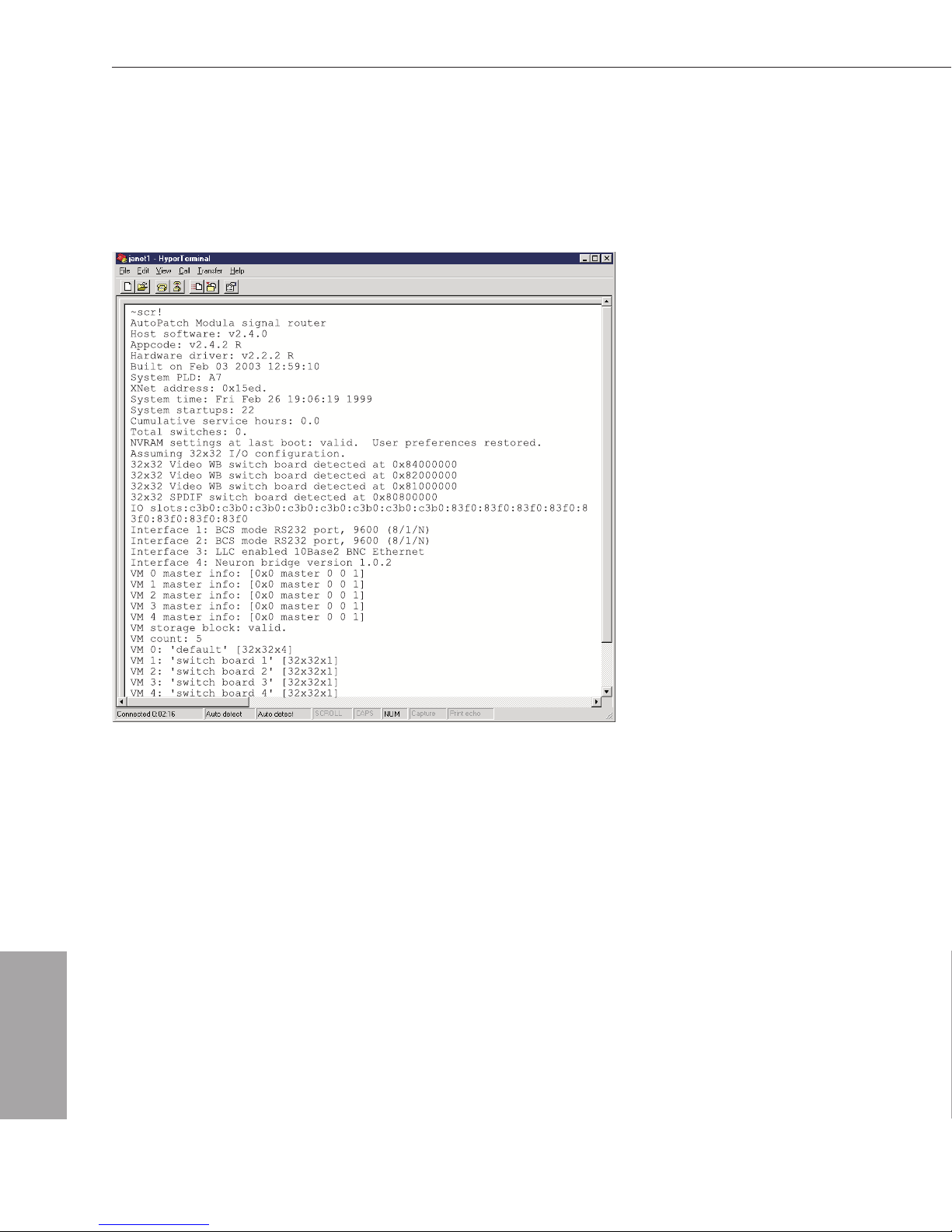
For startup diagnostic information, enter ~scr! If you need details
regarding items on the long splash screen or if errors are reported, call
AutoAssist (see Technical Support, page 7-6). See Figure 16 for an
example of a long splash screen for a 32x32 Modula.
Power & Startup
Figure 16: Long splash screen in HyperTerminal
6-4 Modula Installation & Setup

Executing a Test Switch
Execute a test switch to verify the system is working properly before
attaching all inputs and outputs. Aside from having signal cables
attached, the system is ready to perform switches when it ships from the
factory.
You can execute a test switch from the following:
Local control panel (CP-20 or CP-10)
ä
An external serial controller (computer, AMX, Crestron, etc.)
ä
via BCS (Basic Control Structure) commands
Test Switch
Note: Before executing a test switch, attach only the first two inputs
and the first two outputs as indicated in the AutoPatch “Modula
Connector Guide” located inside the back cover of this binder.
The local control panel test switch examples (CP-20 on page 7-2 and
CP-10 on page 7-4) route input (source) 2 to output (destination) 1 on
Level 0 (your system may have been programmed with a different level).
The BCS command test switch (see page 7-6) routes input 1 to output 2
on Level 0. Before executing these switches, make sure the first two
inputs and outputs are connected exactly as shown on the AutoPatch
“Modula Connector Guide.”
For additional information on options for executing switches, see the
Front Panel Operation or the Serial Control Operation section of this
binder.
Modula Installation & Setup 7-1

Test Switch
Executing a Test Switch
7.1 Executing a Test Switch Using
the CP-20 Control Panel
The following test switch routes Source (input) 2 : DVD #1 Rm 7
to Destination (output) 1 : Projector Exec Conf on level 0 (the default
level). Sources and Destinations can be named (labeled) using
N
X
Connect, see page 8-6 for more information. Before executing these
switches, make sure the first two inputs and the first two outputs are
connected exactly as shown on the AutoPatch “Modula Connector
Guide.”
You can return to the Main Menu screen at any time by choosing the
Main Menu command.
To execute a test switch using the CP-20 Control Panel:
1. At the Main Menu screen, choose the Change command.
Setup
System
www.autopatch.com
Change
Status
Macro
Adjust
Audio
The Select Source to Change screen appears, displaying the current
level and source options.
7-2 Modula Installation & Setup

Using the CP-20 Control Panel
2. Select Source 2 : DVD #1 Rm 7 by scrolling through the list with
the Control Dial (left is down; right is up).
3. Press the dial to enter.
The Change to Destination(s) screen appears, displaying the current
level and source, along with the destination options.
Test Switch
4. Press the dial to enter
1 : Projector Exec Conf (scrolling is not
necessary, since the first destination is ready to select).
The switch occurs as soon as the Control Dial is pressed (when the
line is dark, the switch is active).
Modula Installation & Setup 7-3
Test Switch
Executing a Test Switch
Note: The Control Dial functions as a toggle switch, activating and
deactivating destinations in the list each time it is pressed.
5. Choose the Source command to return to the Select Source to
Change screen to make additional test switches.
Or choose the Main Menu command to return to the Main Menu
screen.
If the switch did not execute properly:
Check all power switches to make sure the source and destination
q
devices are turned on.
Check all link and signal connections on the rear of the enclosure(s)
q
to make sure everything is physically set up correctly.
Attempt the switch again.
q
If the switch still does not work, call AutoAssist (see page 7-6).
7.2 Executing a Test Switch Using
the CP-10 Control Panel
The following test switch routes Input 2 to Output 1 on Level 0 (the
default level). Before executing these switches, make sure the first two
inputs and the first two outputs are connected exactly as shown on the
AutoPatch “Modula Connector Guide.”
To execute a test switch using the CP-10 Control Panel:
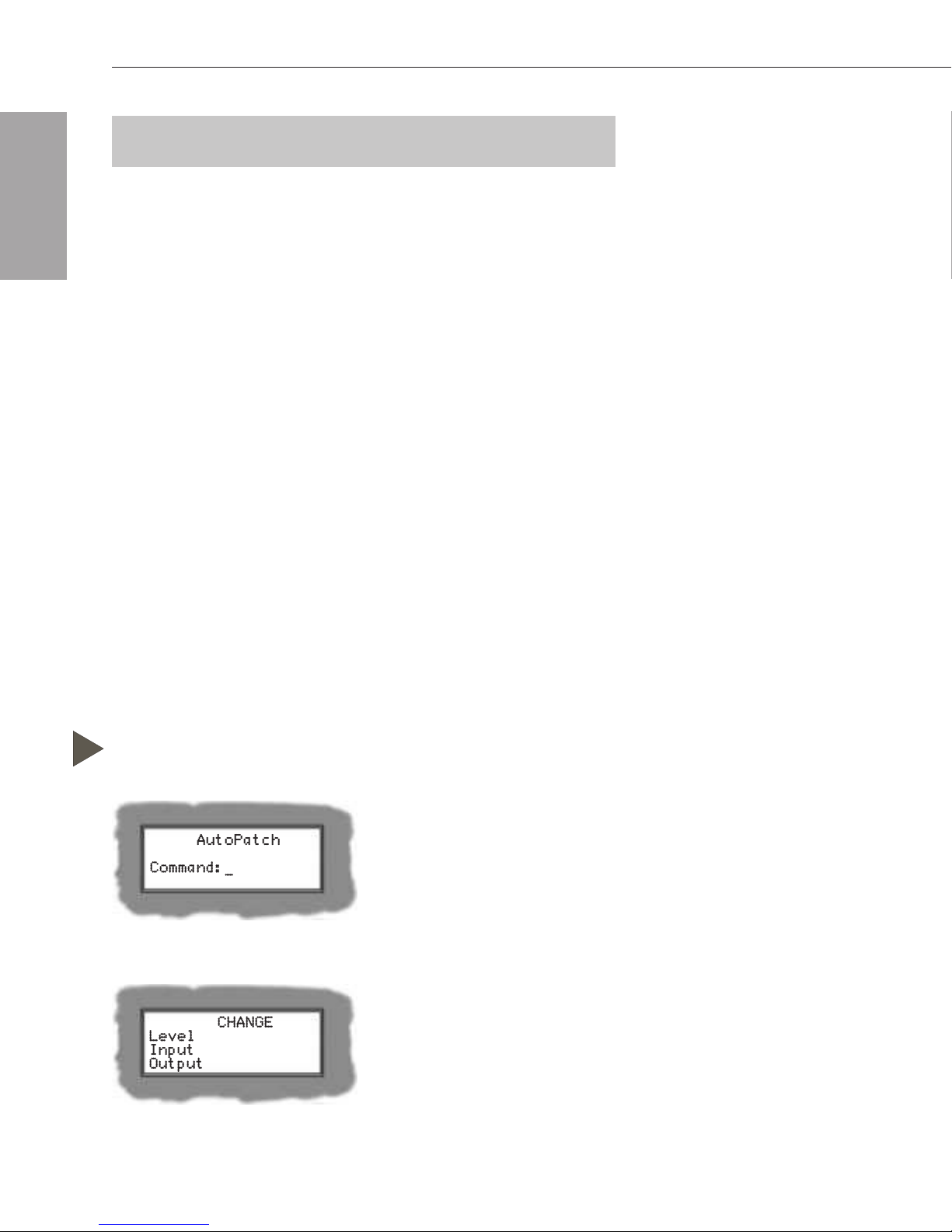
1. At the Command screen, press the Change key.
The Change screen appears.
7-4 Modula Installation & Setup
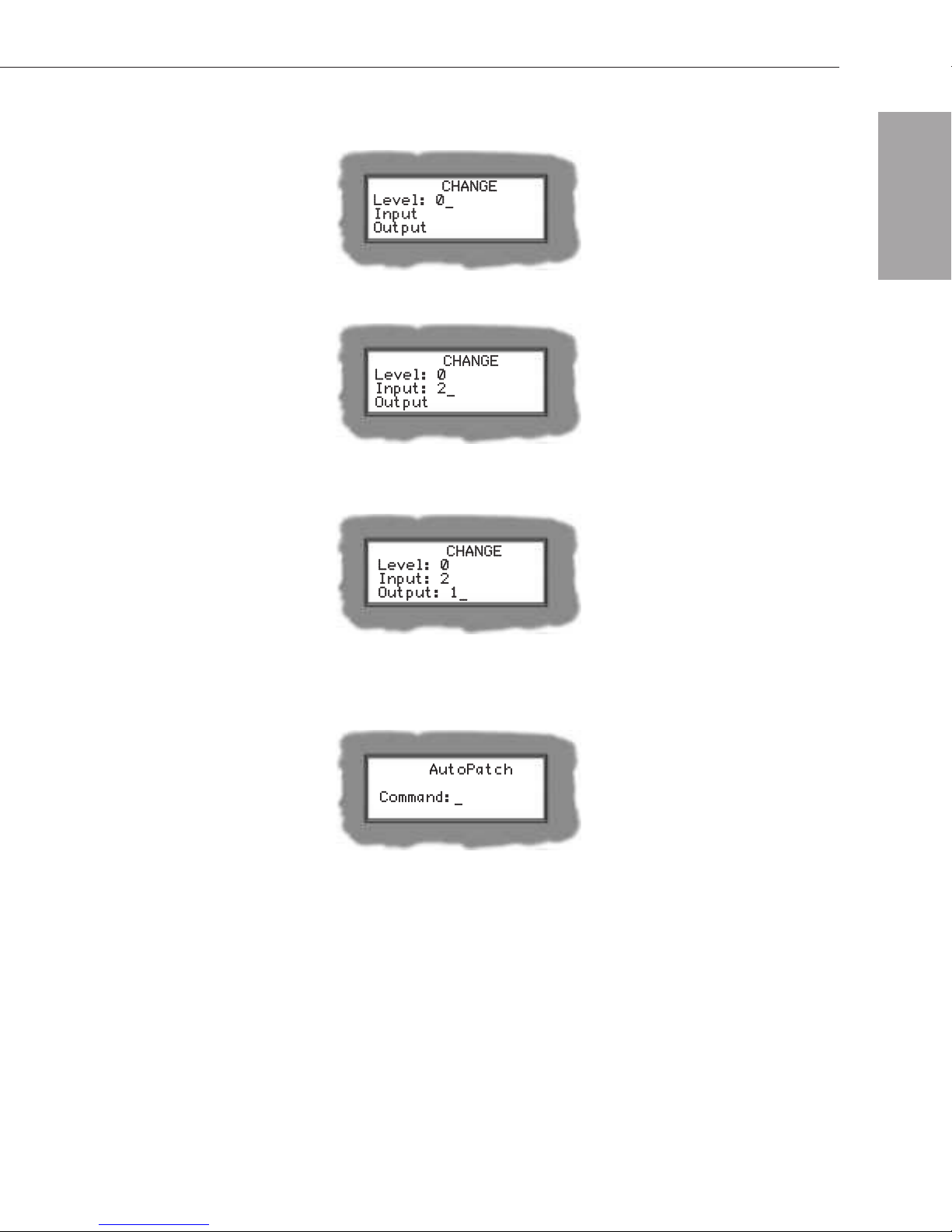
2. Press the Level key and enter “0”.
3. Press the Input key and enter “2.”
4. Press the Output key and enter “1.”
Using the CP-10 Control Panel
Test Switch
5. Press the Take key.
The signal is routed and the Command screen appears.
If the switch did not execute properly:
q
Check all power switches to make sure the source and destination
devices are turned on.
q
Check all link and signal connections on the rear of the enclosure(s)
to make sure everything is physically set up correctly.
q
Attempt the switch again.
If the switch still does not work, call AutoAssist (see page 7-6).
Modula Installation & Setup 7-5

Test Switch
Executing a Test Switch
7.3 Executing a Test Switch
Using BCS Commands
The following test switch routes Input 1 to Output 2 on Level 0 (the
default level). Before executing these switches, make sure the first two
inputs and outputs are connected exactly as shown in the “Modula
Connector Guide.” The system must be attached to a serial control device
(see Chapter 5) with a terminal emulation program (such as
HyperTerminal).
To execute a test switch, enter the following BCS command line:
CL0I1O2T
All command characters up to the “T” (Take) are automatically echoed
when accepted. If the command is successfully executed, the “T” will also
echo.
For a complete list of BCS commands and responses, see the Serial
Control Operation section of this binder.
If the switch did not execute properly:
Check all power switches to make sure the source and destination
q
devices are turned on.
q
Check all link and signal connections on the rear of the enclosure(s) to
make sure everything is physically set up properly.
q
Attempt the switch again.
If the switch still does not work, call AutoAssist (see below).
7.4 Technical Support
AutoPatch provides technical support 24 hours a day, 7 days a week
(except for U.S. holidays). Before calling technical support with a
question, please consult the Modula documentation set binder. If this
binder cannot fully answer your question, have your serial number ready
(located on the expansion plate to the right of the power receptacle on the
rear of the enclosure) and call your authorized AutoPatch dealer or call
AutoPatch AutoAssist at: (toll free for U.S. and Canada) 800-622-0246 or
(international) 509-235-2636. You can also reach us through our web site:
www.autopatch.com, or e-mail our AutoPatch Technical Support
Specialists at: support@autopatch.com
7-6 Modula Installation & Setup

Managing
Configuration Files
A configuration file is a text file that contains system configuration
information that has been previously downloaded to the CPU in your
matrix switcher before shipment. Each enclosure’s CPU references this
information during any type of switching operation. Unless you need to
modify your system, you will not need to use any of the software set that is
included in shipping. A copy of the configuration file (*.xcl) is in the
Configuration\APConfig\MyXCL folder on the AutoPatch Software and
Documentation CD ROM inside the front cover of this binder.
Configuration Files
The AutoPatch configuration software on the CD is X
graphical software program that can be used to modify and download
system configuration information.
If you lose your AutoPatch CD, either download X
AutoPatch web site (then from the Getting Started dialog box or from the
File menu select Discover System) or contact AutoAssist (see Technical
Support, page 7-6) to replace it. Make sure that you have your system’s
serial number ready when you call, so a copy of your original
configuration file can be sent.
To modify a configuration file using X
about the following topics, which are covered in this chapter:
ä
Conceptual overview
ä
Installing and launching X
ä
User Interface
ä
Opening and downloading a configuration file
N
Connect
N
Connect, you need information
N
Connect, a
N
Connect from the
ä
Modifying a configuration file
Modula Installation & Setup 8-1

Configuration Files
Managing Configuration Files
8.1 Conceptual Overview
The physical component(s) of a system can be a standalone matrix
switcher or multiple matrix switchers with or without additional
controllers. Opening a copy of the system’s configuration (.xcl) file with
N
X
Connect Configuration software allows you to use XNConnect’s four
basic functions:
Graphically displaying the content of the AutoPatch configuration
ä
file. This information is represented in two main views, the
“Hardware” tab view and the “Virtual Matrices” tab view.
Modifying the representations to reflect desired physical changes to
ä
the system.
Setting the desired values for configurable properties, when
ä
replacement or new components are added to the system.
Downloading the new configuration information to the system’s
ä
CPU(s).
8.2 Installing and Launching XNConnect
XNConnect is a graphical software program that can display the system’s
configuration and allows easy addition of local presets and modification
of other configuration information (see the X
assistance). X
N
Connect can also download the modified file to the
system.
Note: Use this software only if you need to change the configuration
information from the original specification.
To install X
N
Connect:
1. Close all other applications currently running on your PC.
2. Insert the AutoPatch Software and Documentation CD* into your
CD drive to start automatically.
If the CD does not autorun, explore the CD folders and double-click
on the setup.exe file.
3. Follow the directions in the subsequent dialog boxes in the
installation program.
N
Connect Help file for
*If you cannot locate the AutoPatch CD, either download X
from the AutoPatch web site (then from the Getting Started dialog box or
the File menu select Discover System) or have the AutoPatch product’s
serial number ready and contact Technical Support (see page 7-6).
8-2 Modula Installation & Setup
N
Connect
Installing and Launching XNConnect
4. Review the READme.txt file found on CD:\Configuration
\APConfig\ or after installation in the main installation folder. The
default location is C:\AutoPtch\Configuration Software<Version>.
N
To launch X
Connect:
1. From the Start menu, select Programs.
2. Select AutoPatch Applications (or any other file group you selected
during the install).
3. Select the Connect file group.
4. Select the Connect program.
N
The X
Connect program opens.**
Configuration Files
5. Open your configuration file, see page 8-5.
6. Connect the AutoPatch enclosure to your PC via the communication
ports using an RS-232 null modem cable.
**If your PC does not use Com 1, after step 4 open the Communication
menu, select the appropriate communication link (Serial Port or
Ethernet), select Change Comm Settings, and make the necessary
changes.
Modula Installation & Setup 8-3

Managing Configuration Files
8.3 User Interface
XNConnect displays information in two panes. The graphics are located
in the left pane and the properties of the currently selected graphic are in
the right pane. At the top of the left pane, you can access the different
graphical representation views from two tabs: Hardware and Virtual
Matrices. Hardware, such as enclosures and control panels, appear in the
Hardware view and existing virtual matrices appear in the Virtual
Matrices view. As you switch from view to view, the properties
displayed in the right pane automatically change to correspond to the
new graphics.
Highlighted Device
Configuration Files
Primary
Device
Properties
of Highlighted Device
Components of
the Primary Device
View of All Devices Connected
Using the XNNet Network
A variety of dialog boxes for modifying your system’s configuration file
are accessed through the menus. The menu options include topics such as
Modifying Serial Port Settings, Set Password Combo, Managing Boards,
Managing Virtual Matrices, and Managing Presets.
Note: If you have questions regarding an open dialog box, XNConnect
provides a context-sensitive Help file that can be accessed by pressing
the F1 key.
8-4 Modula Installation & Setup

Opening and Downloading a Configuration File
8.4 Opening and Downloading
a Configuration File
Start the process of modifying your configuration file by opening it in
N
X
Connect. After the modifications to the file are completed, the new
configuration information can be downloaded to your system.
N
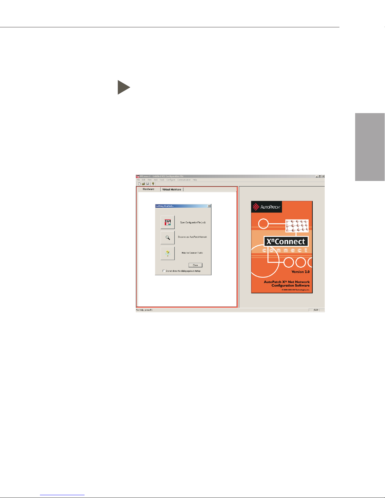
To open a configuration file in X
1. From the Getting Started dialog box, click Open Configuration File.
If the dialog box does not appear, from the File menu select Open.
2. Using the standard File Open dialog box, locate and open your XCL
(*.xcl) Input file. The default location is in the
C:\AutoPtch\Configuration Software<Version>\MyXCL folder.
3. Using Save As, make a duplicate copy of the file with a new name.
(We strongly recommend making a duplicate copy every time the file
is modified.)
4. Enter the desired modifications (see below) to the file copy.
To download the modified configuration file from X
system, from the Configure menu, select Configure All.
Caution: Depending on the modification, downloading the configuration
information may not be possible while the matrix switcher is operating.
See “Configure Menu Commands” in the Help file.
Connect:
N
Connect to your
Configuration Files
8.5 Modifying a Configuration File
Modifying a configuration file with XNConnect involves entering
information in one or a series of dialog boxes. A brief look at the Help
file Contents provides an overview of the possible modifications.
When modifying a configuration file, it is helpful to keep in mind the
following definition of a virtual matrix. A virtual matrix is a set of virtual
source (input) channels and destination (output) channels in which the
channels’ component signals (such as R, G, B, H, and V) can be grouped
into a single channel to permit the simultaneous switching of them as an
aggregate signal (RGBHV). Each component signal must have all sources
and destinations within the same physical matrix. The resulting single
channel constitutes a source or destination number for control purposes.
Modula Installation & Setup 8-5

Configuration Files
Managing Configuration Files
Note: If you have questions regarding a dialog box you have open,
N
X
Connect provides a context-sensitive Help file that can be accessed
by pressing the F1 key.
The remainder of this section focuses on three of the most common uses
N
for X
Connect, modifying labels, configuring local presets, and
modifying groupings (see the X
N
Connect Help file for more information,
or assistance with other configuration related tasks).
Modifying Source and Destination Labels
If your system has a graphical front panel (such as a CP-20), you can
customize the source and destination labels displayed on the LCD. See
N
the X
Connect Help file for more information on label and description
parameters.
To customize the labels:
1. In the Virtual Matrix view, select the channel you want to rename.
2. In the right pane, edit the text in the Label field and click Apply.
After downloading the new configuration file to the system, you must
clear the previous labels before the new labels will load (see the
Front Panel Operation section of this binder).
Configuring Local Presets
The process for configuring local presets takes you through three dialog
boxes that cover managing, naming, and modifying presets.
To name a new preset (in preparation for specifying preset
information):
1. In the Virtual Matrices view, select the targeted virtual matrix, and
from the Edit menu, select Manage Local Presets.
8-6 Modula Installation & Setup

Modifying a Configuration File
2. Click the Name New button.
The Name New Preset dialog box opens.
3. Enter a name (limited to eight characters) for the new preset.
(This step is required in order to create a new preset.)
4. Enter a description. (This step is optional.)
5. Click OK to add the newly named preset to the Existing Presets list
in the Manage Local Presets dialog box.
Configuration Files
6. Proceed to the next set of steps for modifying a preset in order to
specify information for the newly named preset.
To modify presets:
7. In the Manage Local Presets dialog box, select the new preset from
the Existing Presets box.
8. Click the Modify Preset button.
The Modify Preset dialog box opens.
9. Change preset information by selecting the field or button options
(see page 8-8 for details).
10. When done, click OK to return to the Manage Local Presets dialog
box.
Modula Installation & Setup 8-7

Configuration Files
Managing Configuration Files
Name (modify preset name) type a new name (eight character limit)
ä
in the Name field that is not an existing preset name.
Assign Switch select one available source channel and one or more
ä
available destination channels (multiple select by holding down the
control key).
Click the Assign Switch button.
The assignment will appear in the Assignment column of the
Destination Channels list.
Clear Source select a source channel that you want to clear.
ä
Click the Clear Source button.
All instances of the selected source will be cleared from the
Assignment column of the Destination Channels list.
Clear Destination select a destination channel(s) (multiple select by
ä
holding down the control key) that you want to clear.
Click the Clear Destination button.
The Source Channel(s) assigned to the destination(s) will be cleared
from the Assignment column in the Destination Channels list.
ä Disconnect select either a source channel or one or more destination
channels to be disconnected.
Click the Disconnect button.
Current source and destination disconnects are displayed in the
Disconnected Channels list on their respective sides of the Modify
Preset dialog box.
Caution: Disconnecting a source affects all destinations that the source
is connected to whether they are part of this preset or not.
Note: During a source disconnect, all previous assignments for that
source are cleared from the Assignment column of the Destination
Channels list.
ä
Reconnect select either a source or destination channel that has been
disconnected.
Click the Reconnect button.
The channel is now available again for assignments.
Note: Reconnecting does not re-establish previous presets.
8-8 Modula Installation & Setup

Modifying a Configuration File
To delete an existing preset:
1. In the Virtual Matrices view, go to the Edit menu and select Manage
Local Presets.
2. Select the preset from the Existing Preset list that you want to delete.
3. Click the Delete Preset button.
A message opens asking if you are sure you want to delete the preset.
4. Click OK to delete the preset and return to the Manage Local Presets
dialog box.
Note: Presets are not implemented until the modified configuration file
is downloaded to the system (see page 8-5).
Modifying Groupings
The process for modifying groupings takes you through two dialog boxes
that allow you to assign connectors individually to a single channel’s
signals or to a group of channels by pattern.
Configuration Files
Manage Virtual Matrix Groupings
Use the Manage Virtual Matrix dialog box as a central point from which
to assign signals to connectors, thereby creating virtual source and
destination channels (sets of signals that will switch together because
they have been grouped together). Even though you must click the
Accept Groupings button to accept the new groupings, they are not
implemented until the modified configuration file is downloaded to the
system (see page 8-5).
Modula Installation & Setup 8-9

Configuration Files
Managing Configuration Files
To specify connector groupings from the Virtual Matrix view:
1. From the Edit menu, select Manage Connector Groupings.
The Manage Virtual Matrix Groupings dialog box opens.
2. Click the Group by Pattern button to assign sequential or spanning
groupings of signals for connectors (see page 8-11).
Or
Click the Assign Individually button to assign signals to connectors
one at a time (see page 8-12).
After entering information in the newly opened window and clicking
OK, the Manage Virtual Matrix Groupings dialog box reopens with
the results displayed in the read-only box at the bottom. The tabs
allow viewing of each channel of grouped signals for both sources
and destinations.
3. Repeat as needed, using either method to assign additional
groupings.
Note: When all modifications have been made, click the Accept
Assignments button (at the bottom of the box) to save the groupings to
the virtual matrix or click the Cancel button to start over. Remember,
however, that the new groupings are not implemented until the modified
configuration file is downloaded to the system (see page 8-5).
Group Connectors by Pattern
The Group Connectors by Pattern dialog box allows you to group signals
with connectors in either a spanning or sequential pattern, thereby
creating a large number of virtual source and destination channels
simultaneously.
ä
Spanning pattern – select to create groupings with blocks of similar
signal types; for example, plug all the red in RGB into adjacent
connectors on the matrix.
ä
Sequential pattern – select to define groupings where each aggregate
signal is plugged in next to each other in the matrix.
8-10 Modula Installation & Setup

Modifying a Configuration File
Note: This dialog box can only be accessed from the Manage Virtual
Matrix Groupings dialog box; select Manage Connector Groupings from
the Edit menu after selecting the target virtual matrix.
Configuration Files
To specify details about the pattern:
1. Select the pattern type by clicking either the Spanning or Sequential
option button. (See pages 8-14 and 8-15 for pattern examples).
2. Select the channel type by clicking either the Sources Only or
Destinations Only button.
The destinations can mirror the sources by clicking the Mirror
Directions check box.
3. In the Starting Channel box, select the starting channel number that
you want if it is different from the next available channel that is
already displayed.
4. Enter the number of channels you want to create in the Number of
Channels to Create box.
You are now ready to group signals to create virtual channels.
To create signal groupings:
5. From the Available Signals list box, select a signal.
6. From the Enclosure list box in the middle of the dialog box, select
the enclosure in which you want the selected signal routed.
Modula Installation & Setup 8-11

Managing Configuration Files
7. From the Matrix list box, select the physical matrix on which this
signal will be switched.
8. From the Available Connectors list box, select the starting connector;
click the Assign Signal button.
The added signal appears in the Signals with Connector Groupings
box.
To remove a signal, select it, and then click the Remove
Signal/Connector button.
9. Continue assigning connectors until all the signals show up in the
Signals with Connector Groupings box.
Configuration Files
10. Click OK to enter the signal groupings and return to the
Manage Virtual Matrix Groupings dialog box.
11. To save, click the Accept Assignments button at the bottom of the
Manage Virtual Matrix Groupings dialog box.
Note: The new groupings are not implemented until the modified
configuration file is downloaded to the system (see page 8-5).
Assign Connectors Individually
The Assign Connectors Individually dialog box is used to modify the
connector assignments in a virtual matrix. Each channel of a virtual
matrix has a specific number of signals, and each signal has a
corresponding connector assignment. For each signal in a specific
channel, you may add or remove a connector assignment.
8-12 Modula Installation & Setup

Modifying a Configuration File
To access the Assign Connectors Individually dialog box:
1. In the Virtual Matrix View, select the virtual matrix for which you
want to make connector assignments.
2. From the Edit menu, select Manage Connector Groupings.
The Manage Virtual Matrix Groupings dialog box opens.
3. From the Select a Method section of the dialog box, click the
Assign Individually button.
The Assign Connectors Individually dialog box opens.
To assign connectors individually:
4. From the Current Channel list, select the channel where you want to
make connector assignments.
If no channels are available, click the Create New Channel button.
5. From the Select Channel Type section of the dialog box, click either
Source (input channels) or Destination (output channels).
6. Select the signal you wish to add from the Available Signals list.
7. From the Enclosure list box (if available), select the enclosure in
which you want to create the groupings.
8. From the Matrix list box (if available), select the physical matrix on
which this signal will be switched.
9. From the Connector list, select the connector you want to assign a
signal to and click the Assign Connector button.
The signal and its connector appear in the Signals with Connector
Assignments list.
Configuration Files
10. Continue to make assignments until all signals in all channels have
been given connector assignments. This ensures that the virtual
matrix will be valid.
11. Click OK to enter the connector assignments and return to the
Manage Virtual Matrix Groupings dialog box (connectors are
entered but not accepted; see step 12 and the following Note).
12. To save, click the Accept Assignments button at the bottom of the
Manage Virtual Matrix Groupings dialog box.
Note: The new groupings are not implemented until the modified
configuration file is downloaded to the system (see page 8-5).
Modula Installation & Setup 8-13
Managing Configuration Files
Any highlighted signal and connector can be removed by clicking the
Remove Connector button. The Clear All Sources button removes all
connector assignments for all channels of the currently selected channel
type (sources or destinations). This is useful for removing all connectors
and starting fresh with no assignments.
8.6 Grouping Pattern Examples
For switching purposes, connectors can be grouped in two basic patterns,
spanning and sequential. Explanations and examples of both follow.
Spanning Grouping Pattern Example
Configuration Files
A spanning pattern is the most common method of grouping connectors
for a Modula Distribution Matrix. Each of the standard signals in an
aggregate signal is assigned to a connector on an adjacent board.
In Figure 17, for example, the first channel of VM0 (audio follow video)
is composed of connectors 1, 5, 9, 13, 17, 21, and 25. This configuration
routes any of the four source channels of RGBHV with stereo audio to
any or all of the four destinations.
VM1 or VM2 breakaway switches can also be routed using the four
channels of RGBHV or four channels of stereo audio respectively. The
first channel of RGBHV breakaway is composed of connectors 1, 5, 9,
13, and 17. The first channel of stereo audio breakaway is composed of
connectors 21 and 25.
Figure 17: Connectors grouped in a spanning pattern
8-14 Modula Installation & Setup

Grouping Pattern Examples
Sequential Grouping Pattern Example
Although using a spanning pattern is more common for Modula
Distribution Matrix enclosures, a sequential pattern can be used to group
connectors. Each of the standard signals in an aggregate signal is
assigned to an adjacent connector on the same board.
In Figure 18, for example, the first channel of VM0 (audio follow video)
is composed of connectors 1, 2, 17, and 18. This configuration routes any
of the eight source channels of Y/c with stereo audio to any or all of the
eight destinations.
VM1 or VM2 breakaway switches can also be routed using the eight
channels of Y/c or eight channels of stereo audio respectively. The first
channel of Y/c breakaway is composed of connectors 1 and 2. The first
channel of stereo audio breakaway is composed of connectors 17 and 18.
Configuration Files
Figure 18: Connectors grouped in a sequential pattern
Modula Installation & Setup 8-15

Paralleling Inputs
The switching capability of the Modula Distribution Matrix can be
expanded by paralleling (also referred to as “splitting”) inputs. Normally
the input connectors on one enclosure can only route a signal to the
output connectors on that enclosure. However, connecting an input on
one enclosure to the corresponding input on a second enclosure with a
T-connector allows a source signal to be routed to all available output
connectors for that signal on both enclosures. By paralleling inputs on
two enclosures each with a 32x32 configuration, the set of configuration
possibilities expands to 32x64.
The source signal must be routed on different levels for each enclosure;
therefore, the system must be configured in X
are on different virtual matrices (levels).
Note: Splitting a signal more than four times requires a distribution
amplifier.
N
Connect so the enclosures
Paralleling Inputs
Modula Installation & Setup 9-1
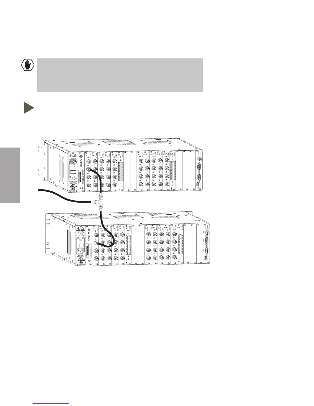
Paralleling Inputs
9.1 Paralleling Inputs
Caution: When video signal inputs are paralleled, the boards in the
enclosure connected to the source must be high impedance (Hi-Z) and
the boards in the last enclosure (the one terminating with a BNC
connector) must not be Hi-Z.
To parallel inputs between two enclosures:
1. Fasten a T-connector to the cable coming from the source (see
Figure 19).
Paralleling Inputs
Source
Cable
Figure 19: Connecting inputs for parallel control
2. Fasten one end of a signal cable, which is approximately 3” (7.6 cm)
long, to the T-connector and the other end to the input on the first
enclosure.
3. Fasten another short signal cable to the remaining end of the
T-connector and the corresponding input on the second enclosure.
The source is ready to switch to outputs on both enclosures.
9-2 Modula Installation & Setup

Controlling Paralleled Inputs
9.2 Controlling Paralleled Inputs
Basically, each split of the source signal is treated as a separate input
signal for control purposes. To control paralleled inputs, the system must
be configured in X
matrices (levels). Steps for executing switches on the CP-20, the CP-10,
and with BCS commands are provided below (status can be verified in a
similar manner). For additional control information, see the Front Panel
Operation or Serial Control Operation (BCS) section of this binder.
CP-20 Operation of Paralleled Inputs
To execute switches on paralleled inputs:
N
Connect so the enclosures are on different virtual
1. Select Change.
2. Select the level for which the first enclosure is configured.
3. Select the source (paralleled input) and the desired destination(s).
4. Repeat steps 1 through 3 for the second enclosure, using the level for
which it is configured, the source, and the desired destination(s).
CP-10 Operation of Paralleled Inputs
To execute switches on paralleled inputs:
1. Press the Change key.
2. Press the Level key and select the level for which the first enclosure
is configured.
3. Select the paralleled input (source) and the desired output(s).
4. Repeat steps 1 through 3 for the second enclosure, using the level for
which it is configured, the input, and the desired output(s).
BCS Operation of Paralleled Inputs
Paralleling Inputs
To execute switches on paralleled inputs:
1. Enter the command for the first enclosure using its level.
2. Enter the command for the second enclosure using its level.
Example:
CL0I2O#T
CL1I2O#T
Modula Installation & Setup 9-3

Adding Boards
Input and output boards can be added to a partially filled enclosure to
expand a system’s capabilities. Input and output boards increase an
enclosure’s possible signal routings. When you add boards to a Modula
enclosure (or remove them), normally you will not need to update the
system’s configuration information. If a new configuration file is
necessary, it is provided with the new boards and will need to be
downloaded to the system using X
recommend keeping a copy of the former configuration file for reference.
A Vertical Interval Sync board can also be added to an enclosure to
synchronize video signal switches with the output device’s refresh rate.
As part of the installation, the Vertical Interval Sync board must be
enabled by updating the system’s configuration file. Either of the two
methods on page 10-7 may be used.
N
Connect (see page 8-5). We
Adding Boards
Modula Installation & Setup 10-1

Adding Boards
10.1 Input and Output Boards
The number of input and output signals in an enclosure determines the
number of input and output boards. In an enclosure, signals are sent and
received through input or output connectors.
ESD Warning: To avoid ESD (Electrostatic Discharge) damage to
sensitive components, make sure you are properly grounded (see the
ESD Warning page inside front cover) before handling any internal
Modula materials.
To add an input or output board:
1. Turn off the enclosure.
2. Remove the plate covering the empty board expansion slot. Be sure
to use the correct slot (see the “Modula Connector Guide”). If the
board is installed in the wrong slot, signal routing is affected. The
board’s location must match the system’s configuration information.
If required, a new configuration file is sent with new boards.
Adding Boards
1
10
6
2
OUT
OUT
OUT
OUT
11
7
3
12
8
4
22
18
14
OUT
OUT
23
19
15
24
20
16
+
IO
T
AU
C
continued protection
against risk of fire,
replace only with sam
type and rating of fuse.
100-240VAC
50/60Hz 2A Max.
UL 60950
E177015
2
A
2
N - For
V
0
5
e
C
A
h
D
en
iv. of X
ey, W
01051901001PREC030001
A
N
U
T
S
echnolo
A
, 509-235
gies, In
-26
c.
36
1
10
6
2
IN
3
4
IN
IN
IN
11
7
12
8
22
18
14
IN
IN
23
19
15
24
20
16
21
17
13
9
5
+
21
17
13
9
5
Figure 20: Remove the plate that covers the empty board slot
3. Line up the board with the board guides that are on the top and
bottom of the board slot. Carefully push the board into the enclosure
until it snaps into place and the metal plate is flush with the back.
21
17
13
9
5
1
10
6
2
OUT
OUT
OUT
OUT
11
7
3
12
8
4
22
18
14
OUT
OUT
23
19
15
24
20
16
+
CAUTION - For
continued protection
against risk of fire,
replace only with same
type and rating of fuse.
100-240VAC
50/60Hz 2A Max.
UL 60950
E177015
V
0
5
2
A
2
C
A D
heney, W
iv. of XN
01051901001PREC030001
A U
Technologies, Inc.
SA
, 509-235-2636
1
10
6
2
IN
3
4
IN
IN
IN
11
7
12
8
22
18
14
IN
IN
23
19
15
24
20
16
21
17
13
9
5
+
STATUS
COMM
PORT 1 PORT 2
LINK
STATUS
COMM
PORT 1 PORT 2
LINK
Figure 21: Line up the board with guides and push until flush with the back
10-2 Modula Installation & Setup
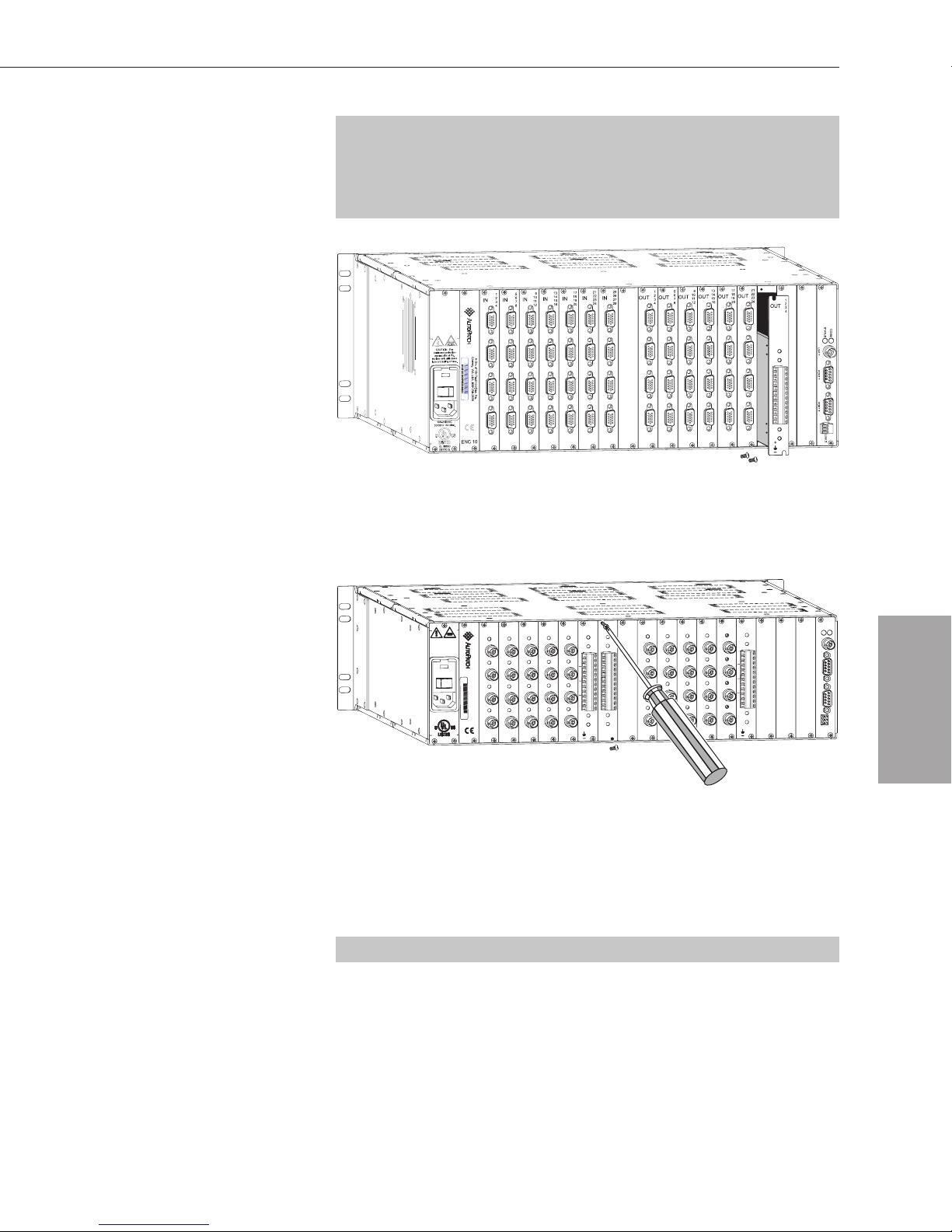
Input and Output Boards
Note: Normally boards for the Modula Series4 Distribution Matrices
are installed following steps 1 through 3; however, boards which do not
extend to the top of the face plate use the bottom board guide only (see
Figure 22).
Figure 22: Some Modula Series4 boards use the bottom guide only
4. Insert the screws into the holes on the connector assembly and
tighten the screws until they are snug.
1
10
6
2
OUT
OUT
OUT
OUT
11
7
3
12
8
4
22
18
14
OUT
OUT
23
19
15
24
20
16
PORT 1 PORT 2
+
LINK
CAUTION - For
continued protection
against risk of fire,
replace only with same
type and rating of fuse.
100-240VAC
50/60Hz 2A Max.
UL 60950
E177015
V
0
5
2
A
2
C
A
h
D
e
n
iv
e
. o
01051901001PREC030001
y
, W
f X
A
N
U
T
S
e
c
A
h
, 5
n
o
0
lo
9
-2
g
ie
3
s
5
, In
-2
63
c
.
6
1
10
6
2
IN
3
4
IN
IN
IN
11
7
12
8
22
18
14
IN
IN
23
19
15
24
20
16
21
17
13
9
5
+
21
17
13
9
5
Figure 23: Insert and tighten screws until they are snug
5. Attach the cables to the connectors; see the appropriate chapter(s) in
the Boards & Specifications section of this binder.
6. Reapply power and turn on the enclosure.
Note: This procedure can also be modified for removing boards.
STATUS
COMM
Adding Boards
Modula Installation & Setup 10-3

Adding Boards
10.2 Vertical Interval Sync Board
A Vertical Interval Sync board (VI Sync board) gives the Modula
complete vertical interval synchronization switching capability. The
VI Sync board uses a master sync signal by separating the sync from an
input signal (such as station master, blackburst, or composite video
input).
Each enclosure in a Modula can hold one VI Sync board. You may want
a VI Sync board in each enclosure that switches video signals. If the
system was originally ordered with VI Sync boards, they are already
installed in the enclosures.
Termination Load Jumper
Vertical Interval Sync boards are shipped with the termination load
jumper (J1) set to the “off” position (high impedance). If the house sync
generator does not have a termination load of 75 ohms, this jumper must
be set to the “on” position to internally set a 75 ohm load (see Figure 24).
Adding Boards
P1
P2
P3
Off – High Impedance
Figure 24: Termination load jumper (J1) positions
On – 75 Ohm Load
10-4 Modula Installation & Setup

Vertical Interval Sync Board
External Connections
Each of the three BNC-type connectors (see Figure 28 on page 10-6) on
a Vertical Interval Sync board serves a different function.
P1 – Local Sync Input: This connector is designed to be connected
ä
by cable to the local sync output (P3) of another VI Sync board to
switch TTL-level signals. This connection allows enclosures to be
switched on command from the master enclosure.
P2 – External Sync Input: This connector accepts any of the
ä
following signal types:
NTSC composite video
Composite sync type of synchronization
RGBS group member that contains sync information
Blackburst generator
P3 – Local Sync Output: This connector is designed to be
ä
connected by cable to the local sync input (P1) of another VI Sync
board to switch TTL-level signals. This connection allows
enclosures to be switched on command from the master enclosure.
Installing a VI Sync Board
ESD Warning: To avoid ESD (Electrostatic Discharge) damage to
sensitive components, make sure you are properly grounded (see the
ESD Warning page inside the front cover) before handling any internal
Modula materials.
To add a Vertical Interval Sync board:
1. Make sure all enclosures receiving a VI Sync board are turned off.
2. Remove the plate that covers one of the expansion slots.
21
17
13
9
5
1
10
6
2
OUT
OUT
OUT
OUT
11
7
3
12
8
4
22
18
14
OUT
OUT
23
19
15
24
20
16
PORT 1 PORT 2
+
CAUTION - For
continued protection
against risk of fire,
replace only with same
type and rating of fuse.
100-240VAC
50/60Hz 2A Max.
UL 60950
E177015
V
0
5
2
A
2
C
A
h
D
eney, W
iv. of X
01051901001PREC030001
A U
N
T
S
echn
A
, 50
olo
9-235-263
gies, Inc.
6
1
10
6
2
IN
3
4
IN
IN
IN
11
7
12
8
22
18
14
IN
IN
23
19
15
24
20
16
+
21
17
13
9
5
Adding Boards
STATUS
COMM
LINK 2
Figure 25: Remove the plate from an expansion slot
Modula Installation & Setup 10-5

Adding Boards
3. Line up the board with the board guides that are on the top and
bottom of the board slot. The board has the correct end up when the
back of the connectors are to the right of the board. Carefully push
the board into the enclosure until it snaps into place and the metal
plate is flush with the back.
21
17
13
9
5
21
17
13
9
5
CAUTION - For
continued protection
against risk of fire,
replace only with same
type and rating of fuse.
100-240VAC
50/60Hz 2A Max.
UL 60950
E177015
1
10
6
2
IN
IN
IN
IN
V
0
5
2
A
2
Cheney, WA USA, 509-235-2636
A Div. of XN Technologies, Inc.
01051901001PR
EC030001
11
7
3
12
8
4
22
18
14
IN
IN
23
19
15
24
20
16
+
Figure 26: Line up the board with guides and push until flush with the back
1
10
6
2
T
U
O
3
4
U
O
T
U
O
UT
O
11
7
12
8
22
18
14
UT
O
UT
O
T
23
19
15
24
20
16
+
STATUS
COMM
PORT 1 PORT 2
LINK
Adding Boards
4. Insert the screws into the holes on the connector assembly and
tighten the screws until they are snug.
1
10
6
2
OUT
OUT
OUT
OUT
11
7
3
12
8
4
22
18
14
OUT
OUT
23
19
15
24
20
16
+
CAUTION - For
continued protection
against risk of fire,
replace only with same
type and rating of fuse.
100-240VAC
50/60Hz 2A Max.
UL 60950
E177015
V
0
5
2
A
2
Cheney, W
A Div. of XN Technologies, Inc.
01051901001PREC030001
A USA, 509-235-2636
1
10
6
2
IN
3
4
IN
IN
IN
11
7
12
8
22
18
14
IN
IN
23
19
15
24
20
16
21
17
13
9
5
+
21
17
13
9
5
Figure 27: Insert the screws and tighten until snug
5. Fasten the house sync or blackburst cable to the P2 connector.
21
17
13
9
5
1
10
6
2
OUT
OUT
OUT
OUT
11
7
3
12
8
4
22
18
14
OUT
OUT
23
19
15
24
20
16
+
CAUTION - For
continued protection
against risk of fire,
replace only with sam
type and rating of fuse.
100-240VAC
50/60Hz 2A Max.
UL 60950
E177015
0
5
2
A
2
V
e
01051901001PREC030001
1
10
6
2
IN
3
4
C
A
h
D
e
n
iv. o
ey
, W
f X
A
N
U
T
S
e
ch
A
, 5
n
o
09
lo
-23
g
ie
s, In
5-26
c.
3
6
IN
IN
IN
11
7
12
8
22
18
14
IN
IN
23
19
15
24
20
16
+
21
17
13
9
5
STATUS
COMM
PORT 1 PORT 2
LINK 2
STATUS
COMM
LINK 1
PORT 1 PORT 2
P1 Input -- Local Sync
P2 Input -- External Sync
P3 Output -- Local Sync
LINK 2
Figure 28: Fasten house sync or blackburst cable to P2
10-6 Modula Installation & Setup

Vertical Interval Sync Board
6. (Optional) Verify system recognition of the VI Sync board (see the
first set of steps below).
7. (Required) Enable the VI Sync board by updating the configuration
file (see the second set of steps below).
Verifying System Recognition of the VI Sync Board
If you want to verify system recognition of the VI Sync board, use an
external serial control device (PC, AMX, Crestron, etc.) with a terminal
emulation program (such as HyperTerminal).
To verify the system’s response:
1. Reapply power to all enclosures with video boards in the system.
2. Enter ~scr! in HyperTerminal.
3. Check the splash screen.
Output slots: [[...................text will vary according to boards in system.................]]
Sync board detected: checking for sync signal...ok. Sync switching enabled.
Interface 1: BCS mode RS232 port, 9600 (8/1/N)
Enabling the VI Sync Board
To complete installation, the VI Sync board must be enabled using one of
the following two methods.
N
If the original configuration file has not been modified, use X
to download the new file which shipped with the board (see page 8-5).
The new file will automatically enable the VI Sync board for the system.
If the original configuration file has been modified and you do not want
to replace it, follow the steps below.
N
To enable a VI Sync board using X
1. Open the configuration file in X
Connect:
N
Connect (see page 8-5).
2. In the Virtual Matrix view, right click the virtual matrix, and choose
Assign Signals from the shortcut menu.
The Assign Virtual Matrix Signals dialog box opens.
Connect
Adding Boards
Modula Installation & Setup 10-7

Adding Boards
3. Click the Vertical Interval Sync check box to enable the VI Sync
board.
4. Click OK.
Vertical Interval Sync
Adding Boards
5. Connect the enclosure to your PC via the serial ports.*
6. From the Configure menu, select Configure All.
All parts of the virtual matrix will now switch on a vertical interval.
*If your PC does not use Com 1, open the Communication menu and
select Change Comm Settings to change the PC serial port information.
10-8 Modula Installation & Setup

This index only includes references to the Installation & Setup section of this
binder. The Control Panel Operation, Serial Control Operation, and some of
the Enclosure (Board Set) Supplements have their own indexes. If you cannot
find what you are looking for here, please check the other sections.
Index
A
AC line conditioner 6-1
AC power 2-1
adding boards
configuration files 10-1
input and output boards 10-2
Vertical Interval Sync 10-5
Warning, ESD 10-2, 10-5
airflow restriction prevention 2-2
ambient temperature 2-2
applying power
see startup
attaching
external controller 5-1
inputs and outputs 4-1
link cable 3-2, 3-3
AutoAssist 7-6
B
BAUD rate settings 5-3
BCS (Basic Control Structure)
external controller 5-1
parallel inputs 9-3
test switch 7-6
boards, adding 10-1
C
cable
attaching 2-5, 10-3
Caution, correct enclosure 3-1
link 2-3, 3-2, 3-3
signal 4-2
cable continued
parallel inputs 9-2
sync 10-6
Caution
cable correct enclosure 3-1
disconnecting an input 8-8
Double Pole/Neutral Fusing fuses 1-5
heat producing equipment 2-2
overheating 2-2
paralleling inputs 9-2
power switch 2-3
redundant power supplies 1-6
circuit overloading 2-3
Command screen
see CP-10 Control Panel
communication (serial) settings 5-3
N
configuration file, X
see also XNConnect
adding boards 10-1
configure local presets 8-6
downloading 8-5
enable VI Sync board 10-7
graphical representation 8-2
Help file 8-4, 8-5
labels (names) 8-6
location 8-1
modify file 8-5
modify groupings 8-9
modify presets 8-7
new boards 10-2
open 8-5
virtual matrix, definition 8-5
Connect
Modula Installation & Setup

Index
connector guide 4-2
connectors
assigning 8-12
Ethernet 3-1 to 3-3, 5-1
external control devices 1-4
external, VI sync boards 10-5
grouping 8-9, 8-14, 8-15
input and output 1-4, 10-2
serial 5-1 to 5-3
terminating 2-5, 3-2, 3-3
N
Net 5-1
X
control slots
see expansion slots
CP-10 Control Panel
Command screen 6-2, 7-4
executing a test switch 7-4
parallel inputs 9-3
startup 6-2
CP-20 Control Panel
executing a test switch 7-2
parallel inputs 9-3
startup 6-2
Ethernet ports 3-1
executing test switch
see test switch
expansion slots
description 1-4
input/output boards, adding 10-2
Vertical Interval Sync, adding 10-5
external controllers
attaching 5-2
BAUD rate settings 5-3
communication protocols 5-1
F
fuse
Caution 1-5
location 1-5
G
grounding 2-3, 6-1
Groupings, modifying
N
see X
Connect
H
CPU (Central Processing Unit)
components 1-4
serial controllers, attaching 5-2
N
Net port illus. 1-4
X
D
disconnecting an input, Caution 8-8
Double Pole/Neutral Fusing, Caution 1-5
E
ears, rack 2-4
earthing 2-3, 6-1
e-mail, technical support 7-6
enclosure 1-2
linking 3-1
rack installation 2-3
rear illus. 1-3
site recommendations 2-2
ESD (electrostatic discharge)
Warning, adding boards 10-2, 10-5
Ethernet link connectors 3-1
hazard precautions 2-2
heat-producing equipment, Caution 2-2
Help file 8-4, 8-5
humidity 2-1
HyperTerminal 6-3, 7-6, 10-7
I
inputs and outputs
attaching 4-1
connector types 4-2
disconnecting an input, Caution 8-8
installation procedure 2-1
L
labels (names) 8-6
LCD screen
viewing angle 2-2
linking enclosures 3-1 to 3-3
local presets
see presets
Modula Installation & Setup

M
redundant power supplies (RPS)
mechanical loading 2-2
Modula Series4 1-3, 10-3
multi-enclosure system 3-1
O
outputs
see inputs and outputs
overheating, Caution 2-2
overloading circuits 2-3
P
paralleling inputs
Caution, high impedance 9-2
control, CP-20, CP-10, BCS 9-3
instructions illus. 9-2
purpose 9-1
pinout illus. 5-2
power connector 1-5
power cord, Caution 2-3
power receptacle 1-5, 6-1
power supply 1-5
power supply, redundant 1-6
power switch
Caution 2-3
illus. 1-5
power, applying 6-1, 6-2
power cords 6-1
standard international power sources
6-1
see also startup
presets
configure 8-6
delete 8-9
modify 8-7
R
rack ears 2-4
rack installation 2-3
Caution 1-6
indicator illus. 1-6
RS232 pin diagram 5-2
RS422 pin diagram 5-2
S
serial cables
pinout illus. 5-2
serial communication 5-3
serial connectors 5-2
serial controller
attaching 5-2
BCS commands 5-1, 7-6
definition 5-2
startup 6-3
serial ports
communication protocols 5-1
location illus. 1-4
Series4, Modula 1-3, 10-3
sequential grouping pattern
configuration 8-11
example 8-15
shipping boxes 1-1
signal
cables, attaching 4-2
cables, paralleling 9-2
site recommendations 2-2
spanning grouping pattern
configuration 8-11
example 8-14
specifications
AC power 2-1
dimensions 2-1
frequency 2-1
fuse 2-1
humidity 2-1
weight 2-1
splitting inputs
see paralleling inputs
Modula Installation & Setup

Index
startup
applying power 6-2
Caution 2-3
control device illus. 6-4
CP-10 Control Panel 6-3
CP-20 Control Panel 6-2
serial control device 6-3
surge protector 2-3, 6-1
switch
see also test switch
Sync board, Vertical Interval
enabling, configuration files 10-7
external connections 10-5
function 10-1, 10-4
installing illus. 10-5
termination load jumper 10-4
verifying system recognition 10-7
sync connectors
external connections 10-5
illus. 10-6
T
T-connectors 2-3, 3-2, 3-3, 9-1
Technical Support 7-6
temperature, Caution 2-2
termination connector, Ethernet port 2-3,
3-2, 3-3
termination load jumper 10-4
test switch
BCS commands, using 7-6
executing 7-1
using CP-10 Control Panel 7-4
using CP-20 Control Panel 7-2
tools for installation
general 1-2
rack installation 2-3
U
V
Vertical Interval Sync board 10-4 to 10-8
virtual matrix, definition 8-5
W
Warning
adding boards, ESD 10-2, 10-5
web site 7-6
X
XNConnect
see also configuration files
adding boards 10-1
conceptual overview 8-2
configure local presets 8-6
download configuration file 8-5
enable VI Sync board 10-7
functions 8-2
Help file 8-4, 8-5, 8-6
installation 8-2
labels 8-6
launch 8-3
modify configuration
file 8-5
modify groupings 8-9
open configuration file 8-5
panes and views 8-4
presets 8-6 to 8-9
user interface 8-4
virtual matrix, definition 8-5
N
Connect, dialog boxes
X
Assign Connectors Individually 8-12
Assign Virtual Matrix Signals 10-7
Group Connectors by Pattern 8-10
Help file 8-6
Manage Local Presets 8-6
Manage Virtual Matrix Groupings 8-9
Modify Preset 8-7
Name New Preset 8-6
N
Net
X
unpacking
shipping boxes, contents 1-1
tips 1-2
Communication Library 5-1
external controllers, attaching 5-1
port illus. 1-4
Modula Installation & Setup


Contents
Chapter 1 – Introducing the CP-20A
CP-20A Control Panel ....................................................1-2
Graphic LCD .........................................................1-2
Dynamic Menu Area..................................................1-2
Dynamic Menu Keys..................................................1-3
Function Key.........................................................1-3
Take Key ............................................................1-3
Technical Support ........................................................1-4
Chapter 2 – Executing Switches
Executing Switches – Selecting Input First ..................................2-2
Executing Switches – Selecting Output First.................................2-4
Changing the Virtual Matrix ...............................................2-7
Chapter 3 – Disconnecting Switches
Disconnecting an Input ...................................................3-2
Disconnecting an Output ..................................................3-4
Chapter 4 – Verifying Signal Status
Verifying Input Status .....................................................4-1
Verifying Output Status ...................................................4-3
Chapter 5 – Executing Presets
Defining Global Presets ...................................................5-2
Executing Global Presets..................................................5-4
Chapter 6 – Adjusting Audio
Adjusting Volume.........................................................6-2
Adjusting Digital Input Gain ................................................6-4
Local Presets ........................................................5-1
Global Presets .......................................................5-1
CP-20A Control Panel Operation

Contents
Chapter 7 – Adjusting LCD Contrast
Adjusting Contrast – Main Menu ..........................................7-1
Adjusting Contrast – Setup ...............................................7-2
Chapter 8 – Reloading Configuration File
Chapter 9 – Checking Software Version
Checking Software – Setup ...............................................9-1
Setup Version Screen ................................................9-2
Chapter 10 – Installing a CP-20A Remote
General Specifications...................................................10-1
Rear View .............................................................10-1
Connecting to an AutoPatch Router ......................................10-2
Communication Cable Specifications..................................10-2
Applying Power .........................................................10-3
Power Requirements................................................10-3
Rack Installation ........................................................10-4
Linking Multiple Panels ..................................................10-5
Power Requirements................................................10-5
Appendix A – System Error Codes
Most Common System Error Codes........................................A-1
Troubleshooting..........................................................A-2
Technical Support ........................................................A-2
Index
CP-20A Control Panel Operation
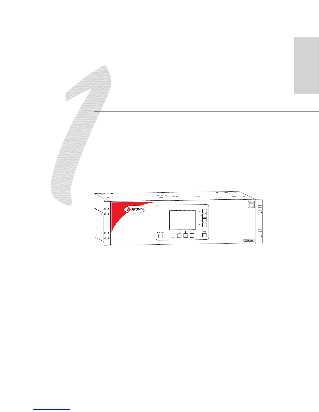
Introducing the CP-20A
This section is specifically written for AutoPatch enclosures with either a front or
remote CP-20A Control Panel. The CP-20A is used for controlling the system’s
switches and system attributes. Although control panels are optional, we
recommend one per system for system verification, redundant control, and
troubleshooting.
Figure 1 illustrates an Optima Distribution Matrix with a CP-20A Control Panel.
Other models may vary slightly in appearance.
Introduction
Figure 1: Front view of an Optima with a CP-20A Control Panel
Note: AutoPatch enclosures can also be controlled using BCS (Basic Control
Structure) commands transmitted through an external controller; see the BCS
Serial Control Protocol or Serial Control Operation section of this binder.
AutoPatch control software can also be used to control an AutoPatch system;
see the AutoPatch Software & Documentation CD for more information.
CP-20A Control Panel Operation 1-1
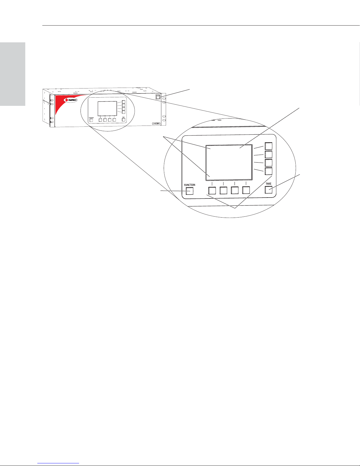
Introducing the CP-20A
CP-20A Control Panel
A CP-20A Control Panel has a graphic LCD with a dynamic menu area,
dynamic menu keys, a Function key, and a Take key.
Introduction
Power Indicator (or LED System Indicators)
Graphic LCD
Dynamic Menu Area
Take Key
Function Key
Dynamic Menu Keys
Figure 2: Close-up view of a CP-20A Control Panel
Graphic LCD
An LCD with a backlight displays instructions and selection entry fields. The
backlight automatically turns off after 15 minutes of inactivity. Press any key
to reactivate the light.
Note: To adjust the contrast of the LCD, see Chapter 7, “Adjusting LCD
Contrast.”
Dynamic Menu Area
The menu displays different command options across the bottom of the LCD,
depending on which screen is active. These options can be accessed using the
corresponding dynamic menu keys. The menu options are multilevel with the
ability to display custom input (source) and output (destination) names (labels).
The default channel name (e.g., O_Ch:0003 for Output 3) appears unless the
name has been modified in the configuration file* using X
N
Connect (see
Chapter 8 of the Installation & Setup section of this binder).
* The configuration file (.xcl file) contains routing and control information for
a system and is modified with X
Both the configuration file and X
N
Connect, which graphically displays the file.
N
Connect are on the AutoPatch Software &
Documentation CD.
1-2 CP-20A Control Panel Operation

CP-20A Control Panel
Dynamic Menu Keys
The keys select commands and settings. Each menu key lines up with a different
section of the dynamic menu area. The four keys across the bottom allow you to
select from the corresponding commands across the lower part of the screen.
The four keys on the right side of the LCD are used to scroll through lists, adjust
sliders, select an action, or return to the previous screen. The associated
commands on the right side of the Dynamic Menu Area vary by screen and
include the following:
Back key – Use to return to the last screen. This key will not undo a
q
completed operation.
Arrow keys – Use to scroll through lists and adjust sliders. When scrolling,
q
press and hold an arrow key to increase scrolling speed. When at the bottom
of a list, press the down key to access the top of the list. When at the top of a
list, press the up key to access the bottom of the list. Scrolling from the
bottom of a list may sometimes be more efficient depending on the matrix
size.
Introduction
Select key – Use to enter a selection. This key will not execute operations.
q
Function Key
The Function key accesses the Main Menu screen. From the Main Menu, the
Function key accesses additional menu options. From any other screen, it returns
to the Main Menu.
Take Key
The Take key functions much like the Enter key on a computer keyboard.
Pressing the Take key instructs the system to execute a selected operation. Prior
to pressing the Take key, the individual operation component(s) must be selected
by pressing the Select key.
CP-20A operations combine the following four basic tasks:
To choose a command, press the dynamic menu key along the bottom that
corresponds with the command you want to choose.
To locate values for fields (such as virtual matrix, input, output, and preset
values), press the dynamic menu keys on the right that correspond to the arrows.
To enter a selection, press the Select key. (The key that corresponds to the
Select option on the dynamic menu area is found on the right.)
To execute an operation, press the Take key.
CP-20A Control Panel Operation 1-3

Introduction
Introducing the CP-20A
Technical Support
For questions concerning CP-20A operations, note the specific information
(including error or warning messages) and contact AutoAssist.
AutoPatch provides technical support 24 hours a day, 7 days a week (except for
U.S. holidays). Before contacting technical support with a question, please
consult the product documentation. If this binder cannot fully answer your
question, have your serial number ready and contact your authorized AutoPatch
Dealer or AutoPatch AutoAssist. (The serial number is normally located on the
rear of the enclosure or remote panel; see also the Installation & Setup section of
this binder.)
AutoAssist Contact Information
Toll-free U.S. and Canada – 800-622-0246
ä
International – 509-235-2636
ä
Website – www.autopatch.com
ä
Email – support@autopatch.com
ä
1-4 CP-20A Control Panel Operation

Executing Switches
A switch is an active connection between an input (source) device and one or
more output (destination) devices. The signals routed in a switching operation are
individual signals or groups of individual signals coming through the connectors
on the rear of an enclosure. Executing a preset is a quick way to execute multiple
switches at a time. For information on presets, see page 5-1.
Switches are executed on the default virtual matrix unless otherwise specified.
When specifying a virtual matrix, be sure it includes all the signals you want to
route. The number of the virtual matrix (VM) that operations are currently being
performed on is displayed in the upper-right of the display. If you need to change
the virtual matrix, see “Changing the Virtual Matrix” on page 2-7.
You can return to the Main Menu screen at any time by pressing the Function
key.
Note: In each switch command, you can enter multiple output signals, but only
one input signal. However, you must select the input first in order to select
multiple outputs. The Take key must be pressed for the switch operation to
execute.
Executing Switches
CP-20A Control Panel Operation 2-1

Executing Switches
Executing Switches
Executing Switches – Selecting Input First
The example below routes Input 33: Satellite Dish to
Output
To execute a switch:
1. At the Main Menu screen, choose the Change command.
6: Reception Monitor on Virtual Matrix 0.
If the Change command is not available, press the Function key to view
additional Main Menu options.
High Performance
Signal Routing
CHANGE STATUS DISC AUDIO
The Change Input screen appears, displaying the available input options.
CHANGE INPUT:__ VM:0
1 : Reception Mic
2 : Reception Cam
3 : Reception DVD
4 : Mic #1 Control Rm
5 : Mic #2 Control Rm
6 : Mic #3 Control Rm
7 : VCR #1 Control Rm
8 : VCR #2 Control Rm
9 : VCR #3 Control Rm
10 : DVD #1 Control Rm
11 : DVD #2 Control Rm
V M OutputInput
2. Locate Input
33: Satellite Dish by scrolling through the list using
Back
Select
the arrow keys. (Press and hold an arrow key to scroll quickly.)
CHANGE INPUT:__ VM:0
23 : Podium Cam Mtg Rm A
24 : Audience Cam Mtg Rm A
25 : Tape Deck Mtg Rm A
26 : Main Mic Mtg Rm A
Audience Mic Mtg Rm A
27 :
28 : Podium Cam Mtg Rm B
29 : Audience Cam Mtg Rm B
30 : Tape Deck Mtg Rm B
31 : Main Mic Mtg Rm B
Audience Mic Mtg Rm B
32 :
33 : Satellite Dish
V M Output
Input
Back
Select
2-2 CP-20A Control Panel Operation

Selecting Input First
3. Press the Select key.
The Change Output screen appears, displaying the available output options.
CHANGE OUTPUT:__ Input:33 VM:0
1 : Main Control Monitor
2 : Codec Control Rm
3 : Monitor 1 Control Rm
4 : Monitor 2 Control Rm
5 : Monitor 3 Control Rm
6 : Reception Monitor
7 : Reception Speakers
8 : Lobby Monitor
9 : Main Monitor Rm A
10 : Audience Monitor Rm A
11 : Podium Monitor Rm A
Back
Select
Note: If other outputs are already routed to the selected input, they are
highlighted on the Change Output screen.
Executing Switches
4. Locate Output
6: Reception Monitor by scrolling through the list using
the arrow keys.
CHANGE OUTPUT:__ Input:33 VM:0
1 : Main Control Monitor
2 : Codec Control Rm
3 : Monitor 1 Control Rm
4 : Monitor 2 Control Rm
5 : Monitor 3 Control Rm
6 : Reception Monitor
7 : Reception Speakers
8 : Lobby Monitor
9 : Main Monitor Rm A
10 : Audience Monitor Rm A
11 : Podium Monitor Rm A
5. Press the Select key.
Output
CHANGE OUTPUT:__ Input:33 VM:0
1 : Main Control Monitor
2 : Codec Control Rm
3 : Monitor 1 Control Rm
4 : Monitor 2 Control Rm
5 : Monitor 3 Control Rm
6 : Reception Monitor
7 : Reception Speakers
8 : Lobby Monitor
9 : Main Monitor Rm A
10 : Audience Monitor Rm A
11 : Podium Monitor Rm A
6: Reception Monitor is highlighted.
Back
Select
Back
Select
CP-20A Control Panel Operation 2-3

Executing Switches
Executing Switches
Note: You can select multiple outputs by scrolling through the list and pressing
the Select key. The Select key functions as a toggle switch, selecting and
unselecting outputs in the list each time it is pressed. Any outputs that are already
routed to the selected input are highlighted. Unselecting an output(s) results in its
disconnection when the Take key is pressed.
6. Press the Take key to execute the operation.
The switch from Input
6: Reception Monitor occurs as soon as the Take key is pressed.
33: Satellite Dish to Output
The system returns to the Change Input screen.
7. Make additional switches.
Or press the Function key to return to the Main Menu screen.
Executing Switches – Selecting Output First
You can execute a switch by selecting one output first; however, to select
multiple outputs you must use the “Selecting Input First” method (see page 2-2).
The example below routes a signal to Output
10: DVD #1 Control Rm on Virtual Matrix 0.
Input
15: Main Monitor Rm B from
To execute a switch:
1. At the Main Menu screen, choose the Change command.
If the Change command is not available, press the Function key to view
additional Main Menu options.
High Performance
Signal Routing
CHANGE STATUS DISC AUDIO
2-4 CP-20A Control Panel Operation

Selecting Output First
The Change Input screen appears.
CHANGE INPUT:__ VM:0
1 : Reception Mic
2 : Reception Cam
3 : Reception DVD
4 : Mic #1 Control Rm
5 : Mic #2 Control Rm
6 : Mic #3 Control Rm
7 : VCR #1 Control Rm
8 : VCR #2 Control Rm
9 : VCR #3 Control Rm
10 : DVD #1 Control Rm
11 : DVD #2 Control Rm
V M OutputInput
Back
Select
2. Choose the Output command from the bottom of the screen.
The Change Output screen appears, displaying the available output options.
CHANGE OUTPUT:__ VM:0
1 : Main Control Monitor
2 : Codec Control Rm
3 : Monitor 1 Control Rm
4 : Monitor 2 Control Rm
5 : Monitor 3 Control Rm
6 : Reception Monitor
7 : Reception Speakers
8 : Lobby Monitor
9 : Main Monitor Rm A
10 : Audience Monitor Rm A
11 : Podium Monitor Rm A
V M
Input
Output
Back
Select
Executing Switches
3. Locate Output
15: Main Monitor Rm B by scrolling through the list using
the arrow keys. (Press and hold an arrow key to scroll quickly.)
CHANGE OUTPUT:__ VM:0
12 : Main Projector Rm A
13 : Speaker Set 1 Rm A
14 : Speaker Set 2 Rm A
15 : Main Monitor Rm B
16 : Audience Monitor Rm B
17 : Podium Monitor Rm B
18 : Main Projector Rm B
19 : Speaker Set 1 Rm B
20 : Speaker Set 2 Rm B
21 : Main Monitor Exec Rm
22 : Aux Monitor Exec Rm
V M Input Output
Back
Select
CP-20A Control Panel Operation 2-5
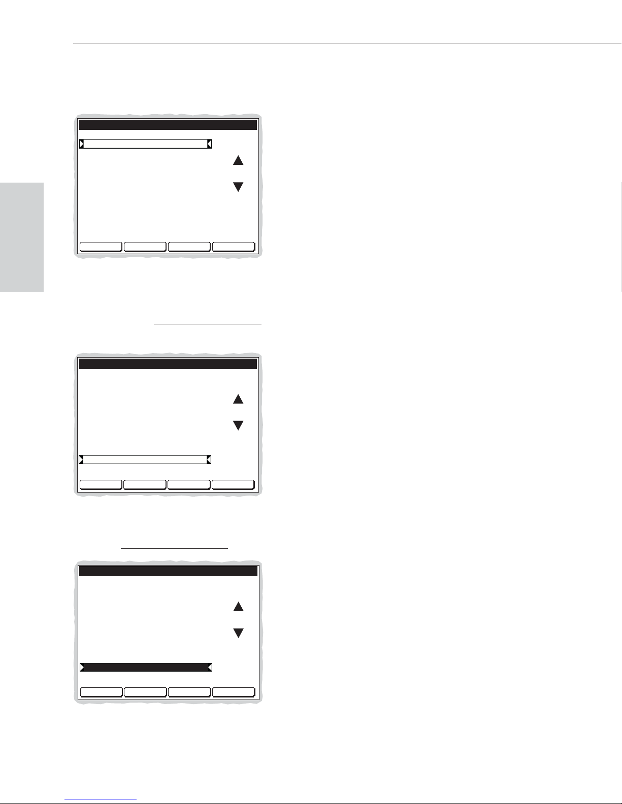
Executing Switches
4. Press the Select key.
The Change Input screen appears, displaying the available input options.
CHANGE INPUT:__ Output:15 VM:0
1 : Reception Mic
2 : Reception Cam
3 : Reception DVD
4 : Mic #1 Control Rm
5 : Mic #2 Control Rm
6 : Mic #3 Control Rm
7 : VCR #1 Control Rm
8 : VCR #2 Control Rm
9 : VCR #3 Control Rm
10 : DVD #1 Control Rm
11 : DVD #2 Control Rm
Back
Select
Executing Switches
Note: If an input is already routed to the selected output, it is highlighted on
the Change Input screen.
5. Locate Input
10: DVD #1 Control Rm by scrolling through the list using
the arrow keys.
CHANGE INPUT:__ Output:15 VM:0
1 : Reception Mic
2 : Reception Cam
3 : Reception DVD
4 : Mic #1 Control Rm
5 : Mic #2 Control Rm
6 : Mic #3 Control Rm
7 : VCR #1 Control Rm
8 : VCR #2 Control Rm
9 : VCR #3 Control Rm
10 : DVD #1 Control Rm
11 : DVD #2 Control Rm
Back
Select
6. Press the Select key.
Input
10: DVD #1 Control Rm is highlighted.
CHANGE INPUT:__ Output:15 VM:0
1 : Reception Mic
2 : Reception Cam
3 : Reception DVD
4 : Mic #1 Control Rm
5 : Mic #2 Control Rm
6 : Mic #3 Control Rm
7 : VCR #1 Control Rm
8 : VCR #2 Control Rm
9 : VCR #3 Control Rm
10 : DVD #1 Control Rm
11 : DVD #2 Control Rm
Back
Select
2-6 CP-20A Control Panel Operation
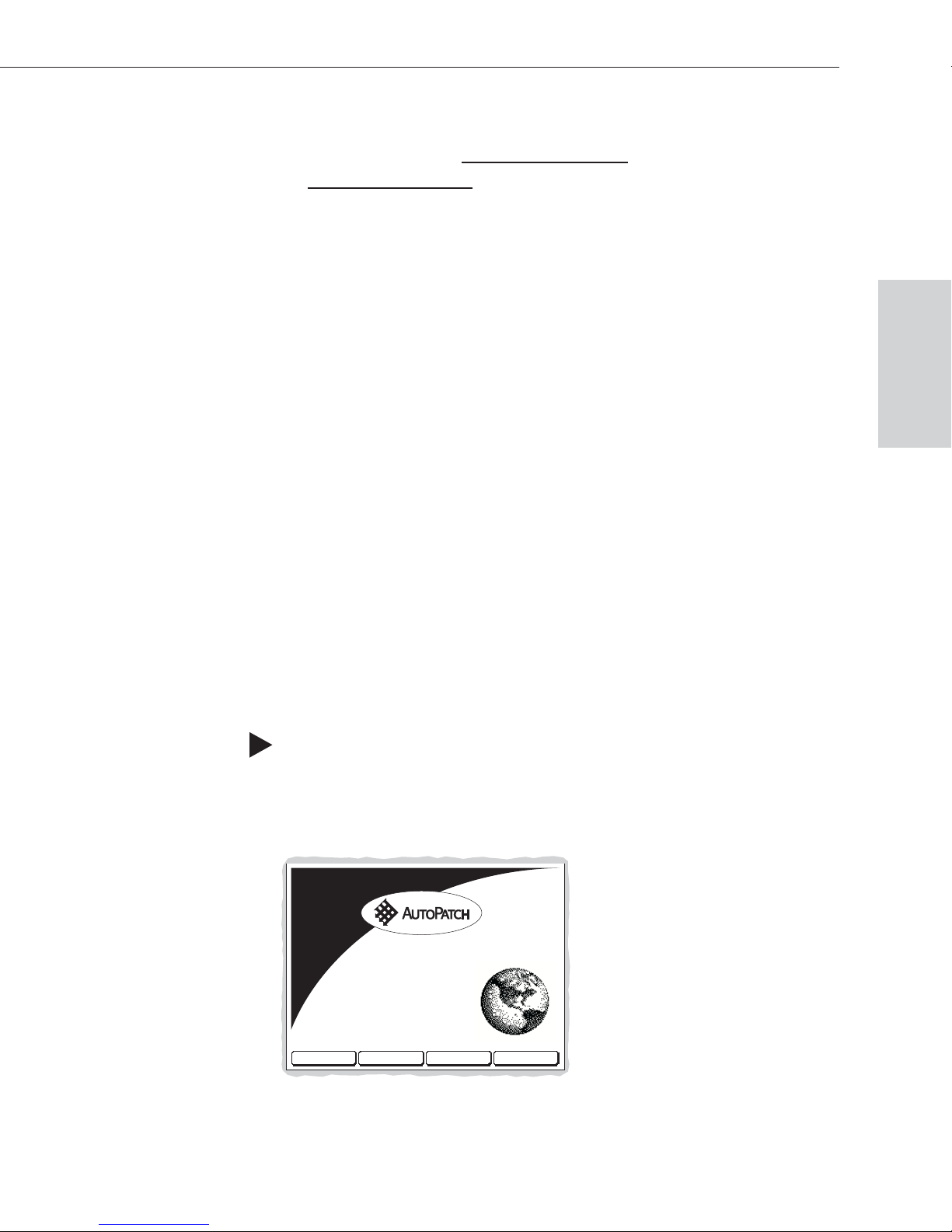
Changing the Virtual Matrix
7. Press the Take key to execute the operation.
The switch to Output
10: DVD #1 Control Rm occurs as soon as the Take key is pressed.
15: Main Monitor Rm B from Input
The system returns to the Change Output screen.
8. Make additional switches.
Or press the Function key to return to the Main Menu screen.
Changing the Virtual Matrix
Virtual matrices are defined in XNConnect and stored in the system’s
N
configuration file (see the X
matrix that contains all signals, so that any input can be routed to any or all
outputs. The same system may have other VMs that switch only audio signals or
only video signals.
Occasionally you may need to execute switches (or other operations) on a virtual
matrix other than the current virtual matrix. Changing the virtual matrix does not
change the default virtual matrix. The system will revert to switching on the
default virtual matrix when the power is cycled.
Connect Help file). Systems usually have a virtual
Executing Switches
The example below gives the steps for changing from routing signals on the
“Audio follow Video,” virtual matrix, to routing on the “Audio, Stereo” virtual
matrix that switches only audio signals. Although this example accesses the VM
(Virtual Matrix) option from the Change menu, this option can be selected from
most of the command menus found along the bottom of the screen.
To change the virtual matrix:
1. At the Main Menu screen, choose the Change command.
If the Change command is not available, press the Function key to view
additional Main Menu options.
High Performance
Signal Routing
CHANGE STATUS DISC AUDIO
CP-20A Control Panel Operation 2-7

Executing Switches
Executing Switches
The Change Input screen appears.
CHANGE INPUT:__ VM:0
1 : Reception Mic
2 : Reception Cam
3 : Reception DVD
4 : Mic #1 Control Rm
5 : Mic #2 Control Rm
6 : Mic #3 Control Rm
7 : VCR #1 Control Rm
8 : VCR #2 Control Rm
9 : VCR #3 Control Rm
10 : DVD #1 Control Rm
11 : DVD #2 Control Rm
V M OutputInput
Back
Select
2. Choose the VM command from the bottom of the screen.
The Virtual Matrix screen appears with the current VM highlighted.
VIRTUAL MATRIX:__
VM0 : Audio follow Video
VM1 : Video
VM2 : Audio, Stereo
Back
Select
3. Locate
VM2: Audio, Stereo by scrolling through the list using the arrow
keys.
VIRTUAL MATRIX:__
VM0 : Audio follow Video
VM1 : Video
VM2 : Audio, Stereo
Back
Select
4. Press the Select key to enter the selection and return to the previous screen.
The system will execute all operations on
VM2: Audio, Stereo until another
VM is selected or the power is cycled.
2-8 CP-20A Control Panel Operation

Disconnecting Switches
Disconnecting a switch deactivates the connection between an input (source)
signal and one or more output (destination) devices. Disconnecting an input
disconnects all outputs receiving that source signal. You can disconnect a switch
by selecting either inputs or outputs from the CP-20A Control Panel.
You can return to the Main Menu screen at any time by pressing the Function
key.
If you need to change the virtual matrix, see “Changing the Virtual Matrix” on
page 2-7.
Note: You can select multiple inputs or outputs by scrolling through the list and
pressing the Select key. The Select key functions as a toggle switch, selecting
and unselecting inputs or outputs in the list each time it is pressed. The Take key
must be pressed for the disconnect operation to execute.
Disconnecting
Switches
CP-20A Control Panel Operation 3-1

Disconnecting Switches
Disconnecting an Input
The example below disconnects Input 27: Audience Mic Mtg Rm A, on Virtual
Matrix 0 from all outputs it is routed to.
To disconnect an input:
Caution: Disconnecting an input disconnects all outputs receiving that source
signal even if a specific output(s) is selected at the same time.
1. At the Main Menu screen, choose the Disc (Disconnect) command.
If the Disc command is not available, press the Function key to view
additional Main Menu options.
Switches
Disconnecting
High Performance
Signal Routing
CHANGE STATUS DISC AUDIO
The Disconnect Input screen appears, displaying the available input options.
DISCONNECT INPUT:__ VM:0
1 : Reception Mic
2 : Reception Cam
3 : Reception DVD
4 : Mic #1 Control Rm
5 : Mic #2 Control Rm
6 : Mic #3 Control Rm
7 : VCR #1 Control Rm
8 : VCR #2 Control Rm
9 : VCR #3 Control Rm
10 : DVD #1 Control Rm
11 : DVD #2 Control Rm
V M
Input
Output
Back
Select
3-2 CP-20A Control Panel Operation

Disconnecting an Input
2. Locate Input 27: Audience Mic Mtg Rm A by scrolling through the list
using the arrow keys. (Press and hold an arrow key to scroll quickly.)
DISCONNECT INPUT:__ VM:0
23 : Podium Cam Mtg Rm A
24 : Audience Cam Mtg Rm A
25 : Tape Deck Mtg Rm A
26 : Main Mic Mtg Rm A
Audience Mic Mtg Rm A
27 :
28 : Podium Cam Mtg Rm B
29 : Audience Cam Mtg Rm B
30 : Tape Deck Mtg Rm B
31 : Main Mic Mtg Rm B
Audience Mic Mtg Rm B
32 :
33 : Satellite Dish
V M
Input
Output
Back
Select
3. Press the Select key.
Input
27: Audience Mic Mtg Rm A is highlighted.
(Additional disconnects can be selected at this time.)
DISCONNECT INPUT:__ VM:0
23 : Podium Cam Mtg Rm A
24 : Audience Cam Mtg Rm A
25 : Tape Deck Mtg Rm A
26 : Main Mic Mtg Rm A
27 :
Audience Mic Mtg Rm A
28 : Podium Cam Mtg Rm B
29 : Audience Cam Mtg Rm B
30 : Tape Deck Mtg Rm B
31 : Main Mic Mtg Rm B
Audience Mic Mtg Rm B
32 :
33 : Satellite Dish
V M
Input
Output
Back
Select
Disconnecting
Switches
4. Press the Take key.
Input
27: Audience Mic Mtg Rm A and all outputs connected to it are
disconnected as soon as the Take key is pressed.
The system returns to the Disconnect Input screen.
5. Press the Function key to return the Main Menu screen.
CP-20A Control Panel Operation 3-3
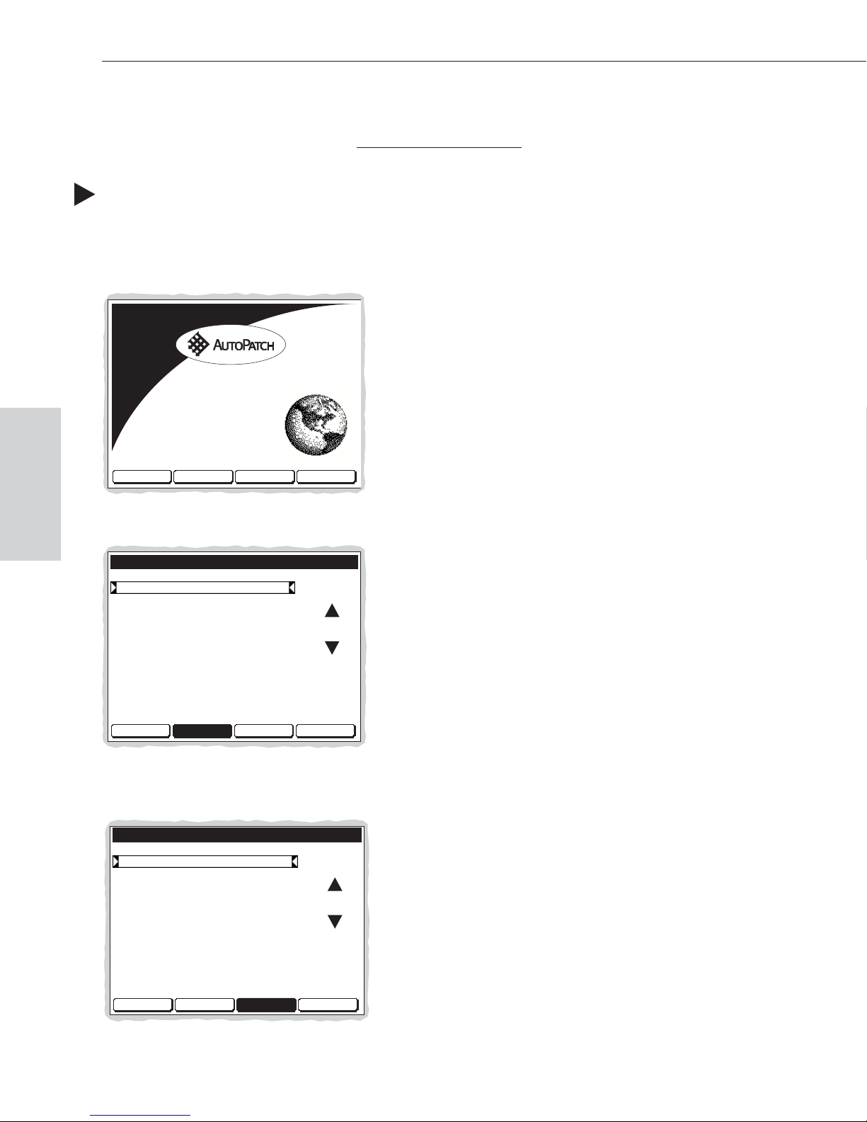
Disconnecting Switches
Disconnecting an Output
The example below disconnects Output 22: Aux Monitor Exec Rm on Virtual
Matrix 0 from its input
To disconnect an output:
1. At the Main Menu screen, choose the Disc (Disconnect) command.
If the Disc command is not available, press the Function key to view
additional Main Menu options.
High Performance
Signal Routing
.
Switches
Disconnecting
CHANGE STATUS DISC AUDIO
The Disconnect Input screen appears.
DISCONNECT INPUT:__ VM:0
1 : Reception Mic
2 : Reception Cam
3 : Reception DVD
4 : Mic #1 Control Rm
5 : Mic #2 Control Rm
6 : Mic #3 Control Rm
7 : VCR #1 Control Rm
8 : VCR #2 Control Rm
9 : VCR #3 Control Rm
10 : DVD #1 Control Rm
11 : DVD #2 Control Rm
V M
Input
Output
Back
Select
2. Choose the Output command from the bottom of the screen.
The Disconnect Output screen appears, displaying the available outputs.
DISCONNECT OUTPUT:__ VM:0
1 : Main Control Monitor
2 : Codec Control Rm
3 : Monitor 1 Control Rm
4 : Monitor 2 Control Rm
5 : Monitor 3 Control Rm
6 : Reception Monitor
7 : Reception Speakers
8 : Lobby Monitor
9 : Main Monitor Rm A
10 : Audience Monitor Rm A
11 : Podium Monitor Rm A
V M
Input Output
Back
Select
3-4 CP-20A Control Panel Operation

Disconnecting an Output
3. Locate Output 22: Aux Monitor Exec Rm by scrolling through the list using
the arrow keys. (Press and hold an arrow key to scroll quickly.)
DISCONNECT OUTPUT:__ VM:0
12 : Main Projector Rm A
13 : Speaker Set 1 Rm A
14 : Speaker Set 2 Rm A
15 : Main Monitor Rm B
16 : Audience Monitor Rm B
17 : Podium Monitor Rm B
18 : Main Projector Rm B
19 : Speaker Set 1 Rm B
20 : Speaker Set 2 Rm B
21 : Main Monitor Exec Rm
22 : Aux Monitor Exec Rm
V M
Input Output
Back
Select
4. Press the Select key.
Output
22: Aux Monitor Exec Rm is highlighted.
(Additional disconnects can be selected at this time.)
DISCONNECT OUTPUT:__ VM:0
12 : Main Projector Rm A
13 : Speaker Set 1 Rm A
14 : Speaker Set 2 Rm A
15 : Main Monitor Rm B
16 : Audience Monitor Rm B
17 : Podium Monitor Rm B
18 : Main Projector Rm B
19 : Speaker Set 1 Rm B
20 : Speaker Set 2 Rm B
21 : Main Monitor Exec Rm
22 : Aux Monitor Exec Rm
V M
Input Output
Back
Select
Disconnecting
Switches
5. Press the Take key.
Output
22: Aux Monitor Exec Rm is disconnected from its input as soon as
the Take key is pressed.
The system returns to the Disconnect Output screen.
6. Press the Function key to return the Main Menu screen.
CP-20A Control Panel Operation 3-5

Verifying Signal Status
Signal status can be verified to confirm that a switch has executed properly or to
confirm correct routing to multiple outputs. Input status and output status both
function on the CP-20A Control Panel. An output can only be connected to one
input; therefore, verifying the status of an output will display only the one input
it is currently connected to.
You can return to the Main Menu screen at any time by pressing the Function
key.
If you need to change the virtual matrix, see “Changing the Virtual Matrix” on
page 2-7.
Verifying Input Status
The example below verifies the signal status for Input 31: Main Mic Mtg Rm B
on Virtual Matrix 0.
Note: If you choose to check the status of an input, all the outputs that are
connected to it will be listed.
To verify the signal status of an input:
1. At the Main Menu screen, choose the Status command.
If the Status command is not available, press the Function key to view
additional Main Menu options.
High Performance
Signal Routing
Signal Status
Verifying
CHANGE STATUS DISC AUDIO
CP-20A Control Panel Operation 4-1

Verifying Signal Status
The Status Input screen appears, displaying the available inputs.
STATUS INPUT:__ VM:0
1 : Reception Mic
2 : Reception Cam
3 : Reception DVD
4 : Mic #1 Control Rm
5 : Mic #2 Control Rm
6 : Mic #3 Control Rm
7 : VCR #1 Control Rm
8 : VCR #2 Control Rm
9 : VCR #3 Control Rm
10 : DVD #1 Control Rm
11 : DVD #2 Control Rm
V M
Input
Output
Back
Select
Verifying
Signal Status
2. Locate Input
31: Main Mic Mtg Rm B by scrolling through the list using the
arrow keys. (Press and hold an arrow key to scroll quickly.)
STATUS INPUT:__ VM:0
23 : Podium Cam Mtg Rm A
24 : Audience Cam Mtg Rm A
25 : Tape Deck Mtg Rm A
26 : Main Mic Mtg Rm A
Audience Mic Mtg Rm A
27 :
28 : Podium Cam Mtg Rm B
29 : Audience Cam Mtg Rm B
30 : Tape Deck Mtg Rm B
31 : Main Mic Mtg Rm B
Audience Mic Mtg Rm B
32 :
33 : Satellite Dish
V M
Input
Output
Back
Select
3. Press the Select key to enter the selection.
The Status Results screen appears listing the outputs,
13: Speaker Set 1 Rm A, 14: Speaker Set 2 Rm A,
19: Speaker Set 1 Rm B
to the input being verified.
, and 20: Speaker Set 2 Rm B, that are connected
STATUS RESULTS: Input:31 VM:0
13 : Speaker Set 1 Rm A
14 : Speaker Set 2 Rm A
19 : Speaker Set 1 Rm B
20 : Speaker Set 2 Rm B
Note: If the screen is full, more outputs than the ones displayed may be active.
Use the arrow keys to scroll to check for additional active outputs.
4-2 CP-20A Control Panel Operation
Back

Verifying Output Status
4. Press the Back key to return to the Status Input screen to verify the status of
additional signals.
Or press the Function key to return to the Main Menu screen.
Verifying Output Status
The example below verifies the signal status for Output 20: Speaker Set 2 Rm B
on Virtual Matrix 0.
Note: Checking the status of an output will not show other outputs connected to
same input.
To verify the signal status of an output:
1. At the Main Menu screen, choose the Status command.
If the Status command is not available, press the Function key to view
additional Main Menu options.
High Performance
Signal Routing
CHANGE STATUS DISC AUDIO
The Status Input screen appears.
STATUS INPUT:__ VM:0
1 : Reception Mic
2 : Reception Cam
3 : Reception DVD
4 : Mic #1 Control Rm
5 : Mic #2 Control Rm
6 : Mic #3 Control Rm
7 : VCR #1 Control Rm
8 : VCR #2 Control Rm
9 : VCR #3 Control Rm
10 : DVD #1 Control Rm
11 : DVD #2 Control Rm
V M
Input
Output
Signal Status
Verifying
Back
Select
CP-20A Control Panel Operation 4-3

Verifying Signal Status
2. Choose the Output command from the bottom of the screen.
The Status Output screen appears, displaying the available output options.
STATUS OUTPUT:__ VM:0
1 : Main Control Monitor
2 : Codec Control Rm
3 : Monitor 1 Control Rm
4 : Monitor 2 Control Rm
5 : Monitor 3 Control Rm
6 : Reception Monitor
7 : Reception Speakers
8 : Lobby Monitor
9 : Main Monitor Rm A
10 : Audience Monitor Rm A
11 : Podium Monitor Rm A
V M
Input Output
Back
Select
Verifying
Signal Status
3. Locate Output
20: Speaker Set 2 Rm B by scrolling through the list using
the arrow keys. (Press and hold an arrow key to scroll quickly.)
STATUS OUTPUT:__ VM:0
12 : Main Projector Rm A
13 : Speaker Set 1 Rm A
14 : Speaker Set 2 Rm A
15 : Main Monitor Rm B
16 : Audience Monitor Rm B
17 : Podium Monitor Rm B
18 : Main Projector Rm B
19 : Speaker Set 1 Rm B
20 : Speaker Set 2 Rm B
21 : Main Monitor Exec Rm
22 : Aux Monitor Exec Rm
V M
Input Output
Back
Select
4. Press the Select key to enter the selection.
The Status Results screen appears, displaying the Input,
31: Main Mic Mtg Rm B, routed to the output being verified.
STATUS RESULTS: Output:20 VM:0
31 : Main Mic Mtg Rm B
Back
5. Press the Back key to return to the Status Output screen to verify the status
of additional signals.
Or press the Function key to return to the Main Menu screen.
4-4 CP-20A Control Panel Operation

Executing Presets
Global and local presets are predefined sets of switches that can be easily executed.
Local Presets
At the time of this publication, local presets cannot be executed using the CP-20A
Control Panel. Local presets are defined in X
file) and can be executed using BCS commands. More information on local presets
and other operations executed with BCS commands can be found in the BCS Serial
Control Protocol section of this binder.
Global Presets
Global presets allow you to replicate an entire system state. The system state
includes all current signal routings (regardless of the number of virtual matrices
involved) and any digital gain and/or volume settings. A global preset number is
assigned to a system state during runtime using the CP-20A Control Panel (or BCS
commands) and stored by the system. That system state can then be restored at any
time by selecting the assigned global preset number.
The CP-20A stores up to 64 global presets and displays 64 numbers. Since the
panel can be used to operate different types of matrix switchers, check the product
documentation for any limitations to the number of supported global presets.
N
Connect (see the XNConnect Help
Executing Presets
Note: We strongly recommend keeping track of the number used and the system’s
routing state for each global preset. If another system state is assigned a previously
used number, the former state will be automatically overwritten.
Global presets cannot be defined (created) in X
Caution: If the system is reconfigured, global presets may be lost, depending on
the method used to load the new configuration file (see the X
The example on page 5-2 defines the current system state as 3: Global Preset 3.
The example on page 5-4 executes
system to the state it was in when the global preset was defined.
N
Connect.
N
Connect Help file).
3: Global Preset 3, which restores the
CP-20A Control Panel Operation 5-1

Executing Presets
Defining Global Presets
To define a global preset:
1. Route the system to the desired state.
2. At the Main Menu screen, choose the Global command.
If the Global command is not available, press the Function key to view
additional Main Menu options.
High Performance
Signal Routing
GLOBAL SETUP
Executing Presets
The Execute Global Preset screen appears.
EXECUTE GLOBAL PRESET:__
1 : Global Preset 1
2 : Global Preset 2
3 : Global Preset 3
4 : Global Preset 4
5 : Global Preset 5
6 : Global Preset 6
7 : Global Preset 7
8 : Global Preset 8
9 : Global Preset 9
10 : Global Preset 10
11 : Global Preset 11
Execute
Define
Back
Select
3. Choose the Define command from the bottom of the screen.
The Define Global Preset screen appears.
A complete list of numbers is displayed, regardless of whether or not a
system state has been assigned to each number.
DEFINE GLOBAL PRESET:__
1 : Global Preset 1
2 : Global Preset 2
3 : Global Preset 3
4 : Global Preset 4
5 : Global Preset 5
6 : Global Preset 6
7 : Global Preset 7
8 : Global Preset 8
9 : Global Preset 9
10 : Global Preset 10
11 : Global Preset 11
Execute
Define
Back
Select
5-2 CP-20A Control Panel Operation
 Loading...