

Autopage RST-1100 Owner's Manual

Jun/22/2009
RST1000 OP REV.A 1
MODEL RST-1100
REMOTE ENGINE STARTER
WITH ALARM SYSTEM
OWNER’S MANUAL
WARNINGS:
As with any product that performs automatic functions, there are certain safety precautions that you must
practice and be aware of.
1. Keep the transmitter out of children’s reach.
2. Do not leave anyone in the vehicle while running on remote control.
3. Alert servicing personnel that the vehicle can be started automatically.
4. Do not start the vehicle by remote while it’s in an enclosed area or garage.
5. Always apply the parking brake and lock the vehicle as you exit the vehicle.
6. The vehicle windows must be rolled up.
7. Should the unit malfunction, disconnect the fuse until the problem is corrected.
8. The use and operations of this system is the sole responsibility of the operator.
9. Some areas may have local ordinances that prohibit leaving a vehicle running on public streets.
10. Do not start the vehicle by remote while the standard transmission vehicle is parked at a steep place.

Jun/22/2009
RST1000 OP REV.A 2
OLED REMOTE TRANSCEIVER:
A. OLED DISPLAY……………………………….………………………………………………………………………… 4
B.
CHARGE THE BATTERY
……….…………………………………………………………………………..…….. 4
C.
MAIN PAGE
…………………………………………………………………………………………………………… 5
D.
SELECT THE TRANSCEIVER’S BUTTON CONFIGURATION
…………………………………………. 6
E.
SELECT THE TRANSCEIVER FEATURES
…………………………………………..………………………. 6
P1-1: Enable / Disable Bi Sound While Pressing Button (7)
P1-2: Button Lock Setting (7)
P1-3: Melody / Vibration Mode (7)
P1-4: Demo Mode (8)
P2-1: Power Save Mode (8)
P2-2: Parking Meter Setting (8)
P2-3: Parking Area Setting (8)
P2-4: “Light For OLED” Timer Setting (9)
P3-1: Timer Setting (9)
P3-2: Alert Alarm Timer Setting (9)
P3-3: Count Down Timer Setting (10)
P3-4: Daily Start Timer Setting (10)
P4-1: Name of
Transceiver
Setting (11)
P5-1: Name of
Channel
Setting (11)
P6-1: Language Setting (11)
P6-4: Set To Defaults (12)
TABLE OF CONTENTS:
A. REMOTE TRANSMITTER OPERATION ……………………………………….………………….………….…… 12
B. LED DISPLAY .……………..……………………………………………………………………….……………..……12
C. CHIRP INDICATOR ..………..……………………………………………………………………………….…..……. 13
D. PARKING LIGHT …….……..…………………………………………………………………………..……….….…. 13
E. ACTIVE ARMING – ARM & LOCK .……………………………………………………………………….…………. 13
Ajar Warning / Silent Arming / Sensor By-Pass / Noiseless Mode / Hidden Alarm Mode / Auto Immobiliser /
Arming While Driving
F. PASSIVE ARMING .…………………………………………..…………………….………………………….….…… 14
Passive Arming with Passive Door Locking / Passive Arming By-Pass
G. ACTIVE DISARMING – UNLOCK & DISARM .…………………………………………………..…………………. 14
Silent Disarming / Tamper Disarming / Pathway Illumination / Two Steps Door Unlock / Automatic Re-Arm
H. DISARMING WITHOUT A TRANSMITTER .……………..…………………………………………………..…….... 14
Overrides the Alarm without Password Pin Code / Overrides the Alarm With Password Pin Code
I. VALET MODE .……………..…………………………………………………………………….…………………..…... 15
J. CAR LOCATOR .……………………………………………………………………….……………………………...… 15
K. PANIC FUNCTION .……………………………………………………………………………..….……………….….. 15
L. TRIGGER THE SYSTEM .………………………………………..………………………..………….………….…….. 15
Stop The Melody Sound / Noise Abatement Circuit
M. ANTI CAR- JACKING .…………………………………………………………………………………………….…….. 16
N. SYSTEM’S TRIGGER CHECK ……………………………………………………………….….….…………....……. 17
O. SYSTEM’S STATUS CHECK ……………………………………………………………..……….……………..……. 17
P. DRIVER PAGING / LOSE AND FOUND ………………………….…………..……………………...………………...17
Q. DOME LIGHT CONVENIENCE DELAY & SUPERVISION ……………………..………………….………..……....17
R. IGNITION CONTROL THE DOOR LOCK/UNLOCK. ………..………………….……………………………..…..….17
S. TRUNK RELEASE (CHANNEL 3) OUTPUT ………..……………………………………………….……………..….17
T. CHANNEL 4 / 5 / 6 / 7 TIMER CONTROL OUTPUT ………..……………………………………………….………..17
U. MULTI-VEHICLE SECURITY OPREATION: ………..……………………………………………………………….…18
V. OUT OF RANGE INDICATION: ………..…………………………….….…………………………………………….…18
W. POWER SAVER MODE: …….…..……………………………………………………………….…….……………….. 18
X. POWER ON MEMONRY: ………..……………………………………………………………….…….……………….. 18
REMOTE START OPERATION:
A. TO REMOTE START THE VEHICLE ………..……………………………………………………………..………….. 19
B. ENGINE START MEMORIZING FOR THE VEHICLE WITH STANDARD TRANSMISSION GEAR …………... 19
C. TO OPERATE THE VEHICLE WHILE RUNNING ON THE REMOTE START ………………………………..….. 19
D. TEMPORARY STOP FEATURE ……………………………………………….………………….…………………… 20
E. TURBO TIMER MODE ……………………..………………………………….……………….………...………..….… 20
F. TIMER START …………………………………………….…………….……………………….…..…………………… 20
3 (2 or 1) Hours Timer Start / Daily Timer Start / Cancel the Timer Start
G. TEMPERATURE CHECK …………….……………………………………………….…...……….…………….….… 20
H. TO TURN OFF THE REMOTE START ……………………………………………….….…….………………….….…20
I. SHUT-DOWN INPUT FOR REMOTE STARTER …………………………….……………………………..….………. 21
J. DISABLING THE REMOTE START SYSTEM …………………………….……………………..……………….….… 21
TEST MODE …………………..…………….……………………………………………….…...……….………..…….…… 21
SHUTDOWN DIAGNOSTICS …………….……………………………………………….…...……….………..…….…… 21
Jun/22/2009
RST1000 OP REV.A 3
Vibration Mode
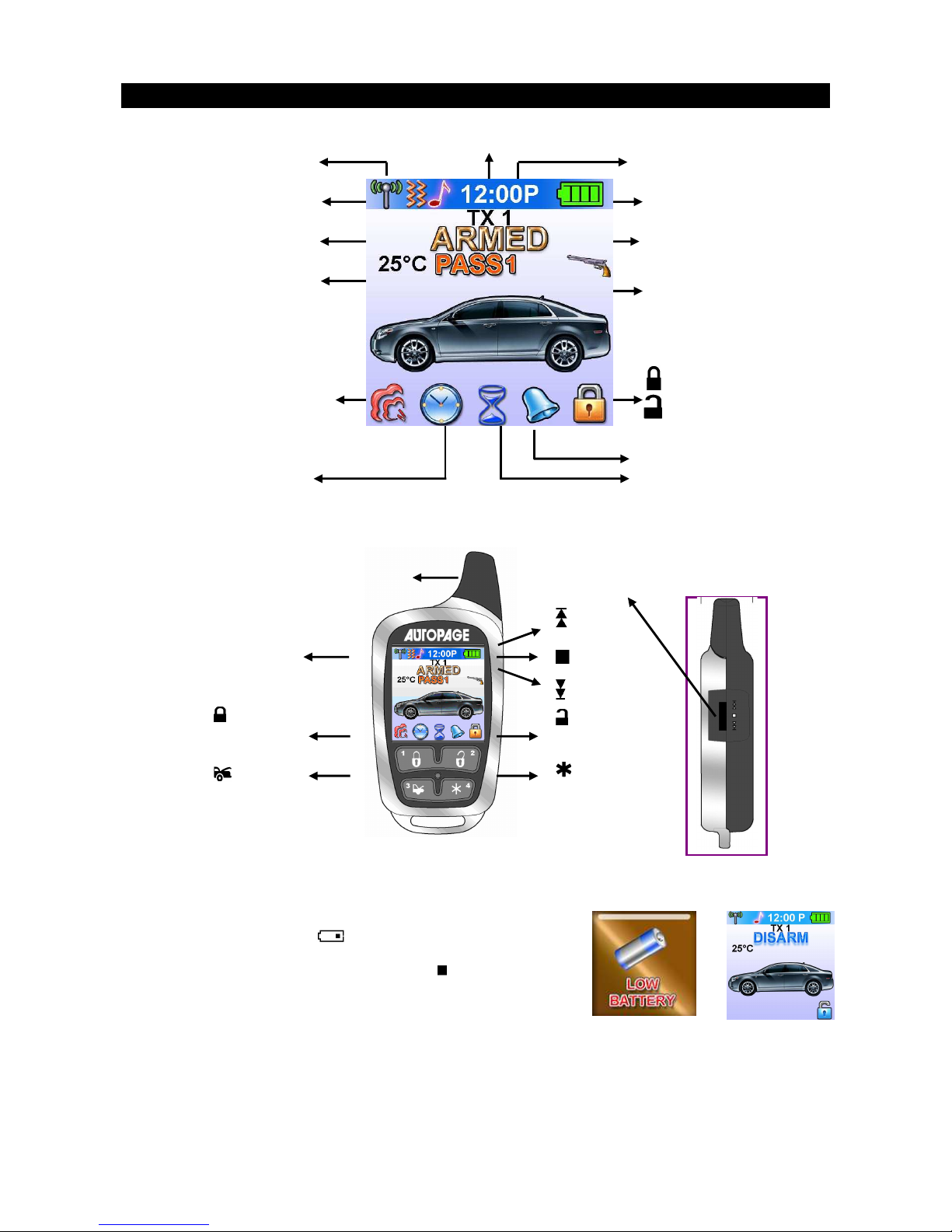
REMOTE TRANSCEIVER (TX)
A. OLED DISPLAY
I n case the remote transceiver malfunction,
errors or freeze of display, it is recommended
to reset your remote transceiver.
B. CHARGE THE BATTERY
Power by built-in 3.7V lithium polymer b
attery, if the OLED screen
display low battery or
is flash, charge your remote
transceiver. While the battery of the Remote Transceiver is under
the battery charging, you can push the ” ”
button to check
charging condition.
switch
Button
Button
1
OLED Display
Name of Transmitter
Button
Button
3
Button
Button
2
Button
Button
4
switch
button
Antenna
Level and
push switch
Battery Level
Car Jacking
In – Range Indicator
Door Lock
Door Unlock
Alarm Status
Temperature
Engine Running
Melody Mode
Timer Start
Alert Alarm
Count Down Timer
Parking Timer
Timer
Bypass Sensor 1
(Zone 4)
Bypass Sensor 2
(Zone 6)
Jun/22/2009
RST1000 OP REV.A 4
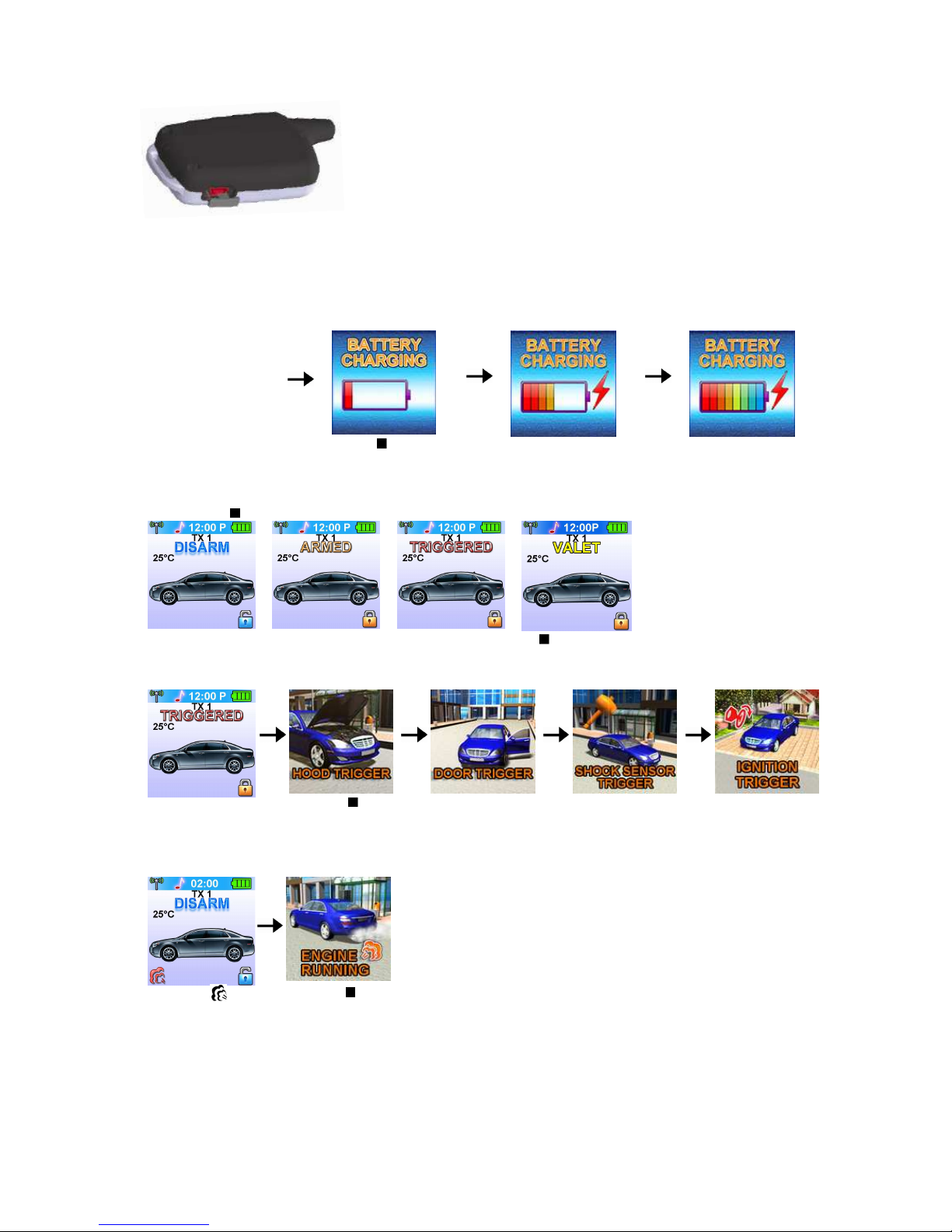
1. The remote transceiver equipped AC ADAPTOR (Output
Voltage: 4.2VDC – 5.5VDC and with same USB plug),
then you can charge the battery indoors.
2. Charging is difficult in places subject to extremely high/
low temperatures.
3. To protect the battery, it is recommended to temperature
charge in places with temperature of 5 C to 35 C (41 F to
95 F).
While the battery of
the Remote
Transceiver is under
charging.
Push the button; the
screen will display
Battery charging.
C. MAIN PAGE:
1. Press the button, the screen will display main page.
2. While the icon flashing on the OLED screen, press the button, the OLED screen will display the
detail of the flash icon, the display sequence of flash icon as follows: TRIGGERED / ENGINE
RUNNING / COUNT DOWN TIMER / TIMER START / ALART TIMER condition.
While the
TRIGGERED icon
flash.
Push the
button to display
triggered area.
While the
icon flash
Push the button
Charge Input
USB Input
Jun/22/2009
RST1000 OP REV.A 5
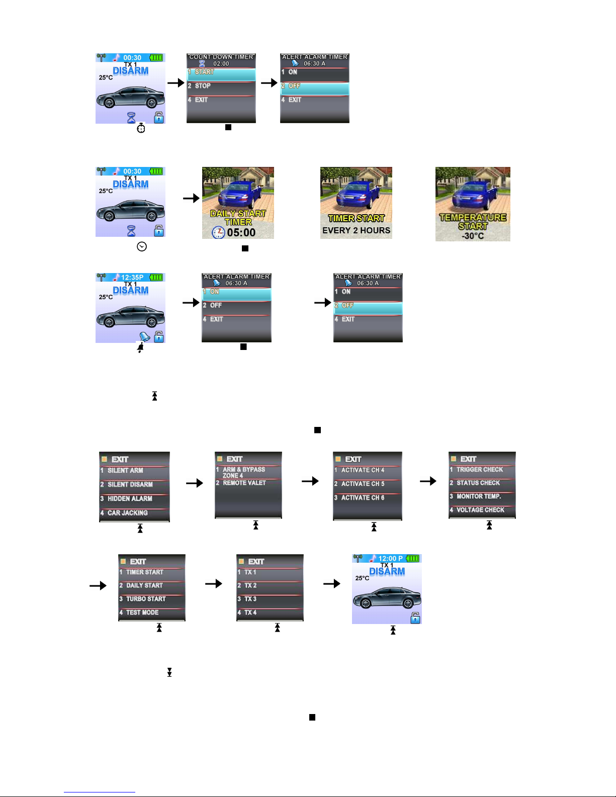
While the
icon
flash
Push the
button, the count
down timer will
display.
Press the button
2 to set off the
count down time
or
or
While the icon flash
Push the button, the OLED screen will display individually i.e. daily start timer
,
timer start or temperature start, depend on which you selected.
While the icon
flash
Push the button, the alert
alarm time will display.
Press the button 2 to set off
the alert alarm timer
D. SELECT THE TRANSCEIVER’S BUTTON CONFIGURATION:
1. Spin up the Switch to select the transceiver button configuration you need and the OLED screen will
display the transceiver button configuration you select.
2. Within 5 seconds press the button 1, 2, 3 or 4 to remote control “button configuration” you selected.
Note: If 5 seconds of inactivity expired, or push the button, the transceiver button configuration mode
will exit.
Spin up the switch
to the page 1
Spin up the switch
to the page 2
Spin up the switch
to the page 3
Spin up the switch
to the page 4
Spin up the switch
to the page 5
Spin up the switch
to the page 6
Spin up the switch
resume to main page.
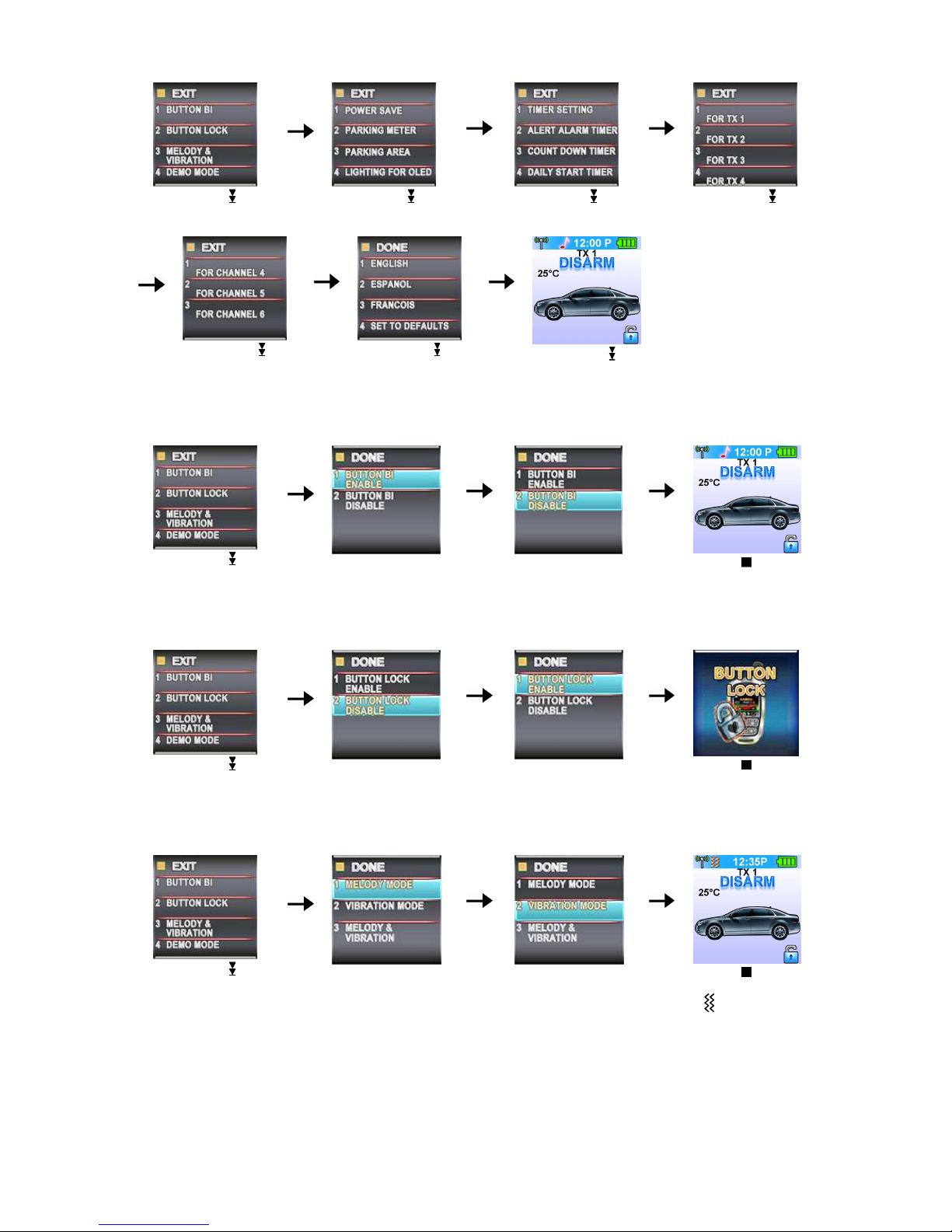
E. SELECT THE TRANSCEIVER FEATURES:
1. Spin down the Switch to select the transceiver feature you need and the OLED screen will display
the features you select.
2. Press the button 1, 2, 3 or 4 once within 3 seconds after finished selection and the OLED screen will
change the display alternatively.
Note: If 5 seconds of inactivity expire, or push the
button, the transceiver features program mode will
exit.
Jun/22/2009
RST1000 OP REV.A 6
Spin down the switch
to the page 1
Spin down the switch
to the page 2
Spin down the switch
to the page 3
Spin down the switch
to the page 4
Spin down the
switch
to the page 5
Spin down the
switch
to the page 6
Spin down the
switch
resume to main page.
E- P1- 1. “BUTTON BI” SETTING: Example: Set the “Button Bi Disable”.
It has a short “bi” sound while pressing the button of the remote transceiver
Spin down the switch
to the page 1
Press the button 1 and it
will display previously
setting
Press the button 2 to
change the setting
Press the button and
the setting is done.
E- P1- 2. “BUTTON LOCK” SETTING: Example: Set the “Button Lock Enable”.
Spin down the switch
to the page 1
Press the button 2 and it
will display previously
setting
Press the button 1 to
change the setting
Press the button and
the setting is done.
D- P1- 3. “MELODY / VIBRATION MODE” SETTING: Example: set the Vibration mode.
Spin down the switch
to the page 1
Press the button 3 and it
will display previously
setting
Press the button 2 to
change the setting
Press the button and
the setting is done also
the icon will display
on the OLED screen
E- P1- 4. “DEMO MODE”:
 Loading...