

Page 1
DR W 1711 87A B
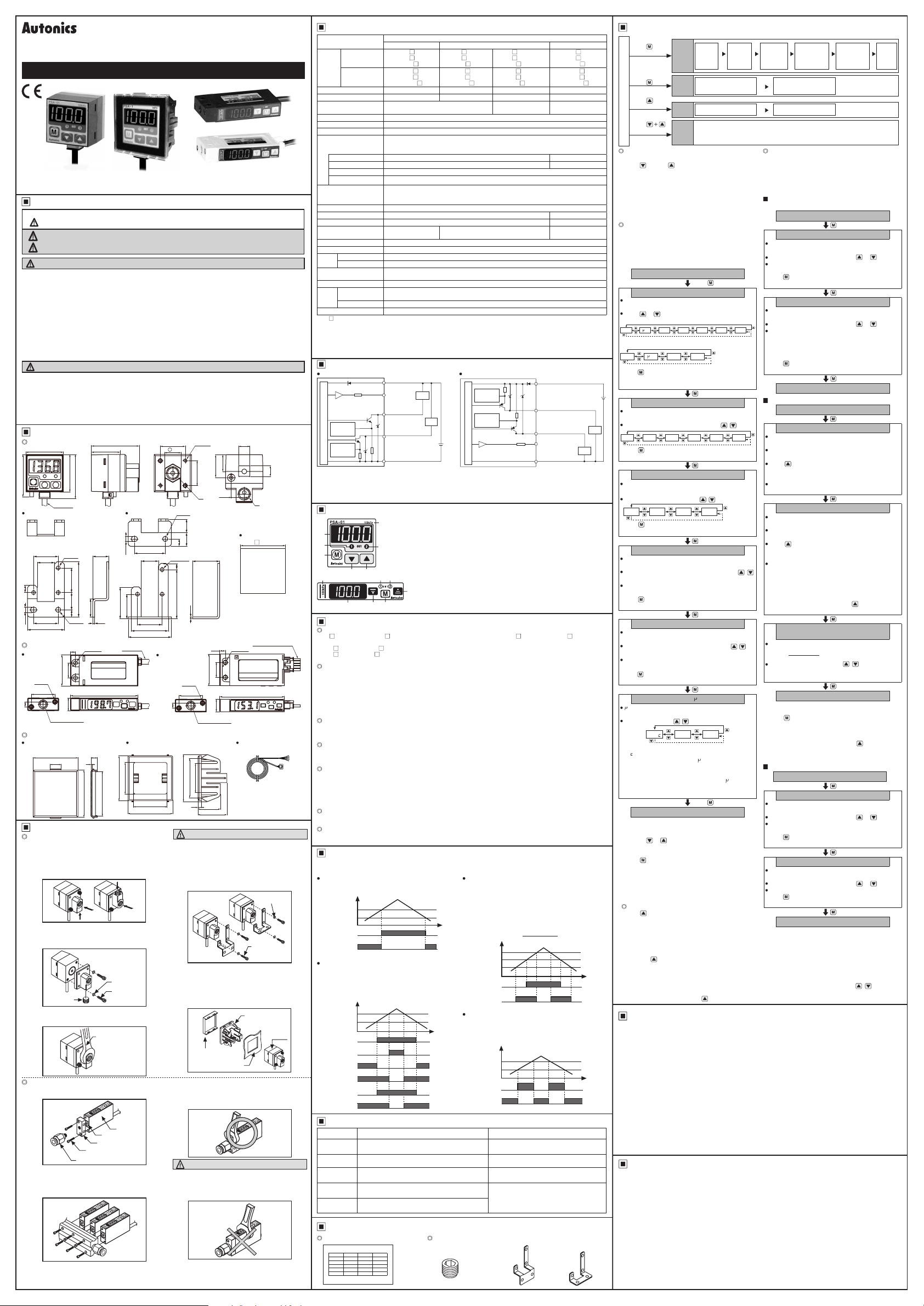
DIGITAL PRESSURE SENSOR
PSA/PSB SERIES
I N S T R U C T I O N M A N U A L
PSA PSB
(cable type)
(connector type)
Please read the following safety considerations before use.
Safety Considerations
Please observe all safety considerations for safe and proper product operation to avoid hazards.
※
symbol represents caution due to special circumstances in which hazards may occur.
※
Warning
Caution
Warning
1. Fail-safe device must be installed when using the unit with machinery that may cause serious injury or
substantial economic loss. (e.g. nuclear power control, medical equipment, ships, vehicles, railways,
aircraft, combustion apparatus, safety equipment, crime/disaster prevention devices, etc.)
Failure to follow this instruction may result in personal injury, economic loss or re.
2. Do not use the unit in the place where ammable/explosive/corrosive gas, high humidity, direct sunlight,
radiant heat, vibration, impact, or salinity may be present.
Failure to follow this instruction may result in explosion or re.
3. Install on a device panel or to a pressure port directrly to use.
Failure to follow this instruction may result in re.
4. Do not connect, repair, or inspect the unit while connected to a power source.
Failure to follow this instruction may result in re.
5. Check 'Connections' before wiring.
Failure to follow this instruction may result in re.
6. Do not disassemble or modify the unit.
Failure to follow this instruction may result in re.
Caution
1. Use the unit within the rated specications.
Failure to follow this instruction may result in re or product damage.
2. Use dry cloth to clean the unit, and do not use water or organic solvent.
Failure to follow this instruction may result in re.
3. This product is designed to detect the pressure of noncorrosive gas. Do not use for corrosive gas.
Failure to follow this instruction may result in product damage.
4. Keep metal chip, dust, and wire residue from owing into the unit.
Failure to follow this instruction may result in re or product damage.
Dimensions
PSA Series
30
34
Bracket A Bracket B
20
14
6
20
4.2
30
PSB Series
Cable type
2-M2
19
4
Sold separately
Front cover
(PSA, PSO-P01)
Installation
PSA Series
1. When installing pressure port it is able to bring
pressure from 3 directions by changing the
mounting direction of the pressure port.
2. Standard pressure port is Rc1/8 and option
pressure port is NPT1/8. Use a general one-
touch tting.
3. Please use seal tape at port plug in order to
prevent pressure leak.
4. Please block another two pressure ports not
used with port plug.
Port plug
5. Please connect it by using spanner(13mm) at the
metal part in order not to overload on the body
when connecting one touch tting.
PSB Series
1. Pressure port is M5.
t is able to use general one touch tting.
2. It is able to use it without the pressure port
according to environment.
In this case O-Ring between pressure port
and its body should not be taken out in
order to prevent pressure leak.
※
Do not pull the cable with a tensile strength of 30N or over.
※
The above specications are subject to change and some models may be discontinued without notice.
※
Be sure to follow cautions written in the instruction manual and the technical descriptions
(catalog, homepage).
Thank you for choosing our Autonics product.
Failure to follow these instructions may result in serious injury or death.
Failure to follow these instructions may result in personal injury or product damage.
20
13
3-Ø3.2
5
40
2-M3
20
A
Ø4.2
1111
6
22
1.6
25 5
9
13.4
18.4
10.5
※
A: Rc1/8 (standard), NPT1/8 (option)
Panel cut-out
( panel thickness:
0.8 to 3.5mm)
4 5
2-Ø3 2
12
2-M2
19
4
423526
The tightening torque of one touch tting
should be Max. 10N.m.
It may cause mechanical trouble.
6. PSA Series has 2 kinds of brackets so it is able
to install it in two dierent ways.
7. At rst, please unscrew hexagon wrench bolt and
assemble the bracket on this unit by xing the
hexagon wrench bolt.
In this case, tightening torque of hexagon
wrench should be max. 3N.m.
It may cause mechanical trouble.
8. Front cover (PSO-P01) and mounting bracket
(PSO-01) are sold separately.
Please refer to the below pictures for
installation.
3. Please connect it by using spanner(10mm)
at pressure port in order not to overload on
the body when connecting one touch tting.
The tightening torque of one touch tting and
hexagon wrench should be Max. 5N m and
2N m. It may cause mechanical trouble.
Please do not use spanner to install as it may
cause mechanical trouble.
Pressure port
M5
3
Caution
Front
cover
(PSO-P01)
Caution
10
Tap depth: 5
20
25.8
Connector cable
(PSB, PSO-C01)
※
Ø4mm, 5-wire, 2m
(AWG24, core diameter:
0.08mm, number of
cores: 40, insulator
diameter: Ø1mm)
Mounting bracket
(PSO-01)
Bracket
panel
30
Ø4, 2m
3-Ø3.2
20
14
6
Ø4.2
4
25
12
10 3
Pressure port
M5
Tap depth: 5
40
9.7
35.5
13
45
15
1.6
2-Ø3.4
54.2
5.7
1
42
13mm Spanner
Pressure port
Hexagon wrench bolt
(M2X10)
One touch tting
23
40
O-Ring
38.5
40
Spring washer
Hexagon
wrench bolt
Body
25
4.2
14
26
20
20
30
35
Ø4, 2m
Mounting bracket
(PSA, PSO-01)
28.2
30
40
Connector type
(unit: mm)
8.5
A
0 5
36
0
Connector cable 3m
(Accessory)
52
Spring
washer
Hexagon
wrench bolt
Body
(PSA)
10mm spanner
Specifications
Pressure type
NPN open
collector output
※
1
Model
PNP open
collector output
Rated pressure range 0.0 to -101.3kPa 0.0 to 100.0kPa 0 to 1,000kPa -100.0 to 100.0kPa
Display pressure range 5.0 to -101.3kPa -5.0 to 110.0kPa -50 to 1,100kPa -101.2 to 110.0kPa
Max. pressure range 2 times of rated pressure
Applicable uid Air, Non-corrosive gas
Power supply 12-24VDC ±10%(Ripple P-P: max. 10%)
Current consumption Max. 50mA
Control output
Hysteresis
Repeat error ±0.2% F.S. ±1digit ±0.2% F.S.±2digits
Response time Selectable 2.5ms, 5ms, 100ms, 500ms
Short circuit protection
Analog output
Display digit 3½ digit LED
Display method 7 Segment LED
Min. display interval 1digit(psi unit: 2 digits are xed) 2digits
Pressure unit
Display accuracy 0 to 50℃: Max. ±1% F.S., -10 to 0℃: Max. ±2% F.S.
Vibration 1.5mm amplitude at frequency of 10 to 55Hz in each of X, Y, Z directions for 2 hours
Ambient temperature
Environ
-ment
Ambient humidity 35 to 85%RH, Storage: 35 to 85%RH
Material
Protection IP40(IEC standard)
Cable type
Cable
Connector type 5-wire, Length: 3m(AWG 24, insulation diameter: Ø1.4mm)
3
※
Weight
※
' is pressure port type. PSA standard: Rc1/8, PSA option: NPT1/8, PSB standard: M5.
1: '
※
2: In hysteresis output mode, detection dierence is variable.
※
3: The weight is with packaging and the weight in parentheses is only unit weight.
※
F.S.: Rated pressure.
※
The specication of pressure port for PSA Series is marked on the upper part of the case.
※ForusingmmH2Ounit,multiplydisplayvalueby100.
※
Environment resistance is rated at no freezing or condensation.
Input/Output Circuit and Connection Diagram
NPN open collector output type PNP open collector output type
1kΩ
Over current
protection
circuit
Main circuit
Over current
protection
circuit
※
There is no over current protection circuit in analog voltage output type.
Do not connect this unit to power source or capacitive load directly.
※
Please observe input impedance of connected equipment when using analog voltage output.
And be sure with voltage drop by resistance of extended wire.
※
If short-circuit the control output terminal or supply current over the rated specification, control signal is abnormal
due to the current protection circuit
Unit Descriptions
1
2
4
6 5
7
1
Functions
Pressure unit change
PS -V01(C)(P) and PS -C01(C)(P) has 7 kinds of pressure unit and PS -01(C)(P) and PS -1(C)(P)
has 4 kinds of pressure unit. Please select the proper unit for application.
• PS -V01(C)(P), PS -C01(C)(P) : kPa, kgf/cm², bar, psi, mmHg, inHg, mmH2O
• PS -01(C)(P), PS -1(C)(P) : kPa, kgf/cm², bar, psi
※
When using mmH2O unit, multiply display value by 100.
Output mode change
There are 6 kinds of control output mode in order to provide the various detection.
Select a mode for your proper application.
• Hysteresis mode[
• Automatic sensitivity setting mode[
proper position.
• Independent 2 output mode[
with one product.
• Window comparison output mode[
Response time change (chattering prevention)
It can prevent chattering of control output by changing response time. t is able to set 4 kinds of
response time (2.5, 5, 100, 500ms) and if the response time is getting longer, the sensing will be more
stable by increasing the number of digital lter.
Analog output scale setting
It is not xed the analog output(1-5VDC) scale as the rated pressure range but this is a function to
change properly for user's application. When the position [
for 5VDC output are set, the pressure range of
Key lock
This unit has 2 kinds of key lock function in order to prevent wrong operation.
•
: All keys are locked, it is impossible to change any parameter setting/preset, zero point
LOC
adjustment, peak hold and bottom hold. (enables to change
•
: t is impossible to change parameter setting/preset, zero point adjustment. (Enables to check
PA.L
peak hold and bottom hold, and to change
•
: All of the setting is available, all keys are unlocked.
UNL
Zero point adjustment
This function is to set the display value of pressure at zero when port is opened to atmospheric pressure.
Zero point adjustment aects analog output voltage.
Peak hold and bottom hold function
This function is to diagnosis malfunction of the system caused by parasitic pressure or to check through
memorizing the max /min. pressure that occurred in the system.
Output Operation Mode
※
PSA/PSB Series has 6 kinds of output operation mode, please use proper output operation mode
in accordance with sensing.
Hysteresis mode[
It can be set for pressure sensing level [
sensing dierences [
Pressure
ST1
ST2
ON
OUT1
OFF
ON
OUT2
OFF
Independent 2 output mode[
and
①
ST1
ST2
display pressure range. One is for control, the
other is for alarm or optional control.
②Thesensing
(2 digits for psi unit and compound type)
Pressure
ST2
ST1
ON
OUT1
OFF
F 3
ON
OUT2
OFF
ON
OUT1
OFF
F 4
ON
OUT2
OFF
ON
OUT1
OFF
F 5
ON
OUT2
OFF
Gauge pressure
Negative pressure type
PSA-V01PSB-V01PSB-V01CPSA-V01PPSB-V01PPSB-V01CP-
NPN or PNP open collector output
• Load voltage: Max. 30VDC • Load current: Max. 100mA
• Residual voltage -NPN: Max. 1VDC , PNP: Max. 2VDC
※
2
1digit xed(2digits for psi unit) 2digits xed
Built-in
• Output voltage: 1-5VDC ±2% F.S.
• Zero point: Within 1VDC ±2% F.S.
• Resolution: Approx. 1/200
kPa, kgf/cm
mmHg, mmH2O, inHg
-10 to 50, Storage: -20 to 60℃
• PSA - Case: PC, Pressure port: die-cast (Zn)
• PSB - Case, Pressure port, Cover: IXEF • PSB-C - Case, Pressure port, Cover: IXEF
Ø4mm, 5-wire, Length: 2m(AWG 24, core diameter: 0.08mm, number of cores: 40,
insulation diameter: Ø1mm)
PSA : Approx. 200g(approx. 120g), PSB : Approx. 160g(approx. 70g), PSB-C : Approx. 160g (approx. 70g)
(brown)+V
(orange)
Analog
voltage output
(black)OUT1
(white)OUT2
(blue)0V
1.
3½ digit LED display(red)
7
Displays sensing pressure, every setting value and display error
2. 1 output indicator(red)
3. 2 output indicator(PSA red, PSB green)
3
4. Mode key
5. Up key
3
2
4
6
] : When variable hysteresis is required for pressure detection.
F 1
F 3, F 4, F 5
]
F 1
].
ST2
can be set independently within
F 3, F 4, F 5
hysteresis is xed in 1digit.
Standard pressure type
PSA-01PSB-01PSB-01CPSA-01PPSB-01PPSB-01CP-
2
,bar, psi,
kPa, kgf/cm2, bar, psi
※
There may be ±1digit error in hysteresis by pressure unit calculation error.
Load
Load
+
12-24VDC
-
: Enter to parameter or preset setting mode, and save setting value
: Sets the setting value to upper step in preset setting or pressure unit, output
mode, response time, analog output scale, key lock, peak hold value, bottom
hold value display in parameter setting
6. Down key
: Sets setting value to lower step in preset setting or pressure unit,
output mode, response time, analog output scale, key lock, peak hold,
5
bottom hold display in parameter setting.
7. Range of rating pressure
pressure sensor. Please use dierent unit label for your application.
]: When it is required to set detecting sensitivity automatically at
F 2
PSA-1PSB-1PSB-1CPSA-1PPSB-1PPSB-1CP-
1.5 times of rated
pressure
• Linear: Within ±2% F.S.
• Span: Within 4VDC ±2% F.S.
• Output impedance: 1kΩ
Over curren
protection
circuit
Over curren
protection
circuit
Main circuit
1kΩ
:
: Output 1 is ON, LED will be ON
: Output 2 is ON, LED will be ON
: It is possible to change the pressure unit in
(brown)+V
(black)OUT1
(white)OUT2
(orange)
Analog voltage
output
(blue)0V
]: When it is required to detect pressure from two positions
] : When it is required to detect pressure in a certain area.
F 6
] for 1VDC output and the position [
A 1
to
is to 1-5VDC analog output.
A 5
mode only)
KEY
mode)
KEY
Automatic sensitivity setting mode[
This function is to set pressure sensing level
①
to the proper position automatically. It is set by
received pressure from two positions[
②Thesensing
(2 digits for psi unit and compound type)
The pressure sensing level [
③
the following calculation.
OUT1
OUT2
Window comparison output mode[
It is able to set High-limit value[HI], Low limit
①
value [LO] of pressure sensing level in this mode.
The sensing hysteresis is xed to 1digit (2 digits
②
for psi unit and compound type)
OUT1
OUT2
hysteresis is xed in 1digit.
SET
Pressure
ST2
SET
ST1
ON
OFF
ON
OFF
Pressure
HI
LO
ON
OFF
ON
OFF
(
+
ST1
ST2
=
2
ST1
A 1
] and
Time
]
Time
SET
Error
Error display Description Countermeasures
ER1
ER2
ER3
HHH
LLL
If external pressure applied, when adjusting
Zero point
Please try again after external pressure
removing
When overloaded on control output Remove overload
When the setting condition is not matched at
automatic sensitivity setting mode
When the applied pressure exceeds the upper
display pressure range up
When the applied pressure exceeds the lower
display pressure range down
Set proper setting value after checking
setting condition
Apply pressure within display pressure
range
Accessory
PSA/PSB (pressure unit label) Only for PSA Series
±100kPa
-101 3kPa
100kPa 1MPa
± 2 k m
- 4k m 2 k m 2 k m
± 4 s - 4 7 s 4 s 4 s
± a - a a a
±7 mm
7 mm X X
±29 299 X X
± 2 mm
- 4mm
X X
DISPLAY UNIT LABEL
• Port plug • Bracket A • Bracket B
Compound pressure type
PSA-C01PSB-C01PSB-C01CPSA-C01PPSB-C01PPSB-C01CP-
2 times of rated
pressure
kPa, kgf/cm2, bar, psi,
mmHg, mmH2O, inHg
12-24VDC
Load
Load
]
A 5
]
F 2
].
ST1, ST2
] is shown in
)
Time
]
F 6
Time
Setting
Press
key
over 3sec.
Press
Press
RUN mode
over 3sec.
Press
key over 1sec.
Zero point adjustment Preset value setting
1. In state of atmospheric pressure during RUN mode,
press key and key at the same time for over
1sec.
2. When the zero point adjustment is completed, it will
display
※
If executing zero point adjustment when external
pressure has been applied,
Please execute zero point again in state of
atmospheric pressure.
※
Please execute zero point adjustment regularly.
Parameter setting
1. Set to pressure display unit, output operation
mode, response time(chattering prevention),
analog output scales or key lock.
2. Please set parameter after unlocking key lock
function when key lock function is set.
(please see below key lock setting)
and previously set unit will flash in turn
U T
every 0.5 sec.
Press or key to select the unit.
※
Negative pressure, compound pressure:
(kPa)
(kgf/cm
※
Standard pressure
PA 9F BA PS
(kPa)
( Press
move to the next mode.)
※
For using mm
+
-
and previo us output o perati on mode wi ll flash
UT
by turning o n.(0.5sec.)
Select the output operation mode with , key.
F-1 F-6F-2 F-5F-3 F-4
( Pre ss key mo mentarily, the resp onse time w ill be
saved, the n move to the nex t mode.)
Parameter
setting
Preset
key
value
setting
key
Peak
hold
Zero
point
Zero point adjustment
adjust
-ment
and return to RUN mode automatically.
)0
E
RUN mode
Press key over 3 sec.
Display unit [
9F MMHBAR PS
2
(bar)
)
(psi)
(mmHg)
2
(bar)
)
(kgf/cm
key momentarily, the unit will be saved, then
(psi)
unit, multiply display value by 100.
H₂O
Output operation mode [
Response time [
and the prev ious res ponse tim e will fla sh by
SP
turning on.(0.5sec.)
Select t he respon se time with , key.
@5 %0 00 500
key mom entari ly, the respon se time wi ll be
( Pre ss
saved, the n move to the nex t mode.)
Analog output scale (1VDC) [
and the prev ious pressure wil l flash by turning
A
on.(0.5sec.)
Set the pre ssure which will ou tput 1VDC wi th ,
key.
Set range : Mi n. value of rat ed pressu re ≤ [
≤ 90% of rate d pressure
key momenta rily, the selected pr essure is
(Press
set as 1VDC sc ales, then move to the n ext mode.)
Analog output scale (5VDC) [
and the previous pressure will flash by turning
A 5
on.(0.5sec.)
Set the pressure which will output 5VDC by
key.
Set range: [
(Press key momenta rily, the selected p ressure is set
as 5VDC sc ales, then move to the next m ode.
EY
on(0.5sec.)
Select key lock with ,
]+10% of rated pressure ≤
A 1
[
]≤Max. value of rated pressure
A 5
Key lock [
and the previous key lock will flash by turning
key.
L PaL U L
※
Key lock functions
: Disable to change preset value and parameter
●
L
value (Enable to change
: Disable to change parameter setting/preset,
●
PaL
zero point adjustment. (Enables to check peak
hold and bottom hold, and to change
: Enable to change preset value and parameter
●
U L
value(Lock off)
※
※
※
1. Press
2.
3.
4. If pressing key one time shortly, memorized peak
※
Returns to RUN mode
When advance to parameter setting mode and preset
setting mode, it displays "Setting item" and "Previous
setting value" by 0.5 sec. turn. This display will stop by
or key(Display setting value), if any key
pressing
is untouched for over 1 sec., it will display old value by
0.5sec. turn again.
When
key is pressed for 3sec. during setting, it will
return to RUN mode with memorizing on EEPROM.
However, when there is any key is untouched for
60sec., it turns to RUN mode with keeping the previous setting value not current setting value.
There is memory protection by EEPROM, but life cycle
of EEPROM is 100,000 times.
Peak hold and bottom hold check
key for over 3sec. in RUN mode.
and memorized max. pressure(Negative pressure
PeH
type is for max. negative pressure) will ash by turning
on (0.5sec.) then display peak hold value.
and memorized min. pressure(Negative pressure
BoH
type is for min. negative pressure) will ash by turning
on (0.5sec.) then display bottom hold value.
hold and bottom hold value will be removed then return
to RUN mode.
When the peak hold and bottom hold value is over the
max. display pressure value, it displays
opposite, it displays
and bottom hold value by using key.
Press key over 3 sec.
. Please remove peak hold
LLL
Output
Display
unit
setting
Sensing level 1 setting
(
)
ST1, LO
Peak hold Bottom hold
will be ashing.
]
UNT
(inHg)
]
OUT
]
SPD
A 1
A 5
]
EY
mode only)
EY
HHH
operation
mode
setting
H2OPA NH
(mmH
2
(unit: ms)
]
A 1
]
,
)
mode)
EY
. On the
Response
time
setting
1. Set the pressure sensing level.
2. Set preset value after unlocking key lock when key
lock function is set.
(please refer to the key lock setting)
3. Be sure that the setting method is dierent by each
output operation mode.
When hysteresis mode [
independent 2 output mode [
ST
by turns.
Set the pressure sensing level 1 by or key.
Set range: Min. display pressure <
( Press
saved, then move to the next mode.)
ST2
by turns.
Set the pressure sensing level 2 by or key.
Set range: Hysteresis mode →
O)
( Press
saved, then move to the next mode.)
Automatic sensitivity setting mode [
ST
by turns.
Apply the required pressure[ST] within the rated
pressure.
Press key shortly one time, current sensing
pressure is set as sensing level 1.
sensing level1 flash by turn (0.5sec.).
Set range: Min. display pressure <
ST2
by turns.
Apply the required pressure[
pressure.
Press key shortly one time, current sensing
pressure is set as sensing level 2.
sensing level1 flash by turn (0.5sec.).
Set range:
※
If differences of between ST and sensing level are
not enough,
]
ST2
condition.
※
It is possible to set repeatedly by key, the last
setting is set as the sensing level 2.
ST2
SET
Adjust sensing level [
adjustment of the sensing level [
(adjustment range: between ST and
※
When checking the value of sensing level 1, 2 [ST,
ST2
press
※
Example of the setting in automatic sensitivity setting
mode (to check absorption of component by vacuum
pressure): The state of removed target is ST and the
state of absorbing target is
level [
automatically.
Window comparison output mode [
L
by turns.
Set the pressure sensing level 1 by or key.
Set range: Min. display pressure ≤
( Press
saved, then move to the next mode.)
HI
turns.
Set the pressure sensing level 2 by or key.
Set range:
( Pre ss
saved, then move to RUN mode.)
※
If no key is touched for 60sec., it will return to RUN
mode. [Automatic sensitivity setting mode [
exception)
※
When changing the display unit, preset value will be
calculated according to the display unit.
※
Whenever key touched one time, it is
increased(decreased) as 1 digit(2 digits for psi unit
and compound pressure) but it will be continuously
increasing(decreasing) by pressing ( ) key
constantly.
Sensing level 2 setting
(
ST2, HI
and previous set sensing level 1 flash in 0.5sec.
and previous set sensing level 1 flash in 0.5sec. by
Analog
output scale
setting
(1VDC)
)
Pressure sensing level 1
and previous set sensing level 1 flash in 0.5sec.
≤ Max. display pressure
key momentarily, sensing level 1 will be
Pressure sensing level 2
and previous set sensing level 2 flash in 0.5sec.
Min. display pressure ≤
Independent 2 output mode →
Min. display pressure <
Max. display pressure
key momentarily, sensing level 2 will be
Returns to RUN mode
Pressure sensing level 1
and previous set sensing level 1 flash in 0.5sec.
Max. display pressure-1%of rated pressure
Pressure sensing level 2
and previous set sensing level 2 flash in 0.5sec.
ST
≤Max. display pressure
E 3
setting. Please re-execute the setting for the
Automatic sensitivity and
and sensing level [
(ST +
=
2
Returns to RUN mode
] and automatic sensitivity setting value[
key shortly and continuously.
] value is set in the between
SET
Pressure sensing level 1
Max. display pressure
key momentarily, sensing level 1 will be
Pressure detecting level 2
< HI≤ Max. display pressure
L
key momentarily, sensing level 1 will be
Returns to RUN mode
Analog
output scale
setting
(5VDC)
] and
F
3, F 4, F 5
F
RUN mode
ST2
ST2
RUN mode
ST
ST
] within the rated
ST2
ST2
+1% of rated pressure ≤
flashes 3 times then retruns to
ne adjustment
] flash in 0.5sec. by turns.
SET
)
ST2
] by , key, when ne
SET
SET
. By
ST2
RUN mode
L
Cautions during Use
1. Follow instructions in 'Cautions during Use'.
Otherwise, It may cause unexpected accidents.
2. 12-24VDC power supply should be insulated and limited voltage/current or Class 2, SELV
power supply device.
3. Use the product, 3 sec after supplying power.
4. When using switching mode power supply
should be grounded.
5. Wire as short as possible and keep away from high voltage lines or power lines, to prevent
inductive noise.
6. This unit may be used in the following environments.
Indoors (in the environment condition rated in 'Specications')
①
Altitude max. 2,000m
②
Pollution degree 2
③
Installation category III
④
Main Products
■ Photoelectric Sensors ■ Temperature Controllers
■ Fiber Optic Sensors ■ Temperature/Humidity Transducers
■ Door Sensors ■ SSR/Power Controllers
■ Door Side Sensors ■ Counters
■ Area Sensors ■ T
■ Proximity Sensors ■ Panel Meters
■ Pressure Sensors ■ Tachometer/Pulse(Rate) Meters
■ Rotary Encoders ■ Display Units
■ Connector/Sockets ■ Sensor Controllers
■ Graphic/Logic Panels ■ I/O Terminal Blocks & Cables
■ Field Network Devices ■ Stepper Motors/Drivers/Motion Controllers
■ Control Switches/Lamps/Buzzers
■ Switching Mode Power Supplies
■ Laser Marking System(Fiber, CO₂, Nd:YAG)
■ Laser Welding/Cutting System
imers
, frame ground (F.G.) terminal of power supply
DR W171187A B
ST
< ST
≤
F 2
and the set
≤
and the set
ST2
] is required.
)
ST2
key, sensing
ST
F 6
<
F 2
Key
lock
setting
]
SET
and
]
],
ST2
]
] is
 Loading...