

PRFA Series
Full Metal, Cylindrical, Spatter-Resistance, Cable Type, Proximity Sensor
Features
High impact and wear resistance to friction with the work or metallic brush
(sensing face/housing material: stainless steel)
Reduced possibility of malfunction by aluminum scraps
Prevent malfunction due to spatter with PTFE coating
Excellent noise immunity with specialized sensor IC
Built-in surge protection circuit and output short over current
protection circuit
Excellent visibility with a 360° ring type of indicator (red LED)
(except for PRFAT08 model)
Equipped with the oil resistant cable
Protection structure: IP67 (IEC standard)
Please read “Safety Considerations”
in the instruction manual before using.
The Characteristic of Spatter-Resistance Type
The hot arc from arc welding machine is adhesive even with metals or plastics.
Therefore, normal proximity sensor might have malfunction even though there are no sensing object if the arcs are put on the sensing
surface. The arcs are not adhered on the sensing part of the spatter-resistance type proximity sensor as the part is coated with PTFE
against thermal resistance.
Also, the protection cover sold optionally has the same function.
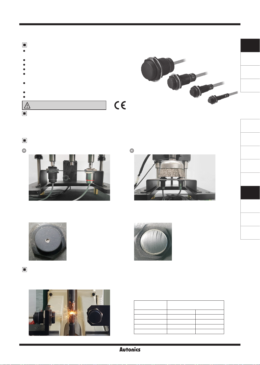
Durability Test
Highly resistant to the impact of removing welding sludge attached to the sensing face
Continuous hitting test Metallic brush test
SENSORS
CONTROLLERS
MOTION DEVICES
SOFTWARE
(A)
Photoelectric
Sensors
(B)
Fiber Optic
Sensors
(C)
LiDAR
Test conditions
Hitting object: 1.3kg of weight
Hitting speed: 48 times per 1 min
The number of hitting times: 300 thousand times
Test model: PRFA18
Test conditions
Testing object: stainless cup brush
Rotation speed: 80RPM
Testing time: 3 hours
Test model: PRFA18
<Test result> <Test result>
Electromagnetic Resistance Test
Large current from welding generates magnetic eld which can affect the proximity sensor to malfunction due to noise.
This product, however, can be used near strong noise without malfunctioning, thanks to excellent electromagnetic resistance.
This test is conducted in the environment of welding.
Test conditions
Welding current: 13,000A
Installation direction: front and side
Test model: PRFA Series
Diameter of
sensing side
Minimum sensing distance between
weld and sensor
Installation direction Front Side
8mm 60mm 70mm
12mm 30mm 60mm
18mm 10mm 50mm
30mm 120mm 120mm
※Minimum sensing distance can be different by welding
environment.
F-37
(D)
Door/Area
Sensors
(E)
Vision
Sensors
(F)
Proximity
Sensors
(G)
Pressure
Sensors
(H)
Rotary
Encoders
(I)
Connectors/
Connector Cables/
Sensor Distribution
Boxes/ Sockets
PRFA Series
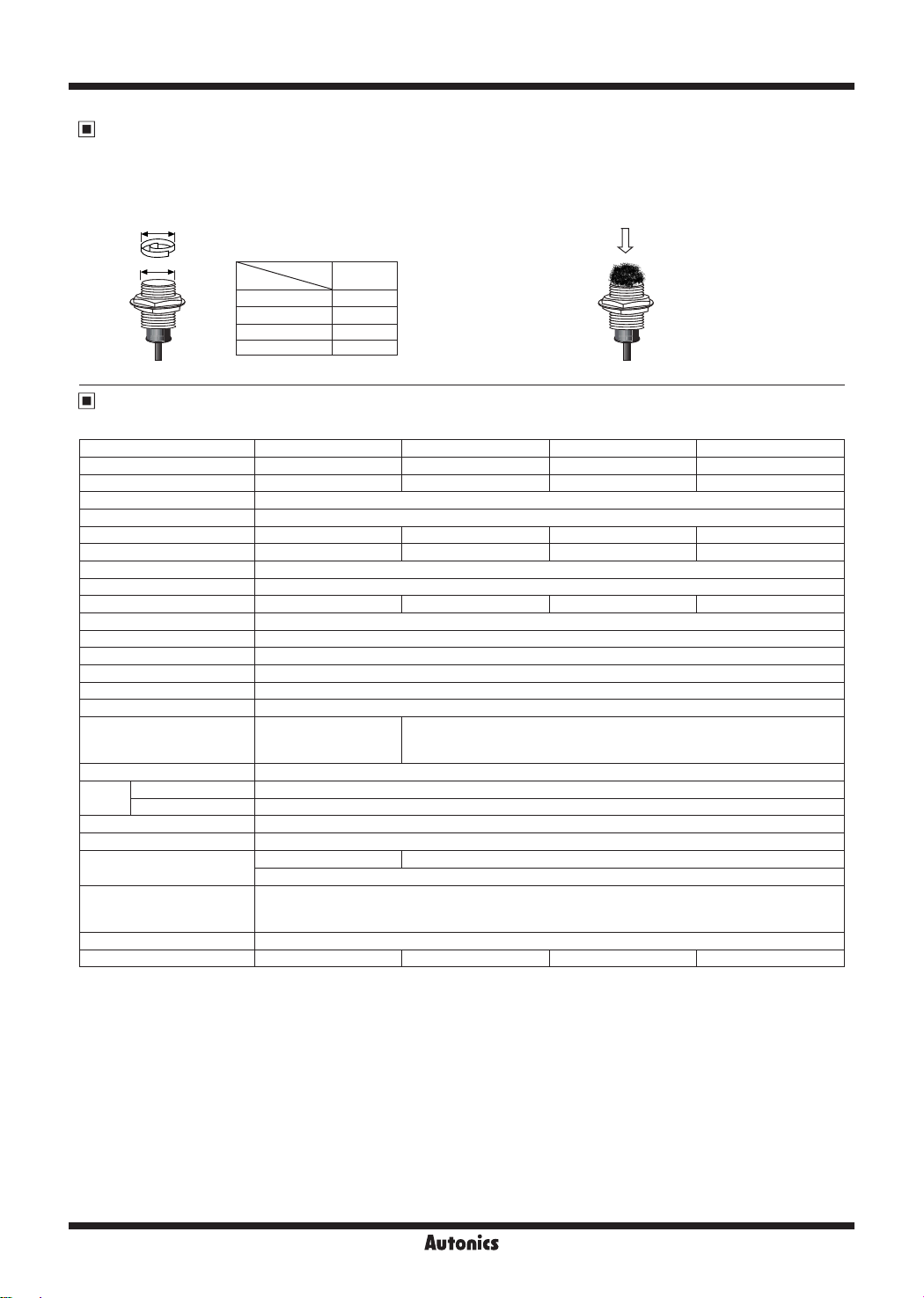
Effect of Aluminum Scraps
When aluminum scraps are attached or stacked at sensing side, the proximity sensor does not detect and sensing signal is OFF.
However, the below cases may occur to sensing signal. In this case, remove the scraps.
(1) When the size of aluminum scraps (d) is bigger than 2/3 of the
sensing side size (D)
(d)
(D)
Model
PRFAT08 6
PRFAT12 10
PRFAT18 16
PRFAT30 28
Size
D (mm)
Specifications
● DC 2-wire type
Model
Diameter of sensing side 8mm 12mm 18mm 30mm
Sensing distance
※
1
Installation Shield (ush)
Hysteresis Max. 15% of sensing distance
Standard sensing target 8×8×1mm (iron) 12×12×1mm (iron) 30×30×1mm (iron) 54×54×1mm (iron)
Setting distance 0 to 1.05mm 0 to 1.4mm 0 to 3.5mm 0 to 7mm
Power supply (operating voltage)
Leakage current Max. 0.8mA
Response frequency
※
2
Residual voltage Max. 3.5V
Affection by Temp. Max. ±20% for sensing distance at ambient temperature 20
Control output Max. 3 to 100mA
Insulation resistance Over 50MΩ (at 500VDC megger)
Dielectric strength 1,000VAC 50/60Hz for 1 min
Vibration 1.5mm amplitude at frequency 10 to 55Hz (for 1 min) in each X, Y, Z direction for 2 hours
Shock
Indicator Operation indicator: Red LED
Ambient temperature -25 to 70℃, storage: -25 to 70
Environ-
ment
Ambient humidity 35 to 95%RH, storage: 35 to 95%RH
Protection circuit Surge protection circuit, output short over current protection circuit
Protection IP67 (IEC standard)
※
3
Cable
Material
Approval
※
5
Weight
※
1: Use accessories (nut, washer) made of SUS. Or, sensing distance cannot be guaranteed.
2: The response frequency is the average value. The standard sensing target is used and the width is set as 2 times of the standard
※
sensing target, 1/2 of the sensing distance for the distance.
※
3: Do not pull the Ø4mm cable with a tensile strength of 30N or over and the Ø5mm cable with a tensile strength of 50N or over.
It may result in fire due to the broken wire. When extending wire, use AWG22 cable or over within 200m.
※
4: Option is 5m.
5: The weight includes packaging. The weight in parenthesis is for unit only.
※
※
Environment resistance is rated at no freezing or condensation.
PRFAT08-1.5DO-V PRFAT12-2DO-V PRFAT18-5DO-V PRFAT30-10DO-V
1.5mm 2mm 5mm 10mm
12-24VDCᜡ (10-30VDCᜡ)
200Hz 100Hz 80Hz 50Hz
500m/s2 (approx. 50G)
in each X, Y, Z direction
1,000m/s2 (approx. 100G) in each X, Y, Z direction for 10 times
for 10 times
℃
※
Ø4mm, 2-wire, 2m
4
Ø5mm, 2-wire, 2m
AWG22, core diameter: 0.08mm, no. of cores: 60, insulator diameter: Ø1.25mm
Case/Nut: Stainless steel 303 (SUS303, PTFE coated), Washer: Stainless steel 304 (SUS304),
Sensing side: Stainless steel 303 (SUS303 , PTFE coated, thickness is 0.8mm, in case of PRFAT08 is 0.4mm),
Oil resistant cable (gray): Oil resistant polyvinyl chloride (PVC)
ᜢ
Approx. 80g (approx. 55g) Approx. 110g (approx. 83g)
(2) When aluminum scraps are attached on the sensing side by
external pressure
External pressure
Aluminum scraps
℃
※
4
Approx. 132g (approx. 97g)
Approx. 225g (approx. 170g)
F-38

Full Metal, Cylindrical, Spatter-Resistance, Cable Type
Dimensions
Ø15
13
PRFAT18-5DO-V
Ø29
24
Control Output Diagram & Load Operating
● DC 2-wire type
Main circuit
48
28
Operation
M8×1
4
4
36
50
M18×1
indicator (red)
Operation
indicator (red)
Ø4, 2m
Ø5, 2m
Normally Open (N.O.)
Brown
Load
+V
Sensing
target
Load
Blue
0V
Opreration
Indicator
(red LED)
PRFAT12-2DO-V PRFAT08-1.5DO-V
Ø21
17
PRFAT30-10DO-V
Ø42
36
Presence
Nothing
Operation
Return
ON
OFF
(unit: mm)
SENSORS
46
33
4
5
indicator (red)
54
40
Operation
M30×1.5
indicator (red)
Operation
M12×1
Ø5, 2m
Ø5, 2m
CONTROLLERS
MOTION DEVICES
SOFTWARE
(A)
Photoelectric
Sensors
(B)
Fiber Optic
Sensors
(C)
LiDAR
(D)
Door/Area
Sensors
(E)
Vision
Sensors
(F)
Proximity
Sensors
(G)
Pressure
Sensors
(H)
Rotary
Encoders
(I)
Connectors/
Connector Cables/
Sensor Distribution
Boxes/ Sockets
Connections
● DC 2-wire type
Brown
Load
Blue
Brown
Blue
Load
※
Load can be wired to any direction.
+24VDC
0V
+24VDC
0V
F-39

PRFA Series
Sensing Distance Feature Data by Target
Material and Size
PRFAT08-1.5DO-V
1.80
1.60
1.40
1.20
1.00
0.80
0.60
Sensing distance X (mm)
0.40
0.20
0.00
4 8 10 12 15 18 20 25
※
1: Aluminum(ALS052), Copper(C1100)
PRFAT18-5DO-V
One side length of sensing target d (mm)
12.00
10.00
8.00
6.00
4.00
2.00
Sensing distance X (mm)
0.00
4 8 10 12 15 18 20 25
※
1: Aluminum(ALS052), Copper(C1100)
One side length of sensing target d (mm)
30
35 40
30
35 40
45 50
45 50
60
60
70
70
75 80
75 80
90 100
90 100
Iron (SS401)
Stainless steel 364
(SUS364)
Brass (C3601)
※
1
Iron (SS401)
Stainless steel 364
(SUS364)
Brass (C3601)
※
1
※
Detecting
Method
PRFAT12-2DO-V
2.50
2.00
1.50
1.00
Sensing distance X (mm)
0.50
0.00
4 8
10 12 15 18
1: Brass(C3601), Aluminum(ALS052), Copper(C1100)
PRFAT30-10DO-V
20 25 30 35 40
One side length of sensing target d (mm)
12.00
10.00
8.00
6.00
4.00
2.00
Sensing distance X (mm)
0.00
4 8 10 12 15 18 20 25
One side length of sensing target d (mm)
30
35 40
45
45 50
50
60
60
70
70 75 80
75 80
Sensing
distance (X)
90 100
90 100
d
target
Sensing
Iron (SS401)
Stainless steel 364
(SUS364)
※
1
Iron (SS401)
Stainless steel 364
(SUS364)
Brass (C3601)
Aluminum (ALS052)
Copper (C1100)
length
One side
Sensing Distance Feature Data by
Parallel (Left/Right) Movement
PRFAT08-1.5DO-V
1.5
1.3
1.1
0.9
0.7
Sensing area (mm)
0.5
0.3
0.1
3.0 2.0 1.0 0.0 1.0 2.0 3.0
Left ← Center → Right
Sensing area Y (mm)
PRFAT12-2DO-V
2.0
1.5
Sensing area (mm)
1.0
0.5
3.0 2.0 1.0
0.0 1.0
Left ← Center → Right
Sensing area Y (mm)
2.0 3.0
PRFAT18-5DO-V
5.0
4.0
3.0
Sensing area (mm)
2.0
1.0
6.0 4.0
2.0
0.0
Left ← Center → Right
Sensing area Y (mm)
2.0
4.0 6.0
Sensing
area (Y)
Detecting
Method
PRFAT30-10DO-V
10.0
9.0
8.0
7.0
6.0
5.0
Sensing area (mm)
4.0
3.0
2.0
1.0
15.0 10.0 5.0 0.0 5.0 10.0 15.0
Left ← Center → Right
Sensing area Y (mm)
Sensing
target
Sensing
distance (X)
F-40

Full Metal, Cylindrical, Spatter-Resistance, Cable Type
Proper Usage
Load connections
Brown
+
POWER
Blue
-
<DC 2-wire type> <DC 2-wire type>
When using DC 2-wire type proximity sensor, the load must be connected, otherwise internal components may be
damaged. The load can be connected to either wire.
In case of the load current is small
● DC 2-wire type
Brown
Load
+
Bleeder resistor(R)
Blue
Vs
-
Vs: Power supply,
[
Ioff: Return current of load,
Please make the current on proximity sensor smaller than the return current of load by connecting a bleeder resistor in
parallel.
※
W value of Bleeder resistor should be bigger for proper heat dissipation.
R ≤
Io-Ioff
Brown
Load
+
24VDC
-
Load
Blue
V
s
(kΩ)
P >
V
R
s
2
(W)
Io: Min. action current of proximity sensor,
P: Number of Bleeder resistance watt
SENSORS
CONTROLLERS
MOTION DEVICES
SOFTWARE
(A)
Photoelectric
Sensors
(B)
Fiber Optic
Sensors
]
(C)
LiDAR
(D)
Door/Area
Sensors
Mutual-interference & Influence by surrounding metals
When several proximity sensors are mounted close to one another a malfunction of the may be caused due to mutual
interference. Therefore, be sure to keep a minimum distance between the two sensors as below chart indicates.
Parallel
A
Face to Face
B
When sensors are mounted on metallic panel, it is required to protect the sensors from being affected by any metallic
object except target. Therefore, be sure to provide a minimum distance as below chart indicates.
m
Ød
ℓ
Item
ℓ
Model
PRFAT08-1.5DO-V PRFAT12-2DO-V PRFAT18-5DO-V PRFAT30-10DO-V
A 35 40 65 110
B 30 35 60 100
ℓ 0 0 0 0
Ød 8 12 18 30
m 4.5 8 20 40
n 30 40 60 100
n
ℓ
(unit: mm)
(E)
Vision
Sensors
(F)
Proximity
Sensors
(G)
Pressure
Sensors
(H)
Rotary
Encoders
(I)
Connectors/
Connector Cables/
Sensor Distribution
Boxes/ Sockets
F-41
 Loading...