

Autonics PRD Series Catalog Page
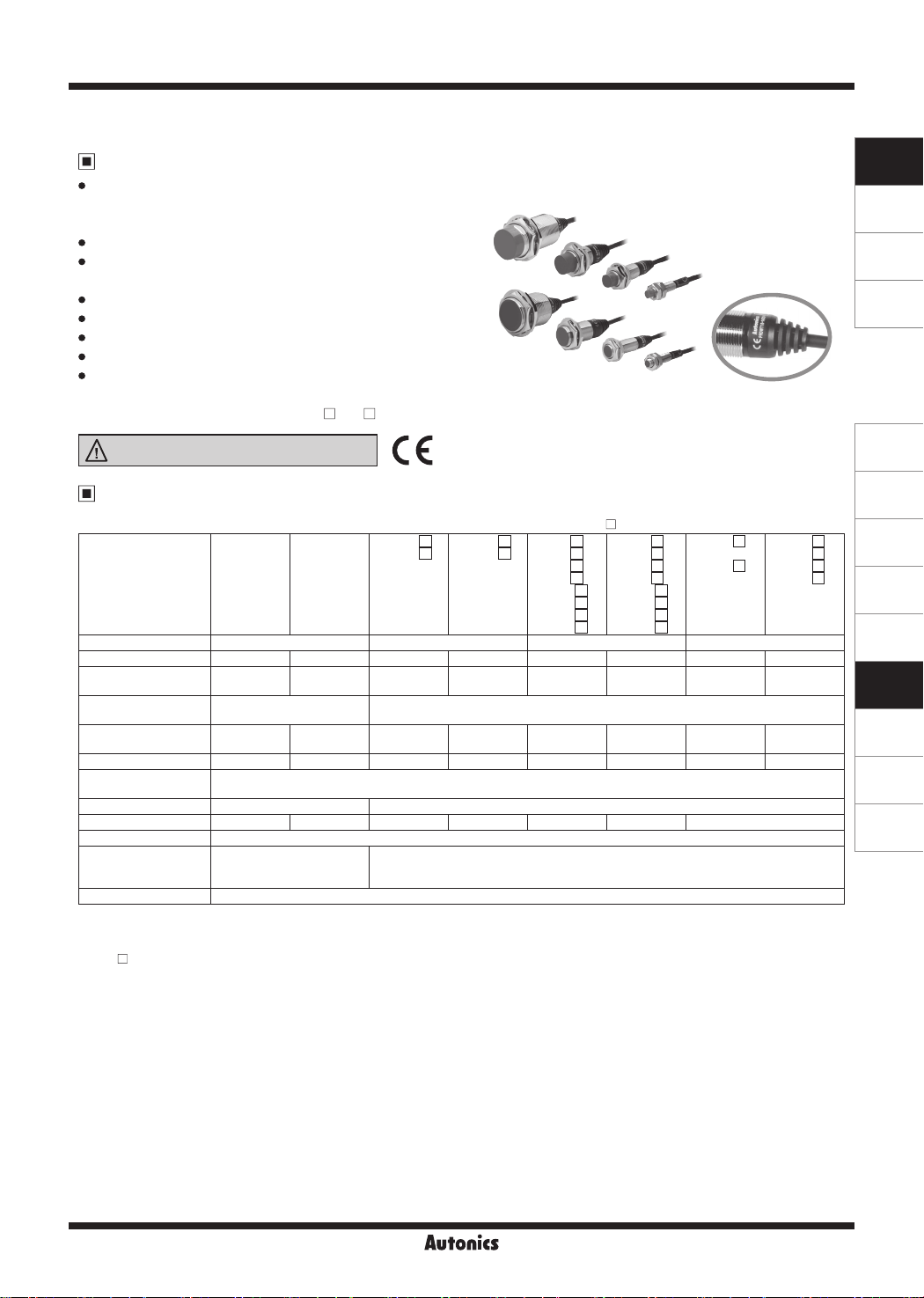
PRD Series
Cylindrical, Long Sensing Distance, Cable Type Proximity Sensor
Features
Long sensing distance
(1.5 to 2 times longer sensing distance guaranteed
compared to existing models)
Improved the noise immunity with dedicated IC
Built-in surge protection, reverse polarity protection,
output short over current protection circuit
Long life cycle and high reliability, and simple operation
Red LED operation indicator
IP67 protection structure (IEC standard)
Replaceable for micro switches and limit switches
Strain relief cables
:improvedexuralstrengthofcableconnecting
component (except for PRDT08- DO- )
Please read “Safety Considerations”
in the instruction manual before using.
Specifications
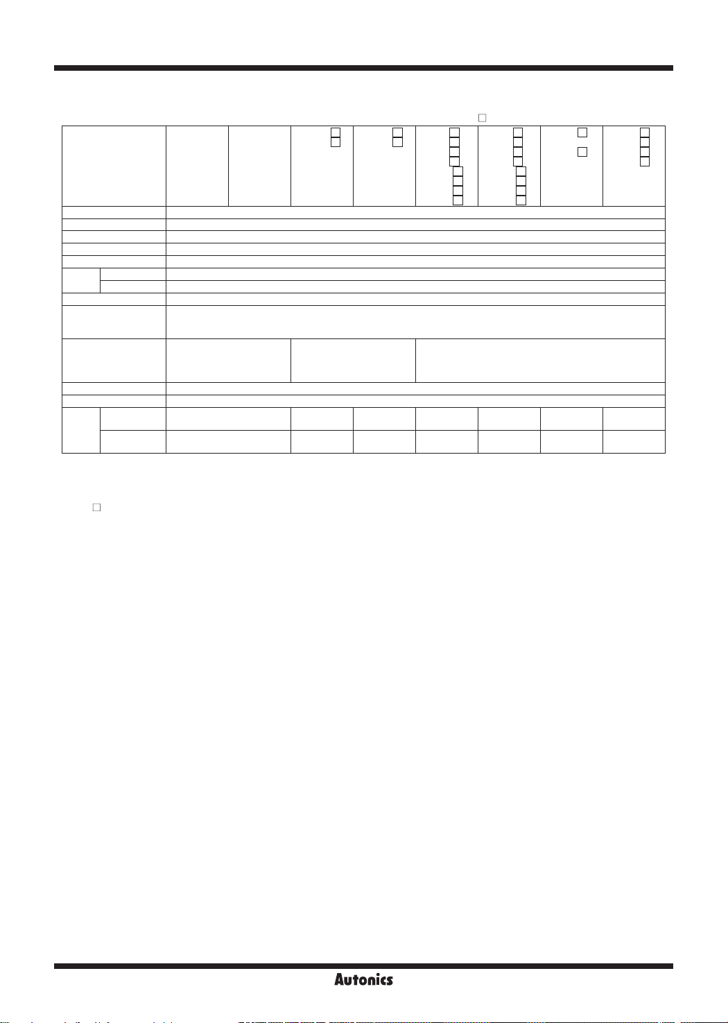
● DC 2-wire type
PRDT08-2DO
Model
Diameter of sensing side
Sensing distance 2mm 4mm 4mm 8mm 7mm 14mm 15mm 25mm
Installation Shield(ush)
Hysteresis
Standard sensing target
Setting distance 0 to 1.4mm 0 to 2.8mm 0 to 2.8mm 0 to 5.6mm 0 to 4.9mm 0 to 9.8mm 0 to 10.5mm 0 to 17.5mm
Power supply
(operating voltage)
Leakage current Max. 0.8mA Max. 0.6mA
Response frequency
Residual voltage
AectionbyTemp.
Control output 2 to 100mA
※
1: The response frequency is the average value. The standard sensing target is used and the width is set as 2 times of the standard
sensing target, 1/2 of the sensing distance for the distance.
※
2: Before using non-polarity type, check the condition of connected divice because residual voltage is 5V.
※
The ' ' of model name is for power type. 'D' is 12-24VDC, 'X' is non-polarity 12-24VDC.
※
The last 'V' of model name is for the model with oil-resistance reinforced cable.
PRDT08-2DC
PRDT08-2DO-V
PRDT08-2DC-V
8mm 12mm 18mm 30mm
Max. 15% of sensing
distance
8×8×1mm
(iron)
12-24VDCᜡ
(10-30VDCᜡ)
1
※
1kHz 800Hz 450Hz 400Hz 250Hz 200Hz 100Hz
2
※
Max. 3.5V (non-polarity type is max. 5V)
Max. ±15% for sensing
distance at ambient
temperature 20℃
PRDT08-4DO
PRDT08-4DC
PRDT08-4DO-V
PRDT08-4DC-V
Non-Shield
(non-ush)
12×12×1mm
(iron)
※
When the model name is X, it is non-polarity model.
PRDT12-4 D O
PRDT12-4 D C
PRDT12-4DO-V
PRDT12-4DC-V
PRDLT12-4DO
PRDLT12-4DC
PRDLT12-4DO-V
PRDLT12-4DC-V
Shield
(ush)
PRDT12-8 D O
PRDT12-8 D C
PRDT12-8DO-V
PRDT12-8DC-V
PRDLT12-8DO
PRDLT12-8DC
PRDLT12-8DO-V
PRDLT12-8DC-V
Non-Shield
(non-ush)
PRDT18-7 D O
PRDT18-7 D C
PRDT18-7 D O-V
PRDT18-7 D C-V
PRDLT18-7 D O
PRDLT18-7 D C
PRDLT18-7 D O-V
PRDLT18-7 D C-V
Shield
(ush)
PRDT18-14 D O
PRDT18-14 D C
PRDT18-14 D O-V
PRDT18-14 D C-V
PRDLT18-14 D O
PRDLT18-14 D C
PRDLT18-14 D O-V
PRDLT18-14 D C-V
Non-Shield
(non-ush)
PRDT30-15 D O
PRDT30-15DC
PRDT30-15 D O-V
PRDT30-15DC-V
PRDLT30-15DO
PRDLT30-15DC
PRDLT30-15DO-V
PRDLT30-15DC-V
Shield
(ush)
Max. 10% of sensing distance
12×12×1mm
(iron)
25×25×1mm
(iron)
20×20×1mm
(iron)
40×40×1mm
(iron)
45×45×1mm
(iron)
Max. ±10% for sensing distance at ambient temperature 20℃
PRDT30-25 D O
PRDT30-25 D C
PRDT30-25 D O-V
PRDT30-25 D C-V
PRDLT30-25DO
PRDLT30-25DC
PRDLT30-25DO-V
PRDLT30-25DC-V
Non-Shield
(non-ush)
75×75×1mm
(iron)
SENSORS
CONTROLLERS
MOTION DEVICES
SOFTWARE
(A)
Photoelectric
Sensors
(B)
Fiber Optic
Sensors
(C)
LiDAR
(D)
Door/Area
Sensors
(E)
Vision
Sensors
(F)
Proximity
Sensors
(G)
Pressure
Sensors
(H)
Rotary
Encoders
(I)
Connectors/
Connector Cables/
Sensor Distribution
Boxes/ Sockets
F-99
PRD Series
● DC 2-wire type
※
When the model name is X, it is non-polarity model.
PRDT18-7 D O
PRDT18-7 D C
PRDT18-7 D O-V
PRDT18-7 D C-V
PRDLT18-7 D O
PRDLT18-7 D C
PRDLT18-7 D O-V
PRDLT18-7 D C-V
Model
PRDT08-2DO
PRDT08-2DC
PRDT08-2DO-V
PRDT08-2DC-V
PRDT08-4DO
PRDT08-4DC
PRDT08-4DO-V
PRDT08-4DC-V
PRDT12-4 D O
PRDT12-4 D C
PRDT12-4DO-V
PRDT12-4DC-V
PRDLT12-4DO
PRDLT12-4DC
PRDLT12-4DO-V
PRDLT12-4DC-V
PRDT12-8 D O
PRDT12-8 D C
PRDT12-8DO-V
PRDT12-8DC-V
PRDLT12-8DO
PRDLT12-8DC
PRDLT12-8DO-V
PRDLT12-8DC-V
Insulation resistance Over50MΩ(at500VDCmegger)
Dielectric strength 1,500VAC 50/60Hz for 1 min
Vibration 1mm amplitude at frequency 10 to 55Hz (for 1 min) in each X, Y, Z direction for 2 hours
Shock 500m/s² (approx. 50G) in each X, Y, Z direction for 3 times
Indicator Operation indicator: Red LED
Ambient temp. -25 to 70℃, storage: -30 to 80
Environment
Ambient humi. 35 to 95% RH, storage: 35 to 95% RH
℃
Protection circuit Surge protection circuit, reverse polarity protection circuit, output short over current protection circuit
Material
※
Cable
Approval
3
Case/Nut: Nickel plated brass (case of PRDT08: SUS303), Washer: Nickel plated iron,
Sensing surface: Polybutylene terephthalate,
Standard cable (black): Polyvinyl chloride (PVC), oil resistant cable (gray): Oil resistant polyvinyl chloride (PVC)
Ø3.5mm, 2-wire, 2m
(AWG24, core diameter: 0.08mm,
number of cores: 40,
insulator diameter: Ø1.0mm)
Ø4mm, 2-wire, 2m
(AWG22, core diameter: 0.08mm,
Number of cores: 60,
i
nsulator diameter: Ø1.25mm)
Ø5mm, 2-wire, 2m
(AWG22, Core diameter: 0.08mm, Number of cores: 60,
Insulator diameter: Ø1.25mm)
ᜢ
Protection structure IP67 (IEC standard)
PRDT Approx. 58g(approx. 50g)
Weight
4
※
PRDLT
※
3: Do not pull the Ø3.5mm cable with a tensile strength of 25N, the Ø4mm cable with a tensile strength of 30N or over and the
-
Approx. 74g
(approx. 62g)
Approx. 94g
(approx. 82g)
Approx. 72g
(approx. 60g)
Approx. 92g
(approx. 80g)
Approx. 115g
(approx. 97g)
Approx. 145g
(approx. 127g)
Ø5mm cable with a tensile strength of 50N or over.
Itmayresultinreduetothebrokenwire.Whenextendingwire,useAWG22cableoroverwithin200m.
※
4: The weight includes packaging. The weight in parenthesis in for unit only.
※
The ' ' of model name is for power type. 'D' is 12-24VDC, 'X' is non-polarity 12-24VDC.
※
The last 'V' of model name is for the model with oil-resistance reinforced cable.
※
Environment resistance is rated at no freezing or condensation.
PRDT18-14 D O
PRDT18-14 D C
PRDT18-14 D O-V
PRDT18-14 D C-V
PRDLT18-14 D O
PRDLT18-14 D C
PRDLT18-14 D O-V
PRDLT18-14 D C-V
Approx. 110g
(approx. 92g)
Approx. 140g
(approx. 122g)
PRDT30-15 D O
PRDT30-15DC
PRDT30-15 D O-V
PRDT30-15DC-V
PRDLT30-15DO
PRDLT30-15DC
PRDLT30-15DO-V
PRDLT30-15DC-V
Approx. 175g
(approx. 138g)
Approx. 215g
(approx. 178g)
PRDT30-25 D O
PRDT30-25 D C
PRDT30-25 D O-V
PRDT30-25 D C-V
PRDLT30-25DO
PRDLT30-25DC
PRDLT30-25DO-V
PRDLT30-25DC-V
Approx. 180g
(approx. 143g)
Approx. 220g
(approx. 183g)
F-100
Cylindrical, Long Sensing Distance, Cable Type
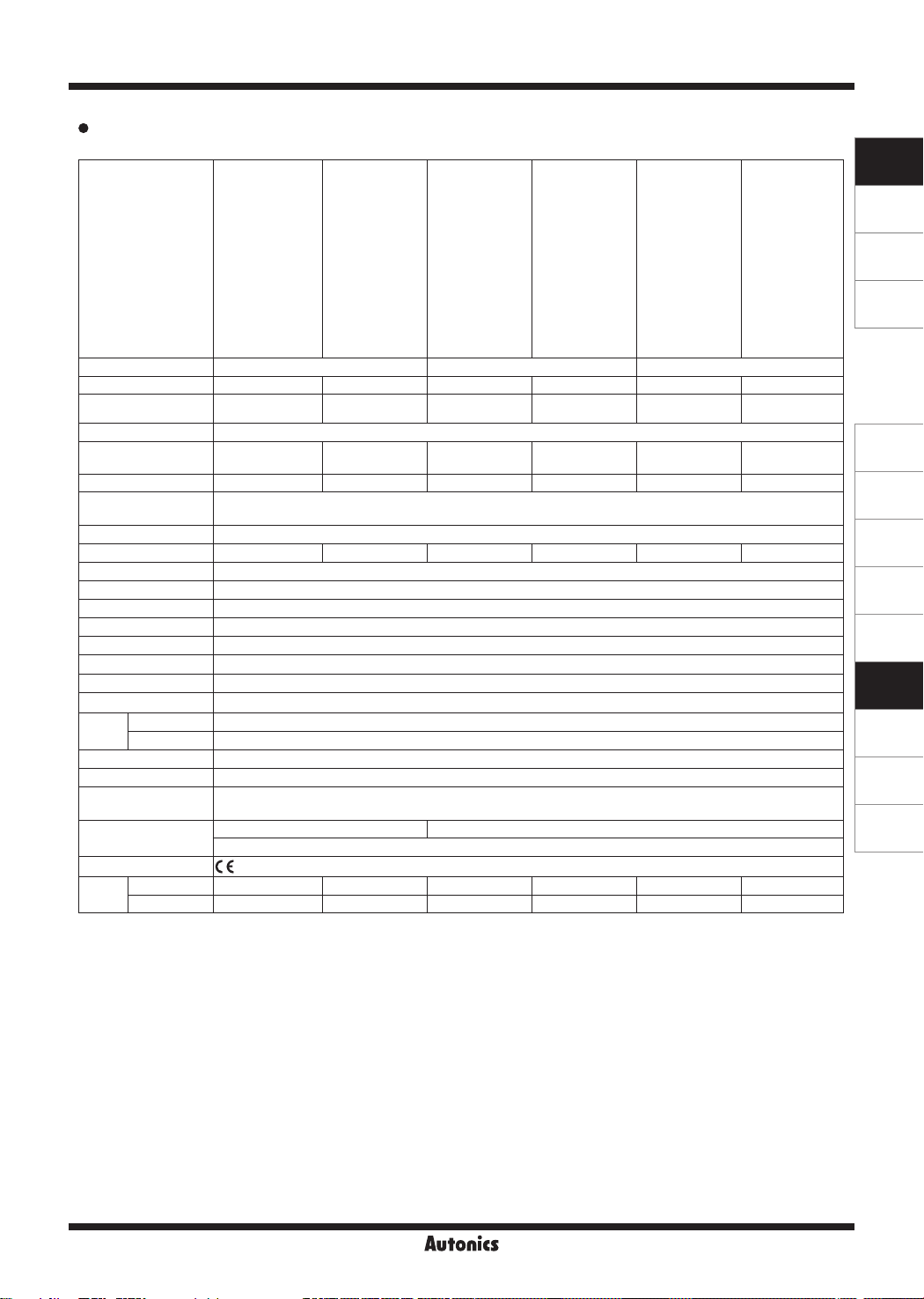
DC 3-wire type
Model
Diameter of sensing side
PRD30-15DN
PRD30-15DP
PRD30-15DN2
PRD30-15DP2
PRD30-15DN-V
PRD30-15DP-V
PRD30-15DN2-V
PRD30-15DP2-V
PRDL30-15DN
PRDL30-15DP
PRDL30-15DN2
PRDL30-15DP2
PRD12-4DN
PRD12-4DP
PRD12-4DN2
PRD12-4DP2
PRDL12-4DN
PRDL12-4DP
PRDL12-4DN2
PRDL12-4DP2
PRD12-8DN
PRD12-8DP
PRD12-8DN2
PRD12-8DP2
PRDL12-8DN
PRDL12-8DP
PRDL12-8DN2
PRDL12-8DP2
PRD18-7DN
PRD18-7DP
PRD18-7DN2
PRD18-7DP2
PRD18-7DN-V
PRD18-7DP-V
PRDL18-7DN
PRDL18-7DP
PRDL18-7DN2
PRDL18-7DP2
PRDL18-7DN-V
PRD18-14DN
PRD18-14DP
PRD18-14DN2
PRD18-14DP2
PRD18-14DN-V
PRD18-14DP-V
PRDL18-14DN
PRDL18-14DP
PRDL18-14DN2
PRDL18-14DP2
PRDL18-14DP-V
PRDL30-15DN-V
12mm 18mm 30mm
PRD30-25DN
PRD30-25DP
PRD30-25DN2
PRD30-25DP2
PRD30-25DN-V
PRD30-25DP-V
PRD30-25DN2-V
PRD30-25DP2-V
PRDL30-25DN
PRDL30-25DP
PRDL30-25DN2
PRDL30-25DP2
PRDL30-25DN-V
Sensing distance 4mm 8mm 7mm 14mm 15mm 25mm
Installation
Shield
(ush)
Non-Shield
(non-ush)
Shield
(ush)
Non-Shield
(non-ush)
Shield
(ush)
Non-Shield
(non-ush)
Hysteresis Max. 10% of sensing distance
Standard sensing
target
12×12×1mm (iron) 25×25×1mm (iron) 20×20×1mm (iron) 40×40×1mm (iron) 45×45×1mm (iron)
75×75×1mm (iron)
Setting distance 0 to 2.8mm 0 to 5.6mm 0 to 4.9mm 0 to 9.8mm 0 to 10.5mm 0 to 17.5mm
Power supply
(operating voltage)
Leakage current Max. 10mA
Response frequency
12-24VDCᜡ
(10-30VDCᜡ)
1
※
500Hz 400Hz 300Hz 200Hz 100HZ 100Hz
Residual voltage Max. 1.5V
AectionbyTemp.
Max. ±10% for sensing distance at ambient temperature 20℃
Control output 200mA
Insulation resistance Over50MΩ(at500VDCmegger)
Dielectric strength 1,500VAC 50/60Hz for 1 min
Vibration 1mm amplitude at frequency 10 to 55Hz (for 1 min) in each X, Y, Z direction for 2 hours
Shock 500m/s² (approx. 50G) in each X, Y, Z direction for 3 times
Indicator Operation indicator: Red LED
Ambient temp. -25 to 70℃, storage: -30 to 80
Environment
Ambient humi. 35 to 95%RH, storage: 35 to 95%RH
℃
Protection circuit Surge protection circuit, Reverse polarity protection circuit, output short over current protection circuit
Protection structure IP67 (IEC standard)
Material
Cable
2
※
Case/Nut: Nickel plated Brass, Washer: Nickel plated Iron, Sensing surface: Polybutylene terephthalate,
Standard cable (black): Polyvinyl chloride (PVC), Oil resistant cable (gray): Oil resistant Polyvinyl chloride (PVC)
Ø4mm, 3-wire, 2m Ø5mm, 3-wire, 2m
AWG22, Core diameter: 0.08mm, Number of cores: 60, Insulator diameter: Ø1.25mm
Approval
PRD Approx. 74g Approx. 72g Approx. 115g Approx. 110g Approx. 175g Approx. 180g
Unit
weight
PRDL
※
1: The response frequency is the average value. The standard sensing target is used and the width is set as 2 times of the standard
sensing target, 1/2 of the sensing distance for the distance.
※
2: Do not pull the Ø4mm cable with a tensile strength of 30N or over and the Ø5mm cable with a tensile strength of 50N or over.
Itmayresultinreduetothebrokenwire.Whenextendingwire,useAWG22cableoroverwithin200m.
※
The last 'V' of model name is for the model with oil-resistance reinforced cable.
※
Environment resistance is rated at no freezing or condensation.
Approx. 94g Approx. 92g Approx. 145g Approx. 140g Approx. 215g Approx. 220g
SENSORS
CONTROLLERS
MOTION DEVICES
SOFTWARE
(A)
Photoelectric
Sensors
(B)
Fiber Optic
Sensors
(C)
LiDAR
(D)
Door/Area
Sensors
(E)
Vision
Sensors
(F)
Proximity
Sensors
(G)
Pressure
Sensors
(H)
Rotary
Encoders
(I)
Connectors/
Connector Cables/
Sensor Distribution
Boxes/ Sockets
F-101
 Loading...